EP4015440B1 - Attachment device for a telehandler - Google Patents
Attachment device for a telehandler Download PDFInfo
- Publication number
- EP4015440B1 EP4015440B1 EP21212741.9A EP21212741A EP4015440B1 EP 4015440 B1 EP4015440 B1 EP 4015440B1 EP 21212741 A EP21212741 A EP 21212741A EP 4015440 B1 EP4015440 B1 EP 4015440B1
- Authority
- EP
- European Patent Office
- Prior art keywords
- crosspieces
- telehandler
- oblique
- attachment device
- inner sides
- Prior art date
- Legal status (The legal status is an assumption and is not a legal conclusion. Google has not performed a legal analysis and makes no representation as to the accuracy of the status listed.)
- Active
Links
Images


Classifications
-
- B—PERFORMING OPERATIONS; TRANSPORTING
- B66—HOISTING; LIFTING; HAULING
- B66F—HOISTING, LIFTING, HAULING OR PUSHING, NOT OTHERWISE PROVIDED FOR, e.g. DEVICES WHICH APPLY A LIFTING OR PUSHING FORCE DIRECTLY TO THE SURFACE OF A LOAD
- B66F9/00—Devices for lifting or lowering bulky or heavy goods for loading or unloading purposes
- B66F9/06—Devices for lifting or lowering bulky or heavy goods for loading or unloading purposes movable, with their loads, on wheels or the like, e.g. fork-lift trucks
- B66F9/075—Constructional features or details
- B66F9/07504—Accessories, e.g. for towing, charging, locking
-
- B—PERFORMING OPERATIONS; TRANSPORTING
- B66—HOISTING; LIFTING; HAULING
- B66F—HOISTING, LIFTING, HAULING OR PUSHING, NOT OTHERWISE PROVIDED FOR, e.g. DEVICES WHICH APPLY A LIFTING OR PUSHING FORCE DIRECTLY TO THE SURFACE OF A LOAD
- B66F9/00—Devices for lifting or lowering bulky or heavy goods for loading or unloading purposes
- B66F9/06—Devices for lifting or lowering bulky or heavy goods for loading or unloading purposes movable, with their loads, on wheels or the like, e.g. fork-lift trucks
- B66F9/065—Devices for lifting or lowering bulky or heavy goods for loading or unloading purposes movable, with their loads, on wheels or the like, e.g. fork-lift trucks non-masted
- B66F9/0655—Devices for lifting or lowering bulky or heavy goods for loading or unloading purposes movable, with their loads, on wheels or the like, e.g. fork-lift trucks non-masted with a telescopic boom
-
- B—PERFORMING OPERATIONS; TRANSPORTING
- B66—HOISTING; LIFTING; HAULING
- B66C—CRANES; LOAD-ENGAGING ELEMENTS OR DEVICES FOR CRANES, CAPSTANS, WINCHES, OR TACKLES
- B66C23/00—Cranes comprising essentially a beam, boom, or triangular structure acting as a cantilever and mounted for translatory of swinging movements in vertical or horizontal planes or a combination of such movements, e.g. jib-cranes, derricks, tower cranes
- B66C23/62—Constructional features or details
- B66C23/64—Jibs
- B66C23/68—Jibs foldable or otherwise adjustable in configuration
-
- B—PERFORMING OPERATIONS; TRANSPORTING
- B66—HOISTING; LIFTING; HAULING
- B66F—HOISTING, LIFTING, HAULING OR PUSHING, NOT OTHERWISE PROVIDED FOR, e.g. DEVICES WHICH APPLY A LIFTING OR PUSHING FORCE DIRECTLY TO THE SURFACE OF A LOAD
- B66F9/00—Devices for lifting or lowering bulky or heavy goods for loading or unloading purposes
- B66F9/06—Devices for lifting or lowering bulky or heavy goods for loading or unloading purposes movable, with their loads, on wheels or the like, e.g. fork-lift trucks
- B66F9/075—Constructional features or details
- B66F9/12—Platforms; Forks; Other load supporting or gripping members
- B66F9/16—Platforms; Forks; Other load supporting or gripping members inclinable relative to mast
Definitions
- This invention relates to an attachment device with increased operational visibility, designed for use on telescopic handlers or "telehandlers”.
- These accessories may be attached in a removable fashion to an attachment device with which the operating arm is provided.
- the attachment device commonly known as “quick coupling”
- the attachment device can be mounted in a removable fashion or directly at the distal end of the operating arm.
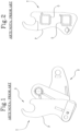
- a prior art quick coupling A includes two main components: a central and rear attachment structure S, which is the part mounted on the arm and a front frame T, which is the part to which the accessory is attached.
- the front frame T comprises a frame structure formed by two lateral plates P and two tubular crosspieces O with a quadrangular or circular cross-section, fixed above and below the central and rear structure S, which join the plates P to each other.
- the plates P form upper hooks and are equipped with lower holes which are used for the removable attachment of the accessory.
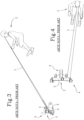
- the prior art quick couplings A constitute an obstacle for the vision of the operator which is limited to the inner free squares defined by the two crosspieces O, the central structure and the side walls P (see Figures 3 and 4 ).
- the view V of the operator U is usually facing the left-hand free box.
- EP 1 577 256 A1 discloses an attachment device according to the preamble of claim 1.
- the technical purpose which forms the basis of the invention is to provide a quick coupling for telehandlers which satisfies the above-mentioned need.
- the specified technical purpose is achieved by the attachment device for telehandlers made according to the appended claims.
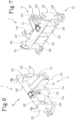
- the numeral 1 denotes in its entirety an attachment device, or “quick coupling", for telehandlers 100, made according to the invention.
- the device 1 proposed is designed to be connected in a removable fashion to an operating arm 101 of the telehandler 100 and comprises a front frame 12 which is designed for removably attaching an accessory 102 for engaging the load, such as a fork, a side shift carriage, a winch, a loading platform or others, to which reference is made in the introduction. Moreover, the device 1 comprises a central and rear attachment structure 11, which is the part which is mounted on the arm 101.
- the central structure 11 may include two opposite flanges 111, 112 which extend to the rear, each of which is equipped with a through hole 113, 114 for inserting a pin for attachment to the distal end of the operating arm 101.
- two pairs of flanges 111, 112, preferably positioned on planes parallel to each other, can be provided, equipped with respective through holes 113, 114, the first pair being designed to connect, as a possibility of rotation, to the above-mentioned end of the arm 101 and the second pair being provided for the attachment of an end of the hydraulic tilting cylinder (not illustrated), the other end of which is connected to the arm 101.
- a pair of flanges 112, preferably external, comprises two holes 114 positioned at the top for the attachment to the arm 103 and the other pair of flanges 111, preferably internal, comprises two through holes 113 positioned centrally, for the purpose of the attachment to the end of the arm of the tilting cylinder.
- Each flange 111, 112 of one pair may be joined to a respective flange of the other pair by lateral walls and/or front reinforcement walls 115, to form box-shaped structures.
- this includes two opposite lateral side elements 121, which act in practice as uprights, which may consist of lateral plates 121 and which are joined together by two opposite crosspieces 122 of which one upper and one lower, to define a frame-like configuration (see Figures 6 - 10 ).
- the two crosspieces 122 are fixed above and below one or more front portions of the above-mentioned central structure 11, so that the latter is rigidly joined to the frame 12.
- the central structure 11 is located in a median position between the two lateral side elements 121 and, in the example illustrated, its front portion closed in the form of a "sandwich" by the crosspieces 122 is defined by the above-mentioned box-shaped structures, which include the two front reinforcements 115.
- Each of the lateral side elements 121 forms a hook-shaped seat 123 and a lower through hole 124 is made in each of them, to allow the removable attachment of the accessory 102; more precisely, a bar of the accessory 102 is received by the two hook-shaped seats 123, parallel and facing each other, whilst a pin is inserted between the two lower holes 124 aligned with the lateral side elements 121 and respective holes or slots of the accessory 102, to allow the removable attachment to the device 1.
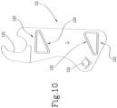
- the two crosspieces 122 are each equipped with an inner side 120 which is oblique relative to a horizontal plane; preferably the oblique sides 120 of the crosspieces 122 are parallel to each other.
- inner side 120 is used here to mean a side of the profile of the respective crosspiece 122 which faces towards the inside of the attachment device 1; in general, a fast coupling 1 can also be provided wherein at least one of the two crosspieces 122 is provided with the oblique inner side 129. It should be noted how these oblique inner sides 120 form with the inner sides of the lateral side elements 112 two free passages L, that is to say, spaces circumscribed on the perimeter of the lateral side elements 121 and the crosspieces 122, which will be described in more detail below (see Figures 8 , 11 , 12 and 14 ).
- the oblique inner sides 120 of the two crosspieces 122 are inclined downwards in a front direction; the front direction is defined by the fact that the attachment device 1 mounts the accessory 102 at the front whilst at the rear it is connected to the arm 101.
- the inner sides 120 of the crosspieces 122 are oblique to a horizontal plane, when the attachment device 1 is used on a telehandler 100 which is on horizontal ground; on the other hand, the horizontal plane in question is in reality a plane parallel to the ground or defined by the points for resting on the ground of the telehandler 100, whether it rests on the wheels or on the stabilizers; another way to express the same concept is that the inner sides 120 of the crosspieces 122 are oblique relative to a direction incident with and parallel to the longitudinal axis of the machine or the turret of the telehandler 100 (depending on whether it is fixed or rotary), to which the device 1 according to the invention is connected.
- the crosspieces 122 are preferably parallel, in the direction of their length and have the oblique inner sides 120 facing each other. According to the invention, both the crosspieces (122) have a triangular cross-section.
- the crosspieces 122 are tubular elements with a triangular cross-section which are identical but oriented in such a way as to be rotated by 180 degrees with respect to each other.
- the oblique inner sides 120 are defined by crosspieces 122 shaped in a different manner.
- the above-mentioned oblique side corresponds to an oblique wall of the respective crosspiece 122.
- each crosspiece 122 has the shape of a right-angled triangle, with the hypotenuse which constitutes the oblique inner side.
- this circumstance occurs in a lowered position of use of the attachment device 1, close to the ground, where the accessory 102 carried by it is in a position for preparing the operation for gripping the load (as in Figure 5 ).
- the direction of the vision W of the operator U, seated in the driving position, which passes through the free passages L defined between the lateral side elements 121 and the crosspieces 122, is not obstructed or is in any case obstructed less by the overall dimensions of the crosspieces 122, compared with what occurs when a prior art fast coupling A is used.
- the prior art quick couplings A have crosspieces 122 with a square or circular cross-section with inner protruding walls, which form corners or arcs of a circle, which constitute obstacles which limit the vision W of the operator. Thanks to the configuration with oblique inner sides 120, on the other hand, the invention eliminates these corners, to allow the operator U to have a much greater visibility W, thereby overcoming the drawbacks described in the introduction.
- the width of the free passage L defined in the quick coupling 1 according to the invention passing through which the operator's view W passes may be greater than the width of the opposite passage L, which is not affected by the view W.
- the distance between the left lateral side element 121 and the left box-shaped structure 114 is greater than that between the corresponding components on the right, to allow a view W which is even greater for the operator U.
Landscapes
- Engineering & Computer Science (AREA)
- Transportation (AREA)
- Structural Engineering (AREA)
- Mechanical Engineering (AREA)
- Civil Engineering (AREA)
- Life Sciences & Earth Sciences (AREA)
- Geology (AREA)
- Table Equipment (AREA)
- Mutual Connection Of Rods And Tubes (AREA)
- Forklifts And Lifting Vehicles (AREA)
- Handcart (AREA)
- Manipulator (AREA)
Priority Applications (4)
| Application Number | Priority Date | Filing Date | Title |
|---|---|---|---|
| HRP20250353TT HRP20250353T1 (hr) | 2020-12-21 | 2021-12-07 | Uređaj za pričvršćivanje za teleskopski utovarivač |
| RS20250287A RS66665B1 (sr) | 2020-12-21 | 2021-12-07 | Uređaj za pričvršćivanje za telehendler |
| SM20250139T SMT202500139T1 (it) | 2020-12-21 | 2021-12-07 | Dispositivo di attacco per telehandler |
| SI202130287T SI4015440T1 (sl) | 2020-12-21 | 2021-12-07 | Pritrdilna naprava za teleskopski viličar |
Applications Claiming Priority (1)
| Application Number | Priority Date | Filing Date | Title |
|---|---|---|---|
| IT202000031643 | 2020-12-21 |
Publications (2)
| Publication Number | Publication Date |
|---|---|
| EP4015440A1 EP4015440A1 (en) | 2022-06-22 |
| EP4015440B1 true EP4015440B1 (en) | 2025-01-22 |
Family
ID=74858655
Family Applications (1)
| Application Number | Title | Priority Date | Filing Date |
|---|---|---|---|
| EP21212741.9A Active EP4015440B1 (en) | 2020-12-21 | 2021-12-07 | Attachment device for a telehandler |
Country Status (16)
| Country | Link |
|---|---|
| US (1) | US12448260B2 (pl) |
| EP (1) | EP4015440B1 (pl) |
| CN (1) | CN114644306A (pl) |
| AU (1) | AU2021286402A1 (pl) |
| DK (1) | DK4015440T3 (pl) |
| ES (1) | ES3017240T3 (pl) |
| FI (1) | FI4015440T3 (pl) |
| HR (1) | HRP20250353T1 (pl) |
| HU (1) | HUE070678T2 (pl) |
| LT (1) | LT4015440T (pl) |
| PL (1) | PL4015440T3 (pl) |
| PT (1) | PT4015440T (pl) |
| RS (1) | RS66665B1 (pl) |
| SI (1) | SI4015440T1 (pl) |
| SM (1) | SMT202500139T1 (pl) |
| ZA (1) | ZA202110394B (pl) |
Family Cites Families (11)
| Publication number | Priority date | Publication date | Assignee | Title |
|---|---|---|---|---|
| JPS55151796U (pl) * | 1979-04-16 | 1980-11-01 | ||
| JPS55151796A (en) | 1979-05-16 | 1980-11-26 | Toshiba Corp | Circuit for preventing destruction of x-ray tube |
| US4545720A (en) * | 1984-05-17 | 1985-10-08 | J. I. Case Company | Quick coupler assembly |
| JP2730462B2 (ja) * | 1993-12-20 | 1998-03-25 | 株式会社豊田自動織機製作所 | フォークリフトの荷役装置 |
| US6364561B1 (en) * | 1999-05-28 | 2002-04-02 | David Scribner Droegemueller | Connector system for earth working machines |
| JP2004203553A (ja) * | 2002-12-25 | 2004-07-22 | Hitachi Constr Mach Co Ltd | 自走式作業機械 |
| JP2014025313A (ja) * | 2012-07-30 | 2014-02-06 | Kubota Corp | フロントローダ |
| EP2951121A1 (en) * | 2013-02-04 | 2015-12-09 | Crown Equipment Corporation | Reach assembly with offset pivot points for a materials handling vehicle |
| US9284712B2 (en) * | 2014-05-30 | 2016-03-15 | Cnh Industrial America Llc | Universal quick coupler for backhoe |
| US9783962B1 (en) * | 2016-09-01 | 2017-10-10 | Yanmar Co., Ltd. | Front loader |
| CN206858073U (zh) * | 2017-05-11 | 2018-01-09 | 嘉善惠丰机械有限公司 | 一种液压手动叉车 |
-
2021
- 2021-12-07 EP EP21212741.9A patent/EP4015440B1/en active Active
- 2021-12-07 FI FIEP21212741.9T patent/FI4015440T3/fi active
- 2021-12-07 SM SM20250139T patent/SMT202500139T1/it unknown
- 2021-12-07 PL PL21212741.9T patent/PL4015440T3/pl unknown
- 2021-12-07 PT PT212127419T patent/PT4015440T/pt unknown
- 2021-12-07 RS RS20250287A patent/RS66665B1/sr unknown
- 2021-12-07 SI SI202130287T patent/SI4015440T1/sl unknown
- 2021-12-07 ES ES21212741T patent/ES3017240T3/es active Active
- 2021-12-07 LT LTEP21212741.9T patent/LT4015440T/lt unknown
- 2021-12-07 HU HUE21212741A patent/HUE070678T2/hu unknown
- 2021-12-07 HR HRP20250353TT patent/HRP20250353T1/hr unknown
- 2021-12-07 DK DK21212741.9T patent/DK4015440T3/da active
- 2021-12-09 US US17/546,856 patent/US12448260B2/en active Active
- 2021-12-14 ZA ZA2021/10394A patent/ZA202110394B/en unknown
- 2021-12-17 AU AU2021286402A patent/AU2021286402A1/en active Pending
- 2021-12-20 CN CN202111566044.7A patent/CN114644306A/zh active Pending
Also Published As
| Publication number | Publication date |
|---|---|
| CN114644306A (zh) | 2022-06-21 |
| FI4015440T3 (fi) | 2025-04-04 |
| HUE070678T2 (hu) | 2025-06-28 |
| US12448260B2 (en) | 2025-10-21 |
| US20220194764A1 (en) | 2022-06-23 |
| ES3017240T3 (en) | 2025-05-12 |
| SI4015440T1 (sl) | 2025-05-30 |
| LT4015440T (lt) | 2025-04-10 |
| RS66665B1 (sr) | 2025-05-30 |
| PT4015440T (pt) | 2025-03-28 |
| ZA202110394B (en) | 2022-09-28 |
| AU2021286402A1 (en) | 2022-07-07 |
| SMT202500139T1 (it) | 2025-05-12 |
| DK4015440T3 (da) | 2025-03-24 |
| HRP20250353T1 (hr) | 2025-05-09 |
| PL4015440T3 (pl) | 2025-05-12 |
| EP4015440A1 (en) | 2022-06-22 |
Similar Documents
| Publication | Publication Date | Title |
|---|---|---|
| US4395189A (en) | Dual mast lift truck for unbalanced loads and the like | |
| CA1148122A (en) | Multi-purpose utility vehicle | |
| EP0524490B1 (de) | Baggerlader | |
| US6048161A (en) | Vehicle having a lifting boom, which can be used as an agricultural machine | |
| EP4015440B1 (en) | Attachment device for a telehandler | |
| EP3683184B1 (en) | Apparatus for self-propelled operating machine | |
| WO1984000729A1 (en) | Chassis assembly for mobile machine | |
| AU2020312719A1 (en) | An excavator having a lifting device for lifting a pallet | |
| JPS597634B2 (ja) | クレ−ン車 | |
| GB1591061A (en) | Lift-mast assembly | |
| EP3988497B1 (en) | Improved fork-carrier | |
| JP3271036B2 (ja) | クレーン車の転倒防止装置 | |
| EP1052214B1 (en) | A vehicle which can be used as a hoister and as an agricultural tractor | |
| KR101942213B1 (ko) | 신축 붐의 장착 구조 | |
| WO2008018840A1 (en) | Lifting and manipulating device for tractors | |
| AU742698B2 (en) | Improvements in fork lifts | |
| JP4459773B2 (ja) | 作業機のアタッチメント装着機構 | |
| GB2616301A (en) | A carriage assembly | |
| JPH0322362Y2 (pl) | ||
| JPH0720190Y2 (ja) | 作業用車両の作業反力支持装置 | |
| JP2561847Y2 (ja) | フォークリフトアタッチメント | |
| KR20210068941A (ko) | 포크리프트를 장착하는 굴착기 | |
| GB2197847A (en) | Agricultural material handling assembly | |
| JPH04112897U (ja) | フオークリフトの作業機取付装置 |
Legal Events
| Date | Code | Title | Description |
|---|---|---|---|
| REG | Reference to a national code |
Ref country code: HR Ref legal event code: TUEP Ref document number: P20250353T Country of ref document: HR |
|
| PUAI | Public reference made under article 153(3) epc to a published international application that has entered the european phase |
Free format text: ORIGINAL CODE: 0009012 |
|
| STAA | Information on the status of an ep patent application or granted ep patent |
Free format text: STATUS: THE APPLICATION HAS BEEN PUBLISHED |
|
| AK | Designated contracting states |
Kind code of ref document: A1 Designated state(s): AL AT BE BG CH CY CZ DE DK EE ES FI FR GB GR HR HU IE IS IT LI LT LU LV MC MK MT NL NO PL PT RO RS SE SI SK SM TR |
|
| STAA | Information on the status of an ep patent application or granted ep patent |
Free format text: STATUS: REQUEST FOR EXAMINATION WAS MADE |
|
| 17P | Request for examination filed |
Effective date: 20221214 |
|
| RBV | Designated contracting states (corrected) |
Designated state(s): AL AT BE BG CH CY CZ DE DK EE ES FI FR GB GR HR HU IE IS IT LI LT LU LV MC MK MT NL NO PL PT RO RS SE SI SK SM TR |
|
| P01 | Opt-out of the competence of the unified patent court (upc) registered |
Effective date: 20230614 |
|
| GRAP | Despatch of communication of intention to grant a patent |
Free format text: ORIGINAL CODE: EPIDOSNIGR1 |
|
| STAA | Information on the status of an ep patent application or granted ep patent |
Free format text: STATUS: GRANT OF PATENT IS INTENDED |
|
| INTG | Intention to grant announced |
Effective date: 20240710 |
|
| GRAS | Grant fee paid |
Free format text: ORIGINAL CODE: EPIDOSNIGR3 |
|
| GRAA | (expected) grant |
Free format text: ORIGINAL CODE: 0009210 |
|
| STAA | Information on the status of an ep patent application or granted ep patent |
Free format text: STATUS: THE PATENT HAS BEEN GRANTED |
|
| AK | Designated contracting states |
Kind code of ref document: B1 Designated state(s): AL AT BE BG CH CY CZ DE DK EE ES FI FR GB GR HR HU IE IS IT LI LT LU LV MC MK MT NL NO PL PT RO RS SE SI SK SM TR |
|
| REG | Reference to a national code |
Ref country code: GB Ref legal event code: FG4D |
|
| REG | Reference to a national code |
Ref country code: CH Ref legal event code: EP |
|
| REG | Reference to a national code |
Ref country code: IE Ref legal event code: FG4D |
|
| REG | Reference to a national code |
Ref country code: DE Ref legal event code: R096 Ref document number: 602021025114 Country of ref document: DE |
|
| REG | Reference to a national code |
Ref country code: DK Ref legal event code: T3 Effective date: 20250318 |
|
| REG | Reference to a national code |
Ref country code: PT Ref legal event code: SC4A Ref document number: 4015440 Country of ref document: PT Date of ref document: 20250328 Kind code of ref document: T Free format text: AVAILABILITY OF NATIONAL TRANSLATION Effective date: 20250324 |
|
| REG | Reference to a national code |
Ref country code: NL Ref legal event code: FP |
|
| REG | Reference to a national code |
Ref country code: FI Ref legal event code: FGE |
|
| REG | Reference to a national code |
Ref country code: SE Ref legal event code: TRGR |
|
| REG | Reference to a national code |
Ref country code: HR Ref legal event code: T1PR Ref document number: P20250353 Country of ref document: HR |
|
| REG | Reference to a national code |
Ref country code: ES Ref legal event code: FG2A Ref document number: 3017240 Country of ref document: ES Kind code of ref document: T3 Effective date: 20250512 |
|
| REG | Reference to a national code |
Ref country code: SK Ref legal event code: T3 Ref document number: E 46203 Country of ref document: SK |
|
| REG | Reference to a national code |
Ref country code: GR Ref legal event code: EP Ref document number: 20250400686 Country of ref document: GR Effective date: 20250514 |
|
| REG | Reference to a national code |
Ref country code: HU Ref legal event code: AG4A Ref document number: E070678 Country of ref document: HU |
|
| REG | Reference to a national code |
Ref country code: EE Ref legal event code: FG4A Ref document number: E025031 Country of ref document: EE Effective date: 20250324 |
|
| REG | Reference to a national code |
Ref country code: DE Ref legal event code: R097 Ref document number: 602021025114 Country of ref document: DE |
|
| PLBE | No opposition filed within time limit |
Free format text: ORIGINAL CODE: 0009261 |
|
| STAA | Information on the status of an ep patent application or granted ep patent |
Free format text: STATUS: NO OPPOSITION FILED WITHIN TIME LIMIT |
|
| REG | Reference to a national code |
Ref country code: CH Ref legal event code: L10 Free format text: ST27 STATUS EVENT CODE: U-0-0-L10-L00 (AS PROVIDED BY THE NATIONAL OFFICE) Effective date: 20251203 |
|
| PGFP | Annual fee paid to national office [announced via postgrant information from national office to epo] |
Ref country code: PT Payment date: 20251121 Year of fee payment: 5 |
|
| REG | Reference to a national code |
Ref country code: HR Ref legal event code: ODRP Ref document number: P20250353 Country of ref document: HR Payment date: 20251124 Year of fee payment: 5 |
|
| 26N | No opposition filed |
Effective date: 20251023 |
|
| REG | Reference to a national code |
Ref country code: CH Ref legal event code: U11 Free format text: ST27 STATUS EVENT CODE: U-0-0-U10-U11 (AS PROVIDED BY THE NATIONAL OFFICE) Effective date: 20260101 |
|
| PGFP | Annual fee paid to national office [announced via postgrant information from national office to epo] |
Ref country code: IS Payment date: 20251229 Year of fee payment: 5 |
|
| PGFP | Annual fee paid to national office [announced via postgrant information from national office to epo] |
Ref country code: LT Payment date: 20251124 Year of fee payment: 5 Ref country code: GB Payment date: 20251223 Year of fee payment: 5 |
|
| PGFP | Annual fee paid to national office [announced via postgrant information from national office to epo] |
Ref country code: NO Payment date: 20251218 Year of fee payment: 5 Ref country code: MC Payment date: 20251219 Year of fee payment: 5 |
|
| PGFP | Annual fee paid to national office [announced via postgrant information from national office to epo] |
Ref country code: SM Payment date: 20251201 Year of fee payment: 5 Ref country code: MK Payment date: 20251125 Year of fee payment: 5 Ref country code: AT Payment date: 20260113 Year of fee payment: 5 |
|
| PGFP | Annual fee paid to national office [announced via postgrant information from national office to epo] |
Ref country code: IT Payment date: 20251222 Year of fee payment: 5 Ref country code: FI Payment date: 20251222 Year of fee payment: 5 Ref country code: DK Payment date: 20251222 Year of fee payment: 5 |
|
| PGFP | Annual fee paid to national office [announced via postgrant information from national office to epo] |
Ref country code: LU Payment date: 20251222 Year of fee payment: 5 Ref country code: HR Payment date: 20251124 Year of fee payment: 5 Ref country code: HU Payment date: 20251203 Year of fee payment: 5 Ref country code: NL Payment date: 20251222 Year of fee payment: 5 Ref country code: FR Payment date: 20251223 Year of fee payment: 5 |
|
| PGFP | Annual fee paid to national office [announced via postgrant information from national office to epo] |
Ref country code: AL Payment date: 20251230 Year of fee payment: 5 Ref country code: GR Payment date: 20251218 Year of fee payment: 5 Ref country code: TR Payment date: 20251121 Year of fee payment: 5 |
|
| PGFP | Annual fee paid to national office [announced via postgrant information from national office to epo] |
Ref country code: SE Payment date: 20251222 Year of fee payment: 5 |
|
| PGFP | Annual fee paid to national office [announced via postgrant information from national office to epo] |
Ref country code: IE Payment date: 20251218 Year of fee payment: 5 Ref country code: CY Payment date: 20251127 Year of fee payment: 5 Ref country code: CZ Payment date: 20251128 Year of fee payment: 5 |
|
| PGFP | Annual fee paid to national office [announced via postgrant information from national office to epo] |
Ref country code: MT Payment date: 20251224 Year of fee payment: 5 Ref country code: LV Payment date: 20251219 Year of fee payment: 5 |
|
| PGFP | Annual fee paid to national office [announced via postgrant information from national office to epo] |
Ref country code: PL Payment date: 20251125 Year of fee payment: 5 Ref country code: BG Payment date: 20251223 Year of fee payment: 5 |
|
| PGFP | Annual fee paid to national office [announced via postgrant information from national office to epo] |
Ref country code: EE Payment date: 20251230 Year of fee payment: 5 |
|
| PGFP | Annual fee paid to national office [announced via postgrant information from national office to epo] |
Ref country code: RO Payment date: 20251203 Year of fee payment: 5 Ref country code: SK Payment date: 20251124 Year of fee payment: 5 |
|
| PGFP | Annual fee paid to national office [announced via postgrant information from national office to epo] |
Ref country code: RS Payment date: 20251121 Year of fee payment: 5 |
|
| PGFP | Annual fee paid to national office [announced via postgrant information from national office to epo] |
Ref country code: SI Payment date: 20251124 Year of fee payment: 5 |
|
| REG | Reference to a national code |
Ref country code: AT Ref legal event code: UEP Ref document number: 1761358 Country of ref document: AT Kind code of ref document: T Effective date: 20250122 |
|
| PGFP | Annual fee paid to national office [announced via postgrant information from national office to epo] |
Ref country code: ES Payment date: 20260122 Year of fee payment: 5 |
|
| PGFP | Annual fee paid to national office [announced via postgrant information from national office to epo] |
Ref country code: DE Payment date: 20251229 Year of fee payment: 5 |
|
| PGFP | Annual fee paid to national office [announced via postgrant information from national office to epo] |
Ref country code: BE Payment date: 20260109 Year of fee payment: 5 |