EP4013203B1 - Elektrisch und thermisch leitende dichtungen - Google Patents
Elektrisch und thermisch leitende dichtungen Download PDFInfo
- Publication number
- EP4013203B1 EP4013203B1 EP21212733.6A EP21212733A EP4013203B1 EP 4013203 B1 EP4013203 B1 EP 4013203B1 EP 21212733 A EP21212733 A EP 21212733A EP 4013203 B1 EP4013203 B1 EP 4013203B1
- Authority
- EP
- European Patent Office
- Prior art keywords
- gasket
- electrically
- electrically conductive
- heat spreader
- thermally conductive
- Prior art date
- Legal status (The legal status is an assumption and is not a legal conclusion. Google has not performed a legal analysis and makes no representation as to the accuracy of the status listed.)
- Active
Links
Images


Classifications
-
- H—ELECTRICITY
- H05—ELECTRIC TECHNIQUES NOT OTHERWISE PROVIDED FOR
- H05K—PRINTED CIRCUITS; CASINGS OR CONSTRUCTIONAL DETAILS OF ELECTRIC APPARATUS; MANUFACTURE OF ASSEMBLAGES OF ELECTRICAL COMPONENTS
- H05K7/00—Constructional details common to different types of electric apparatus
- H05K7/20—Modifications to facilitate cooling, ventilating, or heating
- H05K7/2039—Modifications to facilitate cooling, ventilating, or heating characterised by the heat transfer by conduction from the heat generating element to a dissipating body
-
- F—MECHANICAL ENGINEERING; LIGHTING; HEATING; WEAPONS; BLASTING
- F16—ENGINEERING ELEMENTS AND UNITS; GENERAL MEASURES FOR PRODUCING AND MAINTAINING EFFECTIVE FUNCTIONING OF MACHINES OR INSTALLATIONS; THERMAL INSULATION IN GENERAL
- F16J—PISTONS; CYLINDERS; SEALINGS
- F16J15/00—Sealings
- F16J15/02—Sealings between relatively-stationary surfaces
- F16J15/06—Sealings between relatively-stationary surfaces with solid packing compressed between sealing surfaces
- F16J15/10—Sealings between relatively-stationary surfaces with solid packing compressed between sealing surfaces with non-metallic packing
- F16J15/102—Sealings between relatively-stationary surfaces with solid packing compressed between sealing surfaces with non-metallic packing characterised by material
-
- F—MECHANICAL ENGINEERING; LIGHTING; HEATING; WEAPONS; BLASTING
- F16—ENGINEERING ELEMENTS AND UNITS; GENERAL MEASURES FOR PRODUCING AND MAINTAINING EFFECTIVE FUNCTIONING OF MACHINES OR INSTALLATIONS; THERMAL INSULATION IN GENERAL
- F16J—PISTONS; CYLINDERS; SEALINGS
- F16J15/00—Sealings
- F16J15/02—Sealings between relatively-stationary surfaces
- F16J15/021—Sealings between relatively-stationary surfaces with elastic packing
- F16J15/022—Sealings between relatively-stationary surfaces with elastic packing characterised by structure or material
-
- F—MECHANICAL ENGINEERING; LIGHTING; HEATING; WEAPONS; BLASTING
- F16—ENGINEERING ELEMENTS AND UNITS; GENERAL MEASURES FOR PRODUCING AND MAINTAINING EFFECTIVE FUNCTIONING OF MACHINES OR INSTALLATIONS; THERMAL INSULATION IN GENERAL
- F16J—PISTONS; CYLINDERS; SEALINGS
- F16J15/00—Sealings
- F16J15/02—Sealings between relatively-stationary surfaces
- F16J15/06—Sealings between relatively-stationary surfaces with solid packing compressed between sealing surfaces
- F16J15/10—Sealings between relatively-stationary surfaces with solid packing compressed between sealing surfaces with non-metallic packing
- F16J15/104—Sealings between relatively-stationary surfaces with solid packing compressed between sealing surfaces with non-metallic packing characterised by structure
-
- F—MECHANICAL ENGINEERING; LIGHTING; HEATING; WEAPONS; BLASTING
- F16—ENGINEERING ELEMENTS AND UNITS; GENERAL MEASURES FOR PRODUCING AND MAINTAINING EFFECTIVE FUNCTIONING OF MACHINES OR INSTALLATIONS; THERMAL INSULATION IN GENERAL
- F16J—PISTONS; CYLINDERS; SEALINGS
- F16J15/00—Sealings
- F16J15/02—Sealings between relatively-stationary surfaces
- F16J15/06—Sealings between relatively-stationary surfaces with solid packing compressed between sealing surfaces
- F16J15/10—Sealings between relatively-stationary surfaces with solid packing compressed between sealing surfaces with non-metallic packing
- F16J15/12—Sealings between relatively-stationary surfaces with solid packing compressed between sealing surfaces with non-metallic packing with metal reinforcement or covering
- F16J15/128—Sealings between relatively-stationary surfaces with solid packing compressed between sealing surfaces with non-metallic packing with metal reinforcement or covering with metal covering
-
- H—ELECTRICITY
- H05—ELECTRIC TECHNIQUES NOT OTHERWISE PROVIDED FOR
- H05K—PRINTED CIRCUITS; CASINGS OR CONSTRUCTIONAL DETAILS OF ELECTRIC APPARATUS; MANUFACTURE OF ASSEMBLAGES OF ELECTRICAL COMPONENTS
- H05K9/00—Screening of apparatus or components against electric or magnetic fields
- H05K9/0007—Casings
- H05K9/0015—Gaskets or seals
-
- Y—GENERAL TAGGING OF NEW TECHNOLOGICAL DEVELOPMENTS; GENERAL TAGGING OF CROSS-SECTIONAL TECHNOLOGIES SPANNING OVER SEVERAL SECTIONS OF THE IPC; TECHNICAL SUBJECTS COVERED BY FORMER USPC CROSS-REFERENCE ART COLLECTIONS [XRACs] AND DIGESTS
- Y10—TECHNICAL SUBJECTS COVERED BY FORMER USPC
- Y10S—TECHNICAL SUBJECTS COVERED BY FORMER USPC CROSS-REFERENCE ART COLLECTIONS [XRACs] AND DIGESTS
- Y10S277/00—Seal for a joint or juncture
- Y10S277/92—Seal including electromagnetic shielding feature
Definitions
- the present disclosure relates to electrically and thermally conductive gaskets.
- the document KR 102 079 031 B1 discloses a thermally conductive elastic gasket.
- a thermally conductive layer is sealed and relates to a thermally conductive elastic gasket.
- a heat sink or a heat dissipation material is used for heat dissipation of electronic devices.
- An elastic gasket is used as a heat dissipation material to which the carbon material is applied.
- the elastic gasket has a structure in which a graphite heat radiation sheet is laminated on a surface of an elastic body for attachment to a substrate or the like.
- An object is to provide an elastic gasket having electromagnetic wave shielding performance by adding an electromagnetic wave shield layer.
- the structure may further include an electromagnetic wave shielding layer forms on the outer surface of the coating layer.
- the document KR 101 256 397 B1 discloses a graphite-sealed thermally conductive elastomeric gasket having electrical conductivity, and more particularly, to a graphite-sealed thermally conductive elastomeric gasket which is made of a metal foil or a polymer resin film and is scaled with a metal. It relates to a graphite sealed type electrically / thermally conductive elastic gasket, which is attached to a heat source such as an electronic product to release heat to the outside while being also imparted with electrical conductivity.
- the graphite sealed electrical / thermal conductive elastic gasket includes an inner elastic body, a point / adhesive layer, and an electric / thermal conductor.
- the inner elastic body may be a sponge ore rubber.
- the document WO 2014/022125 A1 discloses a contact.
- the contact includes a resilient core member, an adhesive and an electrically conductive layer.
- the electrically conductive layer generally surrounds a perimeter of the resilient core member.
- the adhesive bonds the electrically conductive layer to the resilient core member.
- the contact has a generally square cross-sectional shape, with a generally equal thickness and width.
- the contact can be surface mounted to a surface.
- the document CN105667041 A discloses a graphite heat conducting foam and a preparation process thereof.
- the heat conducting foam is sequentially wrapped from outside to inside with an outer coated material layer, a graphite layer, a hot melt adhesive layer and a conducting sponge layer.
- Gaskets positioned between components.
- the gaskets may include a foam core with an electrically-conductive fabric wrapped around the foam core.
- an electrically and thermally conductive gasket as defined in the independent claim 1.
- the gasket is positionable and/or compressible between first and second surfaces to thereby define an electrically conductive path and a thermally conductive path between the first and second surfaces.
- conventional electrically conductive foams and fabric-over-foam (FOF) gaskets tend to have relatively poor thermal transfer performance.
- the heat spreader e.g. , graphite, etc .
- exhibits excellent in-plane thermal conductivity e.g ., in the X-Y direction. This allows heat to move through the heat spreader from one side of the gasket to another side of the gasket.
- the electrically conductive layer e.g ., copper, etc.
- the electrically conductive layer also provides electrical conductivity and additional thermal transfer, which is far superior to insulative polyethylene terephthalate (PET) films that have been conventionally used to protect graphite.
- an electrically and thermally conductive gasket incudes a copper layer (e.g. , copper foil, etc. ) wrapped around the outside or perimeter of a graphite over foam gasket.
- the copper layer provides mechanical strength, abrasion resistance, and/or protection of the graphite ( e.g ., inhibit graphite from flaking or breaking off, etc. ) .
- the copper layer also provides electrical conductivity, and additional thermal transfer.
- the gasket has both good electrical conductivity for EMI shielding purposes similar to fabric-over-foam gasket (FOF) and high thermal conductivity in a single product, e . g ., copper-over-graphite-over-foam (COGOF) electrically and thermally conductive gasket, etc.
- a single product e. g ., copper-over-graphite-over-foam (COGOF) electrically and thermally conductive gasket, etc.
- COGOF copper-over-graphite-over-foam
- an exemplary embodiment of an electrically and thermally conductive gasket disclosed herein may be used as a single product that replaces and eliminates the need to use two separate products, i.e. , (1) a thermal interface material (TIM), and (2) a fabric-over-foam (FOF) gasket.
- TIM thermal interface material
- FOF fabric-over-foam
- the exemplary electrically and thermally conductive gaskets disclosed herein may be used for both electrical grounding for EMI shielding and thermal transfer, e . g ., within relatively large gaps between surfaces of components in devices, etc. This, in turn, allows for simpler system setups with the combined heat and electrical paths provided by the gaskets disclosed herein, such as in smaller devices in which space is limited and there is insufficient room for separately providing electrical grounding via a FOF gasket and thermal transfer via a TIM.
- Exemplary embodiments of electrically and thermally conductive gaskets are disclosed that are compressible and/or positionable between surfaces of components in devices.
- Exemplary electrically and thermally conductive gaskets include a resilient core (e . g ., foam, etc .), a heat spreader ( e . g ., graphite, etc .) disposed along all portion of the resilient core's perimeter, and an electrically conductive layer ( e.g ., copper, etc .) disposed along and covering all portion of the heat spreader.
- the heat spreader is disposed around all plurality of sides of the resilient core defining a perimeter of the resilient core.
- the electrically conductive layer is disposed around all plurality of sides of the heat spreader defining a perimeter of the heat spreader.
- the electrically conductive layer has a higher thermal conductivity than the heat spreader.
- the electrically conductive layer has a higher thermal conductivity than the heat spreader in a through-thickness direction.
- the heat spreader has a higher in-plane thermal conductivity than the electrically conductive layer.
- the electrically conductive layer is configured to provide mechanical strength, abrasion resistance, and protection for the portion of the head spreader covered by the electrically conductive layer.
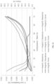
- Gaskets disclosed herein have enhanced electrical and thermal characteristics (e.g. , FIGS. 5-11 , etc .) as compared to conventional gaskets.
- an exemplary embodiment of a gasket disclosed herein is configured to have:
- gaskets disclosed herein have good compression and resiliency.
- a gasket is compressible to about 15% - 60% of its original (uncompressed) state ( e . g ., height in the Z-direction). When compressed less than 25% of its original (uncompressed) state, the gasket recovers to 90% to 100% of its original (uncompressed) state.
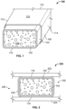
- FIGS. 1 and 2 illustrate an electrically and thermally conductive gasket 100 according to a non claimed example useful to understand the background of the invention.
- the electrically and thermally conductive gasket 100 includes a resilient core 102, a heat spreader 104 disposed along the resilient core 102.
- An electrically conductive layer 106 is disposed along and covers at least a portion of the heat spreader 104 such that the portion of the heat spreader 104 is between the resilient core 102 and the electrically conductive layer 106.
- the gasket 100 has a rectangular shape.
- the gasket 100 includes six sides 108, 110, 112, 114, 116, 118 defining a perimeter of the gasket 100.
- the sides 108, 110 form opposing end portions of the gasket 100
- the sides 112, 114 form opposing side portions
- the sides 116, 118 form opposing top and bottom portions.
- FIG. 1 illustrates the gasket 100 as being rectangular and including six sides, it should be apparent to those skilled in the art that other suitable shaped gaskets including more or less sides may be employed without departing from the scope of the present disclosure, as further explained below.
- the gasket 100 is compressible between one or more surfaces of components in a device.
- the core 102, the heat spreader 104, and the electrically conductive layer 106 are compressed when a force is applied to the gasket 100.
- the core 102 is generally resilient in nature thereby urging the core 102 to return to its original uncompressed or steady state. This resilient nature of the core 102 forces the electrically conductive layer 106 to press against and contact component surfaces when the gasket 100 is positioned between the component surfaces.
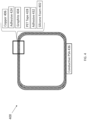
- FIG. 2 illustrates a device 200 including two components 202, 204 spaced apart by a gap 206.
- the gasket 100 is positioned in the gap 206 to form an electrically conductive path and a thermally conductive path between the components 202, 204.
- the opposing sides 116, 118 e.g., the opposing top and bottom portions of the gasket 100 contact the components 202, 204, respectively.
- an electrically conductive path is formed via the electrically conductive layer 106 contacting corresponding portions of the components 202, 204.
- the resilient core 102 urges the electrically conductive layer 106 to contact an electrically conductive portion of the component 202 and an electrically conductive portion of the component 204.
- the gasket 100 assists in shielding (e . g , electromagnetic interference (EMI) shielding including radio frequency shielding) and/or electrical grounding applications.
- EMI electromagnetic interference
- the gasket 100 forms a thermally conductive path between the components 202, 204 via the heat spreader 104 and the electrically conductive layer 106, which is in thermal communication with corresponding portions of the components 202, 204. Accordingly, a thermal path is formed from one component ( e . g ., the component 202) through the electrically conductive layer 106 and heat spreader 104 to the other component ( e.g ., the component 204).
- the heat spreader 104 covers all portions of the gasket 100.
- the heat spreader 104 covers the sides 112, 114, 116, 118, but does not cover the ends 108, 110 of the gasket 100.
- the heat spreader 104 extends completely around the resilient core 102 between the sides 108, 110 of the gasket 100.
- the electrically conductive layer 106 also does not cover the ends 108, 110 of the gasket 100.
- the resilient core 102 is exposed at the ends 108, 110 as shown in FIG. 1 .
- the heat spreader 104 and the electrically conductive layer 106 also cover the end 108, 110 of the gasket 100.
- the electrically conductive layer 106 covers all portions of the heat spreader 104.
- the heat spreader 104 covers all portions of the resilient core 102
- FIGS. 1 and 2 show the heat spreader 104 wrapped around each of the top, bottom, and sides of the resilient core 102, according to a non-claimed example useful to understand the background of the invention
- the heat spreader 104 is wrapped around an entire perimeter of the resilient core 102 defined by the core's top, bottom and sides.
- the electrically conductive layer 106 may also be wrapped around each of the top, bottom, and sides of the heat spreader 104.
- the electrically conductive layer 106 may be wrapped around an entire perimeter of the heat spreader 104 defined by the heat spreader's top, bottom and sides.
- FIG. 3 illustrates an electrically and thermally conductive gasket 300 according to a non-claimed example useful to understand the background of the invention.
- the gasket 300 includes a resilient core 302, a heat spreader 304, and an electrically conductive layer 306.
- the heat spreader 304 is disposed around a perimeter of the resilient core 302 defined by the four sides of the resilient core 302.
- the electrically conductive layer 306 is disposed around a perimeter defined by the four sides of the heat spreader 304, such that the heat spreader 304 is covered ( e.g ., protected, etc. ) by the electrically conductive layer 306.
- the heat spreader 304 and electrically conductive layer 306 are laminated together, and then wrapped around the resilient core 302.
- the gasket 300 includes a laminate that comprises the heat spreader 304 ( e . g , a flexible sheet of natural graphite and/or synthetic graphite, etc .) laminated with the electrically conductive layer 306 ( e.g ., copper foil, etc. ) .
- the laminate includes an adhesive 324 ( e.g ., pressure sensitive adhesive, etc. ) between and adhesively bonding the heat spreader 304 and the electrically conductive layer 306.
- the heat spreader 304, adhesive 324, and electrically conductive layer 306 are collectively wrapped together in the form of the laminate around the perimeter of the resilient core 302 (e.g ., silicone foam, polyurethane foam, other foam, other resilient material, etc .) defined by the plurality of sides of the resilient core 302.
- the resilient core 302 e.g ., silicone foam, polyurethane foam, other foam, other resilient material, etc .
- the gasket 300 further includes a tape 328 ( e.g ., PET film and adhesive, etc .), an adhesive 332, and an adhesive 336 ( e.g ., electrically conductive and thermally conductive pressure sensitive adhesive, etc. ) .
- the tape 328 is disposed along the bottom of the heat spreader 304, e . g ., to provide mechanical strength, abrasion resistance, and/or protection of the heat spreader 304 ( e.g ., inhibit graphite from flaking or breaking off, etc .).
- the adhesive 332 is disposed between the tape 328 and the resilient core 302, e . g ., for bonding the laminate to the resilient core 302.
- the adhesive 336 is along an outer portion ( e.g ., bottom, etc. ) of the gasket 100.
- the adhesive 336 is used for adhesively bonding, electrically connecting, and thermally connecting the gasket 100 to a corresponding surface of a component ( e.g ., component 200 in FIG. 2 , etc .).
- FIG. 4 illustrates an electrically and thermally conductive gasket 400 according to a non-claimed example of the present disclosure.
- the gasket 400 includes a silicone foam core 402, a graphite layer 404, and a copper layer 406.
- the graphite layer 404 is disposed around a perimeter of the silicone foam core 402 defined by the four sides of the silicone foam core 402.
- the copper layer 406 is disposed around a perimeter defined by the four sides of the heat spreader 404, such that the graphite layer is covered ( e.g ., protected, etc. ) by the copper layer 406.
- the graphite layer 404 and copper layer 406 are laminated together, and then wrapped around the silicone foam core 402.
- the gasket 400 includes a laminate that comprises the graphite layer 404 (e.g. , a flexible sheet of natural graphite and/or synthetic graphite, etc. ) laminated with the copper layer 406 ( e.g., copper foil, etc. ) .
- the laminate includes an adhesive 424 ( e.g ., pressure sensitive adhesive, etc .) between and adhesively bonding the graphite layer 404 and the copper layer 406.
- the graphite layer 404, adhesive 424, and copper layer 406 are collectively wrapped together in the form of the laminate around the perimeter of the silicone foam core 402 defined by the plurality of sides of the silicone foam core 402.
- the gasket 400 further includes a PET tape 428 (e.g. , PET film and adhesive, etc. ), an adhesive 432, and an electrically conductive and thermally conductive pressure sensitive adhesive (PSA) 436.
- the PET tape 428 is disposed along the bottom of the graphite layer 404, e.g. , to provide mechanical strength, abrasion resistance, and/or protection of the graphite layer 404 ( e.g. , inhibit graphite from flaking or breaking off, etc. ) .
- the adhesive 432 is disposed between the PET tape 428 and the silicone foam core 402, e.g. , for bonding the laminate to the silicone foam core 402.
- the conductive PSA 436 is along an outer portion ( e.g ., bottom, etc .) of the gasket 100.
- the conductive PSA 436 is used for adhesively bonding, electrically connecting, and thermally connecting the gasket 100 to a corresponding surface of a component ( e.g ., component 200 in FIG. 2 , etc .) .
- the copper layer 406 may comprise a copper foil having a thickness within a range from about 2 microns to about 20 microns.
- the copper foil may be about 5 microns thick.
- the adhesive 424 may comprise a pressure sensitive adhesive layer having a thickness within a range from about 1 micron to about 10 microns.
- the pressure sensitive adhesive layer may be about 3 microns thick.
- the graphite layer 404 may comprise a synthetic graphite sheet having a thickness within a range from about 9 microns to about 100 microns.
- the synthetic graphite sheet may be about 25 or 40 microns thick.
- the PET tape 428 may comprise a PET film and adhesive having a thickness within a range from about 5 microns to about 50 microns.
- the PET film and adhesive may be about 20 microns thick.
- the adhesive 432 may comprise an adhesive layer having a thickness within a range from about 30 microns to about 120 microns.
- the adhesive layer may be about 70 microns thick.
- the foam core 402 may comprise a silicone foam core ( e.g. , for 125 °C, etc.), polyurethane foam, other foam, other resilient material, etc.
- the foam core 402 may comprise a silicone or polyurethane foam having a thickness within a range from about 0.5 mm to about 60 mm.
- the conductive PSA 436 may comprise an acrylic or silicone PSA with thermal and electrical conductivity.
- the conductive PSA 436 may have a thickness within range from about 0.005 mm to about 0.15 mm.
- the heat spreader is wrapped (broadly, disposed) around all portions of the resilient core.
- the electrically conductive layer is wrapped (broadly, disposed) around all portions of the heat spreader.
- a laminate is formed of at least a heat spreader and an electrically conductive layer, and then wrapped around a resilient core.
- the resilient core, the heat spreader, and the electrically conductive layer combined have no more than a maximum of 900 parts per million chlorine, no more than a maximum of 900 parts per million bromine, and no more than a maximum of 1,500 parts per million total halogens such that the gasket is defined as halogen free.
- the gasket has a flame rating of V-0 under Underwriter's Laboratories (UL) Standard No. 94.
- any one of the gaskets disclosed herein are positionable between components in a device to thereby define an electrically conductive path and a thermally conductive path between the components.
- any one of the gaskets is positionable between the components 202, 204 of the device 200 of FIG. 2 and/or between other components in the device 200 and/or another suitable device.
- the components 202, 204 extend in substantially parallel planes and define the gap 206 therebetween.
- the gap 206 may have any suitable width.
- the gap 206 may be about 3 millimeters wide.
- the gap 206 may range from 1 to 2.5 millimeters wide, 3.5 to 7 millimeters wide, less than 1 millimeters wide, etc.
- the gasket 100 may have a similar width between the opposing sides 116, 118 when the gasket 100 ( e . g ., in a compressed state or uncompressed state) is between the components 202, 204.
- gaskets having opposing parallel extending sides may be most suitable for placing between the components 202, 204.
- Such gaskets may include generally cuboidal-shaped gaskets or another suitable shaped-gasket such as cube-shaped gaskets, parallelepiped-shaped gaskets, cylinder-shaped gaskets, frustum-shaped gaskets, etc.
- the gaskets may be another suitable shape depending on, e . g ., the arrangement of the components in the device.
- the devices disclosed herein may include electronic devices having one or more heat sources, shielding structures or components, heat removal/dissipation structures or components, and/or other suitable features.
- the shielding structures or components may include, e.g. , board level EMI shielding structures or components, etc.
- the heat removal/dissipation structures or components may include, e . g ., a heat spreader, a heat sink, a heat pipe, a device exterior case or housing, etc.
- a heat source may include any component or device that has a higher temperature than the gasket or otherwise provides or transfers heat to the gasket regardless of whether the heat is generated by the heat source or merely transferred through or via the heat source.
- a heat source may include one or more heat generating components or devices (e.g ., a CPU, die with underfill, semiconductor device, flip chip device, graphics processing unit (GPU), digital signal processor (DSP), multiprocessor system, integrated circuit, multi-core processor, etc .), a substrate (e.g ., a circuit board such as a printed circuit board, etc .), etc.
- heat generating components or devices e.g ., a CPU, die with underfill, semiconductor device, flip chip device, graphics processing unit (GPU), digital signal processor (DSP), multiprocessor system, integrated circuit, multi-core processor, etc .
- a substrate e.g ., a circuit board such as a printed circuit board, etc .
- the components disclosed herein may include any suitable components in the device.
- the components may include heat sources, shielding structures or components, heat removal/dissipation structures or components, etc. as explained above.
- the heat spreaders disclosed herein may include graphite ( e.g ., natural graphite, synthetic graphite, combinations thereof, etc. ), metallic (e.g ., copper, aluminum, gold, etc. and/or alloys thereof) component or structure and/or another suitable heat-spreading component or structure.
- the metallic component or structure may be made of copper, aluminum, gold, etc. and/or alloys thereof.
- the graphite may be formed one or more graphite sheets such as one or more Tgon TM 800 series natural graphite sheets ( e.g ., Tgon TM 805, 810, 820, etc. ), Tgon TM 8000 series graphite sheets, Tgon TM 9000 series synthetic graphite sheets ( e.g.
- the metallic component or structure may include a metal foil, a multi-laminate structure, etc.
- the multi-laminate structure may include a multi-laminate structure of metal and plastic.
- the heat spreader may comprise a flexible sheet of natural and/or synthetic graphite.
- the graphite may comprise a graphite sheet (e.g ., Tgon TM 9000 series graphite sheets, etc. ) from Laird Technologies, such as a Tgon TM 9017, Tgon TM 9025, Tgon TM 9040, Tgon TM 9070, and/or Tgon TM 9100 synthetic graphite sheet.
- Table 1 below includes additional details about Tgon TM 9000 series synthetic graphite from Laird Technologies.
- the graphite sheet(s) may include one or more Tgon TM 9000 series graphite sheets that comprise synthetic graphite thermal interface materials having a carbon in-plane mono-crystal structure and that are ultra-thin, light-weight, flexible and offer excellent in-plane thermal conductivity.
- Tgon TM 9000 series graphite sheets are useful for a variety of heat spreading applications where in-plane thermal conductivity dominates and in limited spaces.
- Tgon TM 9000 series graphite sheets may have a thermal conductivity from about 500 W/mK to about 1900 W/mK, may help reduce hot spots and protect sensitive areas, may enable slim device designs due to the ultra-thin sheet thickness of about 17 micrometers to about 100 micrometers, may be light weight ( e.g ., density from about 2.05 to 2.25 g/cm 3 for a thickness of 17 micrometers or 25 micrometers, etc. ), may be flexible and able to withstand more than 10,000 times bending with radius of 5 millimeters.
- the resilient cores disclosed herein may include any suitable material.
- the resilient cores may be formed of a foam material (e.g. , a silicone foam material, a polymeric elastomer material, a cellular polymeric foam such as an open cell foam, a closed cell foam, a neoprene foam, a urethane foam ( e.g. , a polyester foam, a polyether foam, a combination thereof, etc. ), a polyurethane foam, etc. ), a silicone rubber material, etc.
- the resilient cores may be extruded.
- the resilient cores may be electrically conductive and/or thermally conductive.
- the resilient cores may include electrically conductive particles (e.g ., fillers, etc .) dispersed therein.
- one or more additives or fillers may be added to the resilient material used for the resilient core.
- a wide variety of additives or fillers may be incorporated into the resilient core material (e.g ., silicone foam, polyurethane foam, etc. ) to tailor, modify, and/or functionally tune property(ies) of the resilient core.
- the fillers may include functional nanoparticles, electrically-conductive fillers, thermally-conductive fillers, EMI or microwave absorbing fillers, magnetic fillers, dielectric fillers, coated fillers, combinations thereof, etc.
- Example fillers include carbon black, boron nitride, nickel cobalt, carbonyl iron, iron silicide, iron particles, iron-chrome compounds, silver, an alloy containing 85% iron, 9.5% silicon and 5.5% aluminum, an alloy containing about 20% iron and 80% nickel, ferrites, magnetic alloys, magnetic powders, magnetic flakes, magnetic particles, nickel-based alloys and powders, chrome alloys, aluminum oxide, copper, zinc oxide, alumina, aluminum, graphite, ceramics, silicon carbide, manganese zinc, fiberglass, combinations thereof, etc.
- the fillers may comprise one or more of granules, spheroids, microspheres, ellipsoids, irregular spheroids, strands, flakes, powder, and/or a combination of any or all of these shapes.
- exemplary embodiments may also include different grades (e. g., different sizes, different purities, different shapes, etc. ) of the same (or different) fillers.
- the electrically conductive layers disclosed herein may include one or more electrically conductive foils (e.g ., a copper foil, etc. ), a metallized and/or plated fabrics ( e.g ., nickel-copper plated nylon, etc .), etc.
- the electrically conductive layers may have metal plating or electrically-conductive ink or paste (e.g. , silver ink or paste, etc .) applied ( e.g ., plated, printed, etc .) onto either or both surfaces of the films.
- the electrically conductive layers may include metal-plated polyimide fabrics, metallized-plated polyimide fabrics, poly-foil (e.g ., metal foil laminated to polyester or PET, polypropylene (PP), polyethylene (PE), other polymer, etc .), etc.
- the electrically conductive layers may comprise Mylar ® polyester films, other polyester films, polyimide (PI) films, PET films, polyethylene naphthalate (PEN) films, etc.
- the heat spreaders, the electrically conductive layers and/or the resilient cores may be adhered together.
- the gaskets may include an adhesive to bond at least two of these layers together.
- the adhesive may be an electrically conductive adhesive such as a silicone-based conductive adhesive ( e.g. , a silicone PSA, etc. ).
- the adhesive may include a double-sided tape ( e.g ., one or more strips) with or without a metallized ( e.g ., nickel, copper, etc. ) film.
- the adhesive may include adhesives such as solvent-based polyester adhesives, epoxy-based adhesives, hot melt adhesives, combinations thereof, etc.
- exemplary embodiments copper-over-graphite-over-foam (COGOF) electrically and thermally conductive gaskets that are configured to provide thermal transfer performance in the form of a wrapped compressible foam gasket and that include an outside copper foil or wrap for electrical conductivity. Such exemplary embodiments are configured to combine the thermal transfer performance associated with a graphite sheet or wrap and the repeatable compression and rebound of a foam core.
- the electrically and thermally conductive gasket include a silicone foam core for lower compression force and UL V0 flammability rating.
- Exemplary embodiments disclosed herein include or provide one or more (but not necessarily any or all) of the advantages or features listed below.
Landscapes
- Engineering & Computer Science (AREA)
- General Engineering & Computer Science (AREA)
- Mechanical Engineering (AREA)
- Microelectronics & Electronic Packaging (AREA)
- Physics & Mathematics (AREA)
- Thermal Sciences (AREA)
- Shielding Devices Or Components To Electric Or Magnetic Fields (AREA)
- Cooling Or The Like Of Electrical Apparatus (AREA)
- Gasket Seals (AREA)
- Cooling Or The Like Of Semiconductors Or Solid State Devices (AREA)
Claims (13)
- Eine elektrisch und thermisch leitende Dichtung (100, 300, 400), umfassend:einen elastischen Kern (102, 302, 402), der Schaumstoff umfasst, der elastische Kern hat mehrere Seiten (108, 110, 112, 114, 116, 118), einschließlich zwei gegenüberliegender Seiten (116, 118) und Seiten (108, 110, 112, 114), die die beiden gegenüberliegenden Seiten des elastischen Kerns verbinden;einen Wärmespreizer (104, 304, 404), der eine Graphitplatte umfasst, der entlang aller der mehreren Seiten des elastischen Kerns angeordnet ist und alle der mehreren Seiten des elastischen Kerns abdeckt; undeine elektrisch leitende Schicht (106, 306, 406), die entlang aller der mehreren Seiten des Wärmespreizers angeordnet ist, der alle der mehreren Seiten (108, 110, 112, 114, 116, 118) des elastischen Kerns abdeckt, so dass sich der Wärmespreizer zwischen dem elastischen Kern und der elektrisch leitenden Schicht befindet;wobei die elektrisch leitfähige Schicht ausgebildet ist, um mechanische Festigkeit, Abriebfestigkeit und Schutz für den von der elektrisch leitenden Schicht bedeckten Wärmespreizer zu gewährleisten und um der Dichtung elektrische Leitfähigkeit und zusätzliche Wärmeübertragung zu verleihen;wobei die Dichtung so ausgebildet ist, dass sie zwischen ersten und zweiten Oberflächen (202, 204) von Komponenten in einer Vorrichtung (200) positioniert und/oder zusammengedrückt wird,wobei die beiden gegenüberliegenden Seiten (116, 118) der Dichtung, einschließlich der elektrisch leitende Schicht, jeweils die erste und zweite Oberfläche (202, 204) berühren, um dadurch einen elektrisch leitenden Pfad und einen thermisch leitenden Pfad zwischen der ersten und zweiten Oberfläche zu definieren; undwobei die elektrisch leitende Schicht so ausgebildet ist, dass sie ein Abblättern oder Abbrechen des Graphits von der Graphitschicht verhindert.
- Die elektrisch und thermisch leitfähige Dichtung nach Anspruch 1, wobei:der Wärmespreizer eine flexible Graphitplatte umfasst, die um alle der mehreren Seiten des elastischen Kerns gewickelt ist;die elektrisch leitfähige Schicht eine Kupferfolie umfasst, die um alle der mehreren Seiten der flexiblen Graphitplatte gewickelt ist:wobei die Kupferfolie in Dickenrichtung eine höhere Wärmeleitfähigkeit als die flexible Graphitplatte aufweist; unddie flexible Graphitplatte eine höhere Wärmeleitfähigkeit in der Ebene als die Kupferfolie aufweist.
- Die elektrisch und thermisch leitfähige Dichtung nach Anspruch 1 oder 2, wobei die Dichtung (300, 400) ein Laminat umfasst, das den Wärmespreizer (304, 404) beinhaltet, der zusammen mit der elektrisch leitfähigen Schicht (306, 406) laminiert ist; und wobei das Laminat, das den Wärmespreizer und die elektrisch leitfähige Schicht umfasst, die zusammen laminiert sind, gemeinsam um alle der mehreren Seiten des elastischen Kerns gewickelt ist.
- Die elektrisch und thermisch leitfähige Dichtung nach Anspruch 1, wobei:die elektrisch leitfähige Schicht (306, 406) eine Kupferfolie umfasst;die Dichtung (300, 400) ein Laminat umfasst, das die Graphitplatte beinhaltet, die mit der Kupferfolie zusammen laminiert ist, wobei das Laminat, das die Graphitplatte unddie Kupferfolie umfasst, die zusammen laminiert sind, gemeinsam um alle der mehreren Seiten des elastischen Kerns gewickelt ist;die Kupferfolie weist eine höhere Wärmeleitfähigkeit als die Graphitplatte in Dickenrichtung auf; unddie Graphitplatte weist eine höhere Wärmeleitfähigkeit in der Ebene auf als die Kupferfolie.
- Die elektrisch und thermisch leitfähige Dichtung nach einem der Ansprüche 3 oder 4, wobei:das Laminat einen druckempfindlichen Klebstoff (324, 424) zwischen dem Wärmespreizer und der elektrisch leitfähigen Schicht aufweist und diese klebend verbindet; unddie Dichtung einen Klebstoff (332, 432) zwischen dem Laminat und dem elastischen Kern aufweist und diese klebend verbindet.
- Die elektrisch und thermisch leitfähige Dichtung nach Anspruch 3 oder 4,wobei das Laminat einen druckempfindlichen Klebstoff (324, 424) zwischen dem Wärmespreizer und der elektrisch leitfähigen Schicht enthält und diese klebend verbindet; unddie Dichtung enthält: ein Band (328) oder PET-Band (428), das entlang des Wärmespreizers angeordnet ist; und einen Klebstoff (332, 432), der zwischen dem Band oder PET-Band und dem elastischen Kern angeordnet ist;wobei das Band (328) oder PET-Band (428) eine Polyethylenterephthalat-Folie und einen Klebstoff zwischen der Polyethylenterephthalat-Folie und dem Wärmespreizer enthält; undwobei der Klebstoff (332, 432) zwischen der Polyethylenterephthalat-Folie und dem elastischen Kern angeordnet ist und diese klebend verbindet.
- Die elektrisch und thermisch leitfähige Dichtung nach einem der Ansprüche 1 bis 6, wobei die Dichtung einen elektrisch und thermisch leitfähigen Klebstoff umfasst, der ein elektrisch und thermisch leitfähiger, druckempfindlicher Klebstoff ist entlang des äußeren Abschnitts der Dichtung, um die Dichtung klebend mit der zweiten Oberfläche zu verbinden.
- Die elektrisch und thermisch leitfähige Dichtung nach einem der Ansprüche 1 bis 7, wobei:der Wärmespreizer eine natürliche und/oder synthetische Graphitplatte umfasst;die elektrisch leitfähige Schicht eine Kupferfolie umfasst, die um alle der mehreren Seiten der natürlichen oder synthetischen Graphitplatte gewickelt ist;der elastische Kern Silikonschaum oder Polyurethanschaum umfasst und die Kupferfolie so konfiguriert ist, dass sie verhindert, dass Graphit von dem Teil der natürlichen und/oder synthetischen Graphitplatte abblättert oder abbricht, der von der Kupferfolie bedeckt ist.
- Die elektrisch und thermisch leitfähige Dichtung nach einem der Ansprüche 1 bis 8, wobei:
die elektrisch leitfähige Schicht eine höhere Wärmeleitfähigkeit als der Wärmespreizer in Dickenrichtung aufweist; und der Wärmespreizer eine höhere Wärmeleitfähigkeit in der Ebene aufweist als die elektrisch leitfähige Schicht. - Die elektrisch und thermisch leitfähige Dichtung nach einem der Ansprüche 1 bis 9, wobei: der elastische Kern, der Wärmespreizer und die elektrisch leitfähige Schicht zusammen nicht mehr als 900 ppm Chlor, nicht mehr als 900 ppm Brom und insgesamt nicht mehr als 1.500 ppm Halogene enthalten, sodass die Dichtung als halogenfrei definiert wird; und
die Dichtung eine Flammbeständigkeitsklasse von V-0 gemäß Underwriter's Laboratories (UL) Standard Nr. 94 aufweist. - Die elektrisch und thermisch leitfähige Dichtung nach einem der Ansprüche 1 bis 10, wobei die Dichtung so konfiguriert ist, dass sie aufweist:ein maximales Kompressionsverhältnis in einem Bereich von etwa 40 % bis etwa 70 %;eine Abschirmwirksamkeit von mehr als 60 Dezibel für Frequenzen in einem Bereich von 30 Megahertz bis 18 Gigahertz bei einem Kompressionsverhältnis von 50 %; undeine Wärmeleitfähigkeit von mehr als 2 W/mK bei einem Kompressionsverhältnis von 25 % und einer Dichtungshöhe von 1 Millimeter oder mehr.
- Die elektrisch und thermisch leitfähige Dichtung nach einem der Ansprüche 1 bis 11, wobei die Dichtung so konfiguriert ist, dass sie aufweist:eine Z-Achse, wobei die Z-Achse der Kompressionsrichtung der Dichtung entspricht;einen elektrischen Widerstand auf der Z-Achse von weniger als 0,04 Ohm bei einem Kompressionsverhältnis in einem Bereich von etwa 0 % Kompression bis etwa 70 % Kompression;einen elektrischen Widerstand auf der Z-Achse von weniger als 0,01 Ohm bei einem Kompressionsverhältnis in einem Bereich von etwa 5 % Kompression bis etwa 70 % Kompression bei einer Dichtungshöhe von 10 Millimetern oder weniger;einen thermischen Widerstand von weniger als 8 cm2 °C/W bei einem Kompressionsverhältnis von 25 % und einer Dichtungshöhe von 10 Millimetern oder weniger; undeinen thermischen Widerstand von weniger als 8 cm2 °C/W bei einem Kompressionsverhältnis in einem Bereich von etwa 15 % bis 75 % bei einer Dichtungshöhe von 10 Millimetern oder weniger.
- Die elektrisch und thermisch leitfähige Dichtung nach einem der Ansprüche 1 bis 12, wobei:die Dichtung so konfiguriert ist, dass sie auf etwa 15 % bis 60 % ihres ursprünglichen (unkomprimierten) Zustands komprimierbar ist; unddie Dichtung so konfiguriert ist, dass sie komprimierbar ist, sodass sie, wenn sie auf weniger als 25 % ihres ursprünglichen (unkomprimierten) Zustands komprimiert wird, sich auf 90 % bis 100 % ihres ursprünglichen (unkomprimierten) Zustands zurückbildet.
Applications Claiming Priority (3)
| Application Number | Priority Date | Filing Date | Title |
|---|---|---|---|
| CN202011434499.9A CN114628055A (zh) | 2020-12-10 | 2020-12-10 | 导电导热垫圈、制造导电导热垫圈的方法、电装置 |
| CN202022939691.5U CN214012524U (zh) | 2020-12-10 | 2020-12-10 | 导电导热垫圈、电装置 |
| US17/534,009 US12209664B2 (en) | 2020-12-10 | 2021-11-23 | Electrically and thermally conductive gaskets |
Publications (2)
| Publication Number | Publication Date |
|---|---|
| EP4013203A1 EP4013203A1 (de) | 2022-06-15 |
| EP4013203B1 true EP4013203B1 (de) | 2024-07-31 |
Family
ID=79231045
Family Applications (1)
| Application Number | Title | Priority Date | Filing Date |
|---|---|---|---|
| EP21212733.6A Active EP4013203B1 (de) | 2020-12-10 | 2021-12-07 | Elektrisch und thermisch leitende dichtungen |
Country Status (6)
| Country | Link |
|---|---|
| US (1) | US12486900B2 (de) |
| EP (1) | EP4013203B1 (de) |
| JP (2) | JP2022092603A (de) |
| KR (1) | KR102623805B1 (de) |
| DE (1) | DE202021106695U1 (de) |
| TW (1) | TWM630084U (de) |
Families Citing this family (1)
| Publication number | Priority date | Publication date | Assignee | Title |
|---|---|---|---|---|
| KR102620906B1 (ko) * | 2023-07-11 | 2024-01-04 | 주식회사 이송이엠씨 | 열 확산 시트가 내재된 솔더링용 열/전기 전도성 탄성체및 그 제조 방법 |
Family Cites Families (88)
| Publication number | Priority date | Publication date | Assignee | Title |
|---|---|---|---|---|
| US2116000A (en) * | 1935-03-08 | 1938-05-03 | Victor Mfg & Gasket Co | Coating for gaskets and the like |
| US3648965A (en) * | 1970-08-24 | 1972-03-14 | Polycast Technology Corp The | Gasket for plastic casting |
| US3729205A (en) * | 1971-01-07 | 1973-04-24 | M Kwok | Gaskets |
| EP0128154B1 (de) | 1982-12-16 | 1986-10-22 | Hasler AG | Mit wärmeleitfähiger paste oder flüssigkeit gefüllter flachbeutel |
| JPH065109B2 (ja) * | 1986-01-24 | 1994-01-19 | 日本ピラ−工業株式会社 | ガスケツト用素材 |
| US4857668A (en) * | 1988-04-15 | 1989-08-15 | Schlegel Corporation | Multi-function gasket |
| US5028739A (en) * | 1989-04-13 | 1991-07-02 | Chomerics, Inc. | EMI/REI shielding gasket |
| US5045635A (en) * | 1989-06-16 | 1991-09-03 | Schlegel Corporation | Conductive gasket with flame and abrasion resistant conductive coating |
| CA2129073C (en) | 1993-09-10 | 2007-06-05 | John P. Kalinoski | Form-in-place emi gaskets |
| WO1997008928A1 (en) | 1995-08-25 | 1997-03-06 | Parker-Hannifin Corporation | Emi shielding gasket having a consolidated conductive sheathing |
| JPH10242354A (ja) | 1997-02-24 | 1998-09-11 | Matsushita Electric Ind Co Ltd | 熱伝導部材およびそれを用いた電子装置 |
| US6075205A (en) | 1997-10-27 | 2000-06-13 | Parker-Hannifin Corporation | Tubular extrusion gasket profile exhibiting a controlled deflection response for improved environmental sealing and EMI shielding |
| US6248393B1 (en) * | 1998-02-27 | 2001-06-19 | Parker-Hannifin Corporation | Flame retardant EMI shielding materials and method of manufacture |
| US6477061B1 (en) | 1998-03-23 | 2002-11-05 | Amesbury Group, Inc. | I/O port EMI shield |
| WO2000023513A1 (en) * | 1998-10-22 | 2000-04-27 | Parker-Hannifin Corporation | Intumescent, flame retardant pressure sensitive adhesive composition for emi shielding applications |
| US6241005B1 (en) | 1999-03-30 | 2001-06-05 | Veeco Instruments, Inc. | Thermal interface member |
| AU1751001A (en) | 1999-07-30 | 2001-02-19 | Amesbury Group, Inc. | Method and apparatus for manufacturing a flame retardant emi gasket |
| WO2001024596A1 (en) | 1999-09-30 | 2001-04-05 | Instrument Specialties Co., Inc. | Emi/rfi shielding device and gasket and method of making the same |
| US6309742B1 (en) | 2000-01-28 | 2001-10-30 | Gore Enterprise Holdings, Inc. | EMI/RFI shielding gasket |
| US6482520B1 (en) | 2000-02-25 | 2002-11-19 | Jing Wen Tzeng | Thermal management system |
| DE60128727T2 (de) | 2001-01-22 | 2008-01-31 | PARKER HANNIFIN Corporation, Cleveland | Rückstandsfrei ablösbares thermisches verbindungsstück mit phasenübergangsmaterial |
| US7166912B2 (en) | 2001-04-05 | 2007-01-23 | Advanced Energy Technology Inc. | Isolated thermal interface |
| JP4706125B2 (ja) | 2001-05-24 | 2011-06-22 | パナソニック株式会社 | 機能ユニットの放熱緩衝構造を備えた情報処理装置 |
| US20050003200A1 (en) | 2001-08-31 | 2005-01-06 | Julian Norley | Resin-impregnated flexible graphite articles |
| US6777086B2 (en) | 2001-08-31 | 2004-08-17 | Julian Norley | Laminates prepared from impregnated flexible graphite sheets |
| WO2003030610A1 (en) | 2001-10-02 | 2003-04-10 | Parker Hannifin Corporation | Emi shielding gasket construction |
| US20030128519A1 (en) * | 2002-01-08 | 2003-07-10 | International Business Machine Corporartion | Flexible, thermally conductive, electrically insulating gap filler, method to prepare same, and method using same |
| US6919504B2 (en) | 2002-12-19 | 2005-07-19 | 3M Innovative Properties Company | Flexible heat sink |
| US7063127B2 (en) | 2003-09-18 | 2006-06-20 | International Business Machines Corporation | Method and apparatus for chip-cooling |
| US7303820B2 (en) | 2003-10-14 | 2007-12-04 | Graftech International Holdings Inc. | Heat spreader for display device |
| ES2690773T3 (es) | 2003-11-04 | 2018-11-22 | Neograf Solutions, Llc | Solución térmica tipo sándwich |
| US7292441B2 (en) | 2003-11-25 | 2007-11-06 | Advanced Energy Technology Inc. | Thermal solution for portable electronic devices |
| US6943288B1 (en) | 2004-06-04 | 2005-09-13 | Schlegel Systems, Inc. | EMI foil laminate gasket |
| US7161809B2 (en) | 2004-09-15 | 2007-01-09 | Advanced Energy Technology Inc. | Integral heat spreader |
| US7306847B2 (en) | 2005-01-28 | 2007-12-11 | Graftech International Holdings Inc. | Heat spreader for display device |
| US8545974B2 (en) | 2005-02-09 | 2013-10-01 | Laird Technologies, Inc. | Flame retardant EMI shields |
| JP4695655B2 (ja) * | 2005-02-16 | 2011-06-08 | パーカー−ハニフイン・コーポレーシヨン | 難燃性emi遮蔽ガスケット |
| PL1701605T3 (pl) | 2005-03-11 | 2008-07-31 | Mtc Micro Tech Components Gmbh | Taśma uszczelniająca przed promieniowaniem elektromagnetycznym wysokiej częstotliwości |
| FR2883995A1 (fr) | 2005-04-04 | 2006-10-06 | Vernet Sa | Element thermostatique, notamment pour thermostat de circuit de refroidissement, et procede de fabrication d'un tel element |
| US20060225874A1 (en) | 2005-04-11 | 2006-10-12 | Shives Gary D | Sandwiched thermal article |
| CN101248714B (zh) | 2005-05-19 | 2010-06-09 | 派克汉尼芬公司 | 用于电磁干扰屏蔽的条带垫圈 |
| US7889502B1 (en) | 2005-11-04 | 2011-02-15 | Graftech International Holdings Inc. | Heat spreading circuit assembly |
| JP2007184392A (ja) | 2006-01-06 | 2007-07-19 | Taika:Kk | 熱伝導構造体、それを用いた放熱部材及び電子機器 |
| US8217512B1 (en) | 2006-07-13 | 2012-07-10 | EADS North America, Inc. | Thermal interface device |
| US20080157915A1 (en) * | 2007-01-03 | 2008-07-03 | Ethan Lin | Flame retardant, electrically-conductive pressure sensitive adhesive materials and methods of making the same |
| KR20090028283A (ko) | 2007-09-14 | 2009-03-18 | 주식회사 유비텍 | 다층 구조의 도전성 엘라스토머 |
| US7763810B2 (en) | 2007-11-07 | 2010-07-27 | Laird Technologies, Inc. | Fabric-over-foam EMI gaskets having transverse slits and related methods |
| US20100142154A1 (en) | 2008-12-04 | 2010-06-10 | Microvision, Inc. | Thermally Dissipative Enclosure Having Shock Absorbing Properties |
| KR100953679B1 (ko) | 2009-06-15 | 2010-04-20 | 두성산업 주식회사 | 방열재 및 그 제조 방법 |
| US8223986B2 (en) | 2009-11-19 | 2012-07-17 | Apple Inc. | Electronic device and external equipment with digital noise cancellation and digital audio path |
| US20120033384A1 (en) | 2010-08-06 | 2012-02-09 | Pillai Unnikrishnan G | Graphite wrapped heat spreading pillow |
| US8498127B2 (en) | 2010-09-10 | 2013-07-30 | Ge Intelligent Platforms, Inc. | Thermal interface material for reducing thermal resistance and method of making the same |
| US20190162306A9 (en) * | 2011-06-17 | 2019-05-30 | The Patent Well LLC | Polyurea gasket and gasket tape and a method of making and using the same |
| US9756764B2 (en) | 2011-08-29 | 2017-09-05 | Aerovironment, Inc. | Thermal management system for an aircraft avionics bay |
| US9067287B2 (en) | 2011-08-29 | 2015-06-30 | Aerovironment, Inc. | Method of manufacturing a heat transfer system for aircraft structures |
| NZ595493A (en) | 2011-09-30 | 2014-04-30 | Hieff Engine Company Ltd | Internal combustion engine |
| KR101245164B1 (ko) | 2012-06-29 | 2013-03-18 | 주식회사 이송이엠씨 | 열전도성 폼 가스켓 |
| DE212013000167U1 (de) * | 2012-07-28 | 2015-03-06 | Laird Technologies, Inc. | Mit metallischem Film überzogener Schaumstoffkontakt |
| KR101228603B1 (ko) * | 2012-07-31 | 2013-01-31 | 엘지전자 주식회사 | 그라파이트 밀폐형 열전도성 탄성 가스켓 |
| KR101256397B1 (ko) * | 2012-09-28 | 2013-04-25 | 주식회사 이송이엠씨 | 그라파이트 밀폐형 전기/열 전도성 탄성가스켓 |
| KR101243647B1 (ko) | 2012-10-05 | 2013-03-19 | (주)메인일렉콤 | 그라파이트 페이퍼를 이용하여 방열 효율을 극대화시킨 쿠션부재 및 그 제조방법 |
| JP2014099558A (ja) * | 2012-11-15 | 2014-05-29 | Toshiba Corp | グラウンディングガスケットおよび電子機器 |
| US9226433B2 (en) * | 2013-03-15 | 2015-12-29 | Laird Technologies, Inc. | Selectively conductive EMI gaskets |
| US9389029B2 (en) | 2013-09-30 | 2016-07-12 | Apple Inc. | Heat transfer structure |
| JP5490957B1 (ja) | 2013-10-25 | 2014-05-14 | 清二 加川 | 放熱フィルム、並びにその製造方法及び装置 |
| US20150301568A1 (en) | 2014-04-18 | 2015-10-22 | Laird Technologies, Inc. | Thermal Solutions and Methods for Dissipating Heat from Electronic Devices Using the Same Side of an Anisotropic Heat Spreader |
| WO2016003468A1 (en) * | 2014-07-03 | 2016-01-07 | Apple Inc. | Thermal gap pad |
| KR102241412B1 (ko) | 2014-08-19 | 2021-04-19 | 삼성디스플레이 주식회사 | 복합 시트 및 이를 포함하는 표시장치 |
| CN104320954B (zh) | 2014-10-20 | 2017-05-17 | 胡孟 | 一种含热熔导热膜的导热衬垫及其制备装置 |
| US20160262291A1 (en) * | 2015-03-06 | 2016-09-08 | Laird Technologies, Inc. | Gasket having two regions of foam densities |
| WO2017087969A1 (en) | 2015-11-19 | 2017-05-26 | Boyd Corporation | Densified foam for thermal insulation in electronic devices |
| GB2545212B (en) | 2015-12-09 | 2018-08-15 | Jaguar Land Rover Ltd | Powertrain system having thermally insulating panel for a vehicle |
| CN107027254B (zh) | 2016-02-02 | 2020-12-25 | 3M创新有限公司 | 可压缩衬垫、其制备方法和包含其的电子产品 |
| CN105667041B (zh) * | 2016-02-24 | 2018-02-02 | 深圳市金晖科技有限公司 | 一种石墨导热泡棉及其制备工艺 |
| US10389397B2 (en) * | 2016-07-26 | 2019-08-20 | Laird Technologies, Inc. | Small form-factor pluggable (SFP) transceivers |
| US10965333B2 (en) * | 2016-07-26 | 2021-03-30 | Laird Technologies, Inc. | Thermal management assemblies suitable for use with transceivers and other devices |
| TWI659828B (zh) | 2016-07-27 | 2019-05-21 | 日商Jx金屬股份有限公司 | 附散熱用金屬材之結構物、印刷電路板、電子機器及散熱用金屬材 |
| KR102122450B1 (ko) | 2016-08-26 | 2020-06-12 | 주식회사 엘지화학 | 방열재, 이를 제조하는 방법 및 방열재를 포함하는 배터리 모듈 |
| US10262916B2 (en) | 2016-12-20 | 2019-04-16 | Jones Tech Inc. | Foldable graphite heat spreader |
| US20180199460A1 (en) | 2017-01-07 | 2018-07-12 | Jones Tech Inc. | Array of graphite over foam having multi-cross section to increase heat transfer ability in an electronic device |
| DK3583622T3 (da) | 2017-02-20 | 2021-05-25 | Lohmann Gmbh & Co Kg | Indretning til varmespredning og elektrisk isolering |
| CN206562400U (zh) | 2017-02-24 | 2017-10-17 | 深圳市金晖科技有限公司 | 一种cpu散热用导热泡棉垫片 |
| CN106753018A (zh) | 2017-02-24 | 2017-05-31 | 深圳市金晖科技有限公司 | 一种cpu散热用导热泡棉垫片的结构和制造工艺 |
| CN107105604A (zh) | 2017-05-21 | 2017-08-29 | 昆山佑威光电材料有限公司 | 一种快速导热防震泡棉条 |
| JP6488040B1 (ja) | 2018-03-20 | 2019-03-20 | 大王製紙株式会社 | テープタイプ使い捨ておむつ |
| US10881022B2 (en) * | 2018-07-11 | 2020-12-29 | Trw Automotive U.S. Llc | Thermal interface assembly |
| KR102079031B1 (ko) * | 2019-10-29 | 2020-02-19 | 인동전자(주) | 열 전도성 탄성 가스켓. |
| US12209664B2 (en) * | 2020-12-10 | 2025-01-28 | Laird Technologies (Shenzhen) Ltd. | Electrically and thermally conductive gaskets |
-
2021
- 2021-12-07 EP EP21212733.6A patent/EP4013203B1/de active Active
- 2021-12-08 JP JP2021199602A patent/JP2022092603A/ja active Pending
- 2021-12-08 TW TW110214614U patent/TWM630084U/zh unknown
- 2021-12-08 DE DE202021106695.4U patent/DE202021106695U1/de active Active
- 2021-12-10 KR KR1020210176653A patent/KR102623805B1/ko active Active
-
2023
- 2023-05-29 JP JP2023001826U patent/JP3243919U/ja active Active
-
2024
- 2024-10-01 US US18/903,785 patent/US12486900B2/en active Active
Also Published As
| Publication number | Publication date |
|---|---|
| KR20220082773A (ko) | 2022-06-17 |
| US12486900B2 (en) | 2025-12-02 |
| JP3243919U (ja) | 2023-09-29 |
| JP2022092603A (ja) | 2022-06-22 |
| EP4013203A1 (de) | 2022-06-15 |
| DE202021106695U1 (de) | 2022-01-11 |
| KR102623805B1 (ko) | 2024-01-10 |
| US20250020209A1 (en) | 2025-01-16 |
| TWM630084U (zh) | 2022-08-01 |
| TW202223925A (zh) | 2022-06-16 |
Similar Documents
| Publication | Publication Date | Title |
|---|---|---|
| US12209664B2 (en) | Electrically and thermally conductive gaskets | |
| US11483948B2 (en) | Thermal interface materials including memory foam cores | |
| US10477739B2 (en) | Thermally-conductive electromagnetic interference (EMI) absorbers positioned or positionable between board level shields and heat sinks | |
| US6705388B1 (en) | Non-electrically conductive thermal dissipator for electronic components | |
| CA2738098C (en) | Electrically-conductive foam emi shield | |
| US9968004B2 (en) | Thermal interface materials including electrically-conductive material | |
| US20120061135A1 (en) | Compliant multilayered thermally-conductive interface assemblies having emi shielding properties | |
| KR101544587B1 (ko) | 열전도성 접착층을 포함하는 전자파 차단 필름 및 그 제조 방법. | |
| KR20110076875A (ko) | 열 전도성 젤 팩 | |
| CN214012524U (zh) | 导电导热垫圈、电装置 | |
| US12486900B2 (en) | Electrically and thermally conductive gaskets | |
| US20120181080A1 (en) | Combination glass/ceramic particles for emi shielding | |
| JP5894612B2 (ja) | 熱伝導性emi抑制構造 | |
| TWI907580B (zh) | 導電導熱墊圈 | |
| CN114628055A (zh) | 导电导热垫圈、制造导电导热垫圈的方法、电装置 | |
| CN210432257U (zh) | 导电且导热的复合件及包括该复合件的电子装置 | |
| EP1593293B1 (de) | Kombinierte metall- und kunststoff-emi-abschirmung | |
| WO1999025022A1 (en) | Non-electrically conductive thermal dissipator for electronic components | |
| KR20170044624A (ko) | 열전도성 emi 억제 조성 | |
| CN111935945A (zh) | 导电且导热的复合件 | |
| ES2367631T3 (es) | Pantalla emi de metal y de plástico en combinación. | |
| KR20150086586A (ko) | 열전도성 emi 억제 조성 |
Legal Events
| Date | Code | Title | Description |
|---|---|---|---|
| PUAI | Public reference made under article 153(3) epc to a published international application that has entered the european phase |
Free format text: ORIGINAL CODE: 0009012 |
|
| STAA | Information on the status of an ep patent application or granted ep patent |
Free format text: STATUS: THE APPLICATION HAS BEEN PUBLISHED |
|
| AK | Designated contracting states |
Kind code of ref document: A1 Designated state(s): AL AT BE BG CH CY CZ DE DK EE ES FI FR GB GR HR HU IE IS IT LI LT LU LV MC MK MT NL NO PL PT RO RS SE SI SK SM TR |
|
| STAA | Information on the status of an ep patent application or granted ep patent |
Free format text: STATUS: REQUEST FOR EXAMINATION WAS MADE |
|
| 17P | Request for examination filed |
Effective date: 20221208 |
|
| RBV | Designated contracting states (corrected) |
Designated state(s): AL AT BE BG CH CY CZ DE DK EE ES FI FR GB GR HR HU IE IS IT LI LT LU LV MC MK MT NL NO PL PT RO RS SE SI SK SM TR |
|
| STAA | Information on the status of an ep patent application or granted ep patent |
Free format text: STATUS: EXAMINATION IS IN PROGRESS |
|
| 17Q | First examination report despatched |
Effective date: 20230307 |
|
| GRAP | Despatch of communication of intention to grant a patent |
Free format text: ORIGINAL CODE: EPIDOSNIGR1 |
|
| STAA | Information on the status of an ep patent application or granted ep patent |
Free format text: STATUS: GRANT OF PATENT IS INTENDED |
|
| INTG | Intention to grant announced |
Effective date: 20240405 |
|
| RAP3 | Party data changed (applicant data changed or rights of an application transferred) |
Owner name: LAIRD TECHNOLOGIES (SHENZHEN) LTD. |
|
| GRAS | Grant fee paid |
Free format text: ORIGINAL CODE: EPIDOSNIGR3 |
|
| GRAA | (expected) grant |
Free format text: ORIGINAL CODE: 0009210 |
|
| STAA | Information on the status of an ep patent application or granted ep patent |
Free format text: STATUS: THE PATENT HAS BEEN GRANTED |
|
| AK | Designated contracting states |
Kind code of ref document: B1 Designated state(s): AL AT BE BG CH CY CZ DE DK EE ES FI FR GB GR HR HU IE IS IT LI LT LU LV MC MK MT NL NO PL PT RO RS SE SI SK SM TR |
|
| REG | Reference to a national code |
Ref country code: CH Ref legal event code: EP Ref country code: GB Ref legal event code: FG4D |
|
| REG | Reference to a national code |
Ref country code: DE Ref legal event code: R096 Ref document number: 602021016431 Country of ref document: DE |
|
| REG | Reference to a national code |
Ref country code: IE Ref legal event code: FG4D |
|
| REG | Reference to a national code |
Ref country code: LT Ref legal event code: MG9D |
|
| REG | Reference to a national code |
Ref country code: NL Ref legal event code: MP Effective date: 20240731 |
|
| PG25 | Lapsed in a contracting state [announced via postgrant information from national office to epo] |
Ref country code: PT Free format text: LAPSE BECAUSE OF FAILURE TO SUBMIT A TRANSLATION OF THE DESCRIPTION OR TO PAY THE FEE WITHIN THE PRESCRIBED TIME-LIMIT Effective date: 20241202 |
|
| REG | Reference to a national code |
Ref country code: AT Ref legal event code: MK05 Ref document number: 1709816 Country of ref document: AT Kind code of ref document: T Effective date: 20240731 |
|
| PG25 | Lapsed in a contracting state [announced via postgrant information from national office to epo] |
Ref country code: PT Free format text: LAPSE BECAUSE OF FAILURE TO SUBMIT A TRANSLATION OF THE DESCRIPTION OR TO PAY THE FEE WITHIN THE PRESCRIBED TIME-LIMIT Effective date: 20241202 |
|
| PG25 | Lapsed in a contracting state [announced via postgrant information from national office to epo] |
Ref country code: NO Free format text: LAPSE BECAUSE OF FAILURE TO SUBMIT A TRANSLATION OF THE DESCRIPTION OR TO PAY THE FEE WITHIN THE PRESCRIBED TIME-LIMIT Effective date: 20241031 |
|
| PG25 | Lapsed in a contracting state [announced via postgrant information from national office to epo] |
Ref country code: NL Free format text: LAPSE BECAUSE OF FAILURE TO SUBMIT A TRANSLATION OF THE DESCRIPTION OR TO PAY THE FEE WITHIN THE PRESCRIBED TIME-LIMIT Effective date: 20240731 Ref country code: GR Free format text: LAPSE BECAUSE OF FAILURE TO SUBMIT A TRANSLATION OF THE DESCRIPTION OR TO PAY THE FEE WITHIN THE PRESCRIBED TIME-LIMIT Effective date: 20241101 Ref country code: PL Free format text: LAPSE BECAUSE OF FAILURE TO SUBMIT A TRANSLATION OF THE DESCRIPTION OR TO PAY THE FEE WITHIN THE PRESCRIBED TIME-LIMIT Effective date: 20240731 Ref country code: FI Free format text: LAPSE BECAUSE OF FAILURE TO SUBMIT A TRANSLATION OF THE DESCRIPTION OR TO PAY THE FEE WITHIN THE PRESCRIBED TIME-LIMIT Effective date: 20240731 |
|
| PG25 | Lapsed in a contracting state [announced via postgrant information from national office to epo] |
Ref country code: BG Free format text: LAPSE BECAUSE OF FAILURE TO SUBMIT A TRANSLATION OF THE DESCRIPTION OR TO PAY THE FEE WITHIN THE PRESCRIBED TIME-LIMIT Effective date: 20240731 |
|
| PG25 | Lapsed in a contracting state [announced via postgrant information from national office to epo] |
Ref country code: LV Free format text: LAPSE BECAUSE OF FAILURE TO SUBMIT A TRANSLATION OF THE DESCRIPTION OR TO PAY THE FEE WITHIN THE PRESCRIBED TIME-LIMIT Effective date: 20240731 |
|
| PG25 | Lapsed in a contracting state [announced via postgrant information from national office to epo] |
Ref country code: AT Free format text: LAPSE BECAUSE OF FAILURE TO SUBMIT A TRANSLATION OF THE DESCRIPTION OR TO PAY THE FEE WITHIN THE PRESCRIBED TIME-LIMIT Effective date: 20240731 Ref country code: IS Free format text: LAPSE BECAUSE OF FAILURE TO SUBMIT A TRANSLATION OF THE DESCRIPTION OR TO PAY THE FEE WITHIN THE PRESCRIBED TIME-LIMIT Effective date: 20241130 |
|
| PG25 | Lapsed in a contracting state [announced via postgrant information from national office to epo] |
Ref country code: HR Free format text: LAPSE BECAUSE OF FAILURE TO SUBMIT A TRANSLATION OF THE DESCRIPTION OR TO PAY THE FEE WITHIN THE PRESCRIBED TIME-LIMIT Effective date: 20240731 |
|
| PG25 | Lapsed in a contracting state [announced via postgrant information from national office to epo] |
Ref country code: ES Free format text: LAPSE BECAUSE OF FAILURE TO SUBMIT A TRANSLATION OF THE DESCRIPTION OR TO PAY THE FEE WITHIN THE PRESCRIBED TIME-LIMIT Effective date: 20240731 Ref country code: RS Free format text: LAPSE BECAUSE OF FAILURE TO SUBMIT A TRANSLATION OF THE DESCRIPTION OR TO PAY THE FEE WITHIN THE PRESCRIBED TIME-LIMIT Effective date: 20241031 |
|
| PG25 | Lapsed in a contracting state [announced via postgrant information from national office to epo] |
Ref country code: RS Free format text: LAPSE BECAUSE OF FAILURE TO SUBMIT A TRANSLATION OF THE DESCRIPTION OR TO PAY THE FEE WITHIN THE PRESCRIBED TIME-LIMIT Effective date: 20241031 Ref country code: PL Free format text: LAPSE BECAUSE OF FAILURE TO SUBMIT A TRANSLATION OF THE DESCRIPTION OR TO PAY THE FEE WITHIN THE PRESCRIBED TIME-LIMIT Effective date: 20240731 Ref country code: NO Free format text: LAPSE BECAUSE OF FAILURE TO SUBMIT A TRANSLATION OF THE DESCRIPTION OR TO PAY THE FEE WITHIN THE PRESCRIBED TIME-LIMIT Effective date: 20241031 Ref country code: NL Free format text: LAPSE BECAUSE OF FAILURE TO SUBMIT A TRANSLATION OF THE DESCRIPTION OR TO PAY THE FEE WITHIN THE PRESCRIBED TIME-LIMIT Effective date: 20240731 Ref country code: LV Free format text: LAPSE BECAUSE OF FAILURE TO SUBMIT A TRANSLATION OF THE DESCRIPTION OR TO PAY THE FEE WITHIN THE PRESCRIBED TIME-LIMIT Effective date: 20240731 Ref country code: IS Free format text: LAPSE BECAUSE OF FAILURE TO SUBMIT A TRANSLATION OF THE DESCRIPTION OR TO PAY THE FEE WITHIN THE PRESCRIBED TIME-LIMIT Effective date: 20241130 Ref country code: HR Free format text: LAPSE BECAUSE OF FAILURE TO SUBMIT A TRANSLATION OF THE DESCRIPTION OR TO PAY THE FEE WITHIN THE PRESCRIBED TIME-LIMIT Effective date: 20240731 Ref country code: GR Free format text: LAPSE BECAUSE OF FAILURE TO SUBMIT A TRANSLATION OF THE DESCRIPTION OR TO PAY THE FEE WITHIN THE PRESCRIBED TIME-LIMIT Effective date: 20241101 Ref country code: FI Free format text: LAPSE BECAUSE OF FAILURE TO SUBMIT A TRANSLATION OF THE DESCRIPTION OR TO PAY THE FEE WITHIN THE PRESCRIBED TIME-LIMIT Effective date: 20240731 Ref country code: ES Free format text: LAPSE BECAUSE OF FAILURE TO SUBMIT A TRANSLATION OF THE DESCRIPTION OR TO PAY THE FEE WITHIN THE PRESCRIBED TIME-LIMIT Effective date: 20240731 Ref country code: BG Free format text: LAPSE BECAUSE OF FAILURE TO SUBMIT A TRANSLATION OF THE DESCRIPTION OR TO PAY THE FEE WITHIN THE PRESCRIBED TIME-LIMIT Effective date: 20240731 Ref country code: AT Free format text: LAPSE BECAUSE OF FAILURE TO SUBMIT A TRANSLATION OF THE DESCRIPTION OR TO PAY THE FEE WITHIN THE PRESCRIBED TIME-LIMIT Effective date: 20240731 |
|
| PG25 | Lapsed in a contracting state [announced via postgrant information from national office to epo] |
Ref country code: RO Free format text: LAPSE BECAUSE OF FAILURE TO SUBMIT A TRANSLATION OF THE DESCRIPTION OR TO PAY THE FEE WITHIN THE PRESCRIBED TIME-LIMIT Effective date: 20240731 Ref country code: SM Free format text: LAPSE BECAUSE OF FAILURE TO SUBMIT A TRANSLATION OF THE DESCRIPTION OR TO PAY THE FEE WITHIN THE PRESCRIBED TIME-LIMIT Effective date: 20240731 Ref country code: DK Free format text: LAPSE BECAUSE OF FAILURE TO SUBMIT A TRANSLATION OF THE DESCRIPTION OR TO PAY THE FEE WITHIN THE PRESCRIBED TIME-LIMIT Effective date: 20240731 |
|
| PG25 | Lapsed in a contracting state [announced via postgrant information from national office to epo] |
Ref country code: EE Free format text: LAPSE BECAUSE OF FAILURE TO SUBMIT A TRANSLATION OF THE DESCRIPTION OR TO PAY THE FEE WITHIN THE PRESCRIBED TIME-LIMIT Effective date: 20240731 |
|
| PG25 | Lapsed in a contracting state [announced via postgrant information from national office to epo] |
Ref country code: CZ Free format text: LAPSE BECAUSE OF FAILURE TO SUBMIT A TRANSLATION OF THE DESCRIPTION OR TO PAY THE FEE WITHIN THE PRESCRIBED TIME-LIMIT Effective date: 20240731 |
|
| PG25 | Lapsed in a contracting state [announced via postgrant information from national office to epo] |
Ref country code: IT Free format text: LAPSE BECAUSE OF FAILURE TO SUBMIT A TRANSLATION OF THE DESCRIPTION OR TO PAY THE FEE WITHIN THE PRESCRIBED TIME-LIMIT Effective date: 20240731 Ref country code: SK Free format text: LAPSE BECAUSE OF FAILURE TO SUBMIT A TRANSLATION OF THE DESCRIPTION OR TO PAY THE FEE WITHIN THE PRESCRIBED TIME-LIMIT Effective date: 20240731 |
|
| REG | Reference to a national code |
Ref country code: DE Ref legal event code: R097 Ref document number: 602021016431 Country of ref document: DE |
|
| PLBE | No opposition filed within time limit |
Free format text: ORIGINAL CODE: 0009261 |
|
| STAA | Information on the status of an ep patent application or granted ep patent |
Free format text: STATUS: NO OPPOSITION FILED WITHIN TIME LIMIT |
|
| PG25 | Lapsed in a contracting state [announced via postgrant information from national office to epo] |
Ref country code: MC Free format text: LAPSE BECAUSE OF FAILURE TO SUBMIT A TRANSLATION OF THE DESCRIPTION OR TO PAY THE FEE WITHIN THE PRESCRIBED TIME-LIMIT Effective date: 20240731 |
|
| 26N | No opposition filed |
Effective date: 20250501 |
|
| REG | Reference to a national code |
Ref country code: CH Ref legal event code: PL |
|
| PG25 | Lapsed in a contracting state [announced via postgrant information from national office to epo] |
Ref country code: LU Free format text: LAPSE BECAUSE OF NON-PAYMENT OF DUE FEES Effective date: 20241207 |
|
| PG25 | Lapsed in a contracting state [announced via postgrant information from national office to epo] |
Ref country code: SE Free format text: LAPSE BECAUSE OF FAILURE TO SUBMIT A TRANSLATION OF THE DESCRIPTION OR TO PAY THE FEE WITHIN THE PRESCRIBED TIME-LIMIT Effective date: 20240731 |
|
| REG | Reference to a national code |
Ref country code: BE Ref legal event code: MM Effective date: 20241231 |
|
| PG25 | Lapsed in a contracting state [announced via postgrant information from national office to epo] |
Ref country code: BE Free format text: LAPSE BECAUSE OF NON-PAYMENT OF DUE FEES Effective date: 20241231 |
|
| PG25 | Lapsed in a contracting state [announced via postgrant information from national office to epo] |
Ref country code: FR Free format text: LAPSE BECAUSE OF NON-PAYMENT OF DUE FEES Effective date: 20241231 |
|
| PG25 | Lapsed in a contracting state [announced via postgrant information from national office to epo] |
Ref country code: CH Free format text: LAPSE BECAUSE OF NON-PAYMENT OF DUE FEES Effective date: 20241231 |
|
| PG25 | Lapsed in a contracting state [announced via postgrant information from national office to epo] |
Ref country code: IE Free format text: LAPSE BECAUSE OF NON-PAYMENT OF DUE FEES Effective date: 20241207 |
|
| PGFP | Annual fee paid to national office [announced via postgrant information from national office to epo] |
Ref country code: DE Payment date: 20251104 Year of fee payment: 5 |