EP4012833A1 - Sealed battery and method of manufacturing sealed battery - Google Patents
Sealed battery and method of manufacturing sealed battery Download PDFInfo
- Publication number
- EP4012833A1 EP4012833A1 EP21212611.4A EP21212611A EP4012833A1 EP 4012833 A1 EP4012833 A1 EP 4012833A1 EP 21212611 A EP21212611 A EP 21212611A EP 4012833 A1 EP4012833 A1 EP 4012833A1
- Authority
- EP
- European Patent Office
- Prior art keywords
- cap portion
- sealed battery
- case
- recessed portions
- electrode terminal
- Prior art date
- Legal status (The legal status is an assumption and is not a legal conclusion. Google has not performed a legal analysis and makes no representation as to the accuracy of the status listed.)
- Pending
Links
- 238000004519 manufacturing process Methods 0.000 title claims description 24
- 238000000034 method Methods 0.000 claims abstract description 30
- 238000005304 joining Methods 0.000 claims description 36
- 230000002093 peripheral effect Effects 0.000 claims description 16
- 238000003825 pressing Methods 0.000 claims description 13
- 239000004020 conductor Substances 0.000 claims description 11
- 238000003466 welding Methods 0.000 description 17
- 238000003780 insertion Methods 0.000 description 15
- 230000037431 insertion Effects 0.000 description 15
- 239000000463 material Substances 0.000 description 8
- 229910052751 metal Inorganic materials 0.000 description 8
- 239000002184 metal Substances 0.000 description 8
- 239000000470 constituent Substances 0.000 description 7
- HBBGRARXTFLTSG-UHFFFAOYSA-N Lithium ion Chemical compound [Li+] HBBGRARXTFLTSG-UHFFFAOYSA-N 0.000 description 5
- 230000007423 decrease Effects 0.000 description 5
- 229910001416 lithium ion Inorganic materials 0.000 description 5
- 230000015572 biosynthetic process Effects 0.000 description 4
- 239000008151 electrolyte solution Substances 0.000 description 4
- 239000002994 raw material Substances 0.000 description 4
- PXHVJJICTQNCMI-UHFFFAOYSA-N Nickel Chemical compound [Ni] PXHVJJICTQNCMI-UHFFFAOYSA-N 0.000 description 3
- 239000002800 charge carrier Substances 0.000 description 3
- 230000000694 effects Effects 0.000 description 3
- XEEYBQQBJWHFJM-UHFFFAOYSA-N Iron Chemical compound [Fe] XEEYBQQBJWHFJM-UHFFFAOYSA-N 0.000 description 2
- 229910052782 aluminium Inorganic materials 0.000 description 2
- XAGFODPZIPBFFR-UHFFFAOYSA-N aluminium Chemical compound [Al] XAGFODPZIPBFFR-UHFFFAOYSA-N 0.000 description 2
- 239000003990 capacitor Substances 0.000 description 2
- 239000003792 electrolyte Substances 0.000 description 2
- 230000002349 favourable effect Effects 0.000 description 2
- 239000012212 insulator Substances 0.000 description 2
- 239000011244 liquid electrolyte Substances 0.000 description 2
- 239000007773 negative electrode material Substances 0.000 description 2
- 239000007774 positive electrode material Substances 0.000 description 2
- 239000007790 solid phase Substances 0.000 description 2
- 238000003860 storage Methods 0.000 description 2
- 229910000838 Al alloy Inorganic materials 0.000 description 1
- RYGMFSIKBFXOCR-UHFFFAOYSA-N Copper Chemical compound [Cu] RYGMFSIKBFXOCR-UHFFFAOYSA-N 0.000 description 1
- 235000009854 Cucurbita moschata Nutrition 0.000 description 1
- 240000001980 Cucurbita pepo Species 0.000 description 1
- 235000009852 Cucurbita pepo Nutrition 0.000 description 1
- 229910045601 alloy Inorganic materials 0.000 description 1
- 239000000956 alloy Substances 0.000 description 1
- OJIJEKBXJYRIBZ-UHFFFAOYSA-N cadmium nickel Chemical compound [Ni].[Cd] OJIJEKBXJYRIBZ-UHFFFAOYSA-N 0.000 description 1
- 238000011109 contamination Methods 0.000 description 1
- 229910052802 copper Inorganic materials 0.000 description 1
- 239000010949 copper Substances 0.000 description 1
- 238000013461 design Methods 0.000 description 1
- 238000011161 development Methods 0.000 description 1
- 229910052739 hydrogen Inorganic materials 0.000 description 1
- 239000001257 hydrogen Substances 0.000 description 1
- 238000009434 installation Methods 0.000 description 1
- 229910052742 iron Inorganic materials 0.000 description 1
- 239000007769 metal material Substances 0.000 description 1
- 229910044991 metal oxide Inorganic materials 0.000 description 1
- 150000004706 metal oxides Chemical class 0.000 description 1
- 150000002739 metals Chemical class 0.000 description 1
- 238000012986 modification Methods 0.000 description 1
- 230000004048 modification Effects 0.000 description 1
- 229910052759 nickel Inorganic materials 0.000 description 1
- 229910000652 nickel hydride Inorganic materials 0.000 description 1
- 239000005518 polymer electrolyte Substances 0.000 description 1
- 238000010248 power generation Methods 0.000 description 1
- 239000007784 solid electrolyte Substances 0.000 description 1
- 235000020354 squash Nutrition 0.000 description 1
Images


Classifications
-
- H—ELECTRICITY
- H01—ELECTRIC ELEMENTS
- H01M—PROCESSES OR MEANS, e.g. BATTERIES, FOR THE DIRECT CONVERSION OF CHEMICAL ENERGY INTO ELECTRICAL ENERGY
- H01M50/00—Constructional details or processes of manufacture of the non-active parts of electrochemical cells other than fuel cells, e.g. hybrid cells
- H01M50/50—Current conducting connections for cells or batteries
- H01M50/543—Terminals
- H01M50/552—Terminals characterised by their shape
- H01M50/553—Terminals adapted for prismatic, pouch or rectangular cells
-
- B—PERFORMING OPERATIONS; TRANSPORTING
- B23—MACHINE TOOLS; METAL-WORKING NOT OTHERWISE PROVIDED FOR
- B23K—SOLDERING OR UNSOLDERING; WELDING; CLADDING OR PLATING BY SOLDERING OR WELDING; CUTTING BY APPLYING HEAT LOCALLY, e.g. FLAME CUTTING; WORKING BY LASER BEAM
- B23K20/00—Non-electric welding by applying impact or other pressure, with or without the application of heat, e.g. cladding or plating
- B23K20/10—Non-electric welding by applying impact or other pressure, with or without the application of heat, e.g. cladding or plating making use of vibrations, e.g. ultrasonic welding
-
- H—ELECTRICITY
- H01—ELECTRIC ELEMENTS
- H01M—PROCESSES OR MEANS, e.g. BATTERIES, FOR THE DIRECT CONVERSION OF CHEMICAL ENERGY INTO ELECTRICAL ENERGY
- H01M10/00—Secondary cells; Manufacture thereof
- H01M10/04—Construction or manufacture in general
- H01M10/0404—Machines for assembling batteries
-
- H—ELECTRICITY
- H01—ELECTRIC ELEMENTS
- H01M—PROCESSES OR MEANS, e.g. BATTERIES, FOR THE DIRECT CONVERSION OF CHEMICAL ENERGY INTO ELECTRICAL ENERGY
- H01M10/00—Secondary cells; Manufacture thereof
- H01M10/05—Accumulators with non-aqueous electrolyte
- H01M10/052—Li-accumulators
- H01M10/0525—Rocking-chair batteries, i.e. batteries with lithium insertion or intercalation in both electrodes; Lithium-ion batteries
-
- H—ELECTRICITY
- H01—ELECTRIC ELEMENTS
- H01M—PROCESSES OR MEANS, e.g. BATTERIES, FOR THE DIRECT CONVERSION OF CHEMICAL ENERGY INTO ELECTRICAL ENERGY
- H01M10/00—Secondary cells; Manufacture thereof
- H01M10/05—Accumulators with non-aqueous electrolyte
- H01M10/058—Construction or manufacture
-
- H—ELECTRICITY
- H01—ELECTRIC ELEMENTS
- H01M—PROCESSES OR MEANS, e.g. BATTERIES, FOR THE DIRECT CONVERSION OF CHEMICAL ENERGY INTO ELECTRICAL ENERGY
- H01M50/00—Constructional details or processes of manufacture of the non-active parts of electrochemical cells other than fuel cells, e.g. hybrid cells
- H01M50/10—Primary casings; Jackets or wrappings
- H01M50/172—Arrangements of electric connectors penetrating the casing
- H01M50/174—Arrangements of electric connectors penetrating the casing adapted for the shape of the cells
- H01M50/176—Arrangements of electric connectors penetrating the casing adapted for the shape of the cells for prismatic or rectangular cells
-
- H—ELECTRICITY
- H01—ELECTRIC ELEMENTS
- H01M—PROCESSES OR MEANS, e.g. BATTERIES, FOR THE DIRECT CONVERSION OF CHEMICAL ENERGY INTO ELECTRICAL ENERGY
- H01M50/00—Constructional details or processes of manufacture of the non-active parts of electrochemical cells other than fuel cells, e.g. hybrid cells
- H01M50/10—Primary casings; Jackets or wrappings
- H01M50/183—Sealing members
- H01M50/186—Sealing members characterised by the disposition of the sealing members
- H01M50/188—Sealing members characterised by the disposition of the sealing members the sealing members being arranged between the lid and terminal
-
- H—ELECTRICITY
- H01—ELECTRIC ELEMENTS
- H01M—PROCESSES OR MEANS, e.g. BATTERIES, FOR THE DIRECT CONVERSION OF CHEMICAL ENERGY INTO ELECTRICAL ENERGY
- H01M50/00—Constructional details or processes of manufacture of the non-active parts of electrochemical cells other than fuel cells, e.g. hybrid cells
- H01M50/50—Current conducting connections for cells or batteries
- H01M50/528—Fixed electrical connections, i.e. not intended for disconnection
-
- H—ELECTRICITY
- H01—ELECTRIC ELEMENTS
- H01M—PROCESSES OR MEANS, e.g. BATTERIES, FOR THE DIRECT CONVERSION OF CHEMICAL ENERGY INTO ELECTRICAL ENERGY
- H01M50/00—Constructional details or processes of manufacture of the non-active parts of electrochemical cells other than fuel cells, e.g. hybrid cells
- H01M50/50—Current conducting connections for cells or batteries
- H01M50/543—Terminals
- H01M50/547—Terminals characterised by the disposition of the terminals on the cells
- H01M50/55—Terminals characterised by the disposition of the terminals on the cells on the same side of the cell
-
- H—ELECTRICITY
- H01—ELECTRIC ELEMENTS
- H01M—PROCESSES OR MEANS, e.g. BATTERIES, FOR THE DIRECT CONVERSION OF CHEMICAL ENERGY INTO ELECTRICAL ENERGY
- H01M50/00—Constructional details or processes of manufacture of the non-active parts of electrochemical cells other than fuel cells, e.g. hybrid cells
- H01M50/50—Current conducting connections for cells or batteries
- H01M50/543—Terminals
- H01M50/564—Terminals characterised by their manufacturing process
- H01M50/566—Terminals characterised by their manufacturing process by welding, soldering or brazing
-
- B—PERFORMING OPERATIONS; TRANSPORTING
- B23—MACHINE TOOLS; METAL-WORKING NOT OTHERWISE PROVIDED FOR
- B23K—SOLDERING OR UNSOLDERING; WELDING; CLADDING OR PLATING BY SOLDERING OR WELDING; CUTTING BY APPLYING HEAT LOCALLY, e.g. FLAME CUTTING; WORKING BY LASER BEAM
- B23K2101/00—Articles made by soldering, welding or cutting
- B23K2101/36—Electric or electronic devices
-
- Y—GENERAL TAGGING OF NEW TECHNOLOGICAL DEVELOPMENTS; GENERAL TAGGING OF CROSS-SECTIONAL TECHNOLOGIES SPANNING OVER SEVERAL SECTIONS OF THE IPC; TECHNICAL SUBJECTS COVERED BY FORMER USPC CROSS-REFERENCE ART COLLECTIONS [XRACs] AND DIGESTS
- Y02—TECHNOLOGIES OR APPLICATIONS FOR MITIGATION OR ADAPTATION AGAINST CLIMATE CHANGE
- Y02E—REDUCTION OF GREENHOUSE GAS [GHG] EMISSIONS, RELATED TO ENERGY GENERATION, TRANSMISSION OR DISTRIBUTION
- Y02E60/00—Enabling technologies; Technologies with a potential or indirect contribution to GHG emissions mitigation
- Y02E60/10—Energy storage using batteries
Definitions
- the present disclosure is related to a sealed battery. Specifically, the present disclosure is related to a sealed battery in which an electrode body is housed inside a case and to a method of manufacturing the sealed battery.
- secondary batteries such as lithium-ion secondary batteries and nickel-hydrogen batteries are being widely used in various fields such as vehicles and portable terminals.
- secondary batteries can adopt a form referred to as a sealed battery in which an electrode body is housed inside a sealed case.
- a sealed battery of this type is normally connected to an external device (a vehicle, a portable terminal, another battery, or the like) via an external conductive material (such as a busbar).
- the sealed battery is provided with an electrode terminal which is a conductive member that electrically connects the electrode body inside the case and the external conductive member with each other.
- the electrode terminal includes a first member which is connected to the electrode body inside the case and a second member which is connected to an external conductive material outside the case.
- the first member has a connecting portion that is exposed to the outside of the case. An upper end of the connecting portion of the first member penetrates the case and the second member and pressed and deformed (caulked) into a flat plate shape outside of the second member. Accordingly, the first member and the second member are electrically connected to each other and, at the same time, the first member and the second member are fixed to the case.
- the upper end of the connecting portion which is pressed and deformed into a flat plate shape will be referred to as a "cap portion".
- the cap portion of the first member and the second member may be welded by a laser or the like in order to construct an electrode terminal with superior conductivity and strength.
- Japanese Patent No. 5590391 discloses an example of a technique related to welding of the cap portion of the first member and the second member. Specifically, according to the technique described in Japanese Patent No. 5590391 , a localized thin flat portion is formed in a peripheral edge portion of a caulked portion (cap portion). In addition, a connection terminal (the first member) and an external terminal (the second member) are laser spot-welded in the thin flat portion. Accordingly, favorable welding quality can be obtained.
- the present disclosure has been made in order to comply with such demands and a main object thereof is to provide a technique for constructing an electrode terminal in which a contact resistance between a first member and a second member is low and which has superior conductivity.
- the present disclosure provides a sealed battery configured as described below.
- the sealed battery disclosed herein includes a case which houses an electrode body and an electrode terminal for electrically connecting the electrode body and an external conductive material with each other.
- the electrode terminal of the sealed battery is a conductive member to be connected to the electrode body inside the case, the electrode terminal including: a first member which has a connecting portion that is exposed to outside of the case; and a second member which is a plate-shaped conductive member arranged outside of the case, which has a connection region to be connected to the external conductive material, and which connected to the connecting portion of the first member.
- An upper end of the connecting portion of the first member penetrates the case and the second member and forms a cap portion having a flat plate shape outside of the second member.
- a plurality of recessed portions are formed on an upper surface of the cap portion, and a bonding portion configured due to an intermetallic bond is formed on a boundary, which is between the first member and the second member, below each of the plurality of recessed portions.
- a plurality of recessed portions are formed in the cap portion of the first member.
- a bonding portion configured due to an intermetallic bond is formed on the boundary between the first member and the second member below the recessed portions.
- the recessed portions and the bonding portion are formed by performing localized ultrasonic joining.
- the intermetallic bond formed by the ultrasonic joining is lower in resistance as compared to a welding mark formed by laser welding. Therefore, according to the technique disclosed herein, the contact resistance between the first member and the second member can be reduced and conductivity of the electrode terminal can be improved.
- a shape of the cap portion in plan view is approximately circular.
- 3 to 12 recessed portions are formed on the upper surface of the cap portion. Accordingly, the first member and the second member can be preferably joined to each other.
- 60% or more of the plurality of recessed portions are formed in a region , which opposes the connection region of the second member, of the upper surface of the cap portion. Accordingly, a conductive path in the electrode terminal can be shortened and conductivity of the electrode terminal can be further improved.
- 60% or more of the plurality of recessed portions have a gap between an outer peripheral edge of the cap portion and the recessed portions. Accordingly, a bonding portion with a preferable width is formed on the boundary between the first member and the second member and the contact resistance between the first member and the second member can be further reduced.
- the first member and the electrode body are directly connected to each other inside the case.
- the first member of the electrode terminal may be directly connected to the electrode body or indirectly connected to the electrode body via another conductive member.
- the first member is preferably directly connected to the electrode body.
- a method of manufacturing the sealed battery configured as described above comprises: a steps of performing assembly by arranging the second member outside of the case, causing a connecting portion of the first member to penetrate each of the case and the second member, and exposing an upper end of the connecting portion to outside of the case; a steps of performing caulking by forming a cap portion having a flat plate shape by pressing and deforming the upper end of the connecting portion of the first member toward the second member; and a steps of performing ultrasonic joining by forming a plurality of recessed portions on an upper surface of the cap portion by pressing the cap portion toward the second member by using a horn having a plurality of protruded portions and, at the same time, applying ultrasonic waves from each of the plurality of protruded portions, and forming a bonding portion configured due to an intermetallic bond on a boundary, which is between the first member and the second member, below each of the plurality of recessed portions.
- the cap portion is pressed toward the second member using a horn having a plurality of protruded portions and, at the same time, ultrasonic waves are applied from each of the plurality of protruded portions.
- minute vibrations of the ultrasonic waves from the protruded portions cause the first member and the second member to rub against each other and cause a clean metal surface to be exposed on respective surfaces of the first member and the second member.
- pressure applied from the protruded portions cause each of the first member and the second member to plastically deform and the exposed clean metal surfaces are joined in a solid phase state. Accordingly, a bonding portion due to an intermetallic bond is formed between the first member and the second member.
- the bonding portion formed in this manner is lower in resistance as compared to a welding mark formed by laser welding, a contact resistance between the first member and the second member is low and an electrode terminal with superior conductivity can be obtained.
- recessed portions which are dents in accordance with shapes of the protruded portions of the horn are formed on the upper surface of the cap portion having been pressed by the protruded portions.
- pressure when each of the plurality of protruded portions presses the cap portion ranges from 10 N to 500 N. Accordingly, the bonding portion due to an intermetallic bond can be appropriately formed.
- a frequency of the ultrasonic waves applied from the protruded portions ranges from 19 kHz to 81 kHz. Accordingly, the bonding portion due to an intermetallic bond can be appropriately formed.
- a period of time during which the ultrasonic waves are applied ranges from 0.03 seconds to 3 seconds. Accordingly, the bonding portion due to an intermetallic bond can be appropriately formed.
- a “sealed battery” refers to a secondary battery structured such that an electrode body is housed inside a sealed case.
- a “secondary battery” refers to power storage devices in general in which a charge/discharge reaction occurs due to a movement of a charge carrier between a pair of electrodes (a positive electrode and a negative electrode) via an electrolyte.
- Such secondary batteries encompass so-called storage batteries such as a lithium ion secondary battery, a nickel hydride battery, and a nickel-cadmium battery as well as capacitors such as an electrical double layer capacitor.
- the technique disclosed herein is not limited to secondary batteries of a specific type and can be applied without any particular limitations to secondary batteries in general which have a structure of a sealed battery.
- FIG. 1 is a partial sectional view in a front view of the sealed battery according to the present embodiment.
- FIG. 2 is a sectional view schematically showing a structure in a vicinity of an electrode terminal on a negative electrode side of the sealed battery according to the present embodiment.
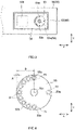
- FIG. 3 is a plan view schematically showing the structure in the vicinity of the electrode terminal on the negative electrode side of the sealed battery according to the present embodiment.
- FIG. 4 is a plan view showing an enlargement of a cap portion of a first member shown in FIG. 3 .
- FIG. 5 is an exploded perspective view of the electrode terminal of the sealed battery according to the present embodiment.
- a sealed battery 10 includes an electrode body 20, a case 30, and a pair of electrode terminals 40 and 50.
- an electrode body 20 As shown in FIG. 1 , a sealed battery 10 according to the present embodiment includes an electrode body 20, a case 30, and a pair of electrode terminals 40 and 50.
- each component will be described.
- the electrode body 20 is a power generation element housed inside the case 30.
- the electrode body 20 includes an elongated sheet-shaped positive electrode 21, an elongated sheet-shaped negative electrode 22, and elongated sheet-shaped separators 23 and 24.
- the electrode body 20 according to the present embodiment is a wound electrode body in which these elongated sheet-shaped members are wound in layers. It should be noted that the structure of the electrode body according to the technique disclosed herein is not limited to a wound electrode body and structures that can be adopted in a general sealed battery can be adopted without limitation.
- the electrode body may be a laminated electrode body in which a positive electrode and a negative electrode, each of which has a rectangular sheet shape, are laminated via a separator.
- the positive electrode 21 includes a positive electrode current collector 21a that is a foil-shaped conductive member and a positive electrode active material layer 21b applied to a surface (preferably, both surfaces) of the positive electrode current collector 21a.
- the positive electrode active material layer 21b is not formed but a positive electrode exposed portion 21c is formed in which the positive electrode current collector 21a is exposed.
- the negative electrode 22 includes a negative electrode current collector 22a that is a foil-shaped conductive member and a negative electrode active material layer 22b applied to a surface (preferably, both surfaces) of the negative electrode current collector 22a.
- the negative electrode active material layer 22b is not formed but a negative electrode exposed portion 22c is formed in which the negative electrode current collector 22a is exposed.
- the separators 23 and 24 are insulating sheets having a plurality of minute holes which a charge carrier (for example, lithium ions) can pass through. Each of the separators 23 and 24 is arranged between the positive electrode 21 and the negative electrode 22.
- materials which can be used in a conventional general secondary battery can be selected without any particular limitations as materials of the respective constituent members (the positive electrode 21, the negative electrode 22, and the separators 23 and 24) of the electrode body 20.
- materials of the constituent members of the electrode body 20 described above do not limit the technique disclosed herein, detailed descriptions of the materials will be omitted.
- a liquid electrolyte infiltrates the inside of the electrode body 20 (typically, between the positive electrode 21 and the negative electrode 22).
- the sealed battery 10 is configured so that a charge/discharge reaction occurs due to a movement of a charge carrier (for example, lithium ions) between the positive electrode 21 and the negative electrode 22 via the electrolyte solution.
- a form of the electrolyte is not limited to a liquid electrolyte and may alternatively be a gel-like polymer electrolyte or a solid electrolyte.
- materials that can be used in a conventional general secondary battery can be similarly used as components of the electrolyte solution without any particular limitations, and since the components of the electrolyte solution do not limit the technique disclosed herein, a detailed description thereof will be omitted.
- the case 30 is a container which houses the electrode body 20.
- the case 30 according to the present embodiment is a flat square container.
- the case 30 includes a square case body 32 of which an upper surface is opened and a plate-shaped lid 34 which closes an opening portion of the case body 32.
- the case 30 is sealed by joining the case body 32 and the lid 34 to each other by laser welding or the like.
- a terminal insertion hole 34a into which a connecting portion 52a of a first member 52 of an electrode terminal 50 is to be inserted is formed in the lid 34 according to the present embodiment (refer to FIGS. 2 and 5 ).
- a metal material such as aluminum, an aluminum alloy, or the like
- a metal material such as aluminum, an aluminum alloy, or the like
- the sealed battery 10 includes the pair of electrode terminals 40 and 50.
- the electrode terminals 40 and 50 are conductive members to act as a conductive path that connects the electrode body 20 inside the case 30 and an external conductive member (not illustrated) to each other.
- an "external conductive member” refers to a conductive member that connects an external device such as a vehicle or another battery and the sealed battery to each other.
- Examples of the external conductive member include a busbar that is a plate-shaped conductive member and a cable that is a linear conductive member.
- One of the pair of electrode terminals 40 and 50 is a positive electrode-side electrode terminal 40 (positive electrode terminal) to be connected to the positive electrode 21.
- the other is a negative electrode-side electrode terminal 50 (negative electrode terminal) to be connected to the negative electrode 22.
- the positive electrode terminal 40 and the negative electrode terminal 50 have approximately the same structure.
- a detailed structure of an electrode terminal will be described by focusing on the negative electrode terminal 50.
- the technique disclosed herein encompasses aspects including a positive electrode terminal of which a structure is approximately the same as that of the negative electrode terminal 50 to be described below.
- the electrode terminal 50 of the sealed battery 10 includes the first member 52 and a second member 54.
- an insulating member 60 is provided which prevents the electrode terminal 50 and the case 30 from becoming conductive.
- each of the first member 52, the second member 54, and the insulating member 60 will be described.
- the first member 52 is a conductive member which is connected to the electrode body 20 inside the case 30 and has the connecting portion 52a exposed to the outside of the case 30.
- the first member 52 according to the present embodiment is an elongated conductive member that extends along a height direction Z.
- a lower end 52b of the first member 52 is electrically connected to the electrode body 20 inside the case 30.
- the lower end 52b of the first member 52 on a negative electrode side is connected to the negative electrode exposed portion 22c of the electrode body 20.
- the connecting portion 52a which penetrates the case 30 (the lid 34) and the second member 54 and which is exposed to the outside of the case 30 is formed at an upper end of the first member 52.
- terminal insertion holes 34a, 60a, and 54a are respectively formed in the lid 34, the insulating member 60, and the second member 54 (refer to FIG. 5 ).
- the upper end of the connecting portion 52a is exposed to the outside of the case 30 by inserting the connecting portion 52a of the first member 52 into the terminal insertion holes 34a, 60a, and 54a.
- a cap portion 53 with a flat plate shape is formed at the upper end of the connecting portion 52a of the first member 52 which is exposed to the outside of the case 30.
- the cap portion 53 is molded by pressing and deforming (caulking) the upper end of the connecting portion 52a of the first member 52 toward the second member 54.
- forming the cap portion 53 by caulking causes the first member 52 and the second member 54 to be fixed to the lid 34 (the case 30) and connects the first member 52 and the second member 54 to each other.
- the cap portion 53 according to the present embodiment is molded so as to assume an approximately circular shape in a plan view.
- the second member 54 is a plate-shaped conductive member which is arranged outside of the case 30 and has a connection region 54b to be connected to an external conductive material.
- the second member 54 is connected to an external device such as a vehicle via an external conductive material such as a busbar.
- the second member 54 is a plate-shaped member that extends along a width direction X.
- the terminal insertion hole 54a into which the connecting portion 52a of the first member 52 is to be inserted is formed at one end of the second member 54 in the width direction X.
- the other end of the second member 54 in the width direction X is provided with the connection region 54b.
- connection region 54b is a flat region where holes, protrusions, and the like are not formed. Bringing the external conductive material into surface contact with the flat connection region 54b and joining the external conductive material with the connection region 54b enables the sealed battery 10 and an external device to be electrically connected to each other.
- the insulating member 60 is provided which prevents the electrode terminal 50 and the case 30 from becoming conductive.
- the insulating member 60 includes an insulated holder 62 and a gasket 64.
- the insulated holder 62 is a plate-shaped insulator that is arranged on the outside of the case 30 (an upper surface of the lid 34) and prevents the second member 54 and the lid 34 from becoming conductive.
- the gasket 64 is an approximately rectangular insulator that is arranged inside the case 30 (a lower surface of the lid 34) and prevents the first member 52 and the lid 34 from becoming conductive.
- the gasket 64 has a cylindrical protrusion 64a.
- the cylindrical protrusion 64a is inserted into the terminal insertion hole 34a of the lid 34 and pressure-bonded to a bottom surface of the insulated holder 62. Accordingly, the terminal insertion hole 60a of the insulating member 60 and the terminal insertion hole 34a of the lid 34 are arranged at a same position.
- the first member 52 and the second member 54 are connected to each other by localized ultrasonic joining.
- a plurality of (10 in the drawings) recessed portions 53a are formed on the upper surface of the cap portion 53 of the first member 52 in the present embodiment.
- the plurality of recessed portions 53a are dents which are formed when performing the localized ultrasonic joining described above.
- a bonding portion 55 due to an intermetallic bond is formed on a boundary between the first member 52 (the bottom surface of the cap portion 53) and the second member 54 below each recessed portion 53a (refer to FIG. 2 ).
- the bonding portion 55 due to an intermetallic bond has a lower resistance as compared to a welding mark created by laser welding or the like. Therefore, a contact resistance between the first member 52 and the second member 54 can be reduced and the electrode terminal 50 having superior conductivity can be constructed.
- FIG. 6 is a sectional view schematically showing a state prior to performing a step of caulking in the manufacturing method according to the present embodiment.
- FIG. 7 is a sectional view schematically showing a step of performing ultrasonic joining in the manufacturing method according to the present embodiment.
- the constituent members (the first member 52 and the second member 54) of the electrode terminal 50 and the constituent members (the insulated holder 62 and the gasket 64) of the insulating member 60 are prepared.
- the first member 52 prior to forming the electrode terminal 50 is provided with the cylindrical connecting portion 52a at an upper end in the height direction Z.
- the cap portion 53 such as that shown in FIGS. 2 to 4 is formed.
- the manufacturing method according to the present embodiment forms the electrode terminal 50 using the members described above by performing the steps of (1) assembly, (2) caulking, and (3) ultrasonic joining. Hereinafter, each step will be described.
- the second member 54 is arranged outside of the case 30 and the connecting portion 52a of the first member 52 is penetrated through each of the case 30 and the second member 54. Accordingly, as shown in FIG. 6 , constituent members of the electrode terminal can be assembled to the case 30 so that an upper end 52a2 of the connecting portion 52a of the first member 52 is exposed outside of the case 30.
- An example of specific procedures of the present step is as follows. First, the insulated holder 62 is arranged on the upper surface of the lid 34. At this point, an arrangement position of the insulated holder 62 is adjusted so that the terminal insertion hole 34a of the lid 34 and the terminal insertion hole 60a of the insulating holder 62 overlap with each other. Next, the protrusion 64a of the gasket 64 is inserted from a lower surface side of the lid 34 into the terminal insertion hole 34a of the lid 34. In addition, a region in a periphery of the terminal insertion hole 60a is pressed along the height direction Z.
- the bottom surface of the insulated holder 62 and the upper surface of the protrusion 64a of the gasket 64 are pressure-bonded to each other and the insulating member 62 is attached to the lid 34.
- the plate-shaped second member 54 is arranged on the insulated holder 62.
- an arrangement position of the second member 54 is adjusted so that the terminal insertion hole 54a of the second member 54 and the terminal insertion hole 60a of the insulating member 60 overlap with each other.
- the connecting portion 52a of the first member 52 is inserted into the terminal insertion holes 54a and 60a of the second member 54 and the insulating member 60 from a lower side of the lid 34 (inside of the case 30). Accordingly, the upper end 52a2 of the connecting portion 52a of the first member 52 is exposed on the outside of the case 30 (an upper side of the lid 34) (refer to FIG. 6 ).
- caulking is performed in which the upper end 52a2 of the connecting portion 52a of the first member 52 is pressed and deformed toward the second member 54. Accordingly, the cap portion 53 (refer to FIGS. 2 to 4 ) with a disk shape is formed in the connecting portion 52a of the first member 52 and the first member 52 and the second member 54 can be fixed to the case 30.
- an internal cavity 52a1 is formed in the cylindrical connecting portion 52a that is exposed to the outside of the case 30.
- a pressing member (not illustrated) is inserted into the internal cavity 52a1 of the connecting portion 52a and the upper end 52a2 of the connecting portion 52a is pressed and deformed so as to expand outward in a radial direction.
- the disk-shaped cap portion 53 (refer to FIG. 7 ) is formed at an upper end of the connecting portion 52a. Furthermore, in the present step, the formed cap portion 53 is pressed toward the second member 54.
- each of the connecting portion 52a of the first member 52, the second member 54, and the insulating member 60 deforms to close the terminal insertion holes 54a, 60a, and 34a and, at the same time, the first member 52 and the second member 54 are fixed to the case 30 (the lid 34).
- the cap portion 53 is pressed toward the second member 54 using a horn H having a plurality of protruded portions HI and, at the same time, ultrasonic waves are applied from each of the plurality of protruded portions H1.
- a plurality of recessed portions 53a are formed on the upper surface of the cap portion 53 and, at the same time, the bonding portion 55 (refer to FIG. 2 ) due to an intermetallic bond is formed on the boundary between the first member 52 and the second member 54 below each of the plurality of recessed portions 53a.
- An example of specific procedures of the present step is as follows. First, a region in which the second member 54, the insulated holder 62, and the lid 34 are laminated (for example, a vicinity of the connection region 54b) is sandwiched by a pair of fixing members F. Accordingly, since the second member 54 that is an object of joining is fixed, ultrasonic joining of the first member 52 and the second member 54 is made easier.
- the horn H having a plurality of (10) protruded portions HI is prepared, and ultrasonic waves are applied from each protruded portion HI of the horn H while pressing the protruded portions HI against the upper surface of the cap portion 53 and applying pressure toward the second member 54.
- an upper limit value of the pressure from the protruded portion HI is favorably 500 N or lower, more favorably 450 N or lower, even more favorably 400 N or lower, and particularly favorably 300 N or lower.
- a frequency of the ultrasonic waves applied from the protruded portion H1 is favorably 81 kHz or lower.
- an upper limit value of the frequency of the ultrasonic waves applied in ultrasonic joining is favorably 19 kHz or higher.
- a period of time (joining time) during which the ultrasonic waves are applied is favorably 0.03 seconds or longer, more favorably 0.1 seconds or longer, and particularly favorably 0.3 seconds or longer.
- the first member 52 and the second member 54 can be more preferably bonded to each other.
- an upper limit value of the joining time is favorably 3 seconds or shorter, more favorably 1 second or shorter, and particularly favorably 0.5 seconds or shorter.
- the bonding portion 55 due to an intermetallic bond is formed on the boundary between the first member 52 and the second member 54. Since the bonding portion 55 due to an intermetallic bond does not contain metal oxides, resistance is lower as compared to a welding mark created by hot welding using a laser or the like. Therefore, according to the present embodiment, the electrode terminal 50 in which a contact resistance between the first member 52 and the second member 54 is low and which has superior conductivity can be fabricated.
- spatter may scatter when welding the first member and the second member to each other and may adhere to members (for example, the lower surface of the lid and the lower end of the first member) which are arranged inside the case.
- members for example, the lower surface of the lid and the lower end of the first member
- conductive foreign objects can contaminate the inside of the battery and cause an internal short circuit.
- the manufacturing method according to the present embodiment also contributes toward suppressing an internal short circuit due to contamination by conductive foreign objects.
- a slight gap may be created between the cap portion of the first member and the second member after caulking.
- the first member and the second member are not sufficiently connected and conductivity of the electrode terminal declines significantly.
- the manufacturing method according to the present embodiment since ultrasonic joining is performed while pressing the cap portion of the first member toward the second member, even if a gap has been created between the cap portion of the first member and the second member after caulking, the first member and the second member can be connected so as to squash the gap. Therefore, according to the present embodiment, an occurrence of an electrode terminal with significantly declined conductivity can be reliably prevented.
- the number of locations where localized ultrasonic joining is performed is not particularly limited and can be changed as appropriate in consideration of dimensions of the cap portion 53 and the like.
- connection strength between the first member 52 and the second member 54 increases and, at the same time, a larger number of the low-resistance bonding portions 55 are to be formed.
- the number of recessed portions 53a formed in the cap portion 53 is favorably 3 or more, more favorably 4 or more, even more favorably 5 or more, and particularly favorably 6 or more.
- forming too many recessed portions 53a in the cap portion 53 may possibly cause strength of the cap portion 53 itself to decline.
- an upper limit of the number of recessed portions 53a is favorably 12 or less, more favorably 11 or less, and particularly favorably 10 or less.
- the horn H is provided with protruded portions HI that are approximately circular in a plan view so that approximately circular recessed portions 53a are formed in the cap portion 53 after being manufactured.
- the shape of the protruded portions H1 of the horn H is not particularly limited and a shape other than a circle (for example, a square) can also be adopted.
- the cap portion 53 can be evenly deformed centered on the protruded portions HI.
- the approximately circular protruded portions HI also has an effect of enabling ultrasonic waves from the protruded portions HI to be uniformly applied to the cap portion 53. Accordingly, as shown in FIG. 4 , the bonding portion 55 with an approximately circular shape centered on the recessed portion 53a is formed and the first member 52 and the second member 54 can be suitably connected to each other at low resistance.
- a radius of the recessed portion 53a is favorably 0.25 mm or longer, more favorably 0.3 mm or longer, even more favorably 0.5 mm or longer, and particularly favorably 0.75 mm or longer. Accordingly, the bonding portion 55 with a sufficient area can be formed below the recessed portion 53a. On the other hand, making the recessed portion 53a excessively large may possibly cause strength of the cap portion 53 itself to decline. From this perspective, an upper limit of the radius of the recessed portion 53a is favorably 1.5 mm or shorter, more favorably 1.3 mm or shorter, even more favorably 1.2 mm or shorter, and particularly favorably 1.0 mm or shorter.
- a pressing position in the radial direction is adjusted so that a gap S is created between an outer peripheral edge 53b and the recessed portion 53a of the cap portion 53 in the sealed battery after being manufactured.
- the bonding portion 55 due to an intermetallic bond is formed by plastically deforming the cap portion 53 while applying ultrasonic waves when performing ultrasonic joining.
- ultrasonic joining is favorably performed while pressing a position where the gap S is created between the outer peripheral edge 53b and the recessed portion 53a of the cap portion 53. Accordingly, the bonding portion 55 with a wide area can be secured and conductivity of the electrode terminal 50 can be further improved.
- a region that is close to the outer peripheral edge 53b than a center 53c of the cap portion 53 is favorably pressed.
- ultrasonic joining is favorably performed while pressing a position which is close to the outer peripheral edge 53b of the cap portion 53 but which avoids coming into contact with the outer peripheral edge 53b of the cap portion 53 (in other words, where the gap S is created). Accordingly, the bonding portion 55 with a sufficient area can be readily formed on the boundary between the first member 52 and the second member 54.
- the position of formation of the recessed portion 53a is favorably determined so as to satisfy Expression (1) below.
- an upper limit value of the distance A in Expression (1) above may be 0.2B or smaller, favorably 0.1B or smaller, more favorably smaller than 0.1B, even more favorably 0.05B or smaller, and particularly favorably smaller than 0.05B.
- a lower limit value of the distance A in Expression (1) above is favorably 0.01B or larger.
- the bonding portion 55 having a sufficient area can be readily formed as long as 60% or more (preferably 70% or more and more preferably 80% or more) of the recessed portions 53a are formed at positions satisfying Expression (1).
- a major portion (in FIG. 3 , 9 out of 10) of the plurality of recessed portions 53a are formed in a region that opposes the connection region 54b of the second member 54.
- a position of formation of the recessed portions 53a in the circumferential direction is not particularly limited and, as shown in FIG. 8 , all of the recessed portions 53a may be equally formed in the circumferential direction. It should be noted that, as shown in FIG. 3 , when a major portion of the recessed portions 53a are formed in a region that opposes the connection region 54b of the second member 54, a conductive path from the first member 52 to an external conductive material (the connection region 54b) becomes shorter.
- the number of recessed portions 53a formed at positions opposing the connection region 54b is favorably 60% or more of a total number of the recessed portions 53a, more favorably 70% or more of the total number of the recessed portions 53a, and particularly favorably 80% or more of the total number of the recessed portions 53a. Accordingly, the electrode terminal 50 with more superior conductivity can be fabricated.
- a part of the plurality of recessed portions 53a are favorably formed in a region on an opposite side to the connection region 54b. From this perspective, the number of recessed portions 53a formed at positions opposing the connection region 54b is favorably 95% or less of the total number of the recessed portions 53a and more favorably 90% or less of the total number of the recessed portions 53a.
- the first member 52 including the cylindrical connecting portion 52a is used to press and deform the cylindrical connecting portion 52a in the step of caulking to form the disk-shaped cap portion 53.
- shapes of the connecting portion 52a prior to being manufactured and the cap portion 53 after being manufactured are not limited to the embodiment described above and various shapes can be adopted without particular limitation.
- the quadrangular prism-shaped connecting portion may be pressed and deformed in the step of caulking.
- the cap portion with an approximately rectangular shape in a plan view is to be formed at an upper end of the connecting portion of the first member.
- the first member and the second member can be suitably fixed to each other.
- the electrode terminal 50 constituted by only the first member 52 and the second member 54 is used.
- the constituent members of the electrode terminal are not limited to only the first member and the second member, and even when fabricating an electrode terminal constituted by three or more components, the technique disclosed herein can be applied.
- the first member 52 and the electrode body 20 are directly connected to each other (refer to FIG. 2 ).
- another conductive member (a third member) may be arranged between the first member and the electrode body and the first member and the electrode body may be connected to each other via the third member. Even when using such a third member, the technique disclosed herein can be applied as long as the cap portion is formed by exposing the upper end of the first member to the outside of the case.
- the second member 54 has the flat connection region 54b.
- the connection region 54b of the second member 54 is not particularly limited as long as an external connecting member can be connected.
- a second member configured such that a connection region is provided with a bolt and the external connecting member is fixed by tightening a nut or the like to the bolt can also be used.
- the connection region of the second member may be provided with a structure into which a cable-like external connecting member is inserted to be fixed to the connection region of the second member.
- Materials of the respective members that constitute the electrode terminal are not particularly limited and materials that can be used in an electrode terminal of a sealed battery can be used without any particular limitations.
- a metal member with superior strength and conductivity such as aluminum, copper, nickel, iron, and alloys thereof can be used.
- the technique disclosed herein can be particularly preferably applied to an electrode terminal in which raw materials of the first member and the second member differ from each other. For example, when the terminal connection location (for example, the negative electrode exposed portion 22c in FIG.
- the first member 52 is made of a same raw material as the terminal connection location of the electrode body 20 and the second member 54 is made of a same raw material as the external connecting member.
- the first member 52 and the second member 54 are metal members of different types.
- the first member 52 and the second member 54 are connected to each other by localized ultrasonic joining as in the technique disclosed herein, even when the first member 52 and the second member 54 are metal members of different types, the first member 52 and the second member 54 can be strongly connected to each other without causing an increase in resistance.
- the technique disclosed herein can exhibit a particularly preferable effect when the first member 52 and the second member 54 are dissimilar metals.
Landscapes
- Chemical & Material Sciences (AREA)
- Chemical Kinetics & Catalysis (AREA)
- Electrochemistry (AREA)
- General Chemical & Material Sciences (AREA)
- Engineering & Computer Science (AREA)
- Manufacturing & Machinery (AREA)
- Materials Engineering (AREA)
- Mechanical Engineering (AREA)
- Connection Of Batteries Or Terminals (AREA)
- Sealing Battery Cases Or Jackets (AREA)
Applications Claiming Priority (1)
| Application Number | Priority Date | Filing Date | Title |
|---|---|---|---|
| JP2020205527A JP7285817B2 (ja) | 2020-12-11 | 2020-12-11 | 密閉型電池および密閉型電池の製造方法 |
Publications (1)
| Publication Number | Publication Date |
|---|---|
| EP4012833A1 true EP4012833A1 (en) | 2022-06-15 |
Family
ID=78822595
Family Applications (1)
| Application Number | Title | Priority Date | Filing Date |
|---|---|---|---|
| EP21212611.4A Pending EP4012833A1 (en) | 2020-12-11 | 2021-12-06 | Sealed battery and method of manufacturing sealed battery |
Country Status (4)
| Country | Link |
|---|---|
| US (1) | US20220190448A1 (ja) |
| EP (1) | EP4012833A1 (ja) |
| JP (1) | JP7285817B2 (ja) |
| CN (1) | CN114628865A (ja) |
Citations (4)
| Publication number | Priority date | Publication date | Assignee | Title |
|---|---|---|---|---|
| JP2013161629A (ja) * | 2012-02-03 | 2013-08-19 | Toyota Motor Corp | 二次電池の製造方法、及びそれによって製造される二次電池 |
| JP5590391B2 (ja) | 2010-07-27 | 2014-09-17 | 日立オートモティブシステムズ株式会社 | 二次電池 |
| US20160372722A1 (en) * | 2015-06-22 | 2016-12-22 | Sanyo Electric Co., Ltd. | Secondary battery and battery pack using the same |
| US20190273240A1 (en) * | 2018-03-02 | 2019-09-05 | Toyota Jidosha Kabushiki Kaisha | Battery and method of manufacturing battery |
Family Cites Families (8)
| Publication number | Priority date | Publication date | Assignee | Title |
|---|---|---|---|---|
| JP4797219B2 (ja) * | 1999-12-09 | 2011-10-19 | パナソニック株式会社 | 電池のリード線接続装置 |
| JP2014010992A (ja) * | 2012-06-28 | 2014-01-20 | Toyota Motor Corp | 密閉型電池及びその製造方法 |
| JP6282794B2 (ja) * | 2012-07-30 | 2018-02-21 | 株式会社Gsユアサ | 蓄電素子及びその製造方法 |
| CN105849939B (zh) * | 2013-08-22 | 2018-09-07 | 日立汽车系统株式会社 | 二次电池 |
| JP6731289B2 (ja) * | 2016-06-22 | 2020-07-29 | プライムアースEvエナジー株式会社 | 電池の製造方法及び電池 |
| JP2019009045A (ja) * | 2017-06-27 | 2019-01-17 | 株式会社Gsユアサ | 蓄電素子 |
| JP2020166969A (ja) * | 2019-03-28 | 2020-10-08 | 株式会社Gsユアサ | 蓄電素子及びその製造方法 |
| JP7194335B2 (ja) * | 2019-04-23 | 2022-12-22 | トヨタ自動車株式会社 | 二次電池の製造方法および二次電池 |
-
2020
- 2020-12-11 JP JP2020205527A patent/JP7285817B2/ja active Active
-
2021
- 2021-12-06 EP EP21212611.4A patent/EP4012833A1/en active Pending
- 2021-12-07 US US17/544,874 patent/US20220190448A1/en active Pending
- 2021-12-10 CN CN202111502943.0A patent/CN114628865A/zh active Pending
Patent Citations (4)
| Publication number | Priority date | Publication date | Assignee | Title |
|---|---|---|---|---|
| JP5590391B2 (ja) | 2010-07-27 | 2014-09-17 | 日立オートモティブシステムズ株式会社 | 二次電池 |
| JP2013161629A (ja) * | 2012-02-03 | 2013-08-19 | Toyota Motor Corp | 二次電池の製造方法、及びそれによって製造される二次電池 |
| US20160372722A1 (en) * | 2015-06-22 | 2016-12-22 | Sanyo Electric Co., Ltd. | Secondary battery and battery pack using the same |
| US20190273240A1 (en) * | 2018-03-02 | 2019-09-05 | Toyota Jidosha Kabushiki Kaisha | Battery and method of manufacturing battery |
Also Published As
| Publication number | Publication date |
|---|---|
| US20220190448A1 (en) | 2022-06-16 |
| JP7285817B2 (ja) | 2023-06-02 |
| JP2022092680A (ja) | 2022-06-23 |
| CN114628865A (zh) | 2022-06-14 |
Similar Documents
| Publication | Publication Date | Title |
|---|---|---|
| US10079370B2 (en) | Secondary battery | |
| JP5856858B2 (ja) | 角形二次電池の製造方法 | |
| US10062873B2 (en) | Secondary battery and battery pack using the same | |
| JP6582443B2 (ja) | 二次電池及びその製造方法 | |
| JP2003346770A (ja) | 電 池 | |
| EP4012833A1 (en) | Sealed battery and method of manufacturing sealed battery | |
| EP4037090B1 (en) | Electrode terminal and secondary battery provided with said electrode terminal | |
| WO2019131356A1 (ja) | 蓄電装置 | |
| JP7402202B2 (ja) | 端子部品および端子部品の製造方法 | |
| JPWO2018235768A1 (ja) | 蓄電素子 | |
| EP3972043B1 (en) | Terminal for secondary battery and secondary battery provided with the terminal | |
| US20220231388A1 (en) | Terminal component, secondary battery, and battery pack | |
| JP7389766B2 (ja) | 端子部品、それを備えた二次電池および組電池並びに端子部品の製造方法 | |
| JP7334215B2 (ja) | ホーン、端子部品および二次電池 | |
| JPWO2019116914A1 (ja) | 蓄電素子 | |
| JP2024037388A (ja) | 電池、および電池の製造方法 | |
| CN114843670A (zh) | 电极端子及其利用 | |
| CN112599938A (zh) | 密闭型电池 |
Legal Events
| Date | Code | Title | Description |
|---|---|---|---|
| PUAI | Public reference made under article 153(3) epc to a published international application that has entered the european phase |
Free format text: ORIGINAL CODE: 0009012 |
|
| STAA | Information on the status of an ep patent application or granted ep patent |
Free format text: STATUS: REQUEST FOR EXAMINATION WAS MADE |
|
| 17P | Request for examination filed |
Effective date: 20211206 |
|
| AK | Designated contracting states |
Kind code of ref document: A1 Designated state(s): AL AT BE BG CH CY CZ DE DK EE ES FI FR GB GR HR HU IE IS IT LI LT LU LV MC MK MT NL NO PL PT RO RS SE SI SK SM TR |
|
| RAP3 | Party data changed (applicant data changed or rights of an application transferred) |
Owner name: PRIME PLANET ENERGY & SOLUTIONS, INC. |