EP4012101A1 - Heckfräse für eine pistenraupe zur schneeflächenbearbeitung - Google Patents
Heckfräse für eine pistenraupe zur schneeflächenbearbeitung Download PDFInfo
- Publication number
- EP4012101A1 EP4012101A1 EP21209765.3A EP21209765A EP4012101A1 EP 4012101 A1 EP4012101 A1 EP 4012101A1 EP 21209765 A EP21209765 A EP 21209765A EP 4012101 A1 EP4012101 A1 EP 4012101A1
- Authority
- EP
- European Patent Office
- Prior art keywords
- tiller
- shaft
- milling
- drive
- shaft parts
- Prior art date
- Legal status (The legal status is an assumption and is not a legal conclusion. Google has not performed a legal analysis and makes no representation as to the accuracy of the status listed.)
- Granted
Links
Images


Classifications
-
- E—FIXED CONSTRUCTIONS
- E01—CONSTRUCTION OF ROADS, RAILWAYS, OR BRIDGES
- E01H—STREET CLEANING; CLEANING OF PERMANENT WAYS; CLEANING BEACHES; DISPERSING OR PREVENTING FOG IN GENERAL CLEANING STREET OR RAILWAY FURNITURE OR TUNNEL WALLS
- E01H4/00—Working on surfaces of snow or ice in order to make them suitable for traffic or sporting purposes, e.g. by compacting snow
- E01H4/02—Working on surfaces of snow or ice in order to make them suitable for traffic or sporting purposes, e.g. by compacting snow for sporting purposes, e.g. preparation of ski trails; Construction of artificial surfacings for snow or ice sports ; Trails specially adapted for on-the-snow vehicles, e.g. devices adapted for ski-trails
Definitions
- the invention relates to a rear tiller for a snow groomer for working snow surfaces, with a support structure which is designed for detachable attachment to a rear implement carrier of the snow groomer and which carries a tiller box in which a tiller shaft arrangement is rotatably mounted, which has at least two tiller shaft parts that are driven by a drive system are drivable.
- Such a tail cutter is from the DE 10 2006 057 272 B4 known.
- the well-known rear tiller has a support structure on which a multi-part tiller box is held.
- a milling shaft arrangement is rotatably mounted in the milling box, with each milling box part being assigned a milling shaft part.
- a finisher arrangement is provided, which compacts and smoothes snow grain sizes that have been chopped up by the tiller shaft arrangement.
- the object of the invention is to create a rear tiller of the type mentioned at the outset that has a reduced weight compared to the prior art and an improved distribution of installation space.
- the auger shaft parts are coupled to one another in a rotationally locked manner by means of a coupling device arranged between the adjacent auger shaft parts, and that the drive system has a belt drive acting in the area of the coupling device, which is connected to both auger shaft parts in a torque-transmitting manner.
- the solution according to the invention avoids drive motors arranged at the ends of the milling box. In this way, at the end, ie at the opposite end faces of the milling box, space is achieved for an arrangement of a side finisher unit in each case.
- the belt drive acting in the middle between two milling shaft parts ensures that the milling shaft parts are driven without the corresponding drive motors being arranged on the end of the milling box.
- a corresponding drive motor can be fastened at a distance above the milling shaft arrangement on the milling box or on a section of the support structure.
- the solution according to the invention also makes it possible to drive at least two milling shaft parts by means of the belt drive and thus by means of a single drive motor. According to the invention, increased running smoothness also results. Due to the reduced number of components for the drive system, the production costs for the rear tiller according to the invention are also reduced.
- the coupling device is designed as a cardan shaft allowing an angular offset between the axes of rotation of the two milling shaft parts. On the one hand, this ensures reliable torque transmission between the two milling shaft parts. On the other hand, angle compensation is possible between the axes of rotation of the two milling shaft parts, so that the two milling shaft parts do not have to be coaxially aligned with one another, but can also be twisted relative to one another at limited angles.
- the belt drive has a driven gear which is connected to the auger shaft part coaxially to an axis of rotation of a auger shaft part and is designed as a ring gear, and the articulated shaft passes through the ring gear.
- the ring gear which serves as the output gear, is passed through by the cardan shaft without contact.
- a free inner diameter of the ring gear is dimensioned so large that angular alignments of the articulated shaft within the ring gear are also possible without the articulated shaft making contact with an interior of the ring gear.
- the ring gear is arranged to be axially displaceable relative to the cardan shaft. This configuration enables simple assembly and disassembly of corresponding functional components of the rear tiller, in particular the tiller shaft parts, the belt drive and the cardan shaft.
- the auger shaft part is provided on a front side facing the adjacent auger shaft part with a drive flange designed as a hollow body, which encloses the cardan shaft on the outside and is non-rotatably connected to the ring gear at an end region spaced apart from the auger shaft part.
- the hollow body is preferably designed like a bell and on the one hand allows attachment to the ring gear of the belt drive and on the other hand a non-contact enclosing of the cardan shaft.
- the hollow body is fastened on the face side to the assigned milling shaft part.
- the connecting flange designed as a hollow body is also designed in such a way that it can at least partially dip axially into an open front end area of the auger shaft part, so that the axial overall length of the auger shaft part is almost not increased despite the attachment of the connecting flange.
- the two milling shaft parts can be aligned at a limited angle relative to one another.
- This configuration is advantageous when the rear cutter is in operation, since a straight-line stability of the rear cutter when towing on the snow groomer can be improved by correspondingly V- or W-shaped alignment of the various cutter shaft parts of the rear cutter.
- the V-shaped or W-shaped alignment is preferably in a plane that is aligned parallel to a snow base to be processed.
- the angular one Alignment of the tiller shaft parts is advantageously carried out mirror-symmetrically to a central axis extending in the towing direction of the rear tiller or to a vertical central plane receiving the central axis.
- a drive motor of the drive system is mounted at a distance above the ring gear on the support structure or the milling box, and the drive motor is coupled to a drive wheel of the belt drive.
- the drive motor is preferably hydraulic or electric.
- One drive motor is advantageously provided for each two adjacent milling shaft parts. Accordingly, if the auger shaft arrangement has four auger shaft parts, two drive motors and two belt drives are advantageously provided.
- the milling box is made in several parts, so that for each milling shaft part there is an impact housing part surrounding the milling shaft part at a distance. The baffle housing parts are held to the support structure.
- the belt drive is designed as a toothed belt drive. This results in low-loss torque transmission from the drive motor to the milling shaft parts.
- a rear tiller 1 after the Figures 1 to 6 is intended for a tracked vehicle in the form of a snow groomer.
- the rear tiller 1 is used for processing snow surfaces in winter sports areas.
- the rear tiller is detachably attached to the rear of the snow groomer.
- the snow groomer has, in a manner known in principle, a rear implement carrier to which the rear tiller 1 is connected.
- the rear tiller 1 is provided with a centrally arranged holding device 5 which is firmly connected to a support structure 2 of the rear tiller 1 .
- the holding device 5 has, as shown in FIG 3 can be seen, a hook 8 on which the rear tiller 1 is attached to the rear implement carrier, not shown, of the snow groomer.
- the support structure 2 carries a milling box 3 which is provided for receiving a milling shaft arrangement 4 .
- the milling box 3 is designed in several parts and, in the exemplary embodiment shown, has two milling housing parts, in each of which a milling shaft part of the milling shaft arrangement 4 is rotatably mounted.
- the rear tiller 1 has a finisher arrangement F behind the tiller shaft arrangement 4 in the towing direction.
- side finishers S are assigned to the milling box 3 on opposite front sides, which in 1 are not shown.
- the two milling housing parts of the milling box 3, which enclose the two milling shaft parts 4, are held at a small axial distance from one another transversely to the towing direction of the rear tiller 1.
- One milling housing part can be angularly aligned to a limited extent relative to the adjacent milling housing part of the milling box 3, such as figure 5 can be removed.
- the two milling shaft parts 4, which are rotatably mounted in the respective milling housing part, are spaced apart axially from one another, analogously to the impact housing parts, transversely to the towing direction.
- the milling shaft parts 4 are aligned coaxially to one another with aligned axes of rotation D 1 and D 2 and are coupled to one another in a torque-transmitting manner via a coupling device 7 described in more detail below.
- the torque-transmitting coupling of the two milling shaft parts 4 relative to one another takes place via an articulated shaft 12, which permits angular alignments of the milling shaft parts 4 relative to one another and nevertheless ensures reliable torque transmission.
- the in the 1 and 2 and 5, 6 right milling shaft part 4 is driven by a drive system which has a drive motor 6 and a belt drive 9 to 11.
- the belt drive 9 to 11 is provided with a driven wheel in the form of a ring gear 10 and with a drive wheel 9 which is held in a rotationally fixed manner on a drive shaft of the drive motor 6 (not designated in any more detail).
- the drive wheel 9 and the ring gear 10 are one circulating toothed belt 11 connected to each other.
- the ring gear 10 is connected to a front end area 13 of the right-hand milling shaft part 4 via a drive flange 16 designed as a hollow body.
- the front end area 13 is held rotatably by means of a roller bearing 14 on a bearing flange 15 which is firmly connected to the milling housing part of the milling box 3 .
- the cardan shaft 12 has two shaft flange sections, not designated in any more detail, which are connected to one another by means of a central joint section.
- the two shaft flanges are non-rotatably connected to the opposite end regions 13 of the two milling shaft parts 4 .
- the cardan shaft 12 is mounted inside the drive flange 16, which is designed as a bell-shaped hollow body, and inside the ring gear 10, so that the cardan shaft 12 can drive the ring gear 10 coaxially to the axes of rotation D 1 and D 2 of the Milling shaft parts 4 interspersed.
- the ring gear 10 which is connected with screw connections to the drive flange 16 designed as a hollow body, can be detached from the drive flange 16 and moved axially towards the adjacent milling shaft part 4 , like this in 6 is recognizable. In this position, access to the articulated shaft 12 and to the attachment to the end regions 13 of the auger shaft parts 14 is enabled, so that the coupling device 7 can be assembled or disassembled without having to remove the auger housing parts or the auger shaft parts 4 .
Landscapes
- Engineering & Computer Science (AREA)
- Architecture (AREA)
- Civil Engineering (AREA)
- Structural Engineering (AREA)
- Soil Working Implements (AREA)
Abstract
Description
- Die Erfindung betrifft eine Heckfräse für eine Pistenraupe zur Schneeflächenbearbeitung mit einer Trägerstruktur, die zur lösbaren Befestigung an einem Heckgeräteträger der Pistenraupe ausgebildet ist, und die einen Fräskasten trägt, in dem eine Fräswellenanordnung drehbar gelagert ist, die wenigstens zwei Fräswellenteile aufweist, die durch ein Antriebssystem antreibbar sind.
- Eine derartige Heckfräse ist aus der
DE 10 2006 057 272 B4 bekannt. Die bekannte Heckfräse weist eine Trägerstruktur auf, an der ein mehrteiliger Fräskasten gehalten ist. In dem Fräskasten ist eine Fräswellenanordnung drehbar gelagert, wobei jedem Fräskastenteil jeweils ein Fräswellenteil zugeordnet ist. Im Schleppbetrieb der Heckfräse hinter dem Fräskasten ist eine Finisheranordnung vorgesehen, die durch die Fräswellenanordnung zerkleinerte Schneekorngrößen verdichtet und glättet. - Aufgabe der Erfindung ist es, eine Heckfräse der eingangs genannten Art zu schaffen, die ein gegenüber dem Stand der Technik reduziertes Gewicht sowie eine verbesserte Bauraumverteilung aufweist.
- Diese Aufgabe wird dadurch gelöst, dass die Fräswellenteile mittels einer zwischen den benachbarten Fräswellenteilen angeordneten Koppeleinrichtung drehschlüssig miteinander gekoppelt sind, und dass das Antriebssystem einen im Bereich der Koppeleinrichtung angreifenden Riementrieb aufweist, der drehmomentübertragend mit beiden Fräswellenteilen verbunden ist. Durch die erfindungsgemäße Lösung werden endseitig an dem Fräskasten angeordnete Antriebsmotoren vermieden. Damit wird endseitig, d.h. an den gegenüberliegenden Stirnseiten des Fräskastens, Bauraum für eine Anordnung jeweils einer Seitenfinishereinheit erzielt. Der mittig zwischen jeweils zwei Fräswellenteilen angreifende Riementrieb gewährleistet einen Antrieb der Fräswellenteile ohne eine endseitige Anordnung entsprechender Antriebsmotoren am Fräskasten. Ein entsprechender Antriebsmotor kann vielmehr in Abstand oberhalb der Fräswellenanordnung am Fräskasten oder einem Abschnitt der Trägerstruktur befestigt sein. Durch die erfindungsgemäße Lösung ist es zudem möglich, jeweils wenigstens zwei Fräswellenteile mittels des Riementriebs und damit mittels eines einzelnen Antriebsmotors anzutreiben. Erfindungsgemäß ergibt sich zudem eine erhöhte Laufruhe. Aufgrund der reduzierten Anzahl von Bauteilen für das Antriebssystem reduzieren sich zwangsläufig auch Herstellkosten für die erfindungsgemäße Heckfräse.
- In Ausgestaltung der Erfindung ist die Koppeleinrichtung als einen Winkelversatz zwischen Drehachsen der beiden Fräswellenteile zulassende Gelenkwelle gestaltet. Dadurch ist zum einen eine sichere Drehmomentübertragung zwischen den beiden Fräswellenteilen gewährleistet. Zum anderen ist zwischen den Drehachsen der beiden Fräswellenteile ein Winkelausgleich möglich, so dass die beiden Fräswellenteile nicht zueinander koaxial fluchten müssen, sondern auch in begrenzten Winkeln relativ zueinander verschränkt sein können.
- In weiterer Ausgestaltung der Erfindung weist der Riementrieb ein koaxial zu einer Drehachse eines Fräswellenteils mit dem Fräswellenteil verbundenes Abtriebsrad auf, das als Hohlrad ausgeführt ist, und die Gelenkwelle durchsetzt das Hohlrad. Das als Abtriebsrad dienende Hohlrad wird von der Gelenkwelle berührungslos durchsetzt. Ein freier Innendurchmesser des Hohlrads ist so groß bemessen, dass auch winklige Ausrichtungen der Gelenkwelle innerhalb des Hohlrads möglich sind, ohne dass die Gelenkwelle ein Inneres des Hohlrads kontaktiert.
- In weiterer Ausgestaltung der Erfindung ist das Hohlrad relativ zu der Gelenkwelle axial verschiebbar angeordnet. Diese Ausgestaltung ermöglicht eine einfache Montage und Demontage entsprechender Funktionskomponenten der Heckfräse, insbesondere der Fräswellenteile, des Riementriebs und der Gelenkwelle.
- In weiterer Ausgestaltung der Erfindung ist der Fräswellenteil auf einer dem benachbarten Fräswellenteil zugewandten Stirnseite mit einem als Hohlkörper ausgeführten Antriebsflansch versehen, der die Gelenkwelle außenseitig umschließt und an einem zu dem Fräswellenteil beabstandeten Stirnendbereich mit dem Hohlrad drehschlüssig verbunden ist. Der Hohlkörper ist vorzugsweise glockenartig gestaltet und ermöglicht zum einen die Befestigung an dem Hohlrad des Riementriebs und zum anderen ein berührungsloses Umschließen der Gelenkwelle. Der Hohlkörper ist schließlich stirnseitig an dem zugeordneten Fräswellenteil befestigt. Der als Hohlkörper ausgeführte Verbindungsflansch ist zudem derart gestaltet, dass er zumindest teilweise axial in einen offenen Stirnendbereich des Fräswellenteils eintauchen kann, so dass eine axiale Baulänge des Fräswellenteils trotz der Befestigung des Verbindungsflansches nahezu nicht vergrößert ist.
- In weiterer Ausgestaltung der Erfindung sind die beiden Fräswellenteile relativ zueinander begrenzt winklig ausrichtbar. Diese Ausgestaltung ist im Betrieb der Heckfräse vorteilhaft, da durch entsprechend V- oder W-förmige Ausrichtung der verschiedenen Fräswellenteile der Heckfräse ein Geradeauslauf der Heckfräse im Schleppbetrieb an der Pistenraupe verbessert werden kann. Die V- oder W-förmige Ausrichtung erfolgt vorzugsweise in einer Ebene, die parallel zu einem zu bearbeitenden Schneeuntergrund ausgerichtet ist. Die winklige Ausrichtung der Fräswellenteile erfolgt vorteilhaft spiegelsymmetrisch zu einer in Schlepprichtung der Heckfräse erstreckten Mittelachse oder einer die Mittelachse aufnehmenden, vertikalen Mittelebene.
- In weiterer Ausgestaltung der Erfindung ist ein Antriebsmotor des Antriebssystems in Abstand oberhalb des Hohlrads an der Trägerstruktur oder dem Fräskasten montiert, und der Antriebsmotor ist mit einem Antriebsrad des Riementriebs gekoppelt. Der Antriebsmotor ist vorzugsweise hydraulisch oder elektrisch ausgeführt. Vorteilhaft ist jeweils ein Antriebsmotor für jeweils zwei benachbarte Fräswellenteile vorgesehen. Falls demzufolge die Fräswellenanordnung vier Fräswellenteile aufweist, sind vorteilhaft zwei Antriebsmotoren und zwei Riementriebe vorgesehen. Der Fräskasten ist je nach Anzahl der Fräswellenteile mehrteilig ausgeführt, so dass für jeweils einen Fräswellenteil jeweils ein den Fräswellenteil in Abstand umgebendes Prallgehäuseteil vorgesehen ist. Die Prallgehäuseteile sind an der Trägerstruktur gehalten.
- In weiterer Ausgestaltung der Erfindung ist der Riementrieb als Zahnriementrieb ausgeführt. Hierdurch ergibt sich eine verlustarme Drehmomentübertragung des Antriebsmotors auf die Fräswellenteile.
- Weitere Vorteile und Merkmale der Erfindung ergeben sich aus den Ansprüchen sowie aus der nachfolgenden Beschreibung eines bevorzugten Ausführungsbeispiels der Erfindung, das anhand der Zeichnungen dargestellt ist.
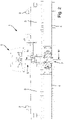
- Fig. 1
- zeigt in einem quer zur Schlepprichtung ausgerichteten Längsschnitt eine Ausführungsform einer erfindungsgemäßen Heckfräse,
- Fig. 2
- einen Teilbereich der Heckfräse gemäß
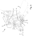
Fig. 1 in vergrößerter Darstellung, - Fig. 3
- einen Querschnitt durch die Heckfräse gemäß den
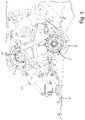
Fig. 1 und2 entlang der Schnittlinie III-III inFig. 2 , - Fig. 4
- die Darstellung gemäß
Fig. 3 , jedoch als vergrößerter Teilbereich, - Fig. 5
- in vergrößerter Schnittdarstellung eine Koppeleinrichtung für zwei benachbarte Fräswellenteile der Heckfräse nach den
Fig. 1 bis 4 und - Fig. 6
- die Koppeleinrichtung gemäß
Fig. 5 , jedoch in einer Montagestellung. - Eine Heckfräse 1 nach den
Fig. 1 bis 6 ist für ein Kettenfahrzeug in Form einer Pistenraupe vorgesehen. Die Heckfräse 1 dient zur Bearbeitung von Schneeoberflächen in Wintersportgebieten. Die Heckfräse wird heckseitig lösbar an die Pistenraupe angebaut. Hierzu weist die Pistenraupe in grundsätzlich bekannter Weise einen Heckgeräteträger auf, mit dem die Heckfräse 1 verbunden wird. - Die Heckfräse 1 ist mit einer mittig angeordneten Haltevorrichtung 5 versehen, die mit einer Trägerstruktur 2 der Heckfräse 1 fest verbunden ist. Die Haltevorrichtung 5 weist, wie anhand der
Fig. 3 erkennbar ist, einen Aufnahmehaken 8 auf, über den die Heckfräse 1 an dem nicht dargestellten Heckgeräteträger der Pistenraupe befestigt wird. Die Trägerstruktur 2 trägt einen Fräskasten 3, der zur Aufnahme einer Fräswellenanordnung 4 vorgesehen ist. Dabei ist der Fräskasten 3 mehrteilig gestaltet und weist beim dargestellten Ausführungsbeispiel zwei Fräsgehäuseteile auf, in dem jeweils ein Fräswellenteil der Fräswellenanordnung 4 drehbar gelagert ist. - Die Heckfräse 1 weist in Schlepprichtung hinter der Fräswellenanordnung 4 eine Finisheranordnung F auf. Zudem sind dem Fräskasten 3 an gegenüberliegenden Stirnseiten Seitenfinisher S zugeordnet, die in
Fig. 1 nicht dargestellt sind. - Wie anhand der
Fig. 2 und5, 6 gut erkennbar ist, sind die beiden Fräsgehäuseteile des Fräskastens 3, die die beiden Fräswellenteile 4 umschließen, mit geringem axialen Abstand quer zur Schlepprichtung der Heckfräse 1 zueinander gehalten. Der eine Fräsgehäuseteil ist gegenüber dem benachbarten Fräsgehäuseteil des Fräskastens 3 begrenzt winklig ausrichtbar, wieFig. 5 entnommen werden kann. Die beiden in dem jeweiligen Fräsgehäuseteil drehbar gelagerten Fräswellenteile 4 sind analog der Prallgehäuseteile quer zur Schlepprichtung axial zueinander beabstandet. Die Fräswellenteile 4 sind bei fluchtenden Drehachsen D1 und D2 koaxial zueinander ausgerichtet und über eine nachfolgend näher beschriebene Koppeleinrichtung 7 miteinander drehmomentübertragend gekoppelt. Die drehmomentübertragende Kopplung der beiden Fräswellenteile 4 relativ zueinander erfolgt über eine Gelenkwelle 12, die winklige Ausrichtungen der Fräswellenteile 4 relativ zueinander zulässt und dennoch eine sichere Drehmomentübertragung gewährleistet. - Der in den
Fig. 1 und2 sowie 5, 6 rechte Fräswellenteil 4 wird durch ein Antriebssystem angetrieben, das einen Antriebsmotor 6 sowie einen Riementrieb 9 bis 11 aufweist. Der Riementrieb 9 bis 11 ist mit einem Abtriebsrad in Form eines Hohlrads 10 sowie mit einem Antriebsrad 9 versehen, das drehfest auf einer nicht näher bezeichneten Antriebswelle des Antriebsmotors 6 gehalten ist. Das Antriebsrad 9 und das Hohlrad 10 sind über einen umlaufenden Zahnriemen 11 miteinander verbunden. Das Hohlrad 10 ist über einen als Hohlkörper ausgeführten Antriebsflansch 16 mit einem Stirnendbereich 13 des rechten Fräswellenteils 4 verbunden. Der Stirnendbereich 13 ist mithilfe einer Wälzlagerung 14 an einem Lagerflansch 15 drehbar gehalten, der fest mit dem Fräsgehäuseteil des Fräskastens 3 verbunden ist. - Die Gelenkwelle 12 weist zwei nicht näher bezeichnete Wellenflanschabschnitte auf, die mittels eines mittigen Gelenkabschnitts miteinander verbunden sind. Die beiden Wellenflansche sind mit den gegenüberliegenden Stirnendbereichen 13 der beiden Fräswellenteile 4 drehfest verbunden. Wie anhand der
Fig. 5 und 6 gut erkennbar ist, ist die Gelenkwelle 12 innerhalb des als glockenförmiger Hohlkörper gestalteten Antriebsflansches 16 und innerhalb des Hohlrads 10 montiert, so dass die Gelenkwelle 12 das Hohlrad 10 im betriebsfertig montierten Zustand an dem Antriebsflansch 16 berührungsfrei koaxial zu den Drehachsen D1 und D2 der Fräswellenteile 4 durchsetzt. - Für eine Montage oder Demontage der verschiedenen, zuvor beschriebenen Funktionskomponenten der Koppeleinrichtung 7 kann in einfacher Weise das Hohlrad 10, das mit Schraubverbindungen mit dem als Hohlkörper gestalteten Antriebsflansch 16 verbunden ist, von dem Antriebsflansch 16 gelöst und axial zu dem benachbarten Fräswellenteil 4 hin verschoben werden, wie dies in
Fig. 6 erkennbar ist. In dieser Stellung ist ein Zugriff auf die Gelenkwelle 12 und auf die Befestigung an den Stirnendbereichen 13 der Fräswellenteile 14 ermöglicht, so dass die Koppeleinrichtung 7 montiert oder demontiert werden kann, ohne die Fräsgehäuseteile oder die Fräswellenteile 4 entfernen zu müssen.
Claims (8)
- Heckfräse (1) für eine Pistenraupe zur Schneeflächenbearbeitung mit einer Trägerstruktur (2), die zur lösbaren Befestigung an einem Heckgeräteträger der Pistenraupe ausgebildet ist, und die einen Fräskasten (3) trägt, in dem eine Fräswellenanordnung (4) drehbar gelagert ist, die wenigstens zwei Fräswellenteile aufweist, die durch ein Antriebssystem antreibbar sind, dadurch gekennzeichnet, dass die Fräswellenteile mittels einer zwischen den benachbarten Fräswellenteilen angeordneten Koppeleinrichtung (7) drehschlüssig miteinander gekoppelt sind, und dass das Antriebssystem einen im Bereich der Koppeleinrichtung (7) angreifenden Riementrieb (9 bis 11) aufweist, der drehmomentübertragend mit beiden Fräswellenteilen verbunden ist.
- Heckfräse (1) nach Anspruch 1, dadurch gekennzeichnet, dass die Koppeleinrichtung (7) eine einen Winkelversatz zwischen Drehachsen (D1, D2) der beiden Fräswellenteile zulassende Gelenkwelle aufweist.
- Heckfräse (1) nach Anspruch 1 oder 2, dadurch gekennzeichnet, dass der Riementrieb (9 bis 11) ein koaxial zu einer Drehachse (D1, D2) eines Fräswellenteils mit dem Fräswellenteil verbundenes Abtriebsrad aufweist, das als Hohlrad (10) ausgeführt ist, und dass die Gelenkwelle (12) das Hohlrad (10) durchsetzt.
- Heckfräse (1) nach Anspruch 3, dadurch gekennzeichnet, dass das Hohlrad (10) relativ zu der Gelenkwelle (12) axial verschiebbar angeordnet ist.
- Heckfräse (1) nach einem der vorhergehenden Ansprüche, dadurch gekennzeichnet, dass der Fräswellenteil auf einer dem benachbarten Fräswellenteil zugewandten Stirnseite mit einem als Hohlkörper ausgeführten Antriebsflansch (16) versehen ist, der die Gelenkwelle (12) außenseitig umschließt und an einem zu dem Fräswellenteil beabstandeten Stirnendbereich mit dem Hohlrad (10) drehschlüssig verbunden ist.
- Heckfräse (1) nach einem der vorhergehenden Ansprüche, dadurch gekennzeichnet, dass die beiden Fräswellenteile relativ zueinander begrenzt winklig ausrichtbar sind.
- Heckfräse (1) nach einem der vorhergehenden Ansprüche, dadurch gekennzeichnet, dass ein Antriebsmotor (6) des Antriebssystems in Abstand oberhalb des Hohlrads (10) an der Trägerstruktur (2) oder dem Fräskasten (3) montiert ist, und dass der Antriebsmotor (6) mit einem Antriebsrad (9) des Riementriebs (9 bis 11) gekoppelt ist.
- Heckfräse (1) nach einem der vorhergehenden Ansprüche, dadurch gekennzeichnet, dass der Riementrieb als Zahnriementrieb ausgeführt ist.
Applications Claiming Priority (1)
| Application Number | Priority Date | Filing Date | Title |
|---|---|---|---|
| DE102020215740.5A DE102020215740A1 (de) | 2020-12-11 | 2020-12-11 | Heckfräse für eine Pistenraupe zur Schneeflächenbearbeitung |
Publications (2)
| Publication Number | Publication Date |
|---|---|
| EP4012101A1 true EP4012101A1 (de) | 2022-06-15 |
| EP4012101B1 EP4012101B1 (de) | 2024-01-03 |
Family
ID=78824881
Family Applications (1)
| Application Number | Title | Priority Date | Filing Date |
|---|---|---|---|
| EP21209765.3A Active EP4012101B1 (de) | 2020-12-11 | 2021-11-23 | Heckfräse für eine pistenraupe zur schneeflächenbearbeitung |
Country Status (2)
| Country | Link |
|---|---|
| EP (1) | EP4012101B1 (de) |
| DE (1) | DE102020215740A1 (de) |
Cited By (1)
| Publication number | Priority date | Publication date | Assignee | Title |
|---|---|---|---|---|
| EP4737643A1 (de) * | 2024-10-30 | 2026-05-06 | PRINOTH S.p.A. | Schneefräse |
Citations (13)
| Publication number | Priority date | Publication date | Assignee | Title |
|---|---|---|---|---|
| JPS58131210A (ja) | 1982-01-31 | 1983-08-05 | 奈良 光生 | 除雪機械 |
| AT375557B (de) * | 1979-07-13 | 1984-08-27 | Baechler Anton R | Spur- und/oder planiergeraet fuer ski-loipen bzw. pisten |
| US5067263A (en) | 1990-01-22 | 1991-11-26 | Bombardier Inc. | Variable geometry tiller |
| WO1998052658A1 (en) * | 1995-08-08 | 1998-11-26 | Lmc Operating Corp. | Tiller with adjustable depth cutter and snow comb entry angle |
| JP2001090037A (ja) | 1999-09-22 | 2001-04-03 | Niigata Eng Co Ltd | スノーティラー |
| CN2461958Y (zh) | 2001-01-18 | 2001-11-28 | 刘云龙 | 清雪车 |
| JP2003189701A (ja) | 2001-12-27 | 2003-07-08 | Sukigara Noki Kk | ロータリー耕耘装置 |
| KR20100116416A (ko) | 2009-04-22 | 2010-11-01 | 대호 (주) | 외측 써레판에 쇄토기가 장착된 써레 및 그 쇄토기 |
| EP2319988A2 (de) | 2009-11-06 | 2011-05-11 | Kässbohrer Geländefahrzeug AG | Heckanbaubaugerät für eine Pistenraupe |
| DE102006057272B4 (de) | 2006-11-23 | 2011-11-10 | Kässbohrer Geländefahrzeug AG | Pistenpflegevorrichtung für ein Kraftfahrzeug, insbesondere ein Kettenfahrzeug |
| DE102011116111A1 (de) * | 2010-10-22 | 2012-04-26 | Acv-Engineering E.U. | Loipenpflegegerät für landwirtschaftliche Fahrzeuge |
| WO2015075670A1 (en) | 2013-11-20 | 2015-05-28 | Snowgrolic S.A R.L. | A snow tiller for preparing ski slopes |
| CN104790335A (zh) | 2015-02-05 | 2015-07-22 | 王锡山 | 一种除雪作业宽度调整式联合除雪机及制造方法 |
Family Cites Families (1)
| Publication number | Priority date | Publication date | Assignee | Title |
|---|---|---|---|---|
| DE102006020663A1 (de) | 2006-04-11 | 2007-10-31 | Harain Verwaltungs Gmbh | Anbaugerät für Arbeitsmaschinen |
-
2020
- 2020-12-11 DE DE102020215740.5A patent/DE102020215740A1/de active Pending
-
2021
- 2021-11-23 EP EP21209765.3A patent/EP4012101B1/de active Active
Patent Citations (13)
| Publication number | Priority date | Publication date | Assignee | Title |
|---|---|---|---|---|
| AT375557B (de) * | 1979-07-13 | 1984-08-27 | Baechler Anton R | Spur- und/oder planiergeraet fuer ski-loipen bzw. pisten |
| JPS58131210A (ja) | 1982-01-31 | 1983-08-05 | 奈良 光生 | 除雪機械 |
| US5067263A (en) | 1990-01-22 | 1991-11-26 | Bombardier Inc. | Variable geometry tiller |
| WO1998052658A1 (en) * | 1995-08-08 | 1998-11-26 | Lmc Operating Corp. | Tiller with adjustable depth cutter and snow comb entry angle |
| JP2001090037A (ja) | 1999-09-22 | 2001-04-03 | Niigata Eng Co Ltd | スノーティラー |
| CN2461958Y (zh) | 2001-01-18 | 2001-11-28 | 刘云龙 | 清雪车 |
| JP2003189701A (ja) | 2001-12-27 | 2003-07-08 | Sukigara Noki Kk | ロータリー耕耘装置 |
| DE102006057272B4 (de) | 2006-11-23 | 2011-11-10 | Kässbohrer Geländefahrzeug AG | Pistenpflegevorrichtung für ein Kraftfahrzeug, insbesondere ein Kettenfahrzeug |
| KR20100116416A (ko) | 2009-04-22 | 2010-11-01 | 대호 (주) | 외측 써레판에 쇄토기가 장착된 써레 및 그 쇄토기 |
| EP2319988A2 (de) | 2009-11-06 | 2011-05-11 | Kässbohrer Geländefahrzeug AG | Heckanbaubaugerät für eine Pistenraupe |
| DE102011116111A1 (de) * | 2010-10-22 | 2012-04-26 | Acv-Engineering E.U. | Loipenpflegegerät für landwirtschaftliche Fahrzeuge |
| WO2015075670A1 (en) | 2013-11-20 | 2015-05-28 | Snowgrolic S.A R.L. | A snow tiller for preparing ski slopes |
| CN104790335A (zh) | 2015-02-05 | 2015-07-22 | 王锡山 | 一种除雪作业宽度调整式联合除雪机及制造方法 |
Non-Patent Citations (3)
| Title |
|---|
| ANONYMOUS: "Woods equipment Manual", WOODS FLAIL SHREDDER MAN0506, 1 January 2016 (2016-01-01), pages 1 - 70, XP093062266, Retrieved from the Internet <URL:https://woodsequipment.com> [retrieved on 20230710] |
| LANDWIRT.COM: "Rapid Multi-Twister 220 | landwirt-media.com", YOUTUBE, 24 May 2019 (2019-05-24), XP093069617, Retrieved from the Internet <URL:https://www.youtube.com/watch?v=9NNzAsQ8fUM> [retrieved on 20230802] |
| OSTIEGUY: "Close look at snow cat's Tiller - Bombardier BR350 (Now Prinoth) - snow groomer", YOUTUBE, 10 February 2013 (2013-02-10), XP093069621, Retrieved from the Internet <URL:https://www.youtube.com/watch?v=HeP8tveZiIg> [retrieved on 20230802] |
Cited By (1)
| Publication number | Priority date | Publication date | Assignee | Title |
|---|---|---|---|---|
| EP4737643A1 (de) * | 2024-10-30 | 2026-05-06 | PRINOTH S.p.A. | Schneefräse |
Also Published As
| Publication number | Publication date |
|---|---|
| EP4012101B1 (de) | 2024-01-03 |
| DE102020215740A1 (de) | 2022-06-15 |
Similar Documents
| Publication | Publication Date | Title |
|---|---|---|
| EP3122520A1 (de) | Roboterarm und montageset | |
| DE69909152T2 (de) | Autokraftfahrzeug mit teleskopischem Ladearm | |
| DE102005045281A1 (de) | Antriebssystem für den Einzelantrieb der beiden Antriebsräder eines Antriebsräderpaares | |
| DE1784405A1 (de) | Schneefraese | |
| EP1580327B1 (de) | Schlitzwandfräse | |
| EP2319988B1 (de) | Heckanbaubaugerät für eine Pistenraupe | |
| EP4012101B1 (de) | Heckfräse für eine pistenraupe zur schneeflächenbearbeitung | |
| DE3218385C2 (de) | ||
| EP1925746A2 (de) | Pistenpflegevorrichtung ein Kraftfahrzeug, insbesondere ein Kettenfahrzeug | |
| DE19710172A1 (de) | Landwirtschaftliche Erntemaschine | |
| EP3757290B1 (de) | Querverteileranordnung für einen strassenfertiger | |
| EP2172092B1 (de) | Bodenbearbeitungsgerät | |
| EP4012103A1 (de) | Fräswelle für eine heckfräse einer pistenraupe und heckfräse | |
| EP4324986B1 (de) | Heckfräse für eine pistenraupe sowie pistenraupe | |
| DE3042413A1 (de) | Streugeraet fuer koerniges streugut | |
| EP3085566A1 (de) | Traktor | |
| DE19719208C2 (de) | Antriebseinrichtung für Pflüge, insbesondere Drehpflüge | |
| DE10055052C1 (de) | An einem Schlepper anbringbares Mähwerk | |
| CH669417A5 (de) | Schneeschleuder. | |
| DE20020719U1 (de) | Überlastsicherung als Auffahrschutz für Frontmähwerke | |
| DE2130553A1 (de) | Schneefraese | |
| EP1782675B1 (de) | Heuwerbungsmaschine | |
| DE102013011694A1 (de) | Bodenbearbeitungsmaschine | |
| DE29708723U1 (de) | Schneidwerk für einen selbstfahrenden Feldhäcksler | |
| AT406061B (de) | Schneepflug mit mindestens einer pflugschar |
Legal Events
| Date | Code | Title | Description |
|---|---|---|---|
| PUAI | Public reference made under article 153(3) epc to a published international application that has entered the european phase |
Free format text: ORIGINAL CODE: 0009012 |
|
| STAA | Information on the status of an ep patent application or granted ep patent |
Free format text: STATUS: THE APPLICATION HAS BEEN PUBLISHED |
|
| AK | Designated contracting states |
Kind code of ref document: A1 Designated state(s): AL AT BE BG CH CY CZ DE DK EE ES FI FR GB GR HR HU IE IS IT LI LT LU LV MC MK MT NL NO PL PT RO RS SE SI SK SM TR |
|
| STAA | Information on the status of an ep patent application or granted ep patent |
Free format text: STATUS: REQUEST FOR EXAMINATION WAS MADE |
|
| 17P | Request for examination filed |
Effective date: 20221209 |
|
| RBV | Designated contracting states (corrected) |
Designated state(s): AL AT BE BG CH CY CZ DE DK EE ES FI FR GB GR HR HU IE IS IT LI LT LU LV MC MK MT NL NO PL PT RO RS SE SI SK SM TR |
|
| TPAC | Observations filed by third parties |
Free format text: ORIGINAL CODE: EPIDOSNTIPA |
|
| GRAP | Despatch of communication of intention to grant a patent |
Free format text: ORIGINAL CODE: EPIDOSNIGR1 |
|
| STAA | Information on the status of an ep patent application or granted ep patent |
Free format text: STATUS: GRANT OF PATENT IS INTENDED |
|
| INTG | Intention to grant announced |
Effective date: 20230324 |
|
| TPAC | Observations filed by third parties |
Free format text: ORIGINAL CODE: EPIDOSNTIPA |
|
| GRAJ | Information related to disapproval of communication of intention to grant by the applicant or resumption of examination proceedings by the epo deleted |
Free format text: ORIGINAL CODE: EPIDOSDIGR1 |
|
| STAA | Information on the status of an ep patent application or granted ep patent |
Free format text: STATUS: REQUEST FOR EXAMINATION WAS MADE |
|
| GRAP | Despatch of communication of intention to grant a patent |
Free format text: ORIGINAL CODE: EPIDOSNIGR1 |
|
| STAA | Information on the status of an ep patent application or granted ep patent |
Free format text: STATUS: GRANT OF PATENT IS INTENDED |
|
| INTC | Intention to grant announced (deleted) | ||
| INTG | Intention to grant announced |
Effective date: 20230705 |
|
| TPAC | Observations filed by third parties |
Free format text: ORIGINAL CODE: EPIDOSNTIPA |
|
| GRAS | Grant fee paid |
Free format text: ORIGINAL CODE: EPIDOSNIGR3 |
|
| GRAA | (expected) grant |
Free format text: ORIGINAL CODE: 0009210 |
|
| STAA | Information on the status of an ep patent application or granted ep patent |
Free format text: STATUS: THE PATENT HAS BEEN GRANTED |
|
| AK | Designated contracting states |
Kind code of ref document: B1 Designated state(s): AL AT BE BG CH CY CZ DE DK EE ES FI FR GB GR HR HU IE IS IT LI LT LU LV MC MK MT NL NO PL PT RO RS SE SI SK SM TR |
|
| REG | Reference to a national code |
Ref country code: GB Ref legal event code: FG4D Free format text: NOT ENGLISH |
|
| REG | Reference to a national code |
Ref country code: CH Ref legal event code: EP |
|
| REG | Reference to a national code |
Ref country code: DE Ref legal event code: R096 Ref document number: 502021002353 Country of ref document: DE |
|
| REG | Reference to a national code |
Ref country code: IE Ref legal event code: FG4D Free format text: LANGUAGE OF EP DOCUMENT: GERMAN |
|
| P01 | Opt-out of the competence of the unified patent court (upc) registered |
Effective date: 20240118 |
|
| REG | Reference to a national code |
Ref country code: LT Ref legal event code: MG9D |
|
| PG25 | Lapsed in a contracting state [announced via postgrant information from national office to epo] |
Ref country code: ES Free format text: LAPSE BECAUSE OF FAILURE TO SUBMIT A TRANSLATION OF THE DESCRIPTION OR TO PAY THE FEE WITHIN THE PRESCRIBED TIME-LIMIT Effective date: 20240103 |
|
| PG25 | Lapsed in a contracting state [announced via postgrant information from national office to epo] |
Ref country code: ES Free format text: LAPSE BECAUSE OF FAILURE TO SUBMIT A TRANSLATION OF THE DESCRIPTION OR TO PAY THE FEE WITHIN THE PRESCRIBED TIME-LIMIT Effective date: 20240103 |
|
| REG | Reference to a national code |
Ref country code: NL Ref legal event code: MP Effective date: 20240103 |
|
| PG25 | Lapsed in a contracting state [announced via postgrant information from national office to epo] |
Ref country code: NL Free format text: LAPSE BECAUSE OF FAILURE TO SUBMIT A TRANSLATION OF THE DESCRIPTION OR TO PAY THE FEE WITHIN THE PRESCRIBED TIME-LIMIT Effective date: 20240103 |
|
| PG25 | Lapsed in a contracting state [announced via postgrant information from national office to epo] |
Ref country code: NL Free format text: LAPSE BECAUSE OF FAILURE TO SUBMIT A TRANSLATION OF THE DESCRIPTION OR TO PAY THE FEE WITHIN THE PRESCRIBED TIME-LIMIT Effective date: 20240103 |
|
| PG25 | Lapsed in a contracting state [announced via postgrant information from national office to epo] |
Ref country code: IS Free format text: LAPSE BECAUSE OF FAILURE TO SUBMIT A TRANSLATION OF THE DESCRIPTION OR TO PAY THE FEE WITHIN THE PRESCRIBED TIME-LIMIT Effective date: 20240503 |
|
| PG25 | Lapsed in a contracting state [announced via postgrant information from national office to epo] |
Ref country code: LT Free format text: LAPSE BECAUSE OF FAILURE TO SUBMIT A TRANSLATION OF THE DESCRIPTION OR TO PAY THE FEE WITHIN THE PRESCRIBED TIME-LIMIT Effective date: 20240103 |
|
| PG25 | Lapsed in a contracting state [announced via postgrant information from national office to epo] |
Ref country code: GR Free format text: LAPSE BECAUSE OF FAILURE TO SUBMIT A TRANSLATION OF THE DESCRIPTION OR TO PAY THE FEE WITHIN THE PRESCRIBED TIME-LIMIT Effective date: 20240404 |
|
| PG25 | Lapsed in a contracting state [announced via postgrant information from national office to epo] |
Ref country code: RS Free format text: LAPSE BECAUSE OF FAILURE TO SUBMIT A TRANSLATION OF THE DESCRIPTION OR TO PAY THE FEE WITHIN THE PRESCRIBED TIME-LIMIT Effective date: 20240403 Ref country code: HR Free format text: LAPSE BECAUSE OF FAILURE TO SUBMIT A TRANSLATION OF THE DESCRIPTION OR TO PAY THE FEE WITHIN THE PRESCRIBED TIME-LIMIT Effective date: 20240103 |
|
| PG25 | Lapsed in a contracting state [announced via postgrant information from national office to epo] |
Ref country code: CZ Free format text: LAPSE BECAUSE OF FAILURE TO SUBMIT A TRANSLATION OF THE DESCRIPTION OR TO PAY THE FEE WITHIN THE PRESCRIBED TIME-LIMIT Effective date: 20240103 |
|
| PG25 | Lapsed in a contracting state [announced via postgrant information from national office to epo] |
Ref country code: RS Free format text: LAPSE BECAUSE OF FAILURE TO SUBMIT A TRANSLATION OF THE DESCRIPTION OR TO PAY THE FEE WITHIN THE PRESCRIBED TIME-LIMIT Effective date: 20240403 Ref country code: NO Free format text: LAPSE BECAUSE OF FAILURE TO SUBMIT A TRANSLATION OF THE DESCRIPTION OR TO PAY THE FEE WITHIN THE PRESCRIBED TIME-LIMIT Effective date: 20240403 Ref country code: LT Free format text: LAPSE BECAUSE OF FAILURE TO SUBMIT A TRANSLATION OF THE DESCRIPTION OR TO PAY THE FEE WITHIN THE PRESCRIBED TIME-LIMIT Effective date: 20240103 Ref country code: IS Free format text: LAPSE BECAUSE OF FAILURE TO SUBMIT A TRANSLATION OF THE DESCRIPTION OR TO PAY THE FEE WITHIN THE PRESCRIBED TIME-LIMIT Effective date: 20240503 Ref country code: HR Free format text: LAPSE BECAUSE OF FAILURE TO SUBMIT A TRANSLATION OF THE DESCRIPTION OR TO PAY THE FEE WITHIN THE PRESCRIBED TIME-LIMIT Effective date: 20240103 Ref country code: GR Free format text: LAPSE BECAUSE OF FAILURE TO SUBMIT A TRANSLATION OF THE DESCRIPTION OR TO PAY THE FEE WITHIN THE PRESCRIBED TIME-LIMIT Effective date: 20240404 Ref country code: CZ Free format text: LAPSE BECAUSE OF FAILURE TO SUBMIT A TRANSLATION OF THE DESCRIPTION OR TO PAY THE FEE WITHIN THE PRESCRIBED TIME-LIMIT Effective date: 20240103 Ref country code: BG Free format text: LAPSE BECAUSE OF FAILURE TO SUBMIT A TRANSLATION OF THE DESCRIPTION OR TO PAY THE FEE WITHIN THE PRESCRIBED TIME-LIMIT Effective date: 20240103 |
|
| PG25 | Lapsed in a contracting state [announced via postgrant information from national office to epo] |
Ref country code: PL Free format text: LAPSE BECAUSE OF FAILURE TO SUBMIT A TRANSLATION OF THE DESCRIPTION OR TO PAY THE FEE WITHIN THE PRESCRIBED TIME-LIMIT Effective date: 20240103 Ref country code: PT Free format text: LAPSE BECAUSE OF FAILURE TO SUBMIT A TRANSLATION OF THE DESCRIPTION OR TO PAY THE FEE WITHIN THE PRESCRIBED TIME-LIMIT Effective date: 20240503 |
|
| PG25 | Lapsed in a contracting state [announced via postgrant information from national office to epo] |
Ref country code: SE Free format text: LAPSE BECAUSE OF FAILURE TO SUBMIT A TRANSLATION OF THE DESCRIPTION OR TO PAY THE FEE WITHIN THE PRESCRIBED TIME-LIMIT Effective date: 20240103 Ref country code: PT Free format text: LAPSE BECAUSE OF FAILURE TO SUBMIT A TRANSLATION OF THE DESCRIPTION OR TO PAY THE FEE WITHIN THE PRESCRIBED TIME-LIMIT Effective date: 20240503 Ref country code: PL Free format text: LAPSE BECAUSE OF FAILURE TO SUBMIT A TRANSLATION OF THE DESCRIPTION OR TO PAY THE FEE WITHIN THE PRESCRIBED TIME-LIMIT Effective date: 20240103 Ref country code: LV Free format text: LAPSE BECAUSE OF FAILURE TO SUBMIT A TRANSLATION OF THE DESCRIPTION OR TO PAY THE FEE WITHIN THE PRESCRIBED TIME-LIMIT Effective date: 20240103 |
|
| REG | Reference to a national code |
Ref country code: DE Ref legal event code: R097 Ref document number: 502021002353 Country of ref document: DE |
|
| PG25 | Lapsed in a contracting state [announced via postgrant information from national office to epo] |
Ref country code: DK Free format text: LAPSE BECAUSE OF FAILURE TO SUBMIT A TRANSLATION OF THE DESCRIPTION OR TO PAY THE FEE WITHIN THE PRESCRIBED TIME-LIMIT Effective date: 20240103 |
|
| PG25 | Lapsed in a contracting state [announced via postgrant information from national office to epo] |
Ref country code: SM Free format text: LAPSE BECAUSE OF FAILURE TO SUBMIT A TRANSLATION OF THE DESCRIPTION OR TO PAY THE FEE WITHIN THE PRESCRIBED TIME-LIMIT Effective date: 20240103 |
|
| PG25 | Lapsed in a contracting state [announced via postgrant information from national office to epo] |
Ref country code: EE Free format text: LAPSE BECAUSE OF FAILURE TO SUBMIT A TRANSLATION OF THE DESCRIPTION OR TO PAY THE FEE WITHIN THE PRESCRIBED TIME-LIMIT Effective date: 20240103 |
|
| PG25 | Lapsed in a contracting state [announced via postgrant information from national office to epo] |
Ref country code: SK Free format text: LAPSE BECAUSE OF FAILURE TO SUBMIT A TRANSLATION OF THE DESCRIPTION OR TO PAY THE FEE WITHIN THE PRESCRIBED TIME-LIMIT Effective date: 20240103 |
|
| PG25 | Lapsed in a contracting state [announced via postgrant information from national office to epo] |
Ref country code: SM Free format text: LAPSE BECAUSE OF FAILURE TO SUBMIT A TRANSLATION OF THE DESCRIPTION OR TO PAY THE FEE WITHIN THE PRESCRIBED TIME-LIMIT Effective date: 20240103 Ref country code: SK Free format text: LAPSE BECAUSE OF FAILURE TO SUBMIT A TRANSLATION OF THE DESCRIPTION OR TO PAY THE FEE WITHIN THE PRESCRIBED TIME-LIMIT Effective date: 20240103 Ref country code: RO Free format text: LAPSE BECAUSE OF FAILURE TO SUBMIT A TRANSLATION OF THE DESCRIPTION OR TO PAY THE FEE WITHIN THE PRESCRIBED TIME-LIMIT Effective date: 20240103 Ref country code: EE Free format text: LAPSE BECAUSE OF FAILURE TO SUBMIT A TRANSLATION OF THE DESCRIPTION OR TO PAY THE FEE WITHIN THE PRESCRIBED TIME-LIMIT Effective date: 20240103 Ref country code: DK Free format text: LAPSE BECAUSE OF FAILURE TO SUBMIT A TRANSLATION OF THE DESCRIPTION OR TO PAY THE FEE WITHIN THE PRESCRIBED TIME-LIMIT Effective date: 20240103 |
|
| PLBE | No opposition filed within time limit |
Free format text: ORIGINAL CODE: 0009261 |
|
| STAA | Information on the status of an ep patent application or granted ep patent |
Free format text: STATUS: NO OPPOSITION FILED WITHIN TIME LIMIT |
|
| 26N | No opposition filed |
Effective date: 20241007 |
|
| PG25 | Lapsed in a contracting state [announced via postgrant information from national office to epo] |
Ref country code: SI Free format text: LAPSE BECAUSE OF FAILURE TO SUBMIT A TRANSLATION OF THE DESCRIPTION OR TO PAY THE FEE WITHIN THE PRESCRIBED TIME-LIMIT Effective date: 20240103 |
|
| PG25 | Lapsed in a contracting state [announced via postgrant information from national office to epo] |
Ref country code: MC Free format text: LAPSE BECAUSE OF FAILURE TO SUBMIT A TRANSLATION OF THE DESCRIPTION OR TO PAY THE FEE WITHIN THE PRESCRIBED TIME-LIMIT Effective date: 20240103 |
|
| PG25 | Lapsed in a contracting state [announced via postgrant information from national office to epo] |
Ref country code: LU Free format text: LAPSE BECAUSE OF NON-PAYMENT OF DUE FEES Effective date: 20241123 |
|
| REG | Reference to a national code |
Ref country code: BE Ref legal event code: MM Effective date: 20241130 |
|
| PG25 | Lapsed in a contracting state [announced via postgrant information from national office to epo] |
Ref country code: FI Free format text: LAPSE BECAUSE OF FAILURE TO SUBMIT A TRANSLATION OF THE DESCRIPTION OR TO PAY THE FEE WITHIN THE PRESCRIBED TIME-LIMIT Effective date: 20240103 |
|
| PG25 | Lapsed in a contracting state [announced via postgrant information from national office to epo] |
Ref country code: BE Free format text: LAPSE BECAUSE OF NON-PAYMENT OF DUE FEES Effective date: 20241130 |
|
| PG25 | Lapsed in a contracting state [announced via postgrant information from national office to epo] |
Ref country code: IE Free format text: LAPSE BECAUSE OF NON-PAYMENT OF DUE FEES Effective date: 20241123 |
|
| REG | Reference to a national code |
Ref country code: CH Ref legal event code: U11 Free format text: ST27 STATUS EVENT CODE: U-0-0-U10-U11 (AS PROVIDED BY THE NATIONAL OFFICE) Effective date: 20251201 |
|
| PGFP | Annual fee paid to national office [announced via postgrant information from national office to epo] |
Ref country code: DE Payment date: 20251126 Year of fee payment: 5 |
|
| PGFP | Annual fee paid to national office [announced via postgrant information from national office to epo] |
Ref country code: AT Payment date: 20260113 Year of fee payment: 5 |
|
| PGFP | Annual fee paid to national office [announced via postgrant information from national office to epo] |
Ref country code: IT Payment date: 20251128 Year of fee payment: 5 |
|
| PGFP | Annual fee paid to national office [announced via postgrant information from national office to epo] |
Ref country code: FR Payment date: 20251125 Year of fee payment: 5 |
|
| PGFP | Annual fee paid to national office [announced via postgrant information from national office to epo] |
Ref country code: CH Payment date: 20251201 Year of fee payment: 5 |
|
| PG25 | Lapsed in a contracting state [announced via postgrant information from national office to epo] |
Ref country code: HU Free format text: LAPSE BECAUSE OF FAILURE TO SUBMIT A TRANSLATION OF THE DESCRIPTION OR TO PAY THE FEE WITHIN THE PRESCRIBED TIME-LIMIT; INVALID AB INITIO Effective date: 20211123 |
|
| PG25 | Lapsed in a contracting state [announced via postgrant information from national office to epo] |
Ref country code: CY Free format text: LAPSE BECAUSE OF FAILURE TO SUBMIT A TRANSLATION OF THE DESCRIPTION OR TO PAY THE FEE WITHIN THE PRESCRIBED TIME-LIMIT; INVALID AB INITIO Effective date: 20211123 |