EP4010504B1 - Device for cooling a steel strip - Google Patents
Device for cooling a steel strip Download PDFInfo
- Publication number
- EP4010504B1 EP4010504B1 EP20747149.1A EP20747149A EP4010504B1 EP 4010504 B1 EP4010504 B1 EP 4010504B1 EP 20747149 A EP20747149 A EP 20747149A EP 4010504 B1 EP4010504 B1 EP 4010504B1
- Authority
- EP
- European Patent Office
- Prior art keywords
- coolant
- series
- cooling
- projecting
- cooling device
- Prior art date
- Legal status (The legal status is an assumption and is not a legal conclusion. Google has not performed a legal analysis and makes no representation as to the accuracy of the status listed.)
- Active
Links
Images


Classifications
-
- B—PERFORMING OPERATIONS; TRANSPORTING
- B21—MECHANICAL METAL-WORKING WITHOUT ESSENTIALLY REMOVING MATERIAL; PUNCHING METAL
- B21B—ROLLING OF METAL
- B21B45/00—Devices for surface or other treatment of work, specially combined with or arranged in, or specially adapted for use in connection with, metal-rolling mills
- B21B45/02—Devices for surface or other treatment of work, specially combined with or arranged in, or specially adapted for use in connection with, metal-rolling mills for lubricating, cooling, or cleaning
- B21B45/0203—Cooling
- B21B45/0209—Cooling devices, e.g. using gaseous coolants
- B21B45/0215—Cooling devices, e.g. using gaseous coolants using liquid coolants, e.g. for sections, for tubes
- B21B45/023—Cooling devices, e.g. using gaseous coolants using liquid coolants, e.g. for sections, for tubes by immersion in a bath
-
- C—CHEMISTRY; METALLURGY
- C21—METALLURGY OF IRON
- C21D—MODIFYING THE PHYSICAL STRUCTURE OF FERROUS METALS; GENERAL DEVICES FOR HEAT TREATMENT OF FERROUS OR NON-FERROUS METALS OR ALLOYS; MAKING METAL MALLEABLE, e.g. BY DECARBURISATION OR TEMPERING
- C21D1/00—General methods or devices for heat treatment, e.g. annealing, hardening, quenching or tempering
- C21D1/62—Quenching devices
- C21D1/63—Quenching devices for bath quenching
- C21D1/64—Quenching devices for bath quenching with circulating liquids
-
- C—CHEMISTRY; METALLURGY
- C21—METALLURGY OF IRON
- C21D—MODIFYING THE PHYSICAL STRUCTURE OF FERROUS METALS; GENERAL DEVICES FOR HEAT TREATMENT OF FERROUS OR NON-FERROUS METALS OR ALLOYS; MAKING METAL MALLEABLE, e.g. BY DECARBURISATION OR TEMPERING
- C21D9/00—Heat treatment, e.g. annealing, hardening, quenching or tempering, adapted for particular articles; Furnaces therefor
- C21D9/46—Heat treatment, e.g. annealing, hardening, quenching or tempering, adapted for particular articles; Furnaces therefor for sheet metals
-
- C—CHEMISTRY; METALLURGY
- C21—METALLURGY OF IRON
- C21D—MODIFYING THE PHYSICAL STRUCTURE OF FERROUS METALS; GENERAL DEVICES FOR HEAT TREATMENT OF FERROUS OR NON-FERROUS METALS OR ALLOYS; MAKING METAL MALLEABLE, e.g. BY DECARBURISATION OR TEMPERING
- C21D1/00—General methods or devices for heat treatment, e.g. annealing, hardening, quenching or tempering
- C21D1/26—Methods of annealing
-
- C—CHEMISTRY; METALLURGY
- C21—METALLURGY OF IRON
- C21D—MODIFYING THE PHYSICAL STRUCTURE OF FERROUS METALS; GENERAL DEVICES FOR HEAT TREATMENT OF FERROUS OR NON-FERROUS METALS OR ALLOYS; MAKING METAL MALLEABLE, e.g. BY DECARBURISATION OR TEMPERING
- C21D1/00—General methods or devices for heat treatment, e.g. annealing, hardening, quenching or tempering
- C21D1/56—General methods or devices for heat treatment, e.g. annealing, hardening, quenching or tempering characterised by the quenching agents
- C21D1/60—Aqueous agents
-
- C—CHEMISTRY; METALLURGY
- C21—METALLURGY OF IRON
- C21D—MODIFYING THE PHYSICAL STRUCTURE OF FERROUS METALS; GENERAL DEVICES FOR HEAT TREATMENT OF FERROUS OR NON-FERROUS METALS OR ALLOYS; MAKING METAL MALLEABLE, e.g. BY DECARBURISATION OR TEMPERING
- C21D1/00—General methods or devices for heat treatment, e.g. annealing, hardening, quenching or tempering
- C21D1/62—Quenching devices
- C21D1/63—Quenching devices for bath quenching
-
- C—CHEMISTRY; METALLURGY
- C21—METALLURGY OF IRON
- C21D—MODIFYING THE PHYSICAL STRUCTURE OF FERROUS METALS; GENERAL DEVICES FOR HEAT TREATMENT OF FERROUS OR NON-FERROUS METALS OR ALLOYS; MAKING METAL MALLEABLE, e.g. BY DECARBURISATION OR TEMPERING
- C21D1/00—General methods or devices for heat treatment, e.g. annealing, hardening, quenching or tempering
- C21D1/62—Quenching devices
- C21D1/667—Quenching devices for spray quenching
-
- C—CHEMISTRY; METALLURGY
- C21—METALLURGY OF IRON
- C21D—MODIFYING THE PHYSICAL STRUCTURE OF FERROUS METALS; GENERAL DEVICES FOR HEAT TREATMENT OF FERROUS OR NON-FERROUS METALS OR ALLOYS; MAKING METAL MALLEABLE, e.g. BY DECARBURISATION OR TEMPERING
- C21D9/00—Heat treatment, e.g. annealing, hardening, quenching or tempering, adapted for particular articles; Furnaces therefor
- C21D9/52—Heat treatment, e.g. annealing, hardening, quenching or tempering, adapted for particular articles; Furnaces therefor for wires; for strips ; for rods of unlimited length
- C21D9/54—Furnaces for treating strips or wire
- C21D9/56—Continuous furnaces for strip or wire
- C21D9/573—Continuous furnaces for strip or wire with cooling
Definitions
- the present invention relates to a device for cooling a metallic strip. Particularly, this invention is aimed at improving the rapid cooling of an annealing process.
- a metallic strip undergoes several thermal treatments, notably after its cold rolling where it is annealed.
- the metallic product is rapidly heated at a temperature generally comprised between 700 and 850°C and maintained at the maximal temperature for about one minute.
- the metallic product undergoes a cooling treatment where it is cooled at a controlled cooling rate.
- the overaging and the final cooling take place.
- the annealing generally comprises two coolings, a first slow one and then a second rapid one.
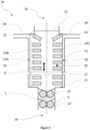
- the two coolings can be done in a device 1 combining a cooling in a tank 2 containing a coolant 3 and a faster cooling in a consecutive cooling device 4 containing a coolant.
- the arrows represent the flat metallic product moving direction.
- US 7 645 417 B2 discloses a cooling device, comprising a tank 5 in which two series (6 and 6') of immersed tubes 7 are vertically stacked on both sides of a strip 8. Said tubes projects onto the strip a coolant in the form of essentially horizontal turbulent jets. Even though a high cooling rate is achieved, greater than 1000°C, this device is not satisfactory because the cooling is not homogeneous in the strip width direction leading to flatness defects. Consequently, there is a need to improve the product flatness of the exiting metallic flat product. Thus, the cooling device 4 needs to be improved.
- sealing means 9 usually isolates the tank 2 and the cooling device 4 to limit the influence of the coolant 3 onto the cooling device 4. Furthermore, the coolant temperature in the cooling device 4 is generally inferior to the one of the tank 2 coolant. Any leakage from one space to another would create temperature gradient negatively impacting the cooling homogeneity.
- EP 1 300 478 B1 extensively describes a sealing means 9 and its advantages.
- the purpose of this invention is to solve the aforementioned problem.
- the equipment can also comprise any characteristics of claims 2 to 9.
- This object is also achieved by providing a method according to claims 10 to 13.
- Figures 2 to 7 do not exhibit all the elements of the cooling device but the main elements permitting to understand the invention and its difference with the known state of the art. For example, the system permitting to flow the coolant into the projecting devices are not represented.
- the invention relates to a cooling device 10 for a cooling operation of a flat metallic product S, said cooling device being located in an essentially vertical, ascending or descending, path comprising:
- the flat metallic product S will be referred as a strip.
- said flat metallic product is not limited to a strip.
- the fast cooling device 10 is used to cool and/or quench a flat metallic product, such as a steel strip.
- the sealing means are not represented in Figure 4 .
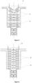
- the cooling device is positioned in an essentially vertical, ascending or descending, path of the flat metallic product. It means that when the flat metallic product passes through the cooling device, its moving direction is essentially vertical as represented by the arrow D.
- the cooling device comprises a tank 15 containing a coolant bath 17 which defines a coolant surface 11.
- the primary role of the tank is to contain a coolant creating a coolant bath.
- the coolant is preferably a liquid and can be water. Its secondary role is to isolate the coolant bath from the exterior which permits to control the coolant parameters, such as the its temperature, and the projected coolant fluxed.
- said tank comprises at least two openings, one on its upper side 16 and one on its bottom side 16', through which said flat metallic product S can go, describing a path.
- the role of those openings is to let the flat metallic product pass through the cooling device 10. They should also prevent the entrance of any external liquid into the coolant bath 17.
- Said openings wherein the strip pass through should be essentially vertically aligned so the strip can have an essentially vertical path. The path described by said flat metallic product is essentially vertical.
- the tank preferably comprises at least two lateral openings (21 and 21') allowing the coolant discharge.
- the opening on the bottom side is equipped with a sealing mean 9 to improve the coolant bath isolation from the exterior.
- the sealing mean can comprise a double pair of rollers (22 and 22') pressed against the strip S and positioned symmetrically relative to the latter.
- a fluid can be injected with a controllable pressure and/or temperature between the rollers.
- two series (18 and 18'), of projecting devices 13 comprising at least an aperture 13E, are facing each other.
- the two series (18 and 18') are on both sides of said flat metallic product vertical path.
- said two series of projecting device are positioned on two opposite tank sides.
- Each series is made of several projecting devices 13 essentially vertically aligned and positioned to homogeneously cool the strip in its width direction W. The projected coolant should be distributed along the strip width to achieve a homogeneous cooling in the strip width direction.
- the coolant is projected through apertures 13E in said projecting devices 13.
- Said apertures 13 are among other possibilities: a slit, a hole or a series of holes.
- Said projecting devices apertures 13E are completely immersed in the coolant bath. Such an immersion permits to suppress or at least lower the gas bubble or vapor formation (and presence) in the coolant bath close to the strip compared to non-immersed apertures. Preferentially said projecting devices are completely immersed in said coolant.
- a gap 19 separates two vertically successive projecting devices (e.g. 13A and 13B) of a series (18 and 18') of projecting device.
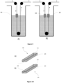
- a gap permits to improve the cooling efficiency of the sprayed coolant by improving the renewal of the coolant in contact to the strip and heat exchange between the projected coolant and the strip. If there was no gap between the projecting device, the coolant could only evacuate by flowing 12' vertically along the strip thus reducing the cooling efficiency, as illustrated in Figure 6 . On the contrary, such a gap permits the discharge of the coolant perpendicularly to the strip surface. Moreover, absence of gap would also promote the creation of turmoil at the bath surface 11'.
- the closest projecting device, of each series, to the coolant bath surface 11 comprised in the tank 15 is referred as the uppermost projecting device (20 and 20').
- the uppermost projecting device (20 and 20') is downwardly inclined of an angle comprised between 20° and 40° to the horizontal.
- Such an inclination of the uppermost projecting device permits to suppress or at least drastically reduce the turmoil generated by the uppermost projecting devices compared to horizontal projecting device as disclosed in US 7 645 417 B2 and illustrated in Figure 7 wherein the bath surface 11" is not flat but exhibits turmoil. Consequently, the cooling homogeneity in the width direction is increased.
- Figure 8 is a simulation a coolant bath surface 11" of a cooling device having a series of projecting devices oriented essentially horizontally; i.e. having coolant sprayed essentially horizontally, wherein the strip is moving upward. This case corresponds to the one of patent US 7 645 417 B2 .
- Such a claimed cooling device 10 is not limit to only one positioned at the strip exit from the cooling device as illustrated in Figure 1 .
- this claimed cooling device 10 can be positioned at the strip entry of the tank 2, as illustrated in Figure 9A .
- two claimed cooling devices can be installed on the entrance and exit of the strip of tank 2, as illustrated in Figure 9B .
- Such a positioning of one or several claimed cooling devices permits to perform various cooling cycles when used in addition of a tank containing water. For example, the three following thermal cycles are possible if the coolant temperature in the cooling device 10 is lower than the one in the tank 2:
- both series (18 and 18') have the same number of projecting devices (13) downwardly inclined of an angle of 20° to 40° compared to the horizontal.
- the inclined projecting device of each series should be facing each other.
- the two uppermost projecting devices of both series (18 and 18') are downwardly inclined of an angle of 20° to 40° compared to the horizontal.
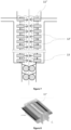
- the two uppermost projecting devices (20 and 20A or 20' and 20'A) of a series correspond to the two immersed projecting devices being the closer to the surface, as illustrated in Figure 4 .
- Such an arrangement permits to increase even further the cooling homogeneity in the strip width.
- the three uppermost projecting devices on both series (18 and 18') are downwardly inclined of an angle of 20° to 40° compared to the horizontal.
- the four uppermost projecting devices on both series (18 and 18') are downwardly inclined of an angle of 20° to 40° compared to the horizontal.
- all projecting devices located up to a depth of 50 cm from the coolant surface are downwardly inclined of an angle of 20° to 40°compared to the horizontal.
- Such an arrangement permits to increase even further the cooling homogeneity in the strip width because the formation of gas bubble is reduced even more.
- all projecting devices located up to a depth of 1 meter or 2 meters or 3 meters from the coolant surface are downwardly inclined of an angle of 20° to 40°compared to the horizontal.
- said series of projecting devices comprises 10 to 40 devices. Such a quantity of devices permits to ensure a sufficient cooling capacity of the cooling device. More advantageously, each projecting device can spray at least 250 m 3 .h -1 of coolant per m 2 of strip.
- said projecting devices are tubes 14.
- said tubes are hollow rectangular cuboid.
- the coolant enters said tubes by opening on their two lateral faces 23, which are preferentially their smallest faces.
- the coolant exits said tubes by a frontal face 24, which is oriented toward the strip.
- said frontal face is equipped with a plate having at least an aperture such as rows of round holes, as illustrated in Figure 9A , and/or at least a slit, as illustrated in Figure 9B .
- said projecting device apertures 13E are at a distance between 30 and 200 mm of said path.
- the path is referring to the path described by the flat metallic product.
- the distance between the apertures of the projecting device and the strip is smaller than 30 mm, the moving strip might contact the cooling device which can lead to scratch or damage the strip surface.
- the distance is greater than 200 mm, the cooling performance is reduced.
- the cooling device does not comprise rolls, such as restraining rolls, between said two openings.
- the invention also relates to a cooling method wherein a flat metallic product moving essentially vertically, ascendingly or descendingly, is cooled in a device as described previously, said series of projecting devices eject a coolant flux between 250 m 3 and 2 500 m 3 per hour per surface of flat product.
- a coolant flux in that range is sufficient to obtain a cooling speed desired to achieve the desired product properties.
- said series of projecting devices eject a coolant having a speed between 0.25 m.s -1 and 20 m.s -1 .
- a speed permits to the ejected coolant to reach the strip surface and being reflected horizontally in the gap between the projecting devices which improves the coolant renewal and thus the cooling homogeneity.
- said series of projecting devices eject a coolant being at a temperature between 10 and 100 °C.
- said cooling device permits to cool said flat metallic product of at least 200°C.s -1 . More preferably, said cooling device permits to cool said flat metallic product of at least 500°C.s -1 . Even more preferably, said cooling device permits to cool said flat metallic product of at least 1000°C.s -1 .
Landscapes
- Chemical & Material Sciences (AREA)
- Engineering & Computer Science (AREA)
- Mechanical Engineering (AREA)
- Physics & Mathematics (AREA)
- Thermal Sciences (AREA)
- Crystallography & Structural Chemistry (AREA)
- Materials Engineering (AREA)
- Metallurgy (AREA)
- Organic Chemistry (AREA)
- Heat Treatment Of Strip Materials And Filament Materials (AREA)
- Heat Treatments In General, Especially Conveying And Cooling (AREA)
Applications Claiming Priority (2)
| Application Number | Priority Date | Filing Date | Title |
|---|---|---|---|
| PCT/IB2019/056684 WO2021024021A1 (en) | 2019-08-06 | 2019-08-06 | Device for cooling a steel strip |
| PCT/IB2020/057132 WO2021024096A1 (en) | 2019-08-06 | 2020-07-29 | Device for cooling a steel strip |
Publications (2)
| Publication Number | Publication Date |
|---|---|
| EP4010504A1 EP4010504A1 (en) | 2022-06-15 |
| EP4010504B1 true EP4010504B1 (en) | 2024-03-20 |
Family
ID=68072866
Family Applications (1)
| Application Number | Title | Priority Date | Filing Date |
|---|---|---|---|
| EP20747149.1A Active EP4010504B1 (en) | 2019-08-06 | 2020-07-29 | Device for cooling a steel strip |
Country Status (12)
| Country | Link |
|---|---|
| US (1) | US12465966B2 (pl) |
| EP (1) | EP4010504B1 (pl) |
| JP (1) | JP7536081B2 (pl) |
| KR (1) | KR102751417B1 (pl) |
| CN (1) | CN114207156A (pl) |
| CA (1) | CA3147283C (pl) |
| ES (1) | ES2978672T3 (pl) |
| MX (1) | MX2022001585A (pl) |
| PL (1) | PL4010504T3 (pl) |
| UA (1) | UA127303C2 (pl) |
| WO (2) | WO2021024021A1 (pl) |
| ZA (1) | ZA202200389B (pl) |
Families Citing this family (1)
| Publication number | Priority date | Publication date | Assignee | Title |
|---|---|---|---|---|
| FR3156805B1 (fr) | 2023-12-13 | 2025-11-07 | Fives Stein | Ligne de galvanisation a refroidissement humide |
Family Cites Families (12)
| Publication number | Priority date | Publication date | Assignee | Title |
|---|---|---|---|---|
| JPS51126934A (en) * | 1975-04-30 | 1976-11-05 | Nippon Kokan Kk | Method of preventing quenchhstain of tin plated steel strip |
| JPS57147261U (pl) * | 1981-03-10 | 1982-09-16 | ||
| JPS59153843A (ja) * | 1983-02-18 | 1984-09-01 | Nippon Kokan Kk <Nkk> | ストリップの冷却装置 |
| JPS609834A (ja) * | 1983-06-28 | 1985-01-18 | Nippon Steel Corp | 鋼ストリツプの冷却方法及びその装置 |
| JPS61217531A (ja) * | 1985-03-22 | 1986-09-27 | Kawasaki Steel Corp | 鋼帯の冷却方法 |
| BE1012215A3 (fr) * | 1998-10-01 | 2000-07-04 | Centre Rech Metallurgique | Procede de refroidissement en continu d'une tole en acier et dispositif pour sa mise en oeuvre. |
| BE1014418A3 (fr) | 2001-10-05 | 2003-10-07 | Cockerill Rech & Dev | Procede et dispositif de refroidissement accelere en recuit continu. |
| EP1538228A1 (fr) * | 2003-12-01 | 2005-06-08 | R & D du groupe Cockerill-Sambre | Procédé et Dispositif de refroidissement d'une bande d'acier |
| DE102008028592B3 (de) * | 2008-06-18 | 2009-12-31 | Wieland-Werke Ag | Abkühleinrichtung mit Dampfsperre für eine Durchlauf-Wärmebehandlungsanlage |
| CN202081147U (zh) * | 2011-04-22 | 2011-12-21 | 宝山钢铁股份有限公司 | 一种带钢水淬冷却装置 |
| WO2016063414A1 (ja) * | 2014-10-24 | 2016-04-28 | 新日鐵住金株式会社 | 溶融めっき鋼板の冷却装置 |
| JP6308287B2 (ja) * | 2015-12-28 | 2018-04-11 | Jfeスチール株式会社 | 急冷焼入れ装置及び急冷焼入れ方法 |
-
2019
- 2019-08-06 WO PCT/IB2019/056684 patent/WO2021024021A1/en not_active Ceased
-
2020
- 2020-07-29 WO PCT/IB2020/057132 patent/WO2021024096A1/en not_active Ceased
- 2020-07-29 CA CA3147283A patent/CA3147283C/en active Active
- 2020-07-29 ES ES20747149T patent/ES2978672T3/es active Active
- 2020-07-29 MX MX2022001585A patent/MX2022001585A/es unknown
- 2020-07-29 EP EP20747149.1A patent/EP4010504B1/en active Active
- 2020-07-29 PL PL20747149.1T patent/PL4010504T3/pl unknown
- 2020-07-29 KR KR1020227003315A patent/KR102751417B1/ko active Active
- 2020-07-29 CN CN202080052381.1A patent/CN114207156A/zh active Pending
- 2020-07-29 US US17/632,180 patent/US12465966B2/en active Active
- 2020-07-29 JP JP2022507388A patent/JP7536081B2/ja active Active
- 2020-07-29 UA UAA202201272A patent/UA127303C2/uk unknown
-
2022
- 2022-01-07 ZA ZA2022/00389A patent/ZA202200389B/en unknown
Also Published As
| Publication number | Publication date |
|---|---|
| BR112022001023A2 (pt) | 2022-04-12 |
| WO2021024096A1 (en) | 2021-02-11 |
| MX2022001585A (es) | 2022-03-11 |
| JP7536081B2 (ja) | 2024-08-19 |
| KR102751417B1 (ko) | 2025-01-07 |
| ZA202200389B (en) | 2022-09-28 |
| UA127303C2 (uk) | 2023-07-12 |
| US12465966B2 (en) | 2025-11-11 |
| KR20220028059A (ko) | 2022-03-08 |
| CA3147283A1 (en) | 2021-02-11 |
| EP4010504A1 (en) | 2022-06-15 |
| WO2021024021A1 (en) | 2021-02-11 |
| PL4010504T3 (pl) | 2024-06-24 |
| US20220226872A1 (en) | 2022-07-21 |
| JP2022543432A (ja) | 2022-10-12 |
| CN114207156A (zh) | 2022-03-18 |
| ES2978672T3 (es) | 2024-09-17 |
| CA3147283C (en) | 2024-02-27 |
Similar Documents
| Publication | Publication Date | Title |
|---|---|---|
| TWI460031B (zh) | 熱軋鋼板之冷卻裝置 | |
| WO2008035510A1 (en) | Cooling method of steel plate | |
| EP3705587A1 (en) | Facility and method for producing thick steel sheet | |
| EP4010504B1 (en) | Device for cooling a steel strip | |
| US10974316B2 (en) | Secondary cooling method and secondary cooling device for casting product in continuous casting | |
| CN202081135U (zh) | 一种带钢冷却装置 | |
| WO2003026813A1 (fr) | Procede et dispositif de refroidissement d'une tole d'acier | |
| JP4870110B2 (ja) | 鋼板冷却装置 | |
| CA1060322A (en) | Method and apparatus for water quenching steel strip with reduced amount of oxidation | |
| KR102559142B1 (ko) | 금속 기판을 냉각하기 위한 프로세스 및 기기 | |
| AU2004294469B2 (en) | Method and device for cooling a steel strip | |
| JP2019210549A (ja) | 鋼板の冷却方法、鋼板の冷却装置および鋼板の製造方法 | |
| JP4214134B2 (ja) | 厚鋼板の冷却装置 | |
| RU2790855C1 (ru) | Устройство для охлаждения стальной полосы | |
| JP3867073B2 (ja) | 熱間圧延鋼板の冷却装置および冷却方法 | |
| JP2004307904A (ja) | 鋼帯の冷却装置 | |
| BR112022001023B1 (pt) | Dispositivo de resfriamento e método de resfriamento | |
| KR101867716B1 (ko) | 냉각장치와 이를 사용하는 열처리장치 및 열처리방법 | |
| JP3905487B2 (ja) | 溶融亜鉛メッキ鋼帯の冷却方法と冷却装置 | |
| JPS5922605B2 (ja) | 鋼板の下面冷却方法 | |
| KR101377099B1 (ko) | 연속 소둔로의 냉각 탱크 | |
| MXPA06006161A (en) | Method and device for cooling a steel strip | |
| JP2001288594A (ja) | 電気錫めっき鋼板のラミナーフローノズル、冷却装置および冷却方法 | |
| JPS61166928A (ja) | 連続焼鈍方法 |
Legal Events
| Date | Code | Title | Description |
|---|---|---|---|
| STAA | Information on the status of an ep patent application or granted ep patent |
Free format text: STATUS: UNKNOWN |
|
| STAA | Information on the status of an ep patent application or granted ep patent |
Free format text: STATUS: THE INTERNATIONAL PUBLICATION HAS BEEN MADE |
|
| PUAI | Public reference made under article 153(3) epc to a published international application that has entered the european phase |
Free format text: ORIGINAL CODE: 0009012 |
|
| STAA | Information on the status of an ep patent application or granted ep patent |
Free format text: STATUS: REQUEST FOR EXAMINATION WAS MADE |
|
| 17P | Request for examination filed |
Effective date: 20220307 |
|
| AK | Designated contracting states |
Kind code of ref document: A1 Designated state(s): AL AT BE BG CH CY CZ DE DK EE ES FI FR GB GR HR HU IE IS IT LI LT LU LV MC MK MT NL NO PL PT RO RS SE SI SK SM TR |
|
| DAV | Request for validation of the european patent (deleted) | ||
| DAX | Request for extension of the european patent (deleted) | ||
| GRAP | Despatch of communication of intention to grant a patent |
Free format text: ORIGINAL CODE: EPIDOSNIGR1 |
|
| STAA | Information on the status of an ep patent application or granted ep patent |
Free format text: STATUS: GRANT OF PATENT IS INTENDED |
|
| INTG | Intention to grant announced |
Effective date: 20231013 |
|
| P01 | Opt-out of the competence of the unified patent court (upc) registered |
Effective date: 20231223 |
|
| GRAS | Grant fee paid |
Free format text: ORIGINAL CODE: EPIDOSNIGR3 |
|
| GRAA | (expected) grant |
Free format text: ORIGINAL CODE: 0009210 |
|
| STAA | Information on the status of an ep patent application or granted ep patent |
Free format text: STATUS: THE PATENT HAS BEEN GRANTED |
|
| AK | Designated contracting states |
Kind code of ref document: B1 Designated state(s): AL AT BE BG CH CY CZ DE DK EE ES FI FR GB GR HR HU IE IS IT LI LT LU LV MC MK MT NL NO PL PT RO RS SE SI SK SM TR |
|
| REG | Reference to a national code |
Ref country code: GB Ref legal event code: FG4D |
|
| REG | Reference to a national code |
Ref country code: CH Ref legal event code: EP |
|
| REG | Reference to a national code |
Ref country code: IE Ref legal event code: FG4D |
|
| REG | Reference to a national code |
Ref country code: DE Ref legal event code: R096 Ref document number: 602020027543 Country of ref document: DE |
|
| REG | Reference to a national code |
Ref country code: SE Ref legal event code: TRGR |
|
| REG | Reference to a national code |
Ref country code: NL Ref legal event code: FP |
|
| PG25 | Lapsed in a contracting state [announced via postgrant information from national office to epo] |
Ref country code: LT Free format text: LAPSE BECAUSE OF FAILURE TO SUBMIT A TRANSLATION OF THE DESCRIPTION OR TO PAY THE FEE WITHIN THE PRESCRIBED TIME-LIMIT Effective date: 20240320 |
|
| REG | Reference to a national code |
Ref country code: LT Ref legal event code: MG9D |
|
| PG25 | Lapsed in a contracting state [announced via postgrant information from national office to epo] |
Ref country code: GR Free format text: LAPSE BECAUSE OF FAILURE TO SUBMIT A TRANSLATION OF THE DESCRIPTION OR TO PAY THE FEE WITHIN THE PRESCRIBED TIME-LIMIT Effective date: 20240621 |
|
| PG25 | Lapsed in a contracting state [announced via postgrant information from national office to epo] |
Ref country code: RS Free format text: LAPSE BECAUSE OF FAILURE TO SUBMIT A TRANSLATION OF THE DESCRIPTION OR TO PAY THE FEE WITHIN THE PRESCRIBED TIME-LIMIT Effective date: 20240620 Ref country code: HR Free format text: LAPSE BECAUSE OF FAILURE TO SUBMIT A TRANSLATION OF THE DESCRIPTION OR TO PAY THE FEE WITHIN THE PRESCRIBED TIME-LIMIT Effective date: 20240320 |
|
| PG25 | Lapsed in a contracting state [announced via postgrant information from national office to epo] |
Ref country code: RS Free format text: LAPSE BECAUSE OF FAILURE TO SUBMIT A TRANSLATION OF THE DESCRIPTION OR TO PAY THE FEE WITHIN THE PRESCRIBED TIME-LIMIT Effective date: 20240620 Ref country code: NO Free format text: LAPSE BECAUSE OF FAILURE TO SUBMIT A TRANSLATION OF THE DESCRIPTION OR TO PAY THE FEE WITHIN THE PRESCRIBED TIME-LIMIT Effective date: 20240620 Ref country code: LT Free format text: LAPSE BECAUSE OF FAILURE TO SUBMIT A TRANSLATION OF THE DESCRIPTION OR TO PAY THE FEE WITHIN THE PRESCRIBED TIME-LIMIT Effective date: 20240320 Ref country code: HR Free format text: LAPSE BECAUSE OF FAILURE TO SUBMIT A TRANSLATION OF THE DESCRIPTION OR TO PAY THE FEE WITHIN THE PRESCRIBED TIME-LIMIT Effective date: 20240320 Ref country code: GR Free format text: LAPSE BECAUSE OF FAILURE TO SUBMIT A TRANSLATION OF THE DESCRIPTION OR TO PAY THE FEE WITHIN THE PRESCRIBED TIME-LIMIT Effective date: 20240621 Ref country code: FI Free format text: LAPSE BECAUSE OF FAILURE TO SUBMIT A TRANSLATION OF THE DESCRIPTION OR TO PAY THE FEE WITHIN THE PRESCRIBED TIME-LIMIT Effective date: 20240320 Ref country code: BG Free format text: LAPSE BECAUSE OF FAILURE TO SUBMIT A TRANSLATION OF THE DESCRIPTION OR TO PAY THE FEE WITHIN THE PRESCRIBED TIME-LIMIT Effective date: 20240320 |
|
| PG25 | Lapsed in a contracting state [announced via postgrant information from national office to epo] |
Ref country code: LV Free format text: LAPSE BECAUSE OF FAILURE TO SUBMIT A TRANSLATION OF THE DESCRIPTION OR TO PAY THE FEE WITHIN THE PRESCRIBED TIME-LIMIT Effective date: 20240320 |
|
| REG | Reference to a national code |
Ref country code: AT Ref legal event code: UEP Ref document number: 1667877 Country of ref document: AT Kind code of ref document: T Effective date: 20240320 |
|
| REG | Reference to a national code |
Ref country code: ES Ref legal event code: FG2A Ref document number: 2978672 Country of ref document: ES Kind code of ref document: T3 Effective date: 20240917 |
|
| PG25 | Lapsed in a contracting state [announced via postgrant information from national office to epo] |
Ref country code: IS Free format text: LAPSE BECAUSE OF FAILURE TO SUBMIT A TRANSLATION OF THE DESCRIPTION OR TO PAY THE FEE WITHIN THE PRESCRIBED TIME-LIMIT Effective date: 20240720 |
|
| PG25 | Lapsed in a contracting state [announced via postgrant information from national office to epo] |
Ref country code: PT Free format text: LAPSE BECAUSE OF FAILURE TO SUBMIT A TRANSLATION OF THE DESCRIPTION OR TO PAY THE FEE WITHIN THE PRESCRIBED TIME-LIMIT Effective date: 20240722 Ref country code: SM Free format text: LAPSE BECAUSE OF FAILURE TO SUBMIT A TRANSLATION OF THE DESCRIPTION OR TO PAY THE FEE WITHIN THE PRESCRIBED TIME-LIMIT Effective date: 20240320 |
|
| PG25 | Lapsed in a contracting state [announced via postgrant information from national office to epo] |
Ref country code: EE Free format text: LAPSE BECAUSE OF FAILURE TO SUBMIT A TRANSLATION OF THE DESCRIPTION OR TO PAY THE FEE WITHIN THE PRESCRIBED TIME-LIMIT Effective date: 20240320 |
|
| PG25 | Lapsed in a contracting state [announced via postgrant information from national office to epo] |
Ref country code: SM Free format text: LAPSE BECAUSE OF FAILURE TO SUBMIT A TRANSLATION OF THE DESCRIPTION OR TO PAY THE FEE WITHIN THE PRESCRIBED TIME-LIMIT Effective date: 20240320 Ref country code: PT Free format text: LAPSE BECAUSE OF FAILURE TO SUBMIT A TRANSLATION OF THE DESCRIPTION OR TO PAY THE FEE WITHIN THE PRESCRIBED TIME-LIMIT Effective date: 20240722 Ref country code: IS Free format text: LAPSE BECAUSE OF FAILURE TO SUBMIT A TRANSLATION OF THE DESCRIPTION OR TO PAY THE FEE WITHIN THE PRESCRIBED TIME-LIMIT Effective date: 20240720 Ref country code: EE Free format text: LAPSE BECAUSE OF FAILURE TO SUBMIT A TRANSLATION OF THE DESCRIPTION OR TO PAY THE FEE WITHIN THE PRESCRIBED TIME-LIMIT Effective date: 20240320 |
|
| REG | Reference to a national code |
Ref country code: DE Ref legal event code: R097 Ref document number: 602020027543 Country of ref document: DE |
|
| PG25 | Lapsed in a contracting state [announced via postgrant information from national office to epo] |
Ref country code: DK Free format text: LAPSE BECAUSE OF FAILURE TO SUBMIT A TRANSLATION OF THE DESCRIPTION OR TO PAY THE FEE WITHIN THE PRESCRIBED TIME-LIMIT Effective date: 20240320 |
|
| PLBE | No opposition filed within time limit |
Free format text: ORIGINAL CODE: 0009261 |
|
| STAA | Information on the status of an ep patent application or granted ep patent |
Free format text: STATUS: NO OPPOSITION FILED WITHIN TIME LIMIT |
|
| PG25 | Lapsed in a contracting state [announced via postgrant information from national office to epo] |
Ref country code: DK Free format text: LAPSE BECAUSE OF FAILURE TO SUBMIT A TRANSLATION OF THE DESCRIPTION OR TO PAY THE FEE WITHIN THE PRESCRIBED TIME-LIMIT Effective date: 20240320 |
|
| PG25 | Lapsed in a contracting state [announced via postgrant information from national office to epo] |
Ref country code: MC Free format text: LAPSE BECAUSE OF FAILURE TO SUBMIT A TRANSLATION OF THE DESCRIPTION OR TO PAY THE FEE WITHIN THE PRESCRIBED TIME-LIMIT Effective date: 20240320 |
|
| 26N | No opposition filed |
Effective date: 20241223 |
|
| REG | Reference to a national code |
Ref country code: CH Ref legal event code: PL |
|
| PG25 | Lapsed in a contracting state [announced via postgrant information from national office to epo] |
Ref country code: LU Free format text: LAPSE BECAUSE OF NON-PAYMENT OF DUE FEES Effective date: 20240729 |
|
| PG25 | Lapsed in a contracting state [announced via postgrant information from national office to epo] |
Ref country code: LU Free format text: LAPSE BECAUSE OF NON-PAYMENT OF DUE FEES Effective date: 20240729 |
|
| PG25 | Lapsed in a contracting state [announced via postgrant information from national office to epo] |
Ref country code: SI Free format text: LAPSE BECAUSE OF FAILURE TO SUBMIT A TRANSLATION OF THE DESCRIPTION OR TO PAY THE FEE WITHIN THE PRESCRIBED TIME-LIMIT Effective date: 20240320 Ref country code: CH Free format text: LAPSE BECAUSE OF NON-PAYMENT OF DUE FEES Effective date: 20240731 |
|
| PGFP | Annual fee paid to national office [announced via postgrant information from national office to epo] |
Ref country code: PL Payment date: 20250626 Year of fee payment: 6 |
|
| PGFP | Annual fee paid to national office [announced via postgrant information from national office to epo] |
Ref country code: GB Payment date: 20250619 Year of fee payment: 6 |
|
| PGFP | Annual fee paid to national office [announced via postgrant information from national office to epo] |
Ref country code: NL Payment date: 20250620 Year of fee payment: 6 Ref country code: BE Payment date: 20250619 Year of fee payment: 6 |
|
| PGFP | Annual fee paid to national office [announced via postgrant information from national office to epo] |
Ref country code: FR Payment date: 20250619 Year of fee payment: 6 |
|
| PGFP | Annual fee paid to national office [announced via postgrant information from national office to epo] |
Ref country code: TR Payment date: 20250627 Year of fee payment: 6 Ref country code: SK Payment date: 20250625 Year of fee payment: 6 |
|
| PG25 | Lapsed in a contracting state [announced via postgrant information from national office to epo] |
Ref country code: IE Free format text: LAPSE BECAUSE OF NON-PAYMENT OF DUE FEES Effective date: 20240729 |
|
| PGFP | Annual fee paid to national office [announced via postgrant information from national office to epo] |
Ref country code: SE Payment date: 20250619 Year of fee payment: 6 |
|
| PGFP | Annual fee paid to national office [announced via postgrant information from national office to epo] |
Ref country code: ES Payment date: 20250801 Year of fee payment: 6 |
|
| PGFP | Annual fee paid to national office [announced via postgrant information from national office to epo] |
Ref country code: DE Payment date: 20250620 Year of fee payment: 6 |
|
| PGFP | Annual fee paid to national office [announced via postgrant information from national office to epo] |
Ref country code: IT Payment date: 20250619 Year of fee payment: 6 |
|
| PGFP | Annual fee paid to national office [announced via postgrant information from national office to epo] |
Ref country code: AT Payment date: 20250623 Year of fee payment: 6 |
|
| PGFP | Annual fee paid to national office [announced via postgrant information from national office to epo] |
Ref country code: CZ Payment date: 20250701 Year of fee payment: 6 |
|
| PGFP | Annual fee paid to national office [announced via postgrant information from national office to epo] |
Ref country code: RO Payment date: 20250701 Year of fee payment: 6 |
|
| PG25 | Lapsed in a contracting state [announced via postgrant information from national office to epo] |
Ref country code: CY Free format text: LAPSE BECAUSE OF FAILURE TO SUBMIT A TRANSLATION OF THE DESCRIPTION OR TO PAY THE FEE WITHIN THE PRESCRIBED TIME-LIMIT; INVALID AB INITIO Effective date: 20200729 |
|
| PG25 | Lapsed in a contracting state [announced via postgrant information from national office to epo] |
Ref country code: HU Free format text: LAPSE BECAUSE OF FAILURE TO SUBMIT A TRANSLATION OF THE DESCRIPTION OR TO PAY THE FEE WITHIN THE PRESCRIBED TIME-LIMIT; INVALID AB INITIO Effective date: 20200729 |