EP4006647B1 - Drückerkrone für uhr - Google Patents
Drückerkrone für uhr Download PDFInfo
- Publication number
- EP4006647B1 EP4006647B1 EP20209679.8A EP20209679A EP4006647B1 EP 4006647 B1 EP4006647 B1 EP 4006647B1 EP 20209679 A EP20209679 A EP 20209679A EP 4006647 B1 EP4006647 B1 EP 4006647B1
- Authority
- EP
- European Patent Office
- Prior art keywords
- crown
- push
- button
- cage
- base
- Prior art date
- Legal status (The legal status is an assumption and is not a legal conclusion. Google has not performed a legal analysis and makes no representation as to the accuracy of the status listed.)
- Active
Links
- 230000000295 complement effect Effects 0.000 claims description 2
- 230000006835 compression Effects 0.000 claims description 2
- 238000007906 compression Methods 0.000 claims description 2
- 230000000994 depressogenic effect Effects 0.000 description 2
- 238000007790 scraping Methods 0.000 description 2
- 241000310247 Amyna axis Species 0.000 description 1
- 206010063493 Premature ageing Diseases 0.000 description 1
- 208000032038 Premature aging Diseases 0.000 description 1
- 230000000903 blocking effect Effects 0.000 description 1
- 238000006073 displacement reaction Methods 0.000 description 1
- 230000000694 effects Effects 0.000 description 1
- 230000002028 premature Effects 0.000 description 1
- 230000001737 promoting effect Effects 0.000 description 1
- 238000004804 winding Methods 0.000 description 1
Images


Classifications
-
- G—PHYSICS
- G04—HOROLOGY
- G04B—MECHANICALLY-DRIVEN CLOCKS OR WATCHES; MECHANICAL PARTS OF CLOCKS OR WATCHES IN GENERAL; TIME PIECES USING THE POSITION OF THE SUN, MOON OR STARS
- G04B3/00—Normal winding of clockworks by hand or mechanically; Winding up several mainsprings or driving weights simultaneously
- G04B3/04—Rigidly-mounted keys, knobs or crowns
- G04B3/046—Operation by rotation and axial movement with extra function of axial shift of operating element, e.g. crown combined with push button
-
- G—PHYSICS
- G04—HOROLOGY
- G04B—MECHANICALLY-DRIVEN CLOCKS OR WATCHES; MECHANICAL PARTS OF CLOCKS OR WATCHES IN GENERAL; TIME PIECES USING THE POSITION OF THE SUN, MOON OR STARS
- G04B3/00—Normal winding of clockworks by hand or mechanically; Winding up several mainsprings or driving weights simultaneously
- G04B3/04—Rigidly-mounted keys, knobs or crowns
- G04B3/043—Locking of the operating element, also by mounting in a concealed place
-
- G—PHYSICS
- G04—HOROLOGY
- G04C—ELECTROMECHANICAL CLOCKS OR WATCHES
- G04C3/00—Electromechanical clocks or watches independent of other time-pieces and in which the movement is maintained by electric means
- G04C3/001—Electromechanical switches for setting or display
- G04C3/004—Magnetically controlled
-
- G—PHYSICS
- G04—HOROLOGY
- G04C—ELECTROMECHANICAL CLOCKS OR WATCHES
- G04C3/00—Electromechanical clocks or watches independent of other time-pieces and in which the movement is maintained by electric means
- G04C3/008—Mounting, assembling of components
-
- G—PHYSICS
- G04—HOROLOGY
- G04G—ELECTRONIC TIME-PIECES
- G04G21/00—Input or output devices integrated in time-pieces
- G04G21/08—Touch switches specially adapted for time-pieces
Definitions
- the present invention relates to the field of watchmaking and more specifically to an arrangement of a spring within a push-crown and the means making it possible to accompany the rotation of the push-crown with a click.
- the push-crowns fitted to timepieces are fitted with a return spring which is positioned around the stem of the crown.
- the spring generally bears at one end under the crown head and at its other end on a bearing surface of the crown tube or on a washer arranged on this same bearing surface. In use, the relative movement between the spring and the rotating components of the pusher-crown causes a scraping phenomenon and thereby premature wear of the spring.
- a crown-pusher provided with a spring disposed within a cage integral in rotation with the movement of the head, the spring being arranged within the cage so as to be driven in rotation with the cage.
- This arrangement of the spring within a cage makes it possible to avoid a scraping effect between the spring and the winding bottom of the crown and thereby to increase the life of the spring. Since the cage rotates with the spring when an action is performed on the push-crown, the spring is not subject to relative movement with a component.
- the cage having faces of a shape similar to that of the faces on which it bears, normal friction is present in the bearing zone, which makes it possible to guarantee continuous driving of the ring gear.
- the push-crowns fitted with the spring cage according to the aforementioned application are fitted, among other things, to electronic watches.
- the crown pusher is then kinematically linked to a multipolar magnet intended to cooperate with one or more sensors.
- the rotation of the push-crown is therefore not subjected to mechanical resistance with, as a corollary, that the user may have the impression of turning the head of the push-crown in a vacuum.
- the object of the present invention is to improve the crown pusher provided with the spring cage according to the prior art.
- the base of the spring cage is provided with cells cooperating with protrusions formed in a washer arranged on the seat of the tube of the push-button crown.
- the rotation of the push-crown is then accompanied by a click when the protrusions pass through the cells, which allows the user to ensure that the head of the push-crown is actually rotating.
- the shape of the protuberances and the corresponding cells has been determined by finite elements to guarantee a click without the risk of blocking the crown due to the force of the spring.
- the number of these protuberances and corresponding dimples has also been determined to adjust the desired torque. These parameters were associated with the theoretical speeds of rotation of the pusher-crown and with tests to avoid the entry into resonance of the system as well as not to penalize the fatigue life of the spring.
- This design with a washer makes it possible to adjust the design of the washer on the basis of several technical parameters by modifying only one part which is the washer and not the entire system of the pusher-crown.
- the present invention relates to a push-crown intended to equip a timepiece.
- the rotation of the push-crown is accompanied by a "click" allowing the user to feel that he has correctly actuated the push-crown.
- the push-crown according to the invention is more specifically suitable for an application where the actuation takes place without mechanical resistance, for example for an electronic watch or for a mechanical watch provided with a magnetic push-crown.
- the timepiece conventionally comprises a case 1 fitted with a middle part 2 and a push-piece crown 3 comprising a recessed head 4 secured to a stem 7 moving in a tube 6 fixed to the middle part.
- the tube 6 is crossed by the rod 7 connected to the hollow head 4.
- the hollow head 4 is mounted so as to be able to move in translation and in rotation respectively along and around the axis 7a of the rod 7.
- stem 7 is fixed at its base to a retaining element 8.
- a magnet 9 for example a multipolar magnet, is fixed to the distal end of stem 7 intended to cooperate with one or more sensors (not shown).
- the stem can actuate a function such as a chronograph function.
- the push-button crown 3 further comprises a spring 10 arranged around the rod 7.
- the return spring 10 is mounted in compression within a cage 11 visible in more detail at picture 3 .
- the cage 11 is arranged between the tube 6 and the rod 7. It bears at one axial end on an inner face of the hollow head 4 and at its other axial end on a seat 6a of the tube 6 or, preferably, on a washer 14 promoting sliding, washer 14 being arranged on this same seat 6a.
- the cage 11 is made in two distinct upper 12 and lower 13 parts with the upper part 12 integral with the hollowed head 4.
- the upper part 12 is fixed to a core 5 extending partially around the rod 7 from the inner face of the recessed head 4.
- the two upper 12 and lower 13 parts cooperate or, in other words, fit together.
- the upper part 12 of the cage is integral in rotation with the hollow head 4, while the lower part 13 of the cage is axially free with respect to the hollow head but driven in rotation by the upper part of the cage during rotation hollowed out head.
- the upper part 12 is mounted on the lower part 13 so as to be able to move in translation along the axis 7a of the rod 7 when the push-button crown is depressed.
- Different configurations are possible to ensure the rotational cooperation of the two parts and the translational movement of the upper part relative to the lower part.
- the upper part 12 has at least one portion 12f nested in an opening 13b of the lower part 13.
- the upper part may have at least one sliding portion within a slide provided on an inner wall of the lower part.
- each part 12, 13 has a cylindrical shape with a side wall 12a, 13a provided with at least one opening 12b, 13b and preferably two openings, or even three, four, etc. openings.
- the side wall 12a, 13a is delimited at one end by a base 12c, 13c pierced with a central hole and at the other end by a completely open base 12d, 13d.
- the openings 12b, 13b cut in the side wall 12a, 13a define the contours of a U. In the example shown, the two openings are diametrically opposed.
- the openings 12b, 13b are delimited by portions 12f, 13f of the side wall 12a, 13a.
- the side wall 12a, 13a is thus formed of portions 12f, 13f framed by the openings 12b, 13b.
- the two 12,13 parts are mounted in opposite directions relative to each other, coaxially along the rod 7 and with an angular displacement of 90 ° relative to each other.
- the open bases 12d, 13d face each other and the portions 12f of the side wall 12a of the upper part 12 are nested in the openings 13b of the side wall 13a of the lower part 13 so as, on the one hand, to allow the movement in translation of the upper part relative to the lower part and, on the other hand, so that the upper part in rotation can drive the lower part in its movement.
- the spring 10 is housed in the cage 11 between the two pierced bases of the central hole 12c, 13c in the space delimited by the side walls 12a, 13a and the rim 12e, 13e of the central holes. This arrangement allows in use to rotate the spring with the cage, which prevents its premature aging caused by a relative movement between the spring and a rotating component.
- the cage 11 comprises on the base 13c of its lower part 13, and more precisely on the face of the cage facing the seat 6a, cells 18 intended to cooperate with protrusions 17 provided in the washer 14 as shown in figures 3, 4 And 7 .
- the protuberances and the cells are present in the same number and are of complementary shape so as to fit into each other. Thanks to the protuberances passing from cells to cells, the rotation of the push-crown is accompanied by a click.
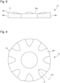
- the cells and the protuberances are distributed with a regular angular interval respectively on the base 13c of the cage 13 and the upper face 14a of the washer 14.
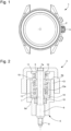
- the protuberances and the cells in projection in the plane of the base and of the puck have an oval shape with a rim widening towards the perimeter of the puck and the base.
- the cells and the protuberances have a cross-section in the form of an arc of a circle, the arc of a circle having an increasing length in the direction of the perimeter of the washer and of the base of the cage.
- transverse is meant the direction perpendicular to the radial direction and the direction parallel to the axis 7a of the rod 7.
- the cells and the protuberances are distributed over the periphery of the base of the cage and of the upper face of the washer. More preferably, the protuberances and the cells open out onto the perimeter respectively of the washer and of the base of the cage.
- the cells 18 are dug in the thickness of the bevel 13g of the base 13C of the lower part 13 of the cage ( fig.4 ). Along its axis of symmetry 18a towards the periphery of the base, the cell 18 has a depth that increases linearly from the plane of the base to a depth corresponding to the thickness of the bevel 13g at the periphery ( fig.6B ).
- the washer 14 comprises curved protuberances 17 intended to be housed in the cells 18.
- the protrusions 17 have an increasing thickness along their axis of symmetry 17a until they emerge on the perimeter of the washer 14 with a vertical wall in an arc of a circle 17b aligned with the vertical wall 14b of the washer ( figs. 3 , 7 And 8 ).
- the vertical wall 14b of the washer is also provided with lugs 19 extending radially, the lugs being intended to block the washer in rotation within the tube ( figs. 7 And 9 ).
- the protrusions could be provided on the base of the cage and the cells in the washer without departing from the scope of the invention.
- the present invention does not exclude the protrusions from being machined directly in the seat of the tube, the crown-pusher then being devoid of a washer.
Landscapes
- Physics & Mathematics (AREA)
- General Physics & Mathematics (AREA)
- Electric Clocks (AREA)
- Prostheses (AREA)
Claims (18)
- Drückerkrone (3), umfassend:- ein Rohr (6), das dazu bestimmt ist, an einem Uhrgehäuse (1) befestigt zu werden,- einen ausgehöhlten Kopf (4), der fest mit einer Welle (7) verbunden ist, welche sich in seinem ausgehöhlten Teil erstreckt, wobei die Welle (7) eine Achse (7a) definiert, wobei der ausgehöhlte Kopf (4) dreh- und translationsbeweglich um die bzw. entlang der Achse (7a) der Welle (7) angebracht ist,- eine Rückzugfeder (10), die um die Welle (7) herum angeordnet ist,- ein Gestell (11), das die Feder (10) beherbergt, wobei das Gestell (11) von der Welle (7) durchquert wird und einen oberen Teil (12), der fest mit dem ausgehöhlten Kopf (4) verbunden ist, und einen unteren Teil (13) umfasst, der in Bezug auf den ausgehöhlten Kopf (4) frei angebracht ist, wobei der obere Teil (12) so mit dem unteren Teil (13) zusammenwirkt, dass er den unteren Teil (13) in seiner Drehbewegung antreiben kann, und so, dass er sich in Bezug auf den unteren Teil (13) entlang der Achse (7a) translatorisch bewegen kann, wobei die Feder (10) unter Druck so im Gestell (11) angebracht ist, dass sie zusammen mit dem Gestell (11) drehend angetrieben wird,- wobei das Gestell (11) an einem axialen Ende an einer Innenseite des ausgehöhlten Kopfes (4) und an seinem anderen axialen Ende an einer Unterlagscheibe (14), die an einer Auflage (6a) des Rohres (6) angeordnet ist, aufliegt, wobei das Aufliegen zwischen dem Gestell (11) und der Unterlagscheibe (14) zwischen einer Basis (13c) des unteren Teils (13) des Gestells (11) und einer Oberseite (14a) der Unterlagscheibe (14) stattfindet,- und wobei die Oberseite (14a) der Unterlagscheibe (14) und die Basis (13c) des Gestells (11) Vorsprünge (17) bzw. Aushöhlungen (18), oder umgekehrt Aushöhlungen (18) bzw. Vorsprünge (17) umfassen, wobei die Vorsprünge (17) bei der Drehung der Drückerkrone (3) so mit den Aushöhlungen (18) zusammenwirken, dass sie ein Klicken erzeugen.
- Drückerkrone (3) nach dem vorstehenden Anspruch, dadurch gekennzeichnet, dass die Anzahl von Vorsprüngen (17) und Aushöhlungen (18) gleich ist, und dadurch, dass die Vorsprünge (17) und die Aushöhlungen (18) von komplementärer Form sind, sodass sie ineinandergreifen.
- Drückerkrone (3) nach Anspruch 1 oder 2, dadurch gekennzeichnet, dass die Vorsprünge (17) und die Aushöhlungen (18) mit einem regelmäßigen Winkelintervall jeweils an entweder der Basis (13c) des unteren Teils (13) des Gestells (11) oder der Oberseite (14a) der Unterlagscheibe (14) verteilt sind.
- Drückerkrone (3) nach einem der vorstehenden Ansprüche, dadurch gekennzeichnet, dass die Vorsprünge (17) und die Aushöhlungen (18) jeweils am Umfang entweder der Basis (13c) oder der Oberseite (14a) der Unterlagscheibe (14) verteilt sind.
- Drückerkrone (3) nach einem der vorstehenden Ansprüche, dadurch gekennzeichnet, dass die Vorsprünge (17) und die Aushöhlungen (18) jeweils am Umfang entweder der Basis (13c) oder der Oberseite (14a) der Unterlagscheibe (14) münden.
- Drückerkrone (3) nach einem der vorstehenden Ansprüche, dadurch gekennzeichnet, dass die Vorsprünge (17) und die Aushöhlungen (18) in der zur Achse (7a) parallelen Richtung einen kreisbogenförmigen Schnitt aufweisen.
- Drückerkrone (3) nach dem vorstehenden Anspruch, dadurch gekennzeichnet, dass der Kreisbogen eine in Richtung des Umfangs der Basis (13c) und der Oberseite (14a) der Unterlagscheibe (14) zunehmende Länge aufweist.
- Drückerkrone (3) nach einem der vorstehenden Ansprüche, dadurch gekennzeichnet, dass die Vorsprünge (17) und die Aushöhlungen (18) eine Höhe bzw. eine Tiefe aufweisen, die in einer radialen Richtung zum Umfang der Basis (13c) und der Oberseite (14a) der Unterlagscheibe (14) hin zunimmt.
- Drückerkrone (3) nach einem der vorstehenden Ansprüche, dadurch gekennzeichnet, dass die Vorsprünge (17) und die Aushöhlungen (18) an der Oberseite (14a) der Unterlagscheibe (14) bzw. der Basis (13c) des unteren Teils (13) des Gestells (11) ausgestaltet sind.
- Drückerkrone (3) nach dem vorstehenden Anspruch, dadurch gekennzeichnet, dass der Umfang der Basis (13c) als Abschrägung (13g) gefräst ist, wobei die Aushöhlungen (18) im Bereich des Umfangs der Basis (13c) und ihrer Symmetrieachse (18a) eine Tiefe aufweisen, die der Dicke der Abschrägung (13g) entspricht.
- Drückerkrone (3) nach einem der vorstehenden Ansprüche, dadurch gekennzeichnet, dass der obere Teil (12) und der untere Teil (13) die gleiche zylindrische Form mit einer Seitenwand (12a, 13a) aufweisen, die mit mindestens einer Öffnung (12b, 13b) versehen ist, wobei die Seitenwand (12a, 13a) an einem Ende von der Basis, die mit einem Mittelloch (12c, 13c) für den Durchtritt der Welle (7) durchbohrt ist, und am anderen Ende von einer anderen, vollständig offenen Basis (12d, 13d) begrenzt wird, wobei der obere Teil (12) und der untere Teil (13) in Bezug zueinander in umgekehrter Richtung und koaxial um die Welle (7) angebracht sind, wobei ein Abschnitt (12f) der Seitenwand (12a) des oberen Teils (12) in eine Öffnung (13b) der Seitenwand (13a) des unteren Teils (13) eingreift.
- Drückerkrone (3) nach dem vorstehenden Anspruch, dadurch gekennzeichnet, dass die Öffnung (12b, 13b) die Umrisse eines U definiert.
- Drückerkrone (3) nach Anspruch 11 oder 12, dadurch gekennzeichnet, dass es zwei Öffnungen (12b, 13b) im oberen Teil (12) und im unteren Teil (13) gibt, wobei die Öffnungen (12b, 13b) jedes Teils (12, 13) in Bezug auf die Achse (7a) der Welle (7) diametral gegenüberliegen.
- Drückerkrone (3) nach einem der vorstehenden Ansprüche, dadurch gekennzeichnet, dass das Gestell (11) in seinem oberen Teil (12) an einem Kern (5) befestigt ist, der sich von der Innenseite des ausgehöhlten Kopfes (4) erstreckt und um die Welle (7) herum angeordnet ist.
- Drückerkrone (3) nach einem der Ansprüche 11 bis 14, dadurch gekennzeichnet, dass die Feder (10) im Gestell (11) zwischen der Basis und der anderen Basis, welche jeweils mit dem Mittelloch (12c, 13c) durchbohrt sind, in dem von den Seitenwänden (12a, 13a) und einem Rand (12e, 13e) der Mittellöcher begrenzten Raum aufgenommen ist.
- Drückerkrone (3) nach einem der Ansprüche 11 bis 15, dadurch gekennzeichnet, dass der Abschnitt (12f) der Seitenwand (12a) des oberen Teils (12) teilweise in die Öffnung (13b) des unteren Teils (13) eingerückt ist, wenn sich der ausgehöhlte Kopf (4) in seiner axial am weitesten vom Rohr (6) entfernten Position befindet, wobei der Abschnitt (12f) der Seitenwand (12a) des oberen Teils (12) tiefer in die Öffnung (13b) des unteren Teils (13) eingerückt ist, wenn sich der ausgehöhlte Kopf (4) in seiner axial am nähesten am Rohr (6) liegenden Position befindet.
- 17. Elektronische oder mechanische Uhr, die die Drückerkrone (3) nach einem der vorstehenden Ansprüche umfasst.
- 18. Mechanische Uhr nach dem vorstehenden Anspruch, dadurch gekennzeichnet, dass sie eine magnetische Drückerkrone umfasst.
Priority Applications (4)
| Application Number | Priority Date | Filing Date | Title |
|---|---|---|---|
| EP20209679.8A EP4006647B1 (de) | 2020-11-25 | 2020-11-25 | Drückerkrone für uhr |
| US17/369,041 US11762335B2 (en) | 2020-11-25 | 2021-07-07 | Crown-push-button for a timepiece |
| JP2021119358A JP7186834B2 (ja) | 2020-11-25 | 2021-07-20 | 計時器のリュウズ押しボタン |
| CN202111412058.3A CN114545755A (zh) | 2020-11-25 | 2021-11-25 | 用于时计的表冠按钮 |
Applications Claiming Priority (1)
| Application Number | Priority Date | Filing Date | Title |
|---|---|---|---|
| EP20209679.8A EP4006647B1 (de) | 2020-11-25 | 2020-11-25 | Drückerkrone für uhr |
Publications (2)
| Publication Number | Publication Date |
|---|---|
| EP4006647A1 EP4006647A1 (de) | 2022-06-01 |
| EP4006647B1 true EP4006647B1 (de) | 2023-05-10 |
Family
ID=73597865
Family Applications (1)
| Application Number | Title | Priority Date | Filing Date |
|---|---|---|---|
| EP20209679.8A Active EP4006647B1 (de) | 2020-11-25 | 2020-11-25 | Drückerkrone für uhr |
Country Status (4)
| Country | Link |
|---|---|
| US (1) | US11762335B2 (de) |
| EP (1) | EP4006647B1 (de) |
| JP (1) | JP7186834B2 (de) |
| CN (1) | CN114545755A (de) |
Citations (2)
| Publication number | Priority date | Publication date | Assignee | Title |
|---|---|---|---|---|
| US20100187074A1 (en) * | 2008-12-31 | 2010-07-29 | Suunto Oy | Two-function controlling device for a wrist computer or alike and method for controlling a wrist computer or suchlike terminal |
| EP3339966B1 (de) * | 2016-12-23 | 2020-06-24 | Rolex Sa | Drucktaste für eine uhr |
Family Cites Families (18)
| Publication number | Priority date | Publication date | Assignee | Title |
|---|---|---|---|---|
| CH692068A5 (fr) * | 1998-03-05 | 2002-01-15 | Ebauchesfabrik Eta Ag | Boîte de montre munie de moyens de commande. |
| CH705649B1 (fr) * | 2000-02-08 | 2013-04-30 | Boninchi Sa | Dispositif permettant le réglage de l'orientation d'une couronne à vis d'une montre par rapport à la carrure de la montre. |
| JP2001337180A (ja) * | 2000-03-21 | 2001-12-07 | Citizen Watch Co Ltd | 腕時計 |
| JP2002071838A (ja) * | 2000-08-31 | 2002-03-12 | Citizen Watch Co Ltd | 腕時計 |
| JP2007509339A (ja) * | 2003-10-21 | 2007-04-12 | リシュモン アンテルナシオナル ソシエテ アノニム | 腕時計のプッシュ片形竜頭制御装置 |
| EP2058713B1 (de) * | 2007-11-08 | 2010-02-03 | Meco S.A. | Krone für Uhr |
| CH699558B1 (fr) * | 2008-09-22 | 2013-06-14 | Boninchi Sa | Couronne à vis à soupape ou à poussoir intégré. |
| EP2367075B1 (de) * | 2010-03-17 | 2017-07-26 | Meco S.A. | Aufzugskrone für Uhren |
| CH703622B1 (fr) * | 2010-08-23 | 2015-04-30 | Richemont Int Sa | Poussoir à seuil de déclenchement pour pièce d'horlogerie. |
| CH708958B1 (fr) * | 2013-12-13 | 2018-02-28 | Boninchi Sa | Poussoir de pièce d'horlogerie. |
| JP6601664B2 (ja) * | 2015-07-29 | 2019-11-06 | カシオ計算機株式会社 | 回転操作装置および時計 |
| EP3287855B1 (de) * | 2016-08-26 | 2019-05-01 | Meco S.A. | Einstellkrone für uhr |
| JP6829116B2 (ja) * | 2017-03-13 | 2021-02-10 | セイコーインスツル株式会社 | りゅうずロック機構付き時計 |
| US10725429B2 (en) * | 2017-05-24 | 2020-07-28 | Omega Sa | Timepiece containing a locking device for a pusher |
| EP3432086B1 (de) * | 2017-07-20 | 2020-04-15 | Meco S.A. | Sicherheitsventil für uhr |
| JP6465327B1 (ja) * | 2018-03-06 | 2019-02-06 | セイコーインスツル株式会社 | 時計 |
| EP3594758A1 (de) * | 2018-07-09 | 2020-01-15 | Tissot S.A. | Armbanduhr, die mit einem drehbaren aussenring mit verriegelungssystem des aussenrings mit einem integrierten heliumventil ausgestattet ist |
| EP3828641B1 (de) * | 2019-11-29 | 2022-07-20 | Meco S.A. | Drückerkrone für uhr |
-
2020
- 2020-11-25 EP EP20209679.8A patent/EP4006647B1/de active Active
-
2021
- 2021-07-07 US US17/369,041 patent/US11762335B2/en active Active
- 2021-07-20 JP JP2021119358A patent/JP7186834B2/ja active Active
- 2021-11-25 CN CN202111412058.3A patent/CN114545755A/zh active Pending
Patent Citations (2)
| Publication number | Priority date | Publication date | Assignee | Title |
|---|---|---|---|---|
| US20100187074A1 (en) * | 2008-12-31 | 2010-07-29 | Suunto Oy | Two-function controlling device for a wrist computer or alike and method for controlling a wrist computer or suchlike terminal |
| EP3339966B1 (de) * | 2016-12-23 | 2020-06-24 | Rolex Sa | Drucktaste für eine uhr |
Also Published As
| Publication number | Publication date |
|---|---|
| JP7186834B2 (ja) | 2022-12-09 |
| CN114545755A (zh) | 2022-05-27 |
| JP2022083966A (ja) | 2022-06-06 |
| EP4006647A1 (de) | 2022-06-01 |
| US11762335B2 (en) | 2023-09-19 |
| US20220163921A1 (en) | 2022-05-26 |
Similar Documents
| Publication | Publication Date | Title |
|---|---|---|
| EP1738229B1 (de) | Krone für eine uhr mit einer entriegelungseinrichtung | |
| EP2592500B1 (de) | Armbanduhrengehäuse, das ein Kronrad mit Ausrichtungsgedächtnis umfasst | |
| EP2107432B1 (de) | Steuervorrichtung mit Drücker für Uhr | |
| EP2746870B1 (de) | Abnehmbares Kronrad | |
| EP1701225A1 (de) | Geschraubte Krone für einer Uhr | |
| EP2469358B1 (de) | Übertragungsmechanismus von Achs- und Drehbewegungen zwischen zwei versetzt angeordneten Achsen | |
| EP2737372B1 (de) | Schwungmasse, die auf die aussenseite eines uhrwerks geschwenkt ist, und mit einer solchen schwungmasse ausgestattetes uhrwerk | |
| EP4006647B1 (de) | Drückerkrone für uhr | |
| EP3828641B1 (de) | Drückerkrone für uhr | |
| CH710110A2 (fr) | Pièce d'horlogerie. | |
| CH718089A2 (fr) | Couronne-poussoir pour pièce d'horlogerie. | |
| FR3035014A1 (fr) | Outil de compression permettant de maintenir en position debrayee un embrayage de vehicule, lors d'operations de pose et de depose de l'embrayage | |
| FR2461291A1 (fr) | Organe de commande pour montre etanche | |
| CH716852A2 (fr) | Couronne-poussoir pour pièce d'horlogerie. | |
| EP3252540B1 (de) | Motororgan für uhr | |
| FR2949833A1 (fr) | Synchroniseur pour boite de vitesses de vehicule automobile a inserts rapportes. | |
| EP3460275A1 (de) | Lager für uhrwerk | |
| EP3964896A1 (de) | Automatischer aufziehmechanismus einer armbanduhr mit einer schwungmasse | |
| EP3816733B1 (de) | Verriegelbare drucktaste für uhr | |
| CH707158B1 (fr) | Elément orientable à visser, par exemple couronne pour pièce d'horlogerie. | |
| CH719090B1 (fr) | Dispositif de commande pour une pièce d'horlogerie. | |
| CH717821A2 (fr) | Mécanisme de remontage automatique de montre à masse oscillante. | |
| CH673173A5 (de) | ||
| CH719216A2 (fr) | Verrou destiné à limiter le débattement axial d'un mobile d'un mouvement horloger et mouvement horloger le comportant. | |
| CH709408B1 (fr) | Système de commande pour un organe tournant de pièce d'horlogerie. |
Legal Events
| Date | Code | Title | Description |
|---|---|---|---|
| PUAI | Public reference made under article 153(3) epc to a published international application that has entered the european phase |
Free format text: ORIGINAL CODE: 0009012 |
|
| STAA | Information on the status of an ep patent application or granted ep patent |
Free format text: STATUS: THE APPLICATION HAS BEEN PUBLISHED |
|
| AK | Designated contracting states |
Kind code of ref document: A1 Designated state(s): AL AT BE BG CH CY CZ DE DK EE ES FI FR GB GR HR HU IE IS IT LI LT LU LV MC MK MT NL NO PL PT RO RS SE SI SK SM TR |
|
| STAA | Information on the status of an ep patent application or granted ep patent |
Free format text: STATUS: REQUEST FOR EXAMINATION WAS MADE |
|
| 17P | Request for examination filed |
Effective date: 20221201 |
|
| RBV | Designated contracting states (corrected) |
Designated state(s): AL AT BE BG CH CY CZ DE DK EE ES FI FR GB GR HR HU IE IS IT LI LT LU LV MC MK MT NL NO PL PT RO RS SE SI SK SM TR |
|
| REG | Reference to a national code |
Ref document number: 602020010701 Country of ref document: DE Ref country code: DE Ref legal event code: R079 Free format text: PREVIOUS MAIN CLASS: G04B0003040000 Ipc: G04C0003000000 |
|
| RIC1 | Information provided on ipc code assigned before grant |
Ipc: G04B 3/04 20060101ALI20230118BHEP Ipc: G04C 3/00 20060101AFI20230118BHEP |
|
| GRAP | Despatch of communication of intention to grant a patent |
Free format text: ORIGINAL CODE: EPIDOSNIGR1 |
|
| STAA | Information on the status of an ep patent application or granted ep patent |
Free format text: STATUS: GRANT OF PATENT IS INTENDED |
|
| GRAS | Grant fee paid |
Free format text: ORIGINAL CODE: EPIDOSNIGR3 |
|
| INTG | Intention to grant announced |
Effective date: 20230302 |
|
| GRAA | (expected) grant |
Free format text: ORIGINAL CODE: 0009210 |
|
| STAA | Information on the status of an ep patent application or granted ep patent |
Free format text: STATUS: THE PATENT HAS BEEN GRANTED |
|
| RIN1 | Information on inventor provided before grant (corrected) |
Inventor name: DANGUZOV, DANIEL Inventor name: AVRIL, HERVE |
|
| AK | Designated contracting states |
Kind code of ref document: B1 Designated state(s): AL AT BE BG CH CY CZ DE DK EE ES FI FR GB GR HR HU IE IS IT LI LT LU LV MC MK MT NL NO PL PT RO RS SE SI SK SM TR |
|
| REG | Reference to a national code |
Ref country code: GB Ref legal event code: FG4D Free format text: NOT ENGLISH |
|
| REG | Reference to a national code |
Ref country code: AT Ref legal event code: REF Ref document number: 1567295 Country of ref document: AT Kind code of ref document: T Effective date: 20230515 Ref country code: CH Ref legal event code: EP |
|
| REG | Reference to a national code |
Ref country code: DE Ref legal event code: R096 Ref document number: 602020010701 Country of ref document: DE |
|
| REG | Reference to a national code |
Ref country code: IE Ref legal event code: FG4D Free format text: LANGUAGE OF EP DOCUMENT: FRENCH |
|
| P01 | Opt-out of the competence of the unified patent court (upc) registered |
Effective date: 20230718 |
|
| REG | Reference to a national code |
Ref country code: LT Ref legal event code: MG9D |
|
| REG | Reference to a national code |
Ref country code: NL Ref legal event code: MP Effective date: 20230510 |
|
| REG | Reference to a national code |
Ref country code: AT Ref legal event code: MK05 Ref document number: 1567295 Country of ref document: AT Kind code of ref document: T Effective date: 20230510 |
|
| PG25 | Lapsed in a contracting state [announced via postgrant information from national office to epo] |
Ref country code: SE Free format text: LAPSE BECAUSE OF FAILURE TO SUBMIT A TRANSLATION OF THE DESCRIPTION OR TO PAY THE FEE WITHIN THE PRESCRIBED TIME-LIMIT Effective date: 20230510 Ref country code: PT Free format text: LAPSE BECAUSE OF FAILURE TO SUBMIT A TRANSLATION OF THE DESCRIPTION OR TO PAY THE FEE WITHIN THE PRESCRIBED TIME-LIMIT Effective date: 20230911 Ref country code: NO Free format text: LAPSE BECAUSE OF FAILURE TO SUBMIT A TRANSLATION OF THE DESCRIPTION OR TO PAY THE FEE WITHIN THE PRESCRIBED TIME-LIMIT Effective date: 20230810 Ref country code: NL Free format text: LAPSE BECAUSE OF FAILURE TO SUBMIT A TRANSLATION OF THE DESCRIPTION OR TO PAY THE FEE WITHIN THE PRESCRIBED TIME-LIMIT Effective date: 20230510 Ref country code: ES Free format text: LAPSE BECAUSE OF FAILURE TO SUBMIT A TRANSLATION OF THE DESCRIPTION OR TO PAY THE FEE WITHIN THE PRESCRIBED TIME-LIMIT Effective date: 20230510 Ref country code: AT Free format text: LAPSE BECAUSE OF FAILURE TO SUBMIT A TRANSLATION OF THE DESCRIPTION OR TO PAY THE FEE WITHIN THE PRESCRIBED TIME-LIMIT Effective date: 20230510 |
|
| PG25 | Lapsed in a contracting state [announced via postgrant information from national office to epo] |
Ref country code: RS Free format text: LAPSE BECAUSE OF FAILURE TO SUBMIT A TRANSLATION OF THE DESCRIPTION OR TO PAY THE FEE WITHIN THE PRESCRIBED TIME-LIMIT Effective date: 20230510 Ref country code: PL Free format text: LAPSE BECAUSE OF FAILURE TO SUBMIT A TRANSLATION OF THE DESCRIPTION OR TO PAY THE FEE WITHIN THE PRESCRIBED TIME-LIMIT Effective date: 20230510 Ref country code: LV Free format text: LAPSE BECAUSE OF FAILURE TO SUBMIT A TRANSLATION OF THE DESCRIPTION OR TO PAY THE FEE WITHIN THE PRESCRIBED TIME-LIMIT Effective date: 20230510 Ref country code: LT Free format text: LAPSE BECAUSE OF FAILURE TO SUBMIT A TRANSLATION OF THE DESCRIPTION OR TO PAY THE FEE WITHIN THE PRESCRIBED TIME-LIMIT Effective date: 20230510 Ref country code: IS Free format text: LAPSE BECAUSE OF FAILURE TO SUBMIT A TRANSLATION OF THE DESCRIPTION OR TO PAY THE FEE WITHIN THE PRESCRIBED TIME-LIMIT Effective date: 20230910 Ref country code: HR Free format text: LAPSE BECAUSE OF FAILURE TO SUBMIT A TRANSLATION OF THE DESCRIPTION OR TO PAY THE FEE WITHIN THE PRESCRIBED TIME-LIMIT Effective date: 20230510 Ref country code: GR Free format text: LAPSE BECAUSE OF FAILURE TO SUBMIT A TRANSLATION OF THE DESCRIPTION OR TO PAY THE FEE WITHIN THE PRESCRIBED TIME-LIMIT Effective date: 20230811 |
|
| PG25 | Lapsed in a contracting state [announced via postgrant information from national office to epo] |
Ref country code: FI Free format text: LAPSE BECAUSE OF FAILURE TO SUBMIT A TRANSLATION OF THE DESCRIPTION OR TO PAY THE FEE WITHIN THE PRESCRIBED TIME-LIMIT Effective date: 20230510 |
|
| PG25 | Lapsed in a contracting state [announced via postgrant information from national office to epo] |
Ref country code: SK Free format text: LAPSE BECAUSE OF FAILURE TO SUBMIT A TRANSLATION OF THE DESCRIPTION OR TO PAY THE FEE WITHIN THE PRESCRIBED TIME-LIMIT Effective date: 20230510 |
|
| PG25 | Lapsed in a contracting state [announced via postgrant information from national office to epo] |
Ref country code: SM Free format text: LAPSE BECAUSE OF FAILURE TO SUBMIT A TRANSLATION OF THE DESCRIPTION OR TO PAY THE FEE WITHIN THE PRESCRIBED TIME-LIMIT Effective date: 20230510 Ref country code: SK Free format text: LAPSE BECAUSE OF FAILURE TO SUBMIT A TRANSLATION OF THE DESCRIPTION OR TO PAY THE FEE WITHIN THE PRESCRIBED TIME-LIMIT Effective date: 20230510 Ref country code: RO Free format text: LAPSE BECAUSE OF FAILURE TO SUBMIT A TRANSLATION OF THE DESCRIPTION OR TO PAY THE FEE WITHIN THE PRESCRIBED TIME-LIMIT Effective date: 20230510 Ref country code: EE Free format text: LAPSE BECAUSE OF FAILURE TO SUBMIT A TRANSLATION OF THE DESCRIPTION OR TO PAY THE FEE WITHIN THE PRESCRIBED TIME-LIMIT Effective date: 20230510 Ref country code: DK Free format text: LAPSE BECAUSE OF FAILURE TO SUBMIT A TRANSLATION OF THE DESCRIPTION OR TO PAY THE FEE WITHIN THE PRESCRIBED TIME-LIMIT Effective date: 20230510 Ref country code: CZ Free format text: LAPSE BECAUSE OF FAILURE TO SUBMIT A TRANSLATION OF THE DESCRIPTION OR TO PAY THE FEE WITHIN THE PRESCRIBED TIME-LIMIT Effective date: 20230510 |
|
| PGFP | Annual fee paid to national office [announced via postgrant information from national office to epo] |
Ref country code: FR Payment date: 20231019 Year of fee payment: 4 Ref country code: DE Payment date: 20231019 Year of fee payment: 4 Ref country code: CH Payment date: 20231201 Year of fee payment: 4 |
|
| REG | Reference to a national code |
Ref country code: DE Ref legal event code: R097 Ref document number: 602020010701 Country of ref document: DE |
|
| PLBE | No opposition filed within time limit |
Free format text: ORIGINAL CODE: 0009261 |
|
| STAA | Information on the status of an ep patent application or granted ep patent |
Free format text: STATUS: NO OPPOSITION FILED WITHIN TIME LIMIT |
|
| 26N | No opposition filed |
Effective date: 20240213 |
|
| PG25 | Lapsed in a contracting state [announced via postgrant information from national office to epo] |
Ref country code: SI Free format text: LAPSE BECAUSE OF FAILURE TO SUBMIT A TRANSLATION OF THE DESCRIPTION OR TO PAY THE FEE WITHIN THE PRESCRIBED TIME-LIMIT Effective date: 20230510 |