EP4005543B1 - Manufacturing device and manufacturing method of absorber - Google Patents
Manufacturing device and manufacturing method of absorber Download PDFInfo
- Publication number
- EP4005543B1 EP4005543B1 EP20842953.0A EP20842953A EP4005543B1 EP 4005543 B1 EP4005543 B1 EP 4005543B1 EP 20842953 A EP20842953 A EP 20842953A EP 4005543 B1 EP4005543 B1 EP 4005543B1
- Authority
- EP
- European Patent Office
- Prior art keywords
- sheet
- conveyor
- stacking
- absorbent
- sheets
- Prior art date
- Legal status (The legal status is an assumption and is not a legal conclusion. Google has not performed a legal analysis and makes no representation as to the accuracy of the status listed.)
- Active
Links
Images



Classifications
-
- A—HUMAN NECESSITIES
- A61—MEDICAL OR VETERINARY SCIENCE; HYGIENE
- A61F—FILTERS IMPLANTABLE INTO BLOOD VESSELS; PROSTHESES; DEVICES PROVIDING PATENCY TO, OR PREVENTING COLLAPSING OF, TUBULAR STRUCTURES OF THE BODY, e.g. STENTS; ORTHOPAEDIC, NURSING OR CONTRACEPTIVE DEVICES; FOMENTATION; TREATMENT OR PROTECTION OF EYES OR EARS; BANDAGES, DRESSINGS OR ABSORBENT PADS; FIRST-AID KITS
- A61F13/00—Bandages or dressings; Absorbent pads
- A61F13/15—Absorbent pads, e.g. sanitary towels, swabs or tampons for external or internal application to the body; Supporting or fastening means therefor; Tampon applicators
- A61F13/15577—Apparatus or processes for manufacturing
- A61F13/15617—Making absorbent pads from fibres or pulverulent material with or without treatment of the fibres
-
- A—HUMAN NECESSITIES
- A61—MEDICAL OR VETERINARY SCIENCE; HYGIENE
- A61F—FILTERS IMPLANTABLE INTO BLOOD VESSELS; PROSTHESES; DEVICES PROVIDING PATENCY TO, OR PREVENTING COLLAPSING OF, TUBULAR STRUCTURES OF THE BODY, e.g. STENTS; ORTHOPAEDIC, NURSING OR CONTRACEPTIVE DEVICES; FOMENTATION; TREATMENT OR PROTECTION OF EYES OR EARS; BANDAGES, DRESSINGS OR ABSORBENT PADS; FIRST-AID KITS
- A61F13/00—Bandages or dressings; Absorbent pads
- A61F13/15—Absorbent pads, e.g. sanitary towels, swabs or tampons for external or internal application to the body; Supporting or fastening means therefor; Tampon applicators
- A61F13/15577—Apparatus or processes for manufacturing
- A61F13/15617—Making absorbent pads from fibres or pulverulent material with or without treatment of the fibres
- A61F13/15658—Forming continuous, e.g. composite, fibrous webs, e.g. involving the application of pulverulent material on parts thereof
-
- A—HUMAN NECESSITIES
- A61—MEDICAL OR VETERINARY SCIENCE; HYGIENE
- A61F—FILTERS IMPLANTABLE INTO BLOOD VESSELS; PROSTHESES; DEVICES PROVIDING PATENCY TO, OR PREVENTING COLLAPSING OF, TUBULAR STRUCTURES OF THE BODY, e.g. STENTS; ORTHOPAEDIC, NURSING OR CONTRACEPTIVE DEVICES; FOMENTATION; TREATMENT OR PROTECTION OF EYES OR EARS; BANDAGES, DRESSINGS OR ABSORBENT PADS; FIRST-AID KITS
- A61F13/00—Bandages or dressings; Absorbent pads
- A61F13/15—Absorbent pads, e.g. sanitary towels, swabs or tampons for external or internal application to the body; Supporting or fastening means therefor; Tampon applicators
- A61F13/15577—Apparatus or processes for manufacturing
- A61F13/15699—Forming webs by bringing together several webs, e.g. by laminating or folding several webs, with or without additional treatment of the webs
-
- A—HUMAN NECESSITIES
- A61—MEDICAL OR VETERINARY SCIENCE; HYGIENE
- A61F—FILTERS IMPLANTABLE INTO BLOOD VESSELS; PROSTHESES; DEVICES PROVIDING PATENCY TO, OR PREVENTING COLLAPSING OF, TUBULAR STRUCTURES OF THE BODY, e.g. STENTS; ORTHOPAEDIC, NURSING OR CONTRACEPTIVE DEVICES; FOMENTATION; TREATMENT OR PROTECTION OF EYES OR EARS; BANDAGES, DRESSINGS OR ABSORBENT PADS; FIRST-AID KITS
- A61F13/00—Bandages or dressings; Absorbent pads
- A61F13/15—Absorbent pads, e.g. sanitary towels, swabs or tampons for external or internal application to the body; Supporting or fastening means therefor; Tampon applicators
- A61F13/15577—Apparatus or processes for manufacturing
- A61F13/15764—Transferring, feeding or handling devices; Drives
-
- A—HUMAN NECESSITIES
- A61—MEDICAL OR VETERINARY SCIENCE; HYGIENE
- A61F—FILTERS IMPLANTABLE INTO BLOOD VESSELS; PROSTHESES; DEVICES PROVIDING PATENCY TO, OR PREVENTING COLLAPSING OF, TUBULAR STRUCTURES OF THE BODY, e.g. STENTS; ORTHOPAEDIC, NURSING OR CONTRACEPTIVE DEVICES; FOMENTATION; TREATMENT OR PROTECTION OF EYES OR EARS; BANDAGES, DRESSINGS OR ABSORBENT PADS; FIRST-AID KITS
- A61F13/00—Bandages or dressings; Absorbent pads
- A61F13/15—Absorbent pads, e.g. sanitary towels, swabs or tampons for external or internal application to the body; Supporting or fastening means therefor; Tampon applicators
- A61F13/53—Absorbent pads, e.g. sanitary towels, swabs or tampons for external or internal application to the body; Supporting or fastening means therefor; Tampon applicators characterised by the absorbing medium
- A61F13/534—Absorbent pads, e.g. sanitary towels, swabs or tampons for external or internal application to the body; Supporting or fastening means therefor; Tampon applicators characterised by the absorbing medium having an inhomogeneous composition through the thickness of the pad
- A61F13/537—Absorbent pads, e.g. sanitary towels, swabs or tampons for external or internal application to the body; Supporting or fastening means therefor; Tampon applicators characterised by the absorbing medium having an inhomogeneous composition through the thickness of the pad characterised by a layer facilitating or inhibiting flow in one direction or plane, e.g. a wicking layer
-
- A—HUMAN NECESSITIES
- A61—MEDICAL OR VETERINARY SCIENCE; HYGIENE
- A61F—FILTERS IMPLANTABLE INTO BLOOD VESSELS; PROSTHESES; DEVICES PROVIDING PATENCY TO, OR PREVENTING COLLAPSING OF, TUBULAR STRUCTURES OF THE BODY, e.g. STENTS; ORTHOPAEDIC, NURSING OR CONTRACEPTIVE DEVICES; FOMENTATION; TREATMENT OR PROTECTION OF EYES OR EARS; BANDAGES, DRESSINGS OR ABSORBENT PADS; FIRST-AID KITS
- A61F13/00—Bandages or dressings; Absorbent pads
- A61F13/15—Absorbent pads, e.g. sanitary towels, swabs or tampons for external or internal application to the body; Supporting or fastening means therefor; Tampon applicators
- A61F13/15577—Apparatus or processes for manufacturing
- A61F2013/15821—Apparatus or processes for manufacturing characterized by the apparatus for manufacturing
Definitions
- the present invention is related to manufacturing apparatus and method for an absorbent body having super absorbent particle polymer in its fluffed-up sheet.
- the first absorbent layer is formed by sprinkling the absorbent granular powder to one-side surface of the first sheet conveyed by the first drum and keeping the powder in the surface;
- the second absorbent layer is formed by sprinkling the granular powder to one-side surface of the second sheet conveyed by the second drum and keeping the powder in the surface; and the surfaces of the first and second sheets having the granular powder therein are faced and stacked with each other, thereby the absorbent body formed.
- Patent document 1 WO2015/123087
- US 2016/0175169 A1 discloses absorbent cores comprising dual high loft nonwoven layers which may be made by a method using two separate high loft layer releasing cylinders to provide for the first and second high loft central layers.
- a high loft web having a double width may be used: such a large width roll can be cut after release in machine direction in two halves providing for two streams of high loft nonwoven material that are then separately deposited with superabsorbent polymers (SAP) particles.
- SAP superabsorbent polymers
- the two stream of high loft material may be then combined separately with the top layer and bottom layer respectively, each having then SAP particles deposited onto them through a suitable SAP deposition device.
- Each SAP deposition device may for example comprise a static or mobile shielding frame.
- the object of the present invention is to prevent absorbent granular powder from scattered in manufacturing apparatus and method for an absorbent body.
- a manufacturing apparatus of the present invention is defined in claim 1.
- the first and second slope surfaces are not curved cylindrical surfaces, but flat surfaces.
- the granular powder does not scatter around even centrifugal force is generated.
- centrifugal force does not generate in the granular powder not sucked by the corresponding conveyor.
- such granular powder drops toward the stacking part of both absorbent layers, and is held between the absorbent layers without scattered around.
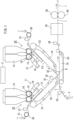
- FIG.1 is a schematic layout diagram showing an embodiment 1 of the manufacturing apparatus of the present invention.
- the stacking part is a stacking roller R that rolls in the first sheet S1 conveyed by the first conveyor C1 and the second sheet S2 conveyed by the second conveyor C2 and also stacks the first sheet S1 and the second sheet S2 on each other.
- first conveyor C1, the second conveyor C2, and the stacking roller R are arranged in such a manner that the upper surfaces of the first and second sheets S1 and S2 conveyed by the first conveyor C1, the second conveyor C2, and the stacking roller R form a V-shape valley.
- Another preferred apparatus further includes an introduction part 50 that introduces a liquid-permeable third sheet S3 to be interposed between the first sheet S1 and the second sheet S2 into the stacking roller R.
- the third sheet is provided between the two sheets.
- Another preferred apparatus further includes a controller C that selectively controls operation of at least one of a first unit U1 including the first conveyor C1 and the first distribution device 11 and a second unit U2 including the second conveyor C2 and the second distribution device 12.
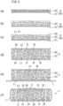
- FIG.3 is an enlarged cross-sectional view showing an absorbent body as well as its manufacturing steps.
- FIG.3 (f) shows an absorbent body 1 used as an absorbent core for a disposable diaper, for example.
- an absorbent body 1 includes: a first sheet S1 and a second sheet S2 each having granular powder 20; and a thin paper (tissue paper) T wrapping the first sheet S1 and the second sheet S2.
- the first and second sheets S1, S2 are not yet fluffed up (i.e., before raising).
- a spread layer 21 at the back side as a base and a short fiber layer 22 at the front side are stacked.
- the short fiber layer 22 is a non-woven fabric layer formed from short fiber, and is formed by the air blow process, for example. Such non-woven fabric layer may be formed by blowing hot air on lined-up short fiber.
- the spread layer 21 is thinner than the short fiber layer 22 and has higher density than the short fiber layer 22.
- the spread layer 21 allows liquid to permeate across an extensive area due to its high diffusibility in the planar direction.
- the first and second sheets S1, S2 are fluffed up.
- the first and second sheets S1, S2 transform from a state where the short fiber layer 22 lies (not fluffed-up) to a state where the short fiber layer 22 is raised to have small bulk density and to become thick.
- the short fiber layer 22 of the first and second sheet S1, S2 after raising is in a state where the granular powder 20 is sprinkled.
- the granular powder 20 is well-known superabsorbent polymer (SAP).
- SAP superabsorbent polymer
- the short fiber layer 22 holding the granular powder 20 configures a first absorbent layer L1 and a second absorbent layer L2.
- the first and second sheets S1, S2 including the granular powder 20 are stacked together such that the short fiber layers 22 of both sheets contact with each other with an adhesion layer 23 therebetween, thereby becoming one-sheet thick stack S.
- the first and second absorbent layers L1, L2 face and contact each other.
- the stack S is wrapped by the thin paper T, becoming a well-known absorbent body 1.
- FIG.1 and FIG.2 shows an embodiment 1.
- the present manufacturing apparatus includes a first unit U1, a second unit U2, a stacking roller R (one example of stacking part), and a controller C.
- the first and second units U1, U2 have a similar structure, and are arranged in reflection symmetry (plane symmetry).
- the first unit U1 includes a first conveyor C1 and a first distribution device 11.
- the second unit U2 includes a second conveyor C2 and a second distribution device 12.
- the controller C selectively controls at least one of the first and second units U1, U2.
- the first conveyor C1 conveys an air-permeable first sheet S1 along a flat first slope surface F1 while sucking the first sheet S1.
- the second conveyor C2 conveys an air-permeable second sheet S2 along a flat second slope surface F2 tilting opposite to the first slope surface F1 while sucking the second sheet S2.
- top surfaces (upper surfaces) of the first and second sheets S1, S2 are fluffed up (raised) in advance.
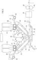
- the first distribution device 11 sprinkles absorbent granular powder on the upper surface of the first sheet S1 conveyed along the first slope surface F1, forming the first absorbent layer L1 in the short fiber layer 22 of the first sheet S1 of FIG.2 .
- the second distribution device 12 of FIG. 1 sprinkles absorbent granular powder on the upper surface of the second sheet S2 conveyed along the second slope surface F2, forming the second absorbent layer L2 in the short fiber layer 22 of the second sheet S2 of FIG.2 .
- the granular powder 20 gets into each short fiber layer (absorbent layer) 22 by negative pressure from a corresponding negative pressure case 19 while the first and second sheets S1, S2 are conveyed by the first and second conveyors C1, C2, respectively.
- the stacking roller R stacks the first and second sheets S1, S2 so that the first absorbent layer L1 of the first sheet S1 conveyed by the first conveyor C1 and the second absorbent layer L2 of the second sheet S2 conveyed by the second conveyor C2 face each other.
- the stacking roller R rolls in the first sheet S1 conveyed by the first conveyor C1 and the second sheet S2 conveyed by the second conveyor C2, and puts them together.
- the first conveyor C1, the second conveyor C2 and the stacking roller R are arranged so that the upper surfaces of the first and second sheets S1, S2 conveyed by the first conveyor C1, the second conveyor C2 and the stacking roller R of FIG.1 form a V-shaped valley.
- each conveyor C1, C2 of FIG.2 is provided with a negative pressure case 19 that sucks a corresponding sheet during conveyance to hold the granular powder 20 in the short fiber layer 22 of the sheet.
- the fluff-up roller 30 of FIG. 1 is a roller having a lot of teeth and rotates slower than the conveyance speed of the sheets S1, S2. With this speed difference, the fluff-up roller 30 raises (fluffs up) the short fiber layer 22 of the sheet of FIG.3 (a) as shown in FIG.3 (b) .
- the first applicator 31 for adhesive is provided between the fluff-up roller 30 and the conveyors C1, C2 of FIG.1 . Adhesive is applied to the front surface of the raised short fiber layer 22 ( FIG.3 (b) ).
- a first distribution device 11 and a second distribution device 12 sprinkle the granular powder 20 on the sheet.
- Each device includes a hopper 13 storing the granular powder 20, a meter 14, a guider 15 and a distribution case 16.
- the distribution case 16 is provided with a distribution mouth and a shutter for opening/closing the distribution mouth. With this configuration, a predetermined granular powder 20 is sprinkled intermittently on the short fiber layer 22 ( FIG.2 ) of the corresponding sheet.
- Feeding of sheets and sprinkling of the granular powder 20 are disclosed in WO2017/131014 , for example, and its disclosure is incorporated herein by reference.
- the second applicator 32 applies adhesive to the sheet S1 of the sheets, which the granular powder 20 is sprinkled.
- the short fiber layers 22 of the first and second sheets S1, S2 are joined together after the sheets S1, S2 are stacked by the stacking roller R.
- a thin paper T is fed on the stacking conveyor C3.
- the third applicator 33 is provided upstream of the stacking conveyor C3, and applies adhesive to the center area of the upper surface of the thin paper T.
- the stacking conveyor C3 conveys the sheet material downstream in a state where the thin paper T is provided under the stack S of the first and second sheets S1, S2 stacked together. In the conveyance, the stack S is joined to the front surface of the thin paper T. In the present embodiment, the stacking conveyor C3 contacts the stacking roller R with the stack S and the thin paper T therebetween.
- the fourth applicator 34, a folder 35 and a pair of pressure contact rollers 36 are provided downstream of the stacking conveyor C3 of FIG.1 .
- the stacking conveyor C3 includes a negative pressure case 19 sucking the thin paper T.
- the fourth applicator 34 applies adhesive to side edges of the upper surface of the thin paper T. Note that a width of the thin paper T is more than two times larger than that of the stack S.
- the folder 35 of FIG.1 folds the thin paper T as shown in FIG.3 (f) to wrap the stack S by the thin paper T, forming the absorbent body 1.
- the pressure contact roller 36 presses hard the absorbent body 1 in its thickness direction.
- the first sheet S1 and the second sheet S2 are fed to the corresponding fluff-up roller 30,30, and the short fiber layer 22 of FIG.3 (a) of each sheet is raised (fluffed up). Then, the first applicator 31 ( FIG.1 ) applies adhesive to the raised short fiber layer 22 of FIG.3 (b) . Thereafter, the first and second sheets S1, S2 of FIG.1 are conveyed toward the stacking roller R along the flat slope surface of the respective first and second conveyors C1, C2 while the sheets S1, S2 are sucked by the first and second conveyors C1, C2.
- Granular powder is sprinkled on the upper surfaces of the first and second sheets S1, S2 of FIG.1 along their flat slope surfaces.
- the first distribution device 11 and the second distribution device 12 sprinkle the granular powder 20 on the respective first and second sheet S1, S2, forming the first absorbent layer L1 and the second absorbent layer L2 ( FIG.3 (c) ) of FIG.2 including the granular powder 20.
- the sprinkled granular powder 20 is held in the short fiber layer 22 of the first and second sheets S1, S2, thereby the first and second absorbent layers L1, L2 formed.
- the granular powder 20 gets into the short fiber layer (absorbent layer) 22 of each first and second sheet S1, S2 by the negative pressure from the corresponding negative pressure case 19 while the first and second sheets S1, S2 are conveyed by the first and second conveyors C1, C2.
- first sheet S1 and the second sheet S2 are stacked together at the stacking roller R so that the first absorbent layer L1 and the second absorbent layer L2 face each other.
- first absorbent layer L1 of the first sheet S1 and the second absorbent layer L2 of the second sheet S2 are stacked in a state where they contact each other.
- the second applicator 32 applies adhesive to the first absorbent layer L1, and then the first absorbent layer L1 and the second absorbent layer L2 are pulled into the stacking roller R, forming the stack S of FIG.3 (d) .
- the stack S is arranged on the thin paper P conveyed by the stacking roller C3 of FIG.2 .
- the thin paper T is folded by the folder 35 of FIG.1 , and then the absorbent body 1 is pressed hard by the pressure contact roller 36, thereby the absorbent body 1 of FIG.3 (f) formed.
- the first absorbent layer L1 and the second absorbent layer L2 contact each other and they are sandwiched between the spread layers 21, 21.
- the present manufacturing apparatus is able to manufacture the absorbent body 1 of FIG.4 (b) and FIG.4 (c) in addition to the absorbent body 1 of FIG.4 (a) .
- the first unit U1 at the left side of FIG.1 is operated whereas the second unit U2 at the right side is stopped.
- an overlap part T1 of the thin paper T contacts the first absorbent layer L1, and the overlap part T1 and the spread layer 21 are arranged sandwiching the short fiber layer 22 (the first absorbent layer L1).
- the second unit U2 at the right side of FIG.1 is operated whereas the first unit U1 at the left side is stopped.
- the overlap part T1 of FIG.4 (c) of the thin paper T contacts the spread layer 21.
- the absorbent body 1 of FIG.4 (d) has a liquid-permeable third sheet S3 between the first sheet S1 and the second sheet S2.
- the absorbent body 1 is produced by the manufacturing apparatus of FIG.5 .
- this embodiment further includes an introduction roller 50 introducing the third sheet S3 into the stacking roller R.
- the third sheet S3 is introduced between the first sheet S1 and the second sheet S2.
- the third sheet S3 is a sheet having diffusibility as the spread layer 21 of the first and second sheets S1, S2.
- FIG.6 The manufacturing apparatus of FIG.6 is closely similar to that of the embodiment 1 in FIG.1 . Thus, different parts from the embodiment 1 are mainly explained.
- negative pressure cases 19 are provided with respective first and second conveyors C1, C2, and may be set to suck air in an area downstream from a point P1 around where the granular powder 20 ( FIG.2 ) drops. This arrangement prevents the granular powder 20 from scattered by air flow generated between each distribution device 11, 12 and the corresponding conveyor.
- scatter-prevention boards P, P may be provided on opposite sides of each conveyor C1, C2 so as to extend along the flow direction of the first and second conveyors C1, C2.
- the scatter-prevention board P prevents air flow from generated in directions other than the flow direction of the conveyors C1, C2, and thus is useful in preventing scatter of the granular powder 20.
- the stacking roller R may configure a part of the first conveyor C1 or the second conveyor C2.
- the lower-end roller of the second conveyor C2 configures the stacking roller R.
- the granular powder 20 may scatter near the stacking roller R.
- a small diameter of the stacking roller R as in FIG.6 it is likely to prevent scatter of the granular powder 20.
- the fluff-up roller will not need to be provided.
- the first unit U1 and the second unit U2 will be arranged in completely symmetry.
- the present invention is used in manufacturing various absorbent bodies like disposable underwear and diapers.
Landscapes
- Health & Medical Sciences (AREA)
- Engineering & Computer Science (AREA)
- Life Sciences & Earth Sciences (AREA)
- Biomedical Technology (AREA)
- Heart & Thoracic Surgery (AREA)
- Vascular Medicine (AREA)
- Epidemiology (AREA)
- Animal Behavior & Ethology (AREA)
- General Health & Medical Sciences (AREA)
- Public Health (AREA)
- Veterinary Medicine (AREA)
- Manufacturing & Machinery (AREA)
- Absorbent Articles And Supports Therefor (AREA)
Applications Claiming Priority (2)
| Application Number | Priority Date | Filing Date | Title |
|---|---|---|---|
| JP2019135217 | 2019-07-23 | ||
| PCT/JP2020/026979 WO2021015001A1 (ja) | 2019-07-23 | 2020-07-10 | 吸収体の製造装置および製造方法 |
Publications (4)
| Publication Number | Publication Date |
|---|---|
| EP4005543A1 EP4005543A1 (en) | 2022-06-01 |
| EP4005543A4 EP4005543A4 (en) | 2022-08-24 |
| EP4005543B1 true EP4005543B1 (en) | 2024-12-04 |
| EP4005543C0 EP4005543C0 (en) | 2024-12-04 |
Family
ID=74193898
Family Applications (1)
| Application Number | Title | Priority Date | Filing Date |
|---|---|---|---|
| EP20842953.0A Active EP4005543B1 (en) | 2019-07-23 | 2020-07-10 | Manufacturing device and manufacturing method of absorber |
Country Status (5)
| Country | Link |
|---|---|
| US (1) | US12403045B2 (https=) |
| EP (1) | EP4005543B1 (https=) |
| JP (1) | JP7266773B2 (https=) |
| CN (1) | CN113993490A (https=) |
| WO (1) | WO2021015001A1 (https=) |
Families Citing this family (1)
| Publication number | Priority date | Publication date | Assignee | Title |
|---|---|---|---|---|
| EP4483852B1 (en) | 2022-03-28 | 2026-05-06 | Zuiko Corporation | Method for manufacturing absorbent body |
Family Cites Families (11)
| Publication number | Priority date | Publication date | Assignee | Title |
|---|---|---|---|---|
| JP3167920B2 (ja) * | 1996-04-01 | 2001-05-21 | トーヨー衛材株式会社 | 吸水体およびその製造方法 |
| US7759540B2 (en) | 2002-07-23 | 2010-07-20 | Paragon Trade Brands, Llc | Absorbent articles containing absorbent cores having zoned absorbency and methods of making same |
| JP6170308B2 (ja) * | 2013-02-13 | 2017-07-26 | 花王株式会社 | 吸収体の製造装置 |
| EP2905000B1 (en) | 2014-02-11 | 2016-12-28 | The Procter and Gamble Company | Method and apparatus for making an absorbent structure comprising channels |
| EP3037079B1 (en) * | 2014-12-23 | 2018-07-25 | The Procter and Gamble Company | Absorbent core comprising a high loft central layer and channels |
| ITUB20154187A1 (it) * | 2015-10-06 | 2016-01-06 | Fameccanica Data Spa | Procedimento ed apparecchiatura per la produzione di una struttura assorbente |
| CN108699747B (zh) * | 2016-01-27 | 2021-03-02 | 株式会社瑞光 | 含颗粒体物品的制造装置以及含颗粒体物品的制造方法 |
| CN108236542B (zh) * | 2016-12-27 | 2023-03-10 | 大王制纸株式会社 | 吸收性物品的制造方法和吸收性物品 |
| JP6356298B1 (ja) | 2017-03-30 | 2018-07-11 | 大王製紙株式会社 | 粉粒体の散布装置および散布方法 |
| CN114159232A (zh) * | 2017-08-04 | 2022-03-11 | 株式会社瑞光 | 吸收体的制造方法、吸收体的制造装置以及吸收体 |
| JP3218416U (ja) * | 2018-08-02 | 2018-10-11 | ユニチカ株式会社 | 吸収性物品のためのトップシート |
-
2020
- 2020-07-10 EP EP20842953.0A patent/EP4005543B1/en active Active
- 2020-07-10 JP JP2021533941A patent/JP7266773B2/ja active Active
- 2020-07-10 US US17/625,117 patent/US12403045B2/en active Active
- 2020-07-10 WO PCT/JP2020/026979 patent/WO2021015001A1/ja not_active Ceased
- 2020-07-10 CN CN202080045131.5A patent/CN113993490A/zh active Pending
Also Published As
| Publication number | Publication date |
|---|---|
| CN113993490A (zh) | 2022-01-28 |
| WO2021015001A1 (ja) | 2021-01-28 |
| US20220265483A1 (en) | 2022-08-25 |
| EP4005543C0 (en) | 2024-12-04 |
| EP4005543A1 (en) | 2022-06-01 |
| US12403045B2 (en) | 2025-09-02 |
| JPWO2021015001A1 (https=) | 2021-01-28 |
| EP4005543A4 (en) | 2022-08-24 |
| JP7266773B2 (ja) | 2023-05-01 |
Similar Documents
| Publication | Publication Date | Title |
|---|---|---|
| US8696343B2 (en) | Folding apparatus | |
| CN1300582A (zh) | 制造颗粒沉积体的方法 | |
| US10828204B2 (en) | Apparatus and method for forming absorbent cores | |
| US20120056347A1 (en) | Manufacturing method and a manufacturing apparatus for a composite sheet | |
| RU2744188C1 (ru) | Упаковка впитывающего изделия и способ изготовления упаковки впитывающего изделия | |
| CN102665626A (zh) | 吸收体的制造方法和制造装置 | |
| EP2730261A1 (en) | Apparatus and methods for forming laminates containing additive matter | |
| JP4903865B2 (ja) | エアレイド吸収コアを形成するための装置および方法 | |
| CN111093575B (zh) | 吸收体的制造方法、吸收体的制造装置以及吸收体 | |
| CN103561701B (zh) | 用于制造吸收性卫生用品填料段的方法和单元 | |
| CN104812347B (zh) | 吸收性物品的吸收体的制造装置和制造方法 | |
| CN102348442A (zh) | 用于制造个人卫生用品的制造机器 | |
| EP4005543B1 (en) | Manufacturing device and manufacturing method of absorber | |
| JP5475434B2 (ja) | 吸収体の製造方法及び製造装置 | |
| CN114269305B (zh) | 吸收体的制造装置以及方法 | |
| JP2018117866A (ja) | 吸収性物品 | |
| JP2019063375A (ja) | 吸収性物品の製造方法及び吸収性物品の製造装置 | |
| US20170079848A1 (en) | Method for making absorbent articles | |
| JP7320484B2 (ja) | 吸収体の製造方法 | |
| CN110916905B (zh) | 用于形成吸收性物品的方法和单元 | |
| JP4786745B2 (ja) | エアレイド物品を製造する装置 | |
| CN121038755A (zh) | 吸收体的制造装置及制造方法 | |
| RU2405516C2 (ru) | Устройство и способ формирования получаемых пневмоукладкой абсорбирующих сердцевин | |
| RU2415658C2 (ru) | Устройство и способ для формования пневмоуложенных абсорбирующих сердцевин | |
| JP2018102772A (ja) | 吸収性物品の製造方法及び製造装置 |
Legal Events
| Date | Code | Title | Description |
|---|---|---|---|
| STAA | Information on the status of an ep patent application or granted ep patent |
Free format text: STATUS: THE INTERNATIONAL PUBLICATION HAS BEEN MADE |
|
| PUAI | Public reference made under article 153(3) epc to a published international application that has entered the european phase |
Free format text: ORIGINAL CODE: 0009012 |
|
| STAA | Information on the status of an ep patent application or granted ep patent |
Free format text: STATUS: REQUEST FOR EXAMINATION WAS MADE |
|
| 17P | Request for examination filed |
Effective date: 20220113 |
|
| AK | Designated contracting states |
Kind code of ref document: A1 Designated state(s): AL AT BE BG CH CY CZ DE DK EE ES FI FR GB GR HR HU IE IS IT LI LT LU LV MC MK MT NL NO PL PT RO RS SE SI SK SM TR |
|
| A4 | Supplementary search report drawn up and despatched |
Effective date: 20220722 |
|
| RIC1 | Information provided on ipc code assigned before grant |
Ipc: A61F 13/537 20060101ALI20220718BHEP Ipc: A61F 13/534 20060101ALI20220718BHEP Ipc: A61F 13/15 20060101AFI20220718BHEP |
|
| DAV | Request for validation of the european patent (deleted) | ||
| DAX | Request for extension of the european patent (deleted) | ||
| STAA | Information on the status of an ep patent application or granted ep patent |
Free format text: STATUS: EXAMINATION IS IN PROGRESS |
|
| 17Q | First examination report despatched |
Effective date: 20230921 |
|
| GRAP | Despatch of communication of intention to grant a patent |
Free format text: ORIGINAL CODE: EPIDOSNIGR1 |
|
| STAA | Information on the status of an ep patent application or granted ep patent |
Free format text: STATUS: GRANT OF PATENT IS INTENDED |
|
| INTG | Intention to grant announced |
Effective date: 20240704 |
|
| GRAS | Grant fee paid |
Free format text: ORIGINAL CODE: EPIDOSNIGR3 |
|
| GRAA | (expected) grant |
Free format text: ORIGINAL CODE: 0009210 |
|
| STAA | Information on the status of an ep patent application or granted ep patent |
Free format text: STATUS: THE PATENT HAS BEEN GRANTED |
|
| AK | Designated contracting states |
Kind code of ref document: B1 Designated state(s): AL AT BE BG CH CY CZ DE DK EE ES FI FR GB GR HR HU IE IS IT LI LT LU LV MC MK MT NL NO PL PT RO RS SE SI SK SM TR |
|
| REG | Reference to a national code |
Ref country code: CH Ref legal event code: EP |
|
| REG | Reference to a national code |
Ref country code: DE Ref legal event code: R096 Ref document number: 602020042688 Country of ref document: DE |
|
| REG | Reference to a national code |
Ref country code: IE Ref legal event code: FG4D |
|
| U01 | Request for unitary effect filed |
Effective date: 20241220 |
|
| U07 | Unitary effect registered |
Designated state(s): AT BE BG DE DK EE FI FR IT LT LU LV MT NL PT RO SE SI Effective date: 20250113 |
|
| PG25 | Lapsed in a contracting state [announced via postgrant information from national office to epo] |
Ref country code: HR Free format text: LAPSE BECAUSE OF FAILURE TO SUBMIT A TRANSLATION OF THE DESCRIPTION OR TO PAY THE FEE WITHIN THE PRESCRIBED TIME-LIMIT Effective date: 20241204 |
|
| PG25 | Lapsed in a contracting state [announced via postgrant information from national office to epo] |
Ref country code: ES Free format text: LAPSE BECAUSE OF FAILURE TO SUBMIT A TRANSLATION OF THE DESCRIPTION OR TO PAY THE FEE WITHIN THE PRESCRIBED TIME-LIMIT Effective date: 20241204 |
|
| PG25 | Lapsed in a contracting state [announced via postgrant information from national office to epo] |
Ref country code: NO Free format text: LAPSE BECAUSE OF FAILURE TO SUBMIT A TRANSLATION OF THE DESCRIPTION OR TO PAY THE FEE WITHIN THE PRESCRIBED TIME-LIMIT Effective date: 20250304 |
|
| PG25 | Lapsed in a contracting state [announced via postgrant information from national office to epo] |
Ref country code: GR Free format text: LAPSE BECAUSE OF FAILURE TO SUBMIT A TRANSLATION OF THE DESCRIPTION OR TO PAY THE FEE WITHIN THE PRESCRIBED TIME-LIMIT Effective date: 20250305 |
|
| PG25 | Lapsed in a contracting state [announced via postgrant information from national office to epo] |
Ref country code: RS Free format text: LAPSE BECAUSE OF FAILURE TO SUBMIT A TRANSLATION OF THE DESCRIPTION OR TO PAY THE FEE WITHIN THE PRESCRIBED TIME-LIMIT Effective date: 20250304 |
|
| PG25 | Lapsed in a contracting state [announced via postgrant information from national office to epo] |
Ref country code: SM Free format text: LAPSE BECAUSE OF FAILURE TO SUBMIT A TRANSLATION OF THE DESCRIPTION OR TO PAY THE FEE WITHIN THE PRESCRIBED TIME-LIMIT Effective date: 20241204 |
|
| PG25 | Lapsed in a contracting state [announced via postgrant information from national office to epo] |
Ref country code: PL Free format text: LAPSE BECAUSE OF FAILURE TO SUBMIT A TRANSLATION OF THE DESCRIPTION OR TO PAY THE FEE WITHIN THE PRESCRIBED TIME-LIMIT Effective date: 20241204 |
|
| PG25 | Lapsed in a contracting state [announced via postgrant information from national office to epo] |
Ref country code: IS Free format text: LAPSE BECAUSE OF FAILURE TO SUBMIT A TRANSLATION OF THE DESCRIPTION OR TO PAY THE FEE WITHIN THE PRESCRIBED TIME-LIMIT Effective date: 20250404 |
|
| PG25 | Lapsed in a contracting state [announced via postgrant information from national office to epo] |
Ref country code: SK Free format text: LAPSE BECAUSE OF FAILURE TO SUBMIT A TRANSLATION OF THE DESCRIPTION OR TO PAY THE FEE WITHIN THE PRESCRIBED TIME-LIMIT Effective date: 20241204 |
|
| PG25 | Lapsed in a contracting state [announced via postgrant information from national office to epo] |
Ref country code: CZ Free format text: LAPSE BECAUSE OF FAILURE TO SUBMIT A TRANSLATION OF THE DESCRIPTION OR TO PAY THE FEE WITHIN THE PRESCRIBED TIME-LIMIT Effective date: 20241204 |
|
| U20 | Renewal fee for the european patent with unitary effect paid |
Year of fee payment: 6 Effective date: 20250728 |
|
| PLBE | No opposition filed within time limit |
Free format text: ORIGINAL CODE: 0009261 |
|
| STAA | Information on the status of an ep patent application or granted ep patent |
Free format text: STATUS: NO OPPOSITION FILED WITHIN TIME LIMIT |
|
| REG | Reference to a national code |
Ref country code: CH Ref legal event code: L10 Free format text: ST27 STATUS EVENT CODE: U-0-0-L10-L00 (AS PROVIDED BY THE NATIONAL OFFICE) Effective date: 20251015 |
|
| 26N | No opposition filed |
Effective date: 20250905 |
|
| REG | Reference to a national code |
Ref country code: CH Ref legal event code: H13 Free format text: ST27 STATUS EVENT CODE: U-0-0-H10-H13 (AS PROVIDED BY THE NATIONAL OFFICE) Effective date: 20260224 |
|
| GBPC | Gb: european patent ceased through non-payment of renewal fee |
Effective date: 20250710 |
|
| PG25 | Lapsed in a contracting state [announced via postgrant information from national office to epo] |
Ref country code: GB Free format text: LAPSE BECAUSE OF NON-PAYMENT OF DUE FEES Effective date: 20250710 |
|
| PG25 | Lapsed in a contracting state [announced via postgrant information from national office to epo] |
Ref country code: CH Free format text: LAPSE BECAUSE OF NON-PAYMENT OF DUE FEES Effective date: 20250731 |