EP4002016B1 - Armbanduhr mit mechanischem uhrwerk mit kraftsteuerungsmechanismus - Google Patents
Armbanduhr mit mechanischem uhrwerk mit kraftsteuerungsmechanismus Download PDFInfo
- Publication number
- EP4002016B1 EP4002016B1 EP20208925.6A EP20208925A EP4002016B1 EP 4002016 B1 EP4002016 B1 EP 4002016B1 EP 20208925 A EP20208925 A EP 20208925A EP 4002016 B1 EP4002016 B1 EP 4002016B1
- Authority
- EP
- European Patent Office
- Prior art keywords
- wheel
- watch
- seconds
- mechanical movement
- fixed
- Prior art date
- Legal status (The legal status is an assumption and is not a legal conclusion. Google has not performed a legal analysis and makes no representation as to the accuracy of the status listed.)
- Active
Links
Images


Classifications
-
- G—PHYSICS
- G04—HOROLOGY
- G04B—MECHANICALLY-DRIVEN CLOCKS OR WATCHES; MECHANICAL PARTS OF CLOCKS OR WATCHES IN GENERAL; TIME PIECES USING THE POSITION OF THE SUN, MOON OR STARS
- G04B15/00—Escapements
-
- G—PHYSICS
- G04—HOROLOGY
- G04B—MECHANICALLY-DRIVEN CLOCKS OR WATCHES; MECHANICAL PARTS OF CLOCKS OR WATCHES IN GENERAL; TIME PIECES USING THE POSITION OF THE SUN, MOON OR STARS
- G04B19/00—Indicating the time by visual means
- G04B19/24—Clocks or watches with date or week-day indicators, i.e. calendar clocks or watches; Clockwork calendars
- G04B19/243—Clocks or watches with date or week-day indicators, i.e. calendar clocks or watches; Clockwork calendars characterised by the shape of the date indicator
- G04B19/257—Clocks or watches with date or week-day indicators, i.e. calendar clocks or watches; Clockwork calendars characterised by the shape of the date indicator drum-shaped or three-dimensional shaped
- G04B19/2573—Driving or releasing mechanisms wherein the date indicators are driven or released mechanically by a clockwork movement
- G04B19/2575—Driving or releasing mechanisms wherein the date indicators are driven or released mechanically by a clockwork movement driven or released stepwise by the clockwork movement
-
- G—PHYSICS
- G04—HOROLOGY
- G04B—MECHANICALLY-DRIVEN CLOCKS OR WATCHES; MECHANICAL PARTS OF CLOCKS OR WATCHES IN GENERAL; TIME PIECES USING THE POSITION OF THE SUN, MOON OR STARS
- G04B15/00—Escapements
- G04B15/06—Free escapements
- G04B15/08—Lever escapements
-
- G—PHYSICS
- G04—HOROLOGY
- G04B—MECHANICALLY-DRIVEN CLOCKS OR WATCHES; MECHANICAL PARTS OF CLOCKS OR WATCHES IN GENERAL; TIME PIECES USING THE POSITION OF THE SUN, MOON OR STARS
- G04B13/00—Gearwork
- G04B13/002—Gearwork where rotation in one direction is changed into a stepping movement
-
- G—PHYSICS
- G04—HOROLOGY
- G04B—MECHANICALLY-DRIVEN CLOCKS OR WATCHES; MECHANICAL PARTS OF CLOCKS OR WATCHES IN GENERAL; TIME PIECES USING THE POSITION OF THE SUN, MOON OR STARS
- G04B13/00—Gearwork
- G04B13/02—Wheels; Pinions; Spindles; Pivots
-
- G—PHYSICS
- G04—HOROLOGY
- G04B—MECHANICALLY-DRIVEN CLOCKS OR WATCHES; MECHANICAL PARTS OF CLOCKS OR WATCHES IN GENERAL; TIME PIECES USING THE POSITION OF THE SUN, MOON OR STARS
- G04B15/00—Escapements
- G04B15/14—Component parts or constructional details, e.g. construction of the lever or the escape wheel
-
- G—PHYSICS
- G04—HOROLOGY
- G04B—MECHANICALLY-DRIVEN CLOCKS OR WATCHES; MECHANICAL PARTS OF CLOCKS OR WATCHES IN GENERAL; TIME PIECES USING THE POSITION OF THE SUN, MOON OR STARS
- G04B17/00—Mechanisms for stabilising frequency
- G04B17/20—Compensation of mechanisms for stabilising frequency
- G04B17/28—Compensation of mechanisms for stabilising frequency for the effect of imbalance of the weights, e.g. tourbillon
- G04B17/285—Tourbillons or carrousels
-
- G—PHYSICS
- G04—HOROLOGY
- G04B—MECHANICALLY-DRIVEN CLOCKS OR WATCHES; MECHANICAL PARTS OF CLOCKS OR WATCHES IN GENERAL; TIME PIECES USING THE POSITION OF THE SUN, MOON OR STARS
- G04B19/00—Indicating the time by visual means
- G04B19/02—Back-gearing arrangements between gear train and hands
Definitions
- the invention relates to a mechanical movement watch with a force control mechanism, such as the force due to gravity when wearing the watch and of the jumping second type.
- the force control mechanism may be a tourbillon mechanism mounted at the escapement.
- the tourbillon cage surrounds the escapement mechanism and preferably the cage makes a complete rotation every minute with in particular 60 jumps of a second made.
- a tourbillon also called a "rotating cage”
- a tourbillon is a watch complication, added to the escapement mechanism, intended to improve the precision of mechanical watches by counterbalancing the disturbances of the isochronism of the resonator due to the Earth's gravity.
- the fundamental criterion which marks a tourbillon, in comparison with a carousel in particular, is the presence of a fixed gear train on which the tourbillon cage meshes.
- the tourbillon cage is rotatably mounted between two fixing points.
- Gravity is also taken into account to compensate for any disturbances in the isochronism of the resonator.
- the escapement is coupled to the resonator. It interacts with it once or twice per oscillation period.
- the angle traveled by the resonator during the interaction is called the lift angle.
- the rest of the resonator's path is called the additional angle or arc.
- the resonator can be in contact with the escapement (rubbing rest escapement) or without contact (free escapement).
- the escapement performs two main phases, which are the release (or counting) and the impulse (or maintenance).
- the jumping second is intended to display the second in steps of a whole second, which corresponds on a 60-second dial to 6° of angle per second.
- This jumping second is often associated with constant force mechanisms that take advantage of the particular construction of this jumping second.
- Dead second or fixed second mechanisms also approach these constructions with the particularity of being able to stop the second at will like a chronograph.
- a mechanism for periodically jumping forward a pivoting cage carrying a wheel and an escapement pinion and an anchor cooperating with the wheel and a balance spring.
- it comprises retaining means for authorizing or prohibiting the pivoting of said cage depending on the movements or not.
- stopping means for authorizing or prohibiting the pivoting of the retaining means depending on their angular position.
- a constant force device periodically makes the retaining means cooperate. This device comprises a whip designed to perform complete revolutions.
- Some of these mechanisms can become desynchronized after complete disarming, and go into a blocking position. This requires a stop system linked to a power reserve mechanism, which will stop the mechanism before complete disarming.
- a constant force device for a watch, with dead seconds.
- This device makes it possible to move an axis of a mobile on a lever controlled by an energy storage spring, which tends to pivot the lever.
- the device comprises a pinion of a first seconds wheel of the movement, which meshes with a setting wheel pivotally mounted on this lever, and which meshes with the pinion of a second seconds wheel defining the mobile.
- the lever carrying a finger must adapt to cooperate with a ratchet toothing of a stop wheel, which meshes with the first seconds wheel.
- the gear train is blocked, in particular composed of the first seconds wheel and the setting wheel without force transmission of the first seconds wheel and the setting wheel.
- the second seconds wheel is controlled by the escapement and only turns when the latter is moved by the balance wheel.
- the spring is wound by moving the lever in the opposite direction, for which the spring exerts a torque on the lever that is lower than that exerted by the barrel spring on the lever, when the stop wheel is released.
- the utility model CN 209014916 U describes a tourbillon clock mechanism having a toothed wheel.
- the toothed wheel is composed of a central portion for the passage of an axis, connected by spring-type metal coils to an inner wall of a crown with external peripheral teeth.
- THE patent EP 3 356 690 B1 describes a watch component having a flexible pivot of the well-known separate crossed blade type, and having means for adjusting the position of the crossing point of the blades.
- WO 2018/193365 A1 depicted in Figure 8 is a timepiece with a force control mechanism comprising a jumping second wheel and a rotating locking device.
- the invention therefore aims to overcome the drawbacks of the state of the art by providing a watch with a mechanical movement with a force compensation or control mechanism of the jumping second type, overcoming the drawbacks of the aforementioned prior art devices.
- the invention relates to a watch with a mechanical movement with a force compensation or control mechanism of the second type. jumping, which includes the features defined in independent claim 1.
- An advantage of the mechanical movement watch with a force control mechanism lies in the fact that it comprises a second wheel for accumulating the energy necessary to maintain several oscillations of the escapement mechanism with the oscillator, in particular in a stop mode before switching to a jump mode.
- the second wheel maintains a few oscillations of the resonator or oscillator without part of the gear train coming from the barrel being driven.
- the second wheel releases a blocking element, such as a whip after a certain number of oscillations to move in particular the tourbillon cage by 6° in the clockwise direction (SAM) and the finishing gear train coming from the barrel defining a second wheel of the jumping second type.
- the whip is released and by it, the intermediate wheel linked to the whip, the medium wheel, the large medium wheel and the barrel to drive the tourbillon cage by a step of 6° in a direction opposite to the accumulation of the second wheel.
- the tourbillon cage can be moved angularly after a certain number of oscillations defining a second.
- the second wheel is intended to move in the stop phase by a certain number of small steps following the oscillations of the spiral spring of the oscillator linked to the escapement mechanism, which is of the Swiss anchor type.
- the second wheel In this stop phase or stop mode, the second wheel second rotates counterclockwise while being rotated by a flexible guide with elastic blades, which is pre-wound.
- a movable portion of this flexible guide is fixed on a face of the second wheel, while a fixed portion of this flexible guide is fixed on a support of the watch movement, such as a plate.
- the movable portion of this flexible guide is preferably fixed directly below the second wheel.
- the flexible guide is mounted by an axial opening, coaxially with a second pinion, which is the second and tourbillon pinion.
- the flexible guide with elastic blades comprises several elastic blades in series connecting more massive parts including the mobile and fixed portions of the flexible guide, and possibly other intermediate portions.
- the flexible guide with elastic blades in series can thus be produced with a more robust structure capable of ensuring the rotation of the second wheel with a return torque advantageously used to replace the spring of the force control mechanism and with better axial support.
- such a flexible guide with elastic blades makes it possible to have an absence of friction, wear and energy dissipation, as well as an absence of play and precise guidance.
- the watch with a mechanical movement with a force control mechanism and of the jumping second type can be with a tourbillon whose cage encloses an oscillator and an escapement mechanism as explained below, or according to a traditional mechanical movement without a tourbillon, which will be explained later with reference to the figure 4 .
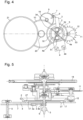
- FIGS. 1 and 2 represent a part of a mechanical watch movement 1 which is shown without the energy source, such as the barrel which is the mainspring and which is connected, in this case, to a fusee connected by a chain to the barrel drum for its drive. Also not shown is a large medium wheel, which is driven in rotation by a toothing on the periphery of the spindle according to a traditional embodiment. This energy is applied in the form of a torque to the pinion of the middle wheel 10.
- FIGS. 1 and 2 therefore represent a part of a mechanical watch movement comprising a finishing gear train 5, 8, 9, 10 in which is arranged a force control mechanism of the mechanical watch movement 1.
- This force control mechanism may be similar to a constant force device.
- the finishing gear train is arranged between a source of energy not shown, which is preferably a spring barrel, and an escapement mechanism for example with a Swiss lever 13 and having an escape wheel 11 in the form of a wheel, alternately retained and released by an oscillator 14, which is preferably a balance spring and the energy for maintaining its oscillation is provided by said escape wheel 11.
- the escape wheel 11 is arranged to be able to rotate in the same direction of rotation at each half-oscillation of the oscillator 14.
- the escape wheel 11 meshes with a second wheel 2 which is hereinafter also defined as a fixed second wheel SFA.
- This second wheel 2 is called a fixed second wheel SFA, even if it is not fixed in its operation.
- This fixed second wheel SFA 2 can rotate counterclockwise (SIAM) to maintain the operation of the escapement mechanism linked to the oscillator in a stop mode, and rotate clockwise (SAM) in a jump mode to perform a jump corresponding to 1 second.
- SIAM counterclockwise
- SAM clockwise
- the fixed second wheel SFA 2 preferably has peripheral teeth meshing with a toothed escape pinion 12 coaxial with said escape wheel 11.
- the fixed second wheel SFA 2 rotates counterclockwise (SIAM) by the restoring force of the flexible guide 4 and drives the escape wheel 11 at each half-oscillation of the oscillator 14 via the escapement toothed pinion 12 so as to maintain the operation of the oscillator and the escapement mechanism in this stopping phase.
- SIAM counterclockwise
- the fixed seconds wheel SFA 2 pivots in SIAM on its flexible guide 4 around the tourbillon cage 15 without touching the latter, which is stopped.
- This SIAM pivoting of the SFA 2 is carried out until the moment of the release of the finishing gear train 5, 8, 9, 10 by which a jump of one second is carried out by the tourbillon cage 15 and its second pinion 5, driving with it the fixed seconds wheel SFA 2, which is connected to the escapement wheel set 11, in the clockwise jump phase SAM.
- the force control mechanism comprises on the one hand a rotary blocking element 7 arranged to cooperate with a stop member 3 in connection with the fixed second wheel SFA 2 in the stop mode.
- this stop member 3 may be a rack 3, rotatably mounted at a first end of the rack 3 around an axis 33 arranged for example between a movement mounting plate and a middle bridge not shown.
- a second free end of the rack 3 comprises in a blocking part, a finger-shaped edge portion 3b freely arranged inside a guide housing between two teeth of a cam 6.
- the cam 6 is fixed integrally with said fixed second wheel SFA 2 near its center so as to rotate the rack 3 in each direction.
- the second free end of the rack 3 further comprises a stop piece 3a, such as a pallet 3a, arranged on a side opposite the edge portion 3b and arranged to block the rotary blocking element 7 in a stopping mode.
- the pallet 3a can be made of a hard material reducing friction with the locking element 7 in contact of the pallet 3a in a stopping phase.
- This stopping part which is the pallet 3a, can be made of a friction-reducing material such as ruby.
- a flexible guide 4 with elastic blades 4a or spring blades, which is pre-wound, is connected directly to the fixed second wheel SFA 2.
- the flexible guide 4 acts as a spring on the fixed second wheel SFA 2.
- the flexible guide 4 comprises a movable portion 4c with at least one opening 17 but preferably two openings 17 for fixing on a face of the fixed second wheel SFA 2.
- the flexible guide 4 is fixed on a lower face of the fixed second wheel SFA 2.
- elastic blades 4a are defined, these blades can be of rectangular, hexagonal or even round cross section. These elastic blades have a geometry: length and section which must be well determined to ensure the spring function to drive the fixed second wheel SFA 2 in rotation with the necessary torque. We can refer to the work W. H. Wittrick indicated below, for the production of flexible guides 4 with elastic blades 4a.
- At least one fixing means 27 in or through the opening(s) 17 is thus provided to fix the fixed second wheel SFA 2 on the movable portion 4c of the flexible guide 4.
- this fixing means 27 can be at least one material extension of the fixed second wheel SFA 2 to form a single piece with the wheel.
- Two material extensions 27 can be provided to be inserted for example by force respectively into the two openings 17 of the movable portion 4c of the flexible guide 4 to ensure good support and without protruding from each opening 17.
- a border can also be provided around each material extension 27 and can come directly from the material with the corresponding material extension to ensure a space between the lower face of the fixed second wheel SFA 2 and an upper face of the flexible guide 4.
- the flexible guide 4 further comprises a fixed portion 4b with at least one opening 16, but preferably two openings 16 to be mounted and fixed by means of a screw and nut assembly not shown on a support of the watch movement, such as a plate.
- a screw and nut assembly not shown on a support of the watch movement, such as a plate.
- Several elastic blades 4a or portions of elastic blades connect the mobile portion 4c to the fixed portion 4b as well as intermediate portions possibly between the mobile 4c and fixed 4b portions.
- the flexible guide 4 is mounted by an axial opening, coaxially with the second pinion 5, and around an axial tube of the fixed second wheel SFA 2 coaxial with the axis of the second pinion 5.
- the fixing means may also be a screw and nut assembly passing through openings in the movable portion and the fixed second wheel SFA 2, but with this type of assembly, too much space is wasted.
- the fixing of the fixed portion 4b of the flexible guide 4 on the plate can be carried out by a means other than the screw and nut assembly, taking as an example the fixing of the fixed second wheel SFA 2 on the flexible guide 4.
- the elastic blades 4a of the flexible guide 4 In the rest position, that is to say as soon as the jump mode is switched to the stop mode, the elastic blades 4a of the flexible guide 4 must be pre-stressed to accumulate mechanical energy to rotate the fixed second wheel SFA 2 in particular in the counterclockwise direction (SIAM).
- the rotation of the fixed second wheel SFA 2 also drives the escapement wheel 11 via an escapement pinion 12 coaxial with the escapement wheel of the Swiss lever escapement mechanism 13. This is advantageous for keeping the escapement mechanism with the oscillator 14 in operation in this stopping phase by the mechanical energy stored in the flexible guide 4 with elastic blades 4a. acting on the fixed second wheel SFA 2 to make it rotate in a counterclockwise direction (SIAM).
- SIAM counterclockwise direction
- the rack 3 is connected without the action of a spring to a cam 6 fixed on the fixed second wheel SFA 2 to block or release said finishing gear train according to the angular position of said fixed second wheel SFA 2 by retaining a whip 7, as a blocking element.
- This whip 7 comes into contact with a stop piece 3a of the blocking part of the rack 3.
- This stop piece is a pallet 3a, as described above.
- the fixed second wheel SFA 2 can rotate by 5 small steps corresponding to 6° of angle representing 1 second in the opposite direction.
- the whip 7 is itself driven by the going train and retained by the stop piece 3a. Once released at the end of the stopping phase, the rotation of the rack 3 releases the whip 7 which triggers the jump phase.
- the whip 7 performs a rotation corresponding to a jump of 1 second, driven by the going train, in the case shown, a half-turn.
- the finishing gear train similarly drives the tourbillon cage 15 via the second pinion 5 and the fixed second wheel SFA 2 in a clockwise direction (SAM), which resets the flexible guide 4.
- SAM clockwise direction
- This flexible guide 4 of the fixed second wheel SFA 2 is arranged to accumulate energy when said fixed second wheel SFA 2 is driven in SAM during the jump phase and to restore it to said fixed second wheel SFA 2 in SIAM during the stop phase.
- the frequency of the oscillator 14 is typically higher than 1 Hz and, for example, in this case, can be set to 2.5 Hz. Since the fixed seconds wheel SFA 2 rotates in the stopping phase with each small step corresponding to a half-oscillation (alternation), 5 half-oscillations of the oscillator 14 can be counted in the stopping phase until the moment of the release of the rotary blocking element 7 for the jump phase.
- the flexible guide 4 connected to the fixed seconds wheel SFA 2 must therefore provide energy during the 5 half-oscillations of the oscillator 14 or the cage is stopped, and be rearmed during the jump of said cage 15.
- the flexible guide 4 shown in the figure 2 comprises a fixed portion 4b arranged in a wide V-shaped opening housing of the movable portion 4c, which comprises an axial opening, which is coaxial with the axis of the second pinion 5.
- Two through openings 16 are provided in the fixed portion 4b and arranged on a single line with the axial opening.
- Two through openings 17 are provided in the movable portion 4c and arranged substantially on a single line with the axial opening.
- five successive elastic blades 4a connect a first inner side of the movable portion 4c to a first inner side of the fixed portion 4b.
- a first elastic blade 4a from the movable portion 4c is connected to a first intermediate central portion.
- a second elastic blade 4a from the first intermediate central portion is connected to a first intermediate peripheral portion.
- a third elastic blade 4a from the first intermediate peripheral portion is connected to a second intermediate central portion.
- a fourth elastic blade 4a from the second intermediate central portion is connected to a second intermediate peripheral portion.
- a fifth elastic blade from the second intermediate peripheral portion is connected to a first inner side of the fixed portion 4b.
- Five successive elastic blades 4a connect a second inner side of the movable portion 4c to a second inner side of the fixed portion 4b.
- a second elastic blade 4a from the movable portion 4c is connected to the same first intermediate central portion.
- a second elastic blade 4a from the same first intermediate central portion is connected to the same first intermediate peripheral portion.
- a third elastic blade 4a from the first intermediate peripheral portion is connected to the same second intermediate central portion.
- a fourth elastic blade 4a from the second intermediate central portion is connected to the same second intermediate peripheral portion.
- a fifth elastic blade from the second intermediate peripheral portion is connected to a first inner side of the fixed portion 4b.
- the fixed part 4b is arranged inside between the movable portion 4c and the two intermediate peripheral portions.
- the two intermediate central portions form an arc of a circle centered on the axis of the second pinion 5, and the same is true for the two intermediate peripheral portions also centered on the axis of the second pinion 5.
- half-oscillations of the oscillator 14 may be provided in the stop phase depending on the oscillation frequency of the oscillator 14.
- Each half-oscillation must be equal to 0.2 s for a 2.5 Hz oscillator.
- the number of small steps made by the fixed second wheel SFA 2 in the stop phase must correspond to a jump of 1 second in the jump phase.
- the rotary locking element 7 is a whip in the form of a rod rotatably mounted at its center.
- the whip is integral with an axial locking pinion 8 for meshing with an intermediate wheel 9 of the finishing gear train.
- the locking rake 3 is rotatably mounted at a first end opposite the locking part, which comprises the stop pallet 3a.
- the rotary locking rake 3 comprises at a second end, the edge portion 3b, which is a finger 3b guided inside a housing made in the cam 6, which is integral with the wheel fixed second SFA 2.
- This cam 6 formed of two teeth with the housing between the two teeth controls the pivoting of the rake 3, which includes the locking pallet 3a arranged on a side opposite the finger 3b.
- this pallet 3a can be made of a hard material reducing friction with the locking element 7 in contact with the pallet 3a in a stopping phase.
- the pallet 3a is arranged to cooperate in support with said blocking element 7, which is a whip, to block said going train in a stop phase, or to release said blocking element 7 and said going train in a jump phase.
- the whip 7 comprises a first blocking rod portion and a second blocking rod portion relative to its center which comprises the axial locking pinion 8.
- the fixed second wheel SFA 2 is driven with the cage 15, which is connected to the coaxial second pinion 5 of 6° angle to rewind the flexible guide 4 of the SFA rack.
- the fixed second wheel SFA 2 is driven by the cage 15, because the escapement mechanism also rotates with the cage.
- the rewinding of the flexible guide 4 is carried out quickly, which means that the end of the whip 7 comes directly back into contact with the stop pallet 3a once the whip 7 has rotated 180°. As soon as this new blocking occurs, a new stop phase operation occurs.
- the escape wheel 11 is driven in a first direction of rotation (SIAM) by the fixed second wheel SFA 2, which corresponds to each half-oscillation of the maintained oscillator 14. 5 small steps are made by the escape wheel 11 driven in rotation by the fixed second wheel SFA 2 and via the escape pinion 12. This disarms said flexible guide 4 which drives the fixed second wheel SFA 2 and moves said pallet 3a in the direction of release of the whip 7.
- SIAM first direction of rotation
- the flexible guide 4 linked to the fixed second wheel SFA 2 releases energy to rotate said fixed second wheel SFA 2 to drive the escape wheel set 11.
- the finishing gear via the axial locking pinion 8 of the whip 7, is arranged to pivot via the second pinion 5 and the tourbillon cage 15, said fixed second wheel SFA 2.
- This fixed second wheel SFA 2 with the tourbillon cage 15 rotates by 6° of angle in a second direction of rotation, which is the clockwise direction (SAM) opposite to said first direction of rotation imposed on the escape wheel set 11 by the fixed second wheel SFA 2, according to a stroke corresponding to an angular jump of one second.
- the tourbillon cage 15 is pivoted by 6° of angle in the clockwise jump mode (SAM) in a direction opposite to the pivoting of the fixed seconds wheel SFA 2 in the stopping phase.
- SAM clockwise jump mode
- the whip 7 returns to bear against the pallet 3a to block the finishing gear again with the exception of the fixed seconds wheel SFA 2.
- the whip 7 with its two rod parts of equal length rotates 180° to switch from the jump mode to the next stop mode.
- the whip 7 is connected to the going train and the barrel by the intermediate wheel 9 to rotate it about its central axis at each 1-second jump mode and to release the going train 5, 8, 9, 10, as well as the tourbillon cage 15 in this embodiment.
- the force of the driving spring(s) of the going train is greater than the mechanical energy stored in the flexible guide 4.
- the fixed second wheel SFA 2 has peripheral teeth meshing with the escapement toothed pinion 12 coaxial with the escapement wheel 11.
- a middle wheel 10, which the finishing gear includes, has peripheral teeth meshing with the axial second toothed pinion 5 coaxial with the fixed second wheel SFA 2, and the axis of the second pinion 5 of which is connected to the tourbillon cage 15.
- An intermediate wheel 9, which said finishing gear also includes, has an intermediate axial toothed pinion 19 meshing with the peripheral teeth of the middle wheel 10.
- the intermediate wheel 9 has peripheral teeth for meshing with said axial locking pinion 8 secured to the rotary locking element 7, which is the whip.
- the intermediate axial toothed pinion 19 is arranged to let the middle wheel 10 turn, to enable it to pivot the tourbillon cage 15 via the second pinion 5 in said second direction of rotation SAM.
- the second pinion 5 provides the energy to be stored in the flexible guide 4 by rotating the fixed second wheel SFA 2 in SAM.
- the locking is done by a gear train from the average 10 and a large diameter whip 7. This makes it possible to limit the movement during the second, to limit friction, and to remove the pivoting of the whip 7 from the surface occupied by the tourbillon cage on the plate.
- the high ratio between average 0.116 rpm and whip 0.5 rpm (30 rpm) requires an intermediate wheel, which is intermediate wheel 9.
- the whip 7 it is possible to drive the whip 7 from the tourbillon cage 15 directly.
- This requires producing a tourbillon cage with external teeth meshing with the axial locking pinion 8, which is the whip pinion.
- the ratio between the cage 15 and the whip 7 is 1 rpm and whip 0.5 rpm (30 rpm), can be done with a direct gear train.
- the aesthetics of the tourbillon cage is penalized by this external toothing.
- the resting point (stopping phase) on pallet 3a of rake 3 is 0.08 mm, which is comfortable for an escapement anchor, but probably a bit weak considering the length of the rake.
- the construction can easily gain 25% by increasing the working radius of pallet 3a. In any case, the increase in displacement (for safety) on pallet 3a increases the risks related to friction.
- the finishing gear is locked by the support of the whip 7 on the pallet 3a of the rack 3, and the escapement wheel 11 with its escape pinion 12 is driven by the fixed second wheel SFA 2 with the flexible guide 4.
- the pallet 3a of the rack 3 releases the finishing gear.
- the second pinion 5 rotates by 6° (one second) and re-arms the flexible guide 4 for the second wheel 2.
- the rack 3 of SFA locks the finishing gear.
- the finger 3b of the rack 3 follows the movement of the cam 6 until the pallet 3a is no longer in contact with the end of the whip 7 to release the finishing gear.
- FIGS. 3a, 3b and 3c represent three different embodiments of the flexible guide 4, which can be fixed on the one hand under the fixed second wheel SFA 2, and on the other hand to a support of the movement, such as a plate. Such embodiments allow for higher torques and better axial support. These three embodiments are also different from the embodiment shown in Figures 1 and 2 and described above.
- the fixed portion 4b and the movable portion 4c of the flexible guide 4 which are both connected by several elastic blades 4a or spring blades, preferably two V-shaped elastic blades.
- Each of the elastic blades 4a connects a peripheral end of each fixed portion 4b and movable portion 4c.
- Two through openings 16 are also provided in the fixed portion 4b for fixing on a support of the movement, and two through openings 17 in the movable portion 4c for fixing on the fixed second wheel SFA 2.
- the position of these through openings 16, 17 is also dependent on the size of the fixed second wheel SFA 2 and its fixing parts.
- the fixed portion 4b also comprises an axial opening 25 for mounting of the flexible guide 4 coaxially with the axis of the second pinion 5 and preferably on the axial tube of the fixed second wheel SFA 2.
- a fixed portion 4b and two movable portions 4c can be seen, each arranged in a respective V-shaped housing of the fixed portion and in symmetrical opposition to each other.
- the two movable portions 4c are further connected by several elastic blades 4a in connection with an intermediate portion near the axial opening 25 of the flexible guide 4.
- Two through openings 16 in the fixed portion 4b are made in the most compact portion, and a through opening 17 in each movable portion 4c is made.
- a fixed portion 4b can be seen disposed in a wide V-shaped opening housing of the movable portion 4c, which this time includes the axial opening 25.
- Two through openings 16 are provided in the fixed portion 4b and arranged on the same line with the axial opening 25.
- Two through openings 17 are provided in the movable portion 4c and arranged substantially on the same line with the axial opening 25.
- four successive elastic blades 4a connect a first inner side of the movable portion 4c to a first inner side of the fixed portion 4b, where two first elastic blades 4a from the movable portion 4c are connected by a first intermediate central portion, while two second elastic blades 4a from the fixed portion 4c are connected by a second intermediate central portion, the two intermediate blades being connected by a first intermediate peripheral portion.
- each flexible guide 4 can be in the form of a flat plate, in the thickness can be chosen substantially equivalent to the thickness of the central portion of the fixed second wheel SFA 2.
- FIG 4 represents as a complement another schematic embodiment of a traditional mechanical watch movement with the finishing gear and the force control mechanism according to the invention. Certain elements already described with reference to the Figures 1 and 2 are found in this embodiment of the traditional movement, which does not include a tourbillon. But there is an accumulation of energy by a flexible guide 4 with crossed blades 4a connected to a stop member 3 connected to a crown 32 rotatably mounted on the fixed second wheel SFA 2.
- the flexible guide 4 comprises a fixed base portion, which can be fixed by screws 44 on a watch movement support, and a movable portion which can be directly the crown 32 linked to the stop member 3.
- the elastic blades 4a are fixed for example by weld points 34 to the crown 32. In this case as previously indicated, the flexible guide 4 must rotate the fixed second wheel SFA 2 with the stop member 3 in the counterclockwise direction (SIAM) in the stopping phase of the movement.
- SIAM counterclockwise direction
- the two phases can again be specified, which are on the one hand the stopping phase and on the other hand the jumping phase.
- the stopping phase the finishing gear 5, 8, 9, 10 is locked by the support of a tooth of the blocking element 7 against the stopping member 3.
- the escapement wheel 11 is driven by the fixed second wheel SFA 2 counterclockwise (SIAM) by the action of the flexible guide 4 on the stop member 3 linked to the fixed second wheel SFA 2.
- the stop member 3 is moved to release the finishing gear.
- the second pinion 5 rotates 6° clockwise (SAM) and drives the crown 53 via the satellite wheels 51, 52 also clockwise, which also allows the flexible guide 4 to be re-armed.
- SAM 6° clockwise
- the stop member 3 re-locks the finishing gear for a new operation in the stopping phase to maintain the operation of the escapement mechanism linked to the oscillator.
- Satellite wheels 51, 52 are further mounted in connection with the second pinion 5 coaxial with the second wheel 2.
- the stop member 3 may be an arcuate plate 3 pivoting about an axis and driven by the flexible guide 4 in this embodiment.
- the stop member 3 is in contact with a tooth of a blocking element 7, which comprises in a central portion an axial blocking pinion 8 for driving the intermediate wheel 9 having peripheral teeth.
- the blocking element 7 may comprise several teeth on its periphery to come into contact with the stop member 3 in the stop phase.
- the blocking element 7 is released to rotate through an angle of 120° defining the second jump, as there are 3 blocking teeth.
- the escape wheel 11 is driven by the fixed second wheel SFA 2 via its coaxial escape pinion 12 meshing with a toothing on the periphery of the fixed second wheel SFA 2.
- this accumulated energy is supplied to the finishing gear for the jump of the second.
- the middle wheel 10 driven by the intermediate pinion 19 of the intermediate wheel 9 has a toothing on the periphery to mesh with the coaxial second pinion 5 for the jump of the second.
- a large middle wheel 21 has a toothing in periphery to mesh with a coaxial pinion of average 20.
- the arrangement by the differential with the satellite wheels 51, 52 and the crown 53 makes it possible to rearm the flexible guide 4 of the SFA to find itself again in the stopping mode with the stopping member 3 blocking the blocking element 7 by one of its teeth.
- the mobile or second wheel can be pivoted on a ball bearing carried by the plate.
- FIG 5 shows a cross-section from bottom to top of the mechanism in the centre of the tourbillon as partly shown above with reference to the figure 1 or to the figure 2 . It is especially noticeable in this figure that the second pinion 5 is the axis of the tourbillon cage 15.
- the fixed second wheel SFA pivots concentrically to the tourbillon axis without touching it thanks to the flexible blade guide system holding it in position.
- the tourbillon cage 15 encloses the escapement mechanism with the escapement wheel 11, the Swiss anchor 13 and in connection with the oscillator 14 which is the balance spring.
- the fixed seconds wheel SFA 2 meshes with the escapement pinion 12, which means that when the tourbillon cage 15 rotates every second, a rotation is also carried out for the escapement mechanism linked to the oscillator and also the fixed seconds wheel SFA 2.
- the flexible guide 4 is fixed to the fixed second wheel SFA 2.
- at least one fixing means 27 in or through the openings 17 is thus provided to fix the fixed second wheel SFA 2 on the movable portion of the flexible guide 4 as previously indicated.
- These fixing means 27 are preferably material extensions of central portions of the second wheel 2 so as to be force-fitted into the openings 17 of the flexible guide 4.
- These material extensions 27, as well as a border around these material extensions, come directly from the material precisely with the rest of the second wheel to form only one piece.
- a finger-shaped edge portion 3b of the rake 3 is freely disposed inside a guide housing between two teeth of a cam 6 visible at figure 2 . Since the cam 6 is fixed integrally with said fixed second wheel SFA 2 near its center, this makes it possible to drive in rotation the rack 3, which on the other hand comprises the blocking pallet 3a for blocking the whip 7 in a stop mode.
- the whip 7 further comprises an axial blocking pinion 8, which can be rotated upon release of the whip 7 in the jump mode. All the other elements have already been explained above and will not be repeated again.
- the mechanical movement can be a traditional mechanical movement with a fixed second wheel SFA also connected to drive or maintain the escape wheel with the oscillator in a stop phase.
Landscapes
- Physics & Mathematics (AREA)
- General Physics & Mathematics (AREA)
- Micromachines (AREA)
- Transmission Devices (AREA)
- Electromechanical Clocks (AREA)
Claims (18)
- Uhr mit mechanischem Uhrwerk (1) mit einem Kraftkontrollmechanismus und vom Typ springende Sekunde, wobei der Kraftkontrollmechanismus in einem Räderwerk (5, 8, 9, 10) des mechanischen Uhrwerks angeordnet ist, das zwischen einer Energiequelle und einem Hemmungsdrehteil (11) angeordnet ist, der in einem Hemmungsmechanismus enthalten ist, der mit einem Oszillator (14) verbunden ist, der dazu bestimmt ist, im Normalbetrieb durch einen von der Energiequelle erzeugten Antrieb in Schwingung versetzt zu werden, um den Hemmungsdrehteil (11) bei jeder Halbschwingung des Oszillators (14) immer in einer einzigen Drehrichtung zu drehen, wobei der Hemmungsdrehteil (11) mit einem Sekundenrad (2) kämmt,Uhr, bei der der Kraftkontrollmechanismus ein drehbares Verriegelungselement (7) umfasst, das so beschaffen ist, dass es in Verbindung mit dem Sekundenrad (2) mit einem Anschlagelement (3) zusammenwirkt, um das Räderwerk gemäß der Winkelposition des Sekundenrads (2) in einem Stoppmodus zu verriegeln oder in einem Sprungmodus freizugeben,dadurch gekennzeichnet, dass der Kraftkontrollmechanismus außerdem umfasst:eine flexible Führung (4) mit elastischen Klingen (4a), die einerseits am Sekundenrad (2) und andererseits an einem Träger des Uhrwerks, beispielsweise einer Platte, befestigt ist, wobei sich die flexible Führung (4) mit elastischen Klingen (4a) im Stoppmodus in einem vorgespannten Zustand befindet und so beschaffen ist, dass sie das Sekundenrad (2) und den mit dem Oszillator (14) verbundenen Hemmungsmechanismus bei jeder Halbschwingung des Oszillators (14) im Stoppmodus in Drehung versetzt,und ein Räderwerk, das die Drehung des drehbaren Verriegelungselements (7) und eines zum Sekundenrad (2) koaxialen Sekundenrads (5) ermöglicht, um einen einsekündigen Sprung im Sprungmodus auszuführen,und auch das erneute Spannen der flexiblen Führung (4) mit den elastischen Klingen (4a) zu ermöglichen, während das drehbare Verriegelungselement (7) und das Räderwerk für den auf den Sprungmodus folgenden Stoppmodus verriegelt werden können.
- Uhr mit mechanischem Uhrwerk (1) nach Anspruch 1, dadurch gekennzeichnet, dass die flexible Führung (4) mit elastischen Klingen (4a), sobald sie vorgespannt ist, so beschaffen ist, dass sie das Anschlagelement (3) im Stoppmodus allmählich in eine Position der Freigabe des drehbaren Verriegelungselements (7) beim Übergang zum Sprungmodus verschiebt und das Sekundenrad (2) in Drehung versetzt und den Antrieb des mit dem Oszillator (14) verbundenen Hemmungsmechanismus im Stoppmodus ermöglicht.
- Uhr mit mechanischem Uhrwerk (1) nach Anspruch 2, dadurch gekennzeichnet, dass das Anschlagelement (3) ein Rechen (3) ist, der an einem ersten Ende um eine Achse (33) drehbar gelagert ist und an einem zweiten Ende ein Verriegelungsteil umfasst, wobei ein zahnförmiger Kantenabschnitt (3b) in einem Führungsgehäuse einer Kurvenscheibe (6) angeordnet ist, die mit dem Sekundenrad (2) nahe dessen Zentrum fest verbunden ist, um in Drehung versetzt zu werden, und dass ein Anschlagteil (3a), wie z. B. eine Palette (3a) am zweiten Ende des Verriegelungsteils, auf einer dem Kantenabschnitt (3b) gegenüberliegenden Seite angeordnet und so beschaffen ist, dass es das drehbare Verriegelungselement (7) in einem Stoppmodus verriegelt.
- Uhr mit mechanischem Uhrwerk (1) nach einem der vorhergehenden Ansprüche, dadurch gekennzeichnet, dass das drehbare Verriegelungselement (7) eine Peitsche (7) ist, die nach einem LIGA- oder DRIE-Verfahren hergestellt ist.
- Uhr mit mechanischem Uhrwerk (1) nach einem der vorhergehenden Ansprüche, wobei die Uhr eine Tourbillonuhr ist, bei der die Achse eines Tourbillongestells (15), das den mit dem Oszillator (14) verbundenen Hemmungsmechanismus enthält, der Sekundentrieb (5) ist, dadurch gekennzeichnet, dass im Stoppmodus mit verriegeltem Räderwerk (5, 8, 9, 10) das Sekundenrad (2) so beschaffen ist, dass es den Hemmungsdrehteil (11) in kleinen Schritten in einer ersten Drehrichtung bei jeder Halbschwingung des Oszillators (14) durch die Wirkung der flexiblen Führung (4) mit elastischen Klingen (4a) antreibt, die vorgespannt und am Sekundenrad (2) befestigt ist, und dass im Sprungmodus, wenn das Räderwerk losgelassen wird, der Sekundentrieb (5) von einem Rad (10) des Räderwerks angetrieben wird, um einen Winkelsprung von einer Sekunde auszuführen, der der Anzahl der kleinen Schritte entspricht, die für den Antrieb des Sekundenrads (2) im Stoppmodus in einer zweiten Drehrichtung entgegengesetzt zur ersten Drehrichtung aufgeführt wurden, wobei das Tourbillongestell (15), der Hemmungsmechanismus mit dem Oszillator (14) und das Sekundenrad (2), das mit dem Hemmungsmechanismus verbunden ist, um einen Winkel von 6° gedreht werden, der einer Sekunde im Sprungmodus entspricht, und ein erneutes Spannen der flexiblen Führung (4) ausgeführt wird, um den sukzessiven Stoppmodus mit verriegeltem Räderwerk zu beginnen.
- Uhr mit mechanischem Uhrwerk (1) nach Anspruch 5, dadurch gekennzeichnet, dass die erste Drehrichtung eine Drehung im Gegenuhrzeigersinn ist, während die zweite Drehrichtung eine Drehung im Uhrzeigersinn ist.
- Uhr mit mechanischem Uhrwerk (1) nach Anspruch 3, dadurch gekennzeichnet, dass das Verriegelungselement (7) eine Peitsche (7) ist, die einen ersten Verriegelungswellenteil und einen zweiten Verriegelungswellenteil in Bezug auf ihre Mitte umfasst, die den axialen Verriegelungstrieb (8) umfasst, um im Sprungmodus eine halbe Umdrehung auszuführen, bevor sie durch die Palette (3a) des Rechens (3) im Stoppmodus verriegelt wird.
- Uhr mit mechanischem Uhrwerk (1) nach einem der vorhergehenden Ansprüche, dadurch gekennzeichnet, dass das Sekundenrad (2) eine Umfangsverzahnung aufweist, die mit einem gezahnten Hemmungstrieb (12) kämmt, der koaxial zu dem Hemmungsdrehteil (11) ist, wobei ein mittleres Rad (10) des Räderwerks eine Umfangsverzahnung aufweist, die mit dem gezahnten axialen Sekundentrieb (5) kämmt, der koaxial zu dem Sekundenrad (2) ist, wobei ein Zwischenrad (9), das ebenfalls zu dem Räderwerk gehört, einen axialen, gezahnten Zwischentrieb (19) aufweist, der mit einer Umfangsverzahnung des mittleren Rades (10) kämmt, wobei das Zwischenrad (9) eine Umfangsverzahnung aufweist, um mit dem axialen Verriegelungstrieb (8) zu kämmen, der fest mit dem drehbaren Verriegelungselement (7) verbunden ist.
- Uhr mit mechanischem Uhrwerk (1) nach Anspruch 1, dadurch gekennzeichnet, dass der Hemmungsmechanismus ein Schweizer Ankerhemmungsmechanismus (13) des mechanischen Uhrwerks ist, und dass der Oszillator (14) eine Unruh-Spiralfeder ist, die dazu bestimmt ist, durch einen Antrieb in Schwingung versetzt zu werden, der von einer die Energiequelle bildenden Zugfeder im normalen Betriebsmodus erzeugt wird.
- Uhr mit mechanischem Uhrwerk (1) nach Anspruch 3, dadurch gekennzeichnet, dass die Palette (3a) des Rechens (3) aus einem harten Material, wie Rubin, hergestellt ist, um Reibungen zu verringern.
- Uhr mit mechanischem Uhrwerk (1) nach Anspruch 1, dadurch gekennzeichnet, dass die flexible Führung (4) mindestens einen festen Abschnitt (4b), mindestens einen beweglichen Abschnitt (4c) und elastische Klingen (4a) umfasst, die den festen Abschnitt (4b) mit dem beweglichen Abschnitt (4c) verbinden.
- Uhr mit mechanischem Uhrwerk (1) nach Anspruch 11, dadurch gekennzeichnet, dass der feste Abschnitt (4b) so beschaffen ist, dass er an einem Uhrwerksträger befestigt wird, und dass der bewegliche Abschnitt (4c) so beschaffen ist, dass er an dem Sekundenrad (2) befestigt wird.
- Uhr mit mechanischem Uhrwerk (1) nach Anspruch 12, dadurch gekennzeichnet, dass der feste Abschnitt (4b) mindestens eine Öffnung (16) für den Durchgang eines Befestigungsmittels am Uhrwerksträger aufweist und dass der bewegliche Abschnitt (4c) mindestens eine Öffnung (17) für die Befestigung des Sekundenrades (2) aufweist.
- Uhr mit mechanischem Uhrwerk (1) nach Anspruch 13, dadurch gekennzeichnet, dass der feste Abschnitt (4b) und der bewegliche Abschnitt (4c) der flexiblen Führung (4) beide durch mehrere elastische Klingen (4a), vorzugsweise zwei V-förmige elastische Klingen (4a), verbunden sind, dass jeder der elastischen Klingen (4a) ein Umfangsende jedes festen Abschnitts (4b) und jedes beweglichen Abschnitts (4c) verbindet, dass zwei Durchgangsöffnungen (16) in dem festen Abschnitt (4b) zur Befestigung an einem Bewegungsträger vorgesehen sind, und dass zwei Durchgangsöffnungen (17) in dem beweglichen Abschnitt (4c) zur Befestigung an dem Sekundenrad (2) vorgesehen sind.
- Uhr mit mechanischem Uhrwerk (1) nach Anspruch 13, dadurch gekennzeichnet, dass ein fester Abschnitt (4b) vorgesehen ist, während zwei bewegliche Abschnitte (4c) jeweils in einem V-förmigen Gehäuse des festen Abschnitts und symmetrisch gegenüberliegend angeordnet sind, dass auch die beiden beweglichen Abschnitte (4c) durch mehrere elastische Klingen (4a) in Verbindung mit einem Zwischenabschnitt nahe der axialen Öffnung (25) der flexiblen Führung (4) verbunden sind, und dass zwei Durchgangsöffnungen (16) in dem festen Abschnitt (4b) vorgesehen sind und dass eine Durchgangsöffnung (17) pro beweglichem Abschnitt (4c) vorgesehen ist.
- Uhr mit mechanischem Uhrwerk (1) nach Anspruch 11, dadurch gekennzeichnet, dass die flexible Führung (4) einen festen Abschnitt (4b) umfasst, der in einem Gehäuse mit einer breiten V-förmigen Öffnung des beweglichen Abschnitts (4c) angeordnet ist, das eine axiale Öffnung (25) aufweist, dass zwei Durchgangsöffnungen (16) in dem festen Abschnitt (4b) vorgesehen und auf derselben Linie mit der axialen Öffnung (25) angeordnet sind, dass zwei Durchgangsöffnungen (17) in dem beweglichen Abschnitt (4c) vorgesehen und praktisch auf der gleichen Linie mit der axialen Öffnung (25) angeordnet sind, dass vier aufeinanderfolgende elastische Klingen (4a) eine erste Innenseite des beweglichen Abschnitts (4c) mit einer ersten Innenseite des festen Abschnitts (4b) verbinden, wobei zwei erste elastische Klingen (4a) von dem ersten beweglichen Abschnitt (4c) durch einen ersten zentralen Zwischenabschnitt verbunden sind, während zwei zweite elastische Klingen (4a) von dem festen Abschnitt (4c) durch einen zweiten zentralen Zwischenabschnitt verbunden sind, wobei die beiden Zwischenklingen durch einen ersten peripheren Zwischenabschnitt verbunden sind, dass vier aufeinanderfolgende elastische Klingen (4a) eine zweite Innenseite des beweglichen Abschnitts (4c) mit einer zweiten Innenseite des festen Abschnitts (4b) verbinden, wobei zwei erste elastische Klingen (4a) von dem beweglichen Abschnitt (4c durch denselben ersten zentralen Zwischenabschnitt verbunden sind, während zwei zweite elastische Klingen 4a von dem festen Abschnitt (4c) durch denselben zweiten zentralen Zwischenabschnitt verbunden sind, wobei die beiden Zwischenklingen durch einen zweiten peripheren Zwischenabschnitt verbunden sind.
- Uhr mit mechanischem Uhrwerk (1) nach Anspruch 11, dadurch gekennzeichnet, dass der feste Abschnitt (4b) in einem Gehäuse mit einer breiten V-förmigen Öffnung im beweglichen Abschnitt (4c) angeordnet ist, das eine axiale Öffnung (25) aufweist, die koaxial zur Achse des Sekundentriebs (5) ist, dass zwei Durchgangsöffnungen (16) im festen Abschnitt (4b) vorgesehen und auf der gleichen Linie mit der axialen Öffnung (25) angeordnet sind, dass zwei Durchgangsöffnungen (17) in dem beweglichen Abschnitt (4c) vorgesehen und praktisch auf der gleichen Linie mit der axialen Öffnung (25) angeordnet sind, dass fünf aufeinanderfolgende elastische Klingen (4a) eine erste Innenseite des beweglichen Abschnitts (4c) mit einer ersten Innenseite des festen Abschnitts (4b) verbinden, dass eine erste elastische Klinge (4a) von dem beweglichen Abschnitt (4c) mit einem ersten zentralen Zwischenabschnitt verbunden ist, dass eine zweite elastische Klinge (4a) von dem ersten zentralen Zwischenabschnitt mit einem ersten peripheren Zwischenabschnitt verbunden ist, dass eine dritte elastische Klinge (4a) von dem ersten peripheren Zwischenabschnitt mit einem zweiten zentralen Zwischenabschnitt verbunden ist, dass eine vierte elastische Klinge (4a) von dem zweiten zentralen Zwischenabschnitt mit einem zweiten peripheren Zwischenabschnitt verbunden ist, dass eine fünfte elastische Klinge von dem zweiten peripheren Zwischenabschnitt mit einer zweiten Innenseite des festen Abschnitts (4a) verbunden ist, dass fünf aufeinanderfolgende elastische Klingen (4a) eine zweite Innenseite des beweglichen Abschnitts (4c) mit einer zweiten Innenseite des festen Abschnitts (4b) verbinden, dass eine erste elastische Klinge (4a) von dem beweglichen Abschnitt (4c) mit demselben ersten zentralen Zwischenabschnitt verbunden ist, dass eine zweite elastische Klinge (4a) von demselben ersten zentralen Zwischenabschnitt mit demselben ersten peripheren Zwischenabschnitt verbunden ist, dass eine dritte elastische Klinge (4a) von dem ersten peripheren Zwischenabschnitt mit demselben zweiten zentralen Zwischenabschnitt verbunden ist, dass eine vierte elastische Klinge (4a) von dem zweiten zentralen Zwischenabschnitt mit demselben zweiten peripheren Zwischenabschnitt verbunden ist, und dass eine fünfte elastische Klinge von demselben zweiten peripheren Zwischenabschnitt mit einer ersten Innenseite des festen Abschnitts (4b) verbunden ist.
- Uhr mit mechanischem Uhrwerk (1) nach Anspruch 1, bei der die Uhr ein herkömmliches mechanisches Uhrwerk ohne Tourbillon umfasst, dadurch gekennzeichnet, dass das Sekundenrad (2) auf dem Sekundentrieb (5) schwenkt, der über ein oder zwei drehbare Satelliten (51, 52) mit einer ersten Krone (53) verbunden ist, die ein Differentialgetriebe bildet, das nicht mit dem Sekundenrad (2) verbunden ist, dass die flexible Führung (4) mit gekreuzten elastischen Klingen (4a) mit einem Anschlagelement (3) verbunden ist, das mit einer zweiten Krone (32) verbunden ist, die auf dem Sekundenrad (2) und koaxial zur Drehachse montiert ist, dass die flexible Führung (4) einen festen Basisabschnitt, der durch ein Befestigungsmittel (44) an einem Uhrwerksträger befestigt ist, und einen beweglichen Abschnitt umfasst, der die zweite Krone (32) selbst sein kann, die mit dem Anschlagelement (3) verbunden ist, und dass die gekreuzten elastischen Klingen (4a) an ihrem einen Ende an der zweiten Krone (32) befestigt sind.
Priority Applications (4)
| Application Number | Priority Date | Filing Date | Title |
|---|---|---|---|
| EP20208925.6A EP4002016B1 (de) | 2020-11-20 | 2020-11-20 | Armbanduhr mit mechanischem uhrwerk mit kraftsteuerungsmechanismus |
| JP2021144503A JP7198887B2 (ja) | 2020-11-20 | 2021-09-06 | 力制御機構を伴う機械式ムーブメントウオッチ |
| US17/476,958 US12045012B2 (en) | 2020-11-20 | 2021-09-16 | Mechanical movement watch with a force control mechanism |
| CN202111174508.XA CN114518702B (zh) | 2020-11-20 | 2021-10-09 | 具有力控制机构的机械机芯手表 |
Applications Claiming Priority (1)
| Application Number | Priority Date | Filing Date | Title |
|---|---|---|---|
| EP20208925.6A EP4002016B1 (de) | 2020-11-20 | 2020-11-20 | Armbanduhr mit mechanischem uhrwerk mit kraftsteuerungsmechanismus |
Publications (2)
| Publication Number | Publication Date |
|---|---|
| EP4002016A1 EP4002016A1 (de) | 2022-05-25 |
| EP4002016B1 true EP4002016B1 (de) | 2025-01-01 |
Family
ID=73543125
Family Applications (1)
| Application Number | Title | Priority Date | Filing Date |
|---|---|---|---|
| EP20208925.6A Active EP4002016B1 (de) | 2020-11-20 | 2020-11-20 | Armbanduhr mit mechanischem uhrwerk mit kraftsteuerungsmechanismus |
Country Status (4)
| Country | Link |
|---|---|
| US (1) | US12045012B2 (de) |
| EP (1) | EP4002016B1 (de) |
| JP (1) | JP7198887B2 (de) |
| CN (1) | CN114518702B (de) |
Families Citing this family (3)
| Publication number | Priority date | Publication date | Assignee | Title |
|---|---|---|---|---|
| EP3919988A1 (de) * | 2020-06-04 | 2021-12-08 | Montres Breguet S.A. | Gelenkmechanismus eines uhrwerks mit flexibler führung |
| EP4202567A1 (de) | 2021-12-22 | 2023-06-28 | Montres Breguet S.A. | Anordnung von entgegengesetzten flexiblen führungen für ein uhrwerk, insbesondere für eine anzeigevorrichtung |
| FR3152064B1 (fr) * | 2023-08-11 | 2026-01-23 | Furlan Marri SA | Piece d’horlogerie comportant une complication sur l’aiguille de seconde sautante |
Family Cites Families (16)
| Publication number | Priority date | Publication date | Assignee | Title |
|---|---|---|---|---|
| CH330892A (fr) * | 1957-06-29 | 1958-06-30 | Derby S A | Pièce d'horlogerie à seconde sautante |
| EP1528443B1 (de) | 2003-10-28 | 2008-08-06 | Francois-Paul Journe | Konstantkraftvorrichtung für eine Uhr |
| EP2096504B1 (de) * | 2008-02-29 | 2011-11-16 | Manufacture La Joux-Perret SA | Mechanismus zur Anzeige der toten Sekunden |
| CH702179B1 (fr) * | 2009-10-30 | 2014-12-15 | Audemars Piguet Renaud Et Papi Sa | Système de seconde morte pour pièce d'horlogerie. |
| CH702843B1 (fr) * | 2010-03-17 | 2014-08-29 | Complitime Sa | Mouvement pour pièce d'horlogerie à remontoir d'égalité. |
| CH703331B1 (fr) | 2010-06-17 | 2014-12-31 | Blancpain Sa | Mécanisme d'avance par saut périodique d'une cage de tourbillon ou d'une cage de carrousel. |
| EP2397920A1 (de) | 2010-06-17 | 2011-12-21 | Blancpain S.A. | Mechanismus für springendes Tourbillon-Gestell oder Karussell-Gestell |
| JP6143185B2 (ja) * | 2013-09-04 | 2017-06-07 | セイコーインスツル株式会社 | 動作安定機構、ムーブメントおよび機械式時計 |
| EP3232274A1 (de) * | 2015-01-05 | 2017-10-18 | Citizen Watch Co., Ltd. | Bewegung für mechanische uhr |
| CN108138837B (zh) | 2015-09-29 | 2020-10-27 | 百达翡丽日内瓦公司 | 柔性枢轴机械部件以及包括该部件的钟表设备 |
| DE102015122613B4 (de) | 2015-12-22 | 2020-07-23 | Lange Uhren Gmbh | Sekundensprungeinrichtung einer Uhr |
| EP3612897B1 (de) * | 2017-04-18 | 2024-07-24 | Patek Philippe SA Genève | Verriegelungsvorrichtung fuer uhrwerkmechanismus |
| EP3598241B1 (de) * | 2018-07-19 | 2022-11-09 | Patek Philippe SA Genève | Uhrmechanismus mit konstantkraftvorrichtung |
| US11454932B2 (en) * | 2018-07-24 | 2022-09-27 | The Swatch Group Research And Development Ltd | Method for making a flexure bearing mechanism for a mechanical timepiece oscillator |
| US11409245B2 (en) * | 2018-11-08 | 2022-08-09 | Eta Sa Manufacture Horlogere Suisse | Anti shock protection for a resonator mechanism with a rotary flexure bearing |
| CN209014916U (zh) | 2018-11-21 | 2019-06-21 | 天芯智能(深圳)股份有限公司 | 秒轮片及陀飞轮机构 |
-
2020
- 2020-11-20 EP EP20208925.6A patent/EP4002016B1/de active Active
-
2021
- 2021-09-06 JP JP2021144503A patent/JP7198887B2/ja active Active
- 2021-09-16 US US17/476,958 patent/US12045012B2/en active Active
- 2021-10-09 CN CN202111174508.XA patent/CN114518702B/zh active Active
Also Published As
| Publication number | Publication date |
|---|---|
| US12045012B2 (en) | 2024-07-23 |
| US20220163922A1 (en) | 2022-05-26 |
| CN114518702B (zh) | 2024-03-19 |
| JP7198887B2 (ja) | 2023-01-04 |
| EP4002016A1 (de) | 2022-05-25 |
| JP2022082425A (ja) | 2022-06-01 |
| CN114518702A (zh) | 2022-05-20 |
Similar Documents
| Publication | Publication Date | Title |
|---|---|---|
| EP2583143B1 (de) | Mechanismus für den vorschub eines tourbillonkäfigs oder einer karussellkäfigs über regelmässige sprünge | |
| EP4002016B1 (de) | Armbanduhr mit mechanischem uhrwerk mit kraftsteuerungsmechanismus | |
| EP2397921B1 (de) | Mechanismus für springendes Karussell-Gestell | |
| EP2166419A1 (de) | Uhrwerk, das eine Konstantkraftvorrichtung aufweist | |
| EP3612896B1 (de) | Verriegelungsvorrichtung fuer uhrwerkmechanismus | |
| EP2871537A1 (de) | Armbanduhr mit verbesserter Gangreserve | |
| EP2690507A1 (de) | Spiralfeder einer Uhr | |
| CH719133A1 (fr) | Résonateur pour mouvement horloger et oscillateur comportant un tel résonateur. | |
| CH717359B1 (fr) | Dispositif de déclenchement d'un mécanisme horloger. | |
| EP3770694B1 (de) | Anschlagkäfig für uhr mit zwei elastischen anschlagelementen | |
| CH717216B1 (fr) | Ressort en spirale pour pièce d'horlogerie. | |
| CH700958B1 (fr) | Montre à mouvement mobile. | |
| CH718076A2 (fr) | Montre à mouvement mécanique à mécanisme de contrôle de force. | |
| EP3979008A1 (de) | Armbanduhr mit mechanischem uhrwerk mit kraftsteuerungsmechanismus | |
| CH717928A2 (fr) | Montre à mouvement mécanique à mécanisme de contrôle de force. | |
| EP3547041B1 (de) | Zeitmesser, der einen mechanischen oszillator umfasst | |
| CH703331B1 (fr) | Mécanisme d'avance par saut périodique d'une cage de tourbillon ou d'une cage de carrousel. | |
| EP3629101B1 (de) | Uhranzeigemechanismus | |
| CH718331B1 (fr) | Dispositif d'affichage de secondes réglable ou ajustable d'une montre à mouvement mécanique | |
| CH699056B1 (fr) | Mouvement pour pièce d'horlogerie à remontoir d'égalité | |
| EP3769159B1 (de) | Zeitmessendes übertragungssystem | |
| EP2515185A1 (de) | Motor mit konstantem Drehmoment | |
| EP4639287A1 (de) | Konstantkrafthemmungsmechanismus für uhrwerk | |
| CH719994B1 (fr) | Système d'affichage de quantième annuel | |
| CH720357A2 (fr) | Mécanisme d'échappement à force constante pour mouvement horloger |
Legal Events
| Date | Code | Title | Description |
|---|---|---|---|
| PUAI | Public reference made under article 153(3) epc to a published international application that has entered the european phase |
Free format text: ORIGINAL CODE: 0009012 |
|
| STAA | Information on the status of an ep patent application or granted ep patent |
Free format text: STATUS: THE APPLICATION HAS BEEN PUBLISHED |
|
| AK | Designated contracting states |
Kind code of ref document: A1 Designated state(s): AL AT BE BG CH CY CZ DE DK EE ES FI FR GB GR HR HU IE IS IT LI LT LU LV MC MK MT NL NO PL PT RO RS SE SI SK SM TR |
|
| STAA | Information on the status of an ep patent application or granted ep patent |
Free format text: STATUS: REQUEST FOR EXAMINATION WAS MADE |
|
| 17P | Request for examination filed |
Effective date: 20221125 |
|
| RBV | Designated contracting states (corrected) |
Designated state(s): AL AT BE BG CH CY CZ DE DK EE ES FI FR GB GR HR HU IE IS IT LI LT LU LV MC MK MT NL NO PL PT RO RS SE SI SK SM TR |
|
| P01 | Opt-out of the competence of the unified patent court (upc) registered |
Effective date: 20230611 |
|
| GRAP | Despatch of communication of intention to grant a patent |
Free format text: ORIGINAL CODE: EPIDOSNIGR1 |
|
| STAA | Information on the status of an ep patent application or granted ep patent |
Free format text: STATUS: GRANT OF PATENT IS INTENDED |
|
| RIC1 | Information provided on ipc code assigned before grant |
Ipc: G04B 17/28 20060101ALI20240717BHEP Ipc: G04B 13/00 20060101ALI20240717BHEP Ipc: G04B 19/02 20060101ALI20240717BHEP Ipc: G04B 19/257 20060101AFI20240717BHEP |
|
| INTG | Intention to grant announced |
Effective date: 20240801 |
|
| GRAS | Grant fee paid |
Free format text: ORIGINAL CODE: EPIDOSNIGR3 |
|
| GRAA | (expected) grant |
Free format text: ORIGINAL CODE: 0009210 |
|
| STAA | Information on the status of an ep patent application or granted ep patent |
Free format text: STATUS: THE PATENT HAS BEEN GRANTED |
|
| AK | Designated contracting states |
Kind code of ref document: B1 Designated state(s): AL AT BE BG CH CY CZ DE DK EE ES FI FR GB GR HR HU IE IS IT LI LT LU LV MC MK MT NL NO PL PT RO RS SE SI SK SM TR |
|
| REG | Reference to a national code |
Ref country code: GB Ref legal event code: FG4D Free format text: NOT ENGLISH |
|
| REG | Reference to a national code |
Ref country code: DE Ref legal event code: R096 Ref document number: 602020043974 Country of ref document: DE |
|
| REG | Reference to a national code |
Ref country code: CH Ref legal event code: EP |
|
| REG | Reference to a national code |
Ref country code: IE Ref legal event code: FG4D Free format text: LANGUAGE OF EP DOCUMENT: FRENCH |
|
| REG | Reference to a national code |
Ref country code: LT Ref legal event code: MG9D |
|
| REG | Reference to a national code |
Ref country code: NL Ref legal event code: MP Effective date: 20250101 |
|
| REG | Reference to a national code |
Ref country code: AT Ref legal event code: MK05 Ref document number: 1756869 Country of ref document: AT Kind code of ref document: T Effective date: 20250101 |
|
| PG25 | Lapsed in a contracting state [announced via postgrant information from national office to epo] |
Ref country code: NL Free format text: LAPSE BECAUSE OF FAILURE TO SUBMIT A TRANSLATION OF THE DESCRIPTION OR TO PAY THE FEE WITHIN THE PRESCRIBED TIME-LIMIT Effective date: 20250101 |
|
| PG25 | Lapsed in a contracting state [announced via postgrant information from national office to epo] |
Ref country code: FI Free format text: LAPSE BECAUSE OF FAILURE TO SUBMIT A TRANSLATION OF THE DESCRIPTION OR TO PAY THE FEE WITHIN THE PRESCRIBED TIME-LIMIT Effective date: 20250101 |
|
| PG25 | Lapsed in a contracting state [announced via postgrant information from national office to epo] |
Ref country code: PL Free format text: LAPSE BECAUSE OF FAILURE TO SUBMIT A TRANSLATION OF THE DESCRIPTION OR TO PAY THE FEE WITHIN THE PRESCRIBED TIME-LIMIT Effective date: 20250101 |
|
| PG25 | Lapsed in a contracting state [announced via postgrant information from national office to epo] |
Ref country code: ES Free format text: LAPSE BECAUSE OF FAILURE TO SUBMIT A TRANSLATION OF THE DESCRIPTION OR TO PAY THE FEE WITHIN THE PRESCRIBED TIME-LIMIT Effective date: 20250101 |
|
| PG25 | Lapsed in a contracting state [announced via postgrant information from national office to epo] |
Ref country code: NO Free format text: LAPSE BECAUSE OF FAILURE TO SUBMIT A TRANSLATION OF THE DESCRIPTION OR TO PAY THE FEE WITHIN THE PRESCRIBED TIME-LIMIT Effective date: 20250401 Ref country code: IS Free format text: LAPSE BECAUSE OF FAILURE TO SUBMIT A TRANSLATION OF THE DESCRIPTION OR TO PAY THE FEE WITHIN THE PRESCRIBED TIME-LIMIT Effective date: 20250501 |
|
| PG25 | Lapsed in a contracting state [announced via postgrant information from national office to epo] |
Ref country code: HR Free format text: LAPSE BECAUSE OF FAILURE TO SUBMIT A TRANSLATION OF THE DESCRIPTION OR TO PAY THE FEE WITHIN THE PRESCRIBED TIME-LIMIT Effective date: 20250101 |
|
| PG25 | Lapsed in a contracting state [announced via postgrant information from national office to epo] |
Ref country code: LV Free format text: LAPSE BECAUSE OF FAILURE TO SUBMIT A TRANSLATION OF THE DESCRIPTION OR TO PAY THE FEE WITHIN THE PRESCRIBED TIME-LIMIT Effective date: 20250101 Ref country code: PT Free format text: LAPSE BECAUSE OF FAILURE TO SUBMIT A TRANSLATION OF THE DESCRIPTION OR TO PAY THE FEE WITHIN THE PRESCRIBED TIME-LIMIT Effective date: 20250502 |
|
| PG25 | Lapsed in a contracting state [announced via postgrant information from national office to epo] |
Ref country code: GR Free format text: LAPSE BECAUSE OF FAILURE TO SUBMIT A TRANSLATION OF THE DESCRIPTION OR TO PAY THE FEE WITHIN THE PRESCRIBED TIME-LIMIT Effective date: 20250402 Ref country code: BG Free format text: LAPSE BECAUSE OF FAILURE TO SUBMIT A TRANSLATION OF THE DESCRIPTION OR TO PAY THE FEE WITHIN THE PRESCRIBED TIME-LIMIT Effective date: 20250101 |
|
| PG25 | Lapsed in a contracting state [announced via postgrant information from national office to epo] |
Ref country code: AT Free format text: LAPSE BECAUSE OF FAILURE TO SUBMIT A TRANSLATION OF THE DESCRIPTION OR TO PAY THE FEE WITHIN THE PRESCRIBED TIME-LIMIT Effective date: 20250101 |
|
| PG25 | Lapsed in a contracting state [announced via postgrant information from national office to epo] |
Ref country code: CZ Free format text: LAPSE BECAUSE OF FAILURE TO SUBMIT A TRANSLATION OF THE DESCRIPTION OR TO PAY THE FEE WITHIN THE PRESCRIBED TIME-LIMIT Effective date: 20250101 |
|
| PG25 | Lapsed in a contracting state [announced via postgrant information from national office to epo] |
Ref country code: SE Free format text: LAPSE BECAUSE OF FAILURE TO SUBMIT A TRANSLATION OF THE DESCRIPTION OR TO PAY THE FEE WITHIN THE PRESCRIBED TIME-LIMIT Effective date: 20250101 |
|
| REG | Reference to a national code |
Ref country code: DE Ref legal event code: R097 Ref document number: 602020043974 Country of ref document: DE |
|
| PG25 | Lapsed in a contracting state [announced via postgrant information from national office to epo] |
Ref country code: SM Free format text: LAPSE BECAUSE OF FAILURE TO SUBMIT A TRANSLATION OF THE DESCRIPTION OR TO PAY THE FEE WITHIN THE PRESCRIBED TIME-LIMIT Effective date: 20250101 |
|
| PG25 | Lapsed in a contracting state [announced via postgrant information from national office to epo] |
Ref country code: DK Free format text: LAPSE BECAUSE OF FAILURE TO SUBMIT A TRANSLATION OF THE DESCRIPTION OR TO PAY THE FEE WITHIN THE PRESCRIBED TIME-LIMIT Effective date: 20250101 |
|
| PG25 | Lapsed in a contracting state [announced via postgrant information from national office to epo] |
Ref country code: IT Free format text: LAPSE BECAUSE OF FAILURE TO SUBMIT A TRANSLATION OF THE DESCRIPTION OR TO PAY THE FEE WITHIN THE PRESCRIBED TIME-LIMIT Effective date: 20250101 |
|
| PG25 | Lapsed in a contracting state [announced via postgrant information from national office to epo] |
Ref country code: EE Free format text: LAPSE BECAUSE OF FAILURE TO SUBMIT A TRANSLATION OF THE DESCRIPTION OR TO PAY THE FEE WITHIN THE PRESCRIBED TIME-LIMIT Effective date: 20250101 |
|
| PG25 | Lapsed in a contracting state [announced via postgrant information from national office to epo] |
Ref country code: RO Free format text: LAPSE BECAUSE OF FAILURE TO SUBMIT A TRANSLATION OF THE DESCRIPTION OR TO PAY THE FEE WITHIN THE PRESCRIBED TIME-LIMIT Effective date: 20250101 |
|
| PG25 | Lapsed in a contracting state [announced via postgrant information from national office to epo] |
Ref country code: SK Free format text: LAPSE BECAUSE OF FAILURE TO SUBMIT A TRANSLATION OF THE DESCRIPTION OR TO PAY THE FEE WITHIN THE PRESCRIBED TIME-LIMIT Effective date: 20250101 |
|
| PLBE | No opposition filed within time limit |
Free format text: ORIGINAL CODE: 0009261 |
|
| STAA | Information on the status of an ep patent application or granted ep patent |
Free format text: STATUS: NO OPPOSITION FILED WITHIN TIME LIMIT |
|
| REG | Reference to a national code |
Ref country code: CH Ref legal event code: L10 Free format text: ST27 STATUS EVENT CODE: U-0-0-L10-L00 (AS PROVIDED BY THE NATIONAL OFFICE) Effective date: 20251112 |
|
| REG | Reference to a national code |
Ref country code: CH Ref legal event code: U11 Free format text: ST27 STATUS EVENT CODE: U-0-0-U10-U11 (AS PROVIDED BY THE NATIONAL OFFICE) Effective date: 20251201 |
|
| 26N | No opposition filed |
Effective date: 20251002 |
|
| PGFP | Annual fee paid to national office [announced via postgrant information from national office to epo] |
Ref country code: DE Payment date: 20251022 Year of fee payment: 6 |
|
| PGFP | Annual fee paid to national office [announced via postgrant information from national office to epo] |
Ref country code: GB Payment date: 20251023 Year of fee payment: 6 |
|
| PGFP | Annual fee paid to national office [announced via postgrant information from national office to epo] |
Ref country code: FR Payment date: 20251022 Year of fee payment: 6 |
|
| PGFP | Annual fee paid to national office [announced via postgrant information from national office to epo] |
Ref country code: CH Payment date: 20251201 Year of fee payment: 6 |