EP4001963A1 - Unterwasserinformationsanzeigevorrichtung - Google Patents
Unterwasserinformationsanzeigevorrichtung Download PDFInfo
- Publication number
- EP4001963A1 EP4001963A1 EP19937749.0A EP19937749A EP4001963A1 EP 4001963 A1 EP4001963 A1 EP 4001963A1 EP 19937749 A EP19937749 A EP 19937749A EP 4001963 A1 EP4001963 A1 EP 4001963A1
- Authority
- EP
- European Patent Office
- Prior art keywords
- transmission
- reception
- signals
- signal
- echo
- Prior art date
- Legal status (The legal status is an assumption and is not a legal conclusion. Google has not performed a legal analysis and makes no representation as to the accuracy of the status listed.)
- Withdrawn
Links
Images








Classifications
-
- G—PHYSICS
- G01—MEASURING; TESTING
- G01S—RADIO DIRECTION-FINDING; RADIO NAVIGATION; DETERMINING DISTANCE OR VELOCITY BY USE OF RADIO WAVES; LOCATING OR PRESENCE-DETECTING BY USE OF THE REFLECTION OR RERADIATION OF RADIO WAVES; ANALOGOUS ARRANGEMENTS USING OTHER WAVES
- G01S15/00—Systems using the reflection or reradiation of acoustic waves, e.g. sonar systems
- G01S15/88—Sonar systems specially adapted for specific applications
- G01S15/96—Sonar systems specially adapted for specific applications for locating fish
-
- G—PHYSICS
- G01—MEASURING; TESTING
- G01S—RADIO DIRECTION-FINDING; RADIO NAVIGATION; DETERMINING DISTANCE OR VELOCITY BY USE OF RADIO WAVES; LOCATING OR PRESENCE-DETECTING BY USE OF THE REFLECTION OR RERADIATION OF RADIO WAVES; ANALOGOUS ARRANGEMENTS USING OTHER WAVES
- G01S15/00—Systems using the reflection or reradiation of acoustic waves, e.g. sonar systems
- G01S15/02—Systems using the reflection or reradiation of acoustic waves, e.g. sonar systems using reflection of acoustic waves
- G01S15/06—Systems determining the position data of a target
- G01S15/08—Systems for measuring distance only
- G01S15/10—Systems for measuring distance only using transmission of interrupted, pulse-modulated waves
- G01S15/102—Systems for measuring distance only using transmission of interrupted, pulse-modulated waves using transmission of pulses having some particular characteristics
- G01S15/104—Systems for measuring distance only using transmission of interrupted, pulse-modulated waves using transmission of pulses having some particular characteristics wherein the transmitted pulses use a frequency- or phase-modulated carrier wave
-
- G—PHYSICS
- G01—MEASURING; TESTING
- G01S—RADIO DIRECTION-FINDING; RADIO NAVIGATION; DETERMINING DISTANCE OR VELOCITY BY USE OF RADIO WAVES; LOCATING OR PRESENCE-DETECTING BY USE OF THE REFLECTION OR RERADIATION OF RADIO WAVES; ANALOGOUS ARRANGEMENTS USING OTHER WAVES
- G01S15/00—Systems using the reflection or reradiation of acoustic waves, e.g. sonar systems
- G01S15/02—Systems using the reflection or reradiation of acoustic waves, e.g. sonar systems using reflection of acoustic waves
- G01S15/06—Systems determining the position data of a target
- G01S15/08—Systems for measuring distance only
- G01S15/10—Systems for measuring distance only using transmission of interrupted, pulse-modulated waves
- G01S15/102—Systems for measuring distance only using transmission of interrupted, pulse-modulated waves using transmission of pulses having some particular characteristics
- G01S15/105—Systems for measuring distance only using transmission of interrupted, pulse-modulated waves using transmission of pulses having some particular characteristics using irregular pulse repetition frequency
-
- G—PHYSICS
- G01—MEASURING; TESTING
- G01S—RADIO DIRECTION-FINDING; RADIO NAVIGATION; DETERMINING DISTANCE OR VELOCITY BY USE OF RADIO WAVES; LOCATING OR PRESENCE-DETECTING BY USE OF THE REFLECTION OR RERADIATION OF RADIO WAVES; ANALOGOUS ARRANGEMENTS USING OTHER WAVES
- G01S15/00—Systems using the reflection or reradiation of acoustic waves, e.g. sonar systems
- G01S15/02—Systems using the reflection or reradiation of acoustic waves, e.g. sonar systems using reflection of acoustic waves
- G01S15/06—Systems determining the position data of a target
- G01S15/08—Systems for measuring distance only
- G01S15/32—Systems for measuring distance only using transmission of continuous waves, whether amplitude-, frequency-, or phase-modulated, or unmodulated
- G01S15/325—Systems for measuring distance only using transmission of continuous waves, whether amplitude-, frequency-, or phase-modulated, or unmodulated using transmission of coded signals, e.g. of phase-shift keyed [PSK] signals
-
- G—PHYSICS
- G01—MEASURING; TESTING
- G01S—RADIO DIRECTION-FINDING; RADIO NAVIGATION; DETERMINING DISTANCE OR VELOCITY BY USE OF RADIO WAVES; LOCATING OR PRESENCE-DETECTING BY USE OF THE REFLECTION OR RERADIATION OF RADIO WAVES; ANALOGOUS ARRANGEMENTS USING OTHER WAVES
- G01S15/00—Systems using the reflection or reradiation of acoustic waves, e.g. sonar systems
- G01S15/88—Sonar systems specially adapted for specific applications
- G01S15/89—Sonar systems specially adapted for specific applications for mapping or imaging
-
- G—PHYSICS
- G01—MEASURING; TESTING
- G01S—RADIO DIRECTION-FINDING; RADIO NAVIGATION; DETERMINING DISTANCE OR VELOCITY BY USE OF RADIO WAVES; LOCATING OR PRESENCE-DETECTING BY USE OF THE REFLECTION OR RERADIATION OF RADIO WAVES; ANALOGOUS ARRANGEMENTS USING OTHER WAVES
- G01S7/00—Details of systems according to groups G01S13/00, G01S15/00, G01S17/00
- G01S7/52—Details of systems according to groups G01S13/00, G01S15/00, G01S17/00 of systems according to group G01S15/00
- G01S7/523—Details of pulse systems
- G01S7/526—Receivers
- G01S7/527—Extracting wanted echo signals
-
- G—PHYSICS
- G01—MEASURING; TESTING
- G01S—RADIO DIRECTION-FINDING; RADIO NAVIGATION; DETERMINING DISTANCE OR VELOCITY BY USE OF RADIO WAVES; LOCATING OR PRESENCE-DETECTING BY USE OF THE REFLECTION OR RERADIATION OF RADIO WAVES; ANALOGOUS ARRANGEMENTS USING OTHER WAVES
- G01S7/00—Details of systems according to groups G01S13/00, G01S15/00, G01S17/00
- G01S7/52—Details of systems according to groups G01S13/00, G01S15/00, G01S17/00 of systems according to group G01S15/00
- G01S7/539—Details of systems according to groups G01S13/00, G01S15/00, G01S17/00 of systems according to group G01S15/00 using analysis of echo signal for target characterisation; Target signature; Target cross-section
-
- G—PHYSICS
- G01—MEASURING; TESTING
- G01S—RADIO DIRECTION-FINDING; RADIO NAVIGATION; DETERMINING DISTANCE OR VELOCITY BY USE OF RADIO WAVES; LOCATING OR PRESENCE-DETECTING BY USE OF THE REFLECTION OR RERADIATION OF RADIO WAVES; ANALOGOUS ARRANGEMENTS USING OTHER WAVES
- G01S7/00—Details of systems according to groups G01S13/00, G01S15/00, G01S17/00
- G01S7/52—Details of systems according to groups G01S13/00, G01S15/00, G01S17/00 of systems according to group G01S15/00
- G01S7/56—Display arrangements
-
- G—PHYSICS
- G01—MEASURING; TESTING
- G01S—RADIO DIRECTION-FINDING; RADIO NAVIGATION; DETERMINING DISTANCE OR VELOCITY BY USE OF RADIO WAVES; LOCATING OR PRESENCE-DETECTING BY USE OF THE REFLECTION OR RERADIATION OF RADIO WAVES; ANALOGOUS ARRANGEMENTS USING OTHER WAVES
- G01S7/00—Details of systems according to groups G01S13/00, G01S15/00, G01S17/00
- G01S7/52—Details of systems according to groups G01S13/00, G01S15/00, G01S17/00 of systems according to group G01S15/00
- G01S7/56—Display arrangements
- G01S7/60—Display arrangements for providing a permanent recording
-
- G—PHYSICS
- G01—MEASURING; TESTING
- G01S—RADIO DIRECTION-FINDING; RADIO NAVIGATION; DETERMINING DISTANCE OR VELOCITY BY USE OF RADIO WAVES; LOCATING OR PRESENCE-DETECTING BY USE OF THE REFLECTION OR RERADIATION OF RADIO WAVES; ANALOGOUS ARRANGEMENTS USING OTHER WAVES
- G01S7/00—Details of systems according to groups G01S13/00, G01S15/00, G01S17/00
- G01S7/52—Details of systems according to groups G01S13/00, G01S15/00, G01S17/00 of systems according to group G01S15/00
- G01S7/56—Display arrangements
- G01S7/62—Cathode-ray tube displays
- G01S7/6263—Cathode-ray tube displays in which different colours are used
Definitions
- the present invention relates to an underwater information display device that visualizes and displays information about underwater fishes, the seabed, or the like using ultrasonic waves.
- a fish finder is known as one of underwater information display devices. As illustrated in Fig. 1 , a fish finder emits an ultrasonic wave into the water and receives a reflection ultrasonic wave from an underwater object that exists in the water (such as a fish or floating objects in the water) or the seabed and displays the reflection ultrasonic wave on a color liquid crystal display device or the like.
- a display method of a fish finder is to color an upper right corner of a liquid crystal display screen as illustrated in Fig. 2 in proportion to the strength of a currently transmitted signal and color a returned echo according to an underwater ultrasonic speed in a downward direction.
- Previous transmission and reception signals are drawn on the left side of the current signal.
- Past transmission and reception signals are sequentially drawn on the left side, and underwater information of the sea that the ship has passed is displayed on one screen.
- the straight line at the top shows the sea surface (transmission line), the line lying below is the seabed, and a fish school (indicated by a shaded region) is displayed between the sea surface and the seabed.
- the image in the screen is shifted to the left for each transmission, and the oldest display disappears from the screen.
- a conventional fish finder transmits a short pulse, and the pulse signal propagates in the sea, and a weak reflection echo from an object (target) called a scatter in the sea such as a fish school or a relatively large reflection echo from the seabed is colored in proportion to the magnitude of the reflection signal and is displayed on the screen as one line.
- a transmission period thereof is such that, after a reflection echo returns from the seabed after a transmission, the next transmission is performed, and thus, cannot be shorter than a time obtained by dividing a round-trip distance to the seabed by an underwater sonic speed.
- the transmission period cannot be shorter than 0.2 seconds, which is a value obtained by dividing a round-trip distance of 300 m thereof by an underwater sonic speed of 1500 m/s.
- the transmission period can be set to a fast transmission period assuming that there is no reflection echo from the seabed. For example, when transmission is performed 10 times per second, the transmission period is 0.1 seconds. However, a screen is displayed with an effective display range being a distance that an ultrasonic wave reciprocates during a time period (0.1 seconds) from the first transmission to the next transmission, that is, 75 m, which is half of a distance of 150 m obtained by multiplying the underwater sonic speed of 1500 m/s by 0.1 seconds.
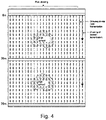
- the transmission period is 0.1 seconds, as illustrated in Fig. 3 , a display range of 75 m or more does not exist. Even when it exists, as illustrated in Fig. 4 , it is only a repeated display of a range from 0 m to 75 m.
- a transmission interval of transmission pulses is T
- (2D/1500) ⁇ T as illustrated in Fig. 5A
- a time difference between a transmission pulse and a reception echo corresponds to (2D/1500)
- the depth can be measured from this time difference.
- (2D/1500) ⁇ T as illustrated in Fig. 5B
- a reception echo arrives after the next transmission pulse is transmitted, it is not possible to know which transmission pulse the reception echo corresponds to, and a wrong depth is measured based on a time difference (FD). Therefore, conventionally, the condition of (2D/1500) ⁇ T is required.
- a measurement resolution in a traveling direction (horizontal direction) of a ship is described below with reference to Fig. 6 .
- a horizontal resolution ( ⁇ H) (m) in a case where sounding of a depth (D) (m) is performed at a ship speed (V) (m/s) is expressed by the following formula.
- ⁇ H VT > 2 DV/1500
- the measurement resolution ( ⁇ H) is 6.67 m.
- the horizontal resolution (measurement interval) can be determined regardless of a sounding depth.
- the horizontal resolution ( ⁇ H) is determined only from the transmission period (T) and the ship speed (V) regardless of the depth. In this way, the transmission period (T) can be shortened, sounding is possible regardless of the depth, and a high horizontal measurement resolution can be obtained.
- Patent Document 1 Japanese Patent No. 6402224 .
- a purpose of the present invention is to provide an underwater information display device that can solve such a problem.
- the present invention is an underwater information display device that transmits an ultrasonic wave, receives an echo reflected by an underwater target, and displays the echo.
- the underwater information display device includes:
- a ghost of a transmission signal and a ghost of an echo can be removed. Therefore, a display can be made easy to see, and an underwater object hidden in a ghost can be displayed.
- the effects described herein are not necessarily limited, and may be any effect described in the present invention. Further, the content of the present invention is not to be interpreted in a limited manner by the effects exemplified in the following description.
- the seabed is assumed as an example of an underwater target.
- the present invention can be similarly applied to targets other than the seabed.
- an echo from the seabed has a higher echo level than other objects such as fishes
- a ghost of the seabed as a reception ghost becomes conspicuous, and removal of the ghost of the seabed is a problem to be solved. That is, a ghost having a large level among reception ghosts is particularly to be removed. Further, a ghost is also an echo.
- an original reflection wave that arrives after being reflected by a target is referred to as an echo
- a reflection wave that is not the original reflection wave is referred to as a ghost.
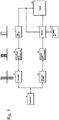
- a pulse generator 1 generates transmission trigger pulses with a varying interval.
- the transmission trigger pulses are supplied to a transmission signal generation part 2.
- the transmission signal generation part 2 forms a transmission signal sequence in which at least two temporally adjacent transmission signals are converted so as to be identifiable at the time of reception and have different intervals.
- a pseudo noise sequence signal for example, a gold code
- the transmission pulse is digitally modulated by pulse modulation, for example, BPSK (Binary Phase Shift Keying).
- a frequency of a carrier wave is several kHz -several hundred kHz.
- the transmission trigger pulses are supplied to a display 8.
- the display 8 is a display device such as a color liquid crystal display.
- the transmission signals with a varying interval generated by the transmission signal generation part 2 are supplied to a transmitter 3, and the transmitter 3 performs processing such as amplification.
- An output signal of the transmitter 3 is supplied to a transducer 4.
- An ultrasonic wave is emitted from the transducer 4 into the water.
- An echo of an emitted underwater ultrasonic wave is received by the transducer 4.
- a transmission signal sequence is formed in which an interval between transmission signals alternates between T and T + ⁇ T.
- Data received from the transducer 4 is supplied to a reception amplifier 5 and is subjected to processing such as amplification, and then, is supplied to a reception signal processing part 6.
- the reception signal processing part 6 subjects a reception signal to correlation processing by a pseudo noise sequence signal.
- a transmission signal and a pseudo noise sequence signal of a reception signal match each other, a signal with a large value is generated, and a transmission signal and a corresponding reception signal can be identified. Further, a signal after correlation processing is transmitted to a memory 7.
- An output of the reception signal processing part 6 is supplied to a memory 7 having a memory area corresponding to a display area of the display 8.
- An output of the memory 7 is supplied to the display 8.
- a trigger pulse indicating a timing of a transmission pulse from the pulse generator 1 is supplied to the memory 7 and the display 8, and the display 8 displays an echo received with respect to the transmission pulse.
- an interpolation part 9 is provided in connection with the memory 7.
- the interpolation part 9 performs interpolation processing using reception data read from the memory 7, and performs processing to write an interpolation value to the memory 7.
- Confirmed signals are signals including signals after the interpolation processing.
- a transmission trigger pulse is supplied to the display 8, and the timing of the transmission trigger pulse is displayed as a transmission line (0 m) on an upper side of the screen.
- An output signal from the memory 7 with respect to a transmission pulse is colored and displayed so as to extend from the transmission line.
- the interval between the transmission pulses varies. However, even at the maximum interval, when the underwater sonic speed is Vu and the distance to the target is D, it is (2D/Vu) or less.
- the horizontal resolution (measurement interval) can be determined regardless of a sounding depth.
- the horizontal resolution ( ⁇ H) is determined only from the transmission period (T) and the ship speed (V) regardless of the depth. In this way, the transmission period (T) can be shortened, sounding is possible regardless of the depth, and a high horizontal measurement resolution can be obtained.
- the resolution of the display in the horizontal direction (time direction) in the display 8 can be increased. Therefore, even for a relatively small object in the sea, a shape thereof can be displayed on the screen.
- Fig. 8 illustrates a display method when the memory 7 is provided as in the one embodiment of the present invention. Multiple temporarily continuous transmission and reception signals are sequentially stored in the memory, and only confirmed signals are drawn (displayed). Unconfirmed signals are stored in the memory 7. Since the memory 7 corresponds to a display screen of the display 8, reception signals corresponding to multiple transmission signals can be simultaneously displayed in the display 8.
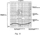
- Fig. 9 illustrates an example of the memory 7.
- the memory 7 has a capacity that can store data of 1,000 transmissions. In one transmission, data for each 0.01 m can be stored. When displaying underwater at a depth of 100 m, data of 10,000 pixels is stored.
- Fig. 10A illustrates transmission signals (P0, P1, P2, ⁇ ) transmitted with a constant transmission period (T).
- Fig. 10B illustrates reception signals received by a receiver.
- Fig. 10C schematically illustrates a display image based on the reception signals.
- a transmission line corresponding to the transmission signals (P0, P1, P2, ...) is a leftmost vertical line in Fig. 10C .
- X time
- a reception ghost for example, a seabed ghost
- R0' a reception ghost
- P2' a transmission ghost
- R1 an echo
- ' is used to indicate a ghost.
- a transmission ghost (P1') due to the transmission signal (PI) itself occurs at the same timing and thus can be ignored.
- the transmission ghost (P2') due to the transmission signal (P2) cannot be ignored.
- a reception ghost, a transmission ghost, and an echo are sequentially generated. Therefore, on the display screen, in addition to the display corresponding to the echo, the reception ghost and the transmission ghost are displayed, which hinders cognition of the target by the echo.
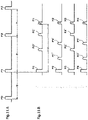
- Fig. 11A is used in description of transmission signals of the one embodiment of the present invention, in which, for example, two intervals T and T + ⁇ alternately appear.
- reception signals corresponding to the transmission signals P1, P2, P3 are as illustrated in Fig. 11B .
- a target of a certain depth for example, the seabed, is assumed.
- reception signals including a reception ghost (R0') corresponding to the previous transmission signal (P0), a transmission ghost (P2') due to the transmission signal (P2), and an echo (R1) are obtained.
- reception signals including a reception ghost (R1') corresponding to the previous transmission signal (P1), a transmission ghost (P3') due to the transmission signal (P3), and an echo (R2) are obtained.
- reception signals including a reception ghost (R2') corresponding to the previous transmission signal (P2), a transmission ghost (P4') due to the transmission signal (P4), and an echo (R3) are obtained.
- reception signals including a reception ghost (R3') corresponding to the previous transmission signal (P3), a transmission ghost (P5') due to the transmission signal (P5), and an echo (R4) are obtained.
- the transmission ghost and the reception ghost can be removed by being replaced with reception data at temporally corresponding positions of previous (or later) transmission signals.
- the interpolation part 9 (see Fig. 7 ) performs interpolation processing of such pre-value (or post-value) holding.
- the interpolation processing is replacement processing in which a ghost is removed and a temporally nearby echo is added.
- the time when a transmission ghost occurs is known when the transmission interval is known, and the time when a reception ghost occurs can also be known from the time when an echo occurs. Therefore, a ghost removal method in which a reception signal of a ghost part is forcibly set to zero data is also conceivable. In this method, an echo of a target such as a fish that exists at a position of a ghost is also removed, and thus, this method is not preferable.
- the interpolation processing is performed. Therefore, high-precision detection and display can be performed without removing information of a target that exists at a position of a ghost.
- a range in which the interpolation processing is performed is set to match a range in which a ghost exists and that is determined based on known information. Further, it is also possible that a level of a reception signal is monitored and the interpolation processing is performed within a range in which it is detected that a ghost of a predetermined level or higher exists.
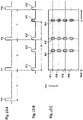
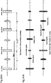
- Figs. 12A and 12B illustrate a part of a display of the one embodiment of the present invention.
- Fig. 12A illustrates a display before the interpolation is performed
- Fig. 12B illustrates a display after the interpolation is performed.
- the vertical and horizontal directions are interchanged with respect to those of the display of the display 8, the transmitting line is the leftmost vertical line in the drawings, and the horizontal direction is the depth direction.
- the reception ghost (RO'), the transmission ghost (P2'), and the echo (R1) are sequentially arranged, and, with respect to the transmission signal (P2), the reception ghost (R1'), the transmission ghost (P3'), and the echo (R2) are sequentially arranged.
- a reception signal (no signal or an echo) (Y11) exists with respect to the transmission signal (PI).
- a reception signal (Y12) exists with respect to the transmission signal (PI).
- the reception ghost (R1') is replaced by the reception signal (Y11), and a signal (Y11) same as the reception signal (Y11) is inserted in place of the ghost.
- the transmission ghost (P3') is replaced by the reception signal (Y12), and a signal (Y12) same as the reception signal (Y12) is inserted in place of the ghost.
- Other reception ghosts and transmission ghosts are also interpolated in the same way, and thus, an image with ghosts removed ( Fig. 12B ) can be displayed. Further, when a target exists at a position same as a ghost, a predicted value of an echo of the target can be displayed.
- Fig. 13 illustrates an example of the interpolation part 9 that performs the pre-value holding as described above.
- the reception signal read from the memory 7 is supplied to input terminals (a, b) of a switch circuit 11.
- a reception signal with respect to a transmission signal to be processed is supplied to one input terminal (a) of the switch circuit 11, and a processed (confirmed) reception signal is supplied to the other input terminal (b).
- a reception signal after interpolation is taken out to an output terminal (c) of the switch circuit 11, and this reception signal is written to the memory 7 as a processed reception signal.
- the switch circuit 11 is controlled by a switching signal from a terminal 12.
- Fig. 14A illustrates processed reception signals (with respect to the transmission signal (PI)) stored in memory 7, and Fig. 14B illustrates reception signals (with respect to the transmission signal (P2)) to be processed.
- Switching signals as illustrated in Fig. 14C are supplied to the switch circuit 11 at the timing of the reception ghost (R1') and the timing of the transmission ghost (P3').
- Reception signals after interpolation as illustrated in Fig. 14D are obtained from the switch circuit 11, and the reception signals after interpolation are written to the memory 7.
- the interpolation processing is not limited to the pre-holding, and it is also possible that average value interpolation is adopted.
- the reception ghost (R1' ) is replaced by an average value (Y11+Y31)/2 of a reception signal (Y11) with respect to another (temporally earlier) transmission signal (PI) at the same position as the reception ghost (R1') and a reception signal (Y31) with respect to another (temporally later) transmission signal (P2) at the same position as the reception ghost (R1').
- a transmission ghost is also similarly average value interpolated.
- Fig. 16 illustrates an example of the interpolation part 9 performing average value interpolation.
- a reception signal with respect to a transmission signal to be processed is supplied to one input terminal (a) of a switch circuit 13.
- Reception signals with respect to transmission signals before and after the transmission signal to be processed are read out from the memory 7 and are supplied to an additive circuit 14, and an additive output of the additive circuit 14 is supplied to a (1/2) multiplicative circuit 13.
- An average value signal of the previous and later reception signals is obtained from the (1/2) multiplicative circuit 13, and this average value signal is supplied to another input terminal (b) of the switch circuit 13.
- the switch circuit 13 is controlled by a switching signal from a terminal 16.
- the input terminal (a) is selected and a reception signal is taken out to an output terminal (c).
- the input terminal (b) is selected and an average value signal is taken out to the output terminal (c).
- the reception signal taken out to the output terminal (c) of the switch circuit 13 is returned to the memory 7 as a confirmed reception signal. In this way, a ghost is replaced by an average value signal, and ghost removal can be performed.
- the interpolation part 9 is not limited to having the circuit (hardware) structures as illustrated in the block diagrams described above, and may be realized by software processing using a microprocessor.
- a method for varying the interval of the transmission signals in addition to the method of switching between the two types of T and T + ⁇ , transmission signals with three types of intervals of T, T + ⁇ , and T + 2 ⁇ may be used, or transmission signals with four or more types of intervals may be used. It is set such that reception signals with respect to other transmission signals temporally adjacent to positions (phases) of transmission ghosts exist.
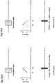
- a reception image as illustrated in Fig. 17A is displayed before the ghost removal processing.
- a seabed echo near 40m 4 lines of transmission ghosts and 3 lines of reception ghosts are displayed.
- Fig. 17B it is possible that the ghost component is removed by the present invention, and only the seabed echo is displayed. Therefore, the display image becomes easy to see, and further, a target such as a fish and a fish school can be clearly displayed.
- two temporally adjacent transmission signals are converted so as to be identifiable at the time of reception by being converted with different pseudo noise signals, and have different intervals.
- pseudo noise signals instead of the pseudo noise signals, chirp signals are used.
- a linear FM (Frequency Modulation) signal referred to as an up chirp of which a frequency sweeps from a low frequency to a high frequency as illustrated in Fig. 18A and a linear FM signal referred to as a down chirp of which a frequency conversely sweeps from a high frequency to a low frequency as illustrated in Fig. 18B are alternately transmitted.
- reception signals to correlation processing ghosts can be removed in the same way as in the one embodiment.
- a correlation result similar to that of the pseudo noise signals can be obtained. That is, for an up chirp, a sharp peak can be obtained by correlating with a replica signal of the up chirp. However, for a down chirp signal, no peak appears.
- Fig. 19 illustrates a schematic diagram of this. Since an up chirp and a down chirp are alternately transmitted, when an up chirp is transmitted, a down chirp appears as a ghost between a transmission line and a seabed signal. As illustrated in Fig. 19A , a transmission interval is T seconds from an up chirp to a down chirp, and T + ⁇ T from a down chirp to an up chirp. In this case, an image is as illustrated in Fig. 19B , and is the same as Fig. 12 of the case where pseudo noise signals are used. Therefore, ghost removal processing can be performed using the same interpolation processing as in the one embodiment.
- Fig. 20 is an example in which alternately transmitted up chirp signals and down chirp signals are received and imaged.
- a reception signal level is colored and displayed from 0 m to a deep depth for each transmission
- a down chirp reception signal for example, the seabed
- a down chirp transmission signal that appear during an up chirp transmission have a lower signal level than an original echo, but appear on an image.
- positions where a seabed ghost and a transmission ghost appear are different, and thus they can be removed by interpolation processing.
- a method of the interpolation is the same as that in the one embodiment in which pseudo-noise signals are used.
- ghost removal can be performed using chirp signals as illustrated in Fig. 18 instead of the pseudo-noise signals.
- the chirp signals there are only two types of signals, up chirp signals and down chirp signals, and it is not possible to prepare three or more types of transmission signals as in the case of the pseudo-noise signals. Therefore, it is not possible to perform interpolation processing by preparing three types of transmission periods that is performed using the pseudo-noise signals.
Landscapes
- Engineering & Computer Science (AREA)
- Radar, Positioning & Navigation (AREA)
- Remote Sensing (AREA)
- Physics & Mathematics (AREA)
- Computer Networks & Wireless Communication (AREA)
- General Physics & Mathematics (AREA)
- Acoustics & Sound (AREA)
- Measurement Of Velocity Or Position Using Acoustic Or Ultrasonic Waves (AREA)
Applications Claiming Priority (1)
| Application Number | Priority Date | Filing Date | Title |
|---|---|---|---|
| PCT/JP2019/027904 WO2021009840A1 (ja) | 2019-07-16 | 2019-07-16 | 水中情報表示装置 |
Publications (2)
| Publication Number | Publication Date |
|---|---|
| EP4001963A1 true EP4001963A1 (de) | 2022-05-25 |
| EP4001963A4 EP4001963A4 (de) | 2023-03-22 |
Family
ID=70000364
Family Applications (1)
| Application Number | Title | Priority Date | Filing Date |
|---|---|---|---|
| EP19937749.0A Withdrawn EP4001963A4 (de) | 2019-07-16 | 2019-07-16 | Unterwasserinformationsanzeigevorrichtung |
Country Status (4)
| Country | Link |
|---|---|
| US (1) | US20220206143A1 (de) |
| EP (1) | EP4001963A4 (de) |
| JP (1) | JP6664731B1 (de) |
| WO (1) | WO2021009840A1 (de) |
Families Citing this family (1)
| Publication number | Priority date | Publication date | Assignee | Title |
|---|---|---|---|---|
| WO2021009840A1 (ja) * | 2019-07-16 | 2021-01-21 | 株式会社AquaFusion | 水中情報表示装置 |
Family Cites Families (11)
| Publication number | Priority date | Publication date | Assignee | Title |
|---|---|---|---|---|
| JPS58124976A (ja) | 1982-01-21 | 1983-07-25 | Toshihiro Tsumura | 移動物体の現在位置および方位測定装置 |
| JPS57149475U (de) * | 1982-02-24 | 1982-09-20 | ||
| JPS58150878A (ja) * | 1982-03-03 | 1983-09-07 | Mitsubishi Electric Corp | 物体検出装置 |
| JPS58117473A (ja) * | 1982-09-27 | 1983-07-13 | Aloka Co Ltd | 超音波装置 |
| US4855961A (en) * | 1986-07-31 | 1989-08-08 | Woods Hole Oceanographic Institute | Imaging apparatus |
| JP5383374B2 (ja) * | 2009-08-05 | 2014-01-08 | 古野電気株式会社 | 水中探知装置 |
| JP6700054B2 (ja) * | 2016-02-04 | 2020-05-27 | 学校法人桐蔭学園 | 非接触音響探査システム |
| US20180011190A1 (en) * | 2016-07-05 | 2018-01-11 | Navico Holding As | High Ping Rate Sonar |
| JP6402224B1 (ja) * | 2017-07-26 | 2018-10-10 | 株式会社AquaFusion | 音響測深装置及び音響測深方法 |
| WO2020110190A1 (ja) * | 2018-11-27 | 2020-06-04 | 株式会社AquaFusion | 水中情報可視化装置 |
| WO2021009840A1 (ja) * | 2019-07-16 | 2021-01-21 | 株式会社AquaFusion | 水中情報表示装置 |
-
2019
- 2019-07-16 WO PCT/JP2019/027904 patent/WO2021009840A1/ja not_active Ceased
- 2019-07-16 US US17/625,135 patent/US20220206143A1/en not_active Abandoned
- 2019-07-16 JP JP2019560405A patent/JP6664731B1/ja active Active
- 2019-07-16 EP EP19937749.0A patent/EP4001963A4/de not_active Withdrawn
Also Published As
| Publication number | Publication date |
|---|---|
| US20220206143A1 (en) | 2022-06-30 |
| JP6664731B1 (ja) | 2020-03-13 |
| JPWO2021009840A1 (ja) | 2021-09-13 |
| WO2021009840A1 (ja) | 2021-01-21 |
| EP4001963A4 (de) | 2023-03-22 |
Similar Documents
| Publication | Publication Date | Title |
|---|---|---|
| JP5415145B2 (ja) | レーダ装置 | |
| JP5383374B2 (ja) | 水中探知装置 | |
| JP5658871B2 (ja) | 信号処理装置、レーダ装置、信号処理プログラム及び信号処理方法 | |
| CN102193089B (zh) | 回波信号处理装置、雷达装置、回波信号处理方法及程序 | |
| JP4928171B2 (ja) | レーダ装置及びレーダ画像表示方法 | |
| US10718858B2 (en) | Echo measuring apparatus, echo sounding apparatus, multibeam echo measuring apparatus, multibeam echo sounding apparatus and aperture synthetic sonar | |
| GB2503351A (en) | Underwater detection device | |
| JP5628590B2 (ja) | 干渉除去装置、信号処理装置、レーダ装置、干渉除去方法およびプログラム | |
| US9310483B2 (en) | Device and method for transceiving ultrasonic wave | |
| JP6255449B1 (ja) | 音響測深装置、音響測深方法及びマルチビーム音響測深装置 | |
| JP2017129520A (ja) | レーダ装置及び物標追尾方法 | |
| JP6402224B1 (ja) | 音響測深装置及び音響測深方法 | |
| JP6587564B2 (ja) | 音響測定装置、音響測定方法、マルチビーム音響測定装置及び開口合成ソナー | |
| CN102798841A (zh) | 影像显示装置以及雷达装置 | |
| EP3605144A1 (de) | Echolotungsvorrichtung und echolotungsverfahren | |
| JP2007064768A (ja) | 水中探知装置 | |
| EP4001963A1 (de) | Unterwasserinformationsanzeigevorrichtung | |
| JP2006170926A (ja) | 水中探知装置 | |
| US11802949B2 (en) | Underwater information visualizing device | |
| JPH03269284A (ja) | 三次元的表示レーダ | |
| JP2018010006A (ja) | 音響測深装置、音響測深方法及びマルチビーム音響測深装置 | |
| JP2001141817A (ja) | レーダ装置 | |
| JP6757083B2 (ja) | 音響測深装置及びマルチビーム音響測深装置 | |
| WO2014125960A1 (ja) | 信号処理装置、及び信号処理方法 | |
| JP2000321349A (ja) | マリンレーダ装置 |
Legal Events
| Date | Code | Title | Description |
|---|---|---|---|
| STAA | Information on the status of an ep patent application or granted ep patent |
Free format text: STATUS: THE INTERNATIONAL PUBLICATION HAS BEEN MADE |
|
| PUAI | Public reference made under article 153(3) epc to a published international application that has entered the european phase |
Free format text: ORIGINAL CODE: 0009012 |
|
| STAA | Information on the status of an ep patent application or granted ep patent |
Free format text: STATUS: REQUEST FOR EXAMINATION WAS MADE |
|
| 17P | Request for examination filed |
Effective date: 20211215 |
|
| AK | Designated contracting states |
Kind code of ref document: A1 Designated state(s): AL AT BE BG CH CY CZ DE DK EE ES FI FR GB GR HR HU IE IS IT LI LT LU LV MC MK MT NL NO PL PT RO RS SE SI SK SM TR |
|
| DAV | Request for validation of the european patent (deleted) | ||
| DAX | Request for extension of the european patent (deleted) | ||
| REG | Reference to a national code |
Ref country code: DE Ref legal event code: R079 Free format text: PREVIOUS MAIN CLASS: G01S0015100000 Ipc: G01S0015960000 |
|
| A4 | Supplementary search report drawn up and despatched |
Effective date: 20230217 |
|
| RIC1 | Information provided on ipc code assigned before grant |
Ipc: G01S 7/62 20060101ALI20230213BHEP Ipc: G01S 7/60 20060101ALI20230213BHEP Ipc: G01S 7/527 20060101ALI20230213BHEP Ipc: G01S 15/10 20060101ALI20230213BHEP Ipc: G01S 15/32 20060101ALI20230213BHEP Ipc: G01S 15/96 20060101AFI20230213BHEP |
|
| STAA | Information on the status of an ep patent application or granted ep patent |
Free format text: STATUS: THE APPLICATION IS DEEMED TO BE WITHDRAWN |
|
| 18D | Application deemed to be withdrawn |
Effective date: 20230919 |