EP4000174B1 - Vorrichtung und verfahren zur steuerung oder regelung einer bewegung eines ziehkissens einer ziehkissenpresse - Google Patents
Vorrichtung und verfahren zur steuerung oder regelung einer bewegung eines ziehkissens einer ziehkissenpresse Download PDFInfo
- Publication number
- EP4000174B1 EP4000174B1 EP20743110.7A EP20743110A EP4000174B1 EP 4000174 B1 EP4000174 B1 EP 4000174B1 EP 20743110 A EP20743110 A EP 20743110A EP 4000174 B1 EP4000174 B1 EP 4000174B1
- Authority
- EP
- European Patent Office
- Prior art keywords
- speed
- die cushion
- current
- setpoint
- controller
- Prior art date
- Legal status (The legal status is an assumption and is not a legal conclusion. Google has not performed a legal analysis and makes no representation as to the accuracy of the status listed.)
- Active
Links
Images


Classifications
-
- H—ELECTRICITY
- H02—GENERATION; CONVERSION OR DISTRIBUTION OF ELECTRIC POWER
- H02P—CONTROL OR REGULATION OF ELECTRIC MOTORS, ELECTRIC GENERATORS OR DYNAMO-ELECTRIC CONVERTERS; CONTROLLING TRANSFORMERS, REACTORS OR CHOKE COILS
- H02P23/00—Arrangements or methods for the control of AC motors characterised by a control method other than vector control
- H02P23/0004—Control strategies in general, e.g. linear type, e.g. P, PI, PID, using robust control
-
- H—ELECTRICITY
- H02—GENERATION; CONVERSION OR DISTRIBUTION OF ELECTRIC POWER
- H02P—CONTROL OR REGULATION OF ELECTRIC MOTORS, ELECTRIC GENERATORS OR DYNAMO-ELECTRIC CONVERTERS; CONTROLLING TRANSFORMERS, REACTORS OR CHOKE COILS
- H02P27/00—Arrangements or methods for the control of AC motors characterised by the kind of supply voltage
- H02P27/04—Arrangements or methods for the control of AC motors characterised by the kind of supply voltage using variable-frequency supply voltage, e.g. inverter or converter supply voltage
- H02P27/06—Arrangements or methods for the control of AC motors characterised by the kind of supply voltage using variable-frequency supply voltage, e.g. inverter or converter supply voltage using DC to AC converters or inverters
- H02P27/08—Arrangements or methods for the control of AC motors characterised by the kind of supply voltage using variable-frequency supply voltage, e.g. inverter or converter supply voltage using DC to AC converters or inverters with pulse width modulation
-
- B—PERFORMING OPERATIONS; TRANSPORTING
- B21—MECHANICAL METAL-WORKING WITHOUT ESSENTIALLY REMOVING MATERIAL; PUNCHING METAL
- B21D—WORKING OR PROCESSING OF SHEET METAL OR METAL TUBES, RODS OR PROFILES WITHOUT ESSENTIALLY REMOVING MATERIAL; PUNCHING METAL
- B21D24/00—Special deep-drawing arrangements in, or in connection with, presses
- B21D24/10—Devices controlling or operating blank holders independently, or in conjunction with dies
- B21D24/14—Devices controlling or operating blank holders independently, or in conjunction with dies pneumatically or hydraulically
-
- F—MECHANICAL ENGINEERING; LIGHTING; HEATING; WEAPONS; BLASTING
- F04—POSITIVE - DISPLACEMENT MACHINES FOR LIQUIDS; PUMPS FOR LIQUIDS OR ELASTIC FLUIDS
- F04B—POSITIVE-DISPLACEMENT MACHINES FOR LIQUIDS; PUMPS
- F04B17/00—Pumps characterised by combination with, or adaptation to, specific driving engines or motors
- F04B17/03—Pumps characterised by combination with, or adaptation to, specific driving engines or motors driven by electric motors
-
- F—MECHANICAL ENGINEERING; LIGHTING; HEATING; WEAPONS; BLASTING
- F04—POSITIVE - DISPLACEMENT MACHINES FOR LIQUIDS; PUMPS FOR LIQUIDS OR ELASTIC FLUIDS
- F04B—POSITIVE-DISPLACEMENT MACHINES FOR LIQUIDS; PUMPS
- F04B49/00—Control, e.g. of pump delivery, or pump pressure of, or safety measures for, machines, pumps, or pumping installations, not otherwise provided for, or of interest apart from, groups F04B1/00 - F04B47/00
- F04B49/06—Control using electricity
-
- G—PHYSICS
- G05—CONTROLLING; REGULATING
- G05B—CONTROL OR REGULATING SYSTEMS IN GENERAL; FUNCTIONAL ELEMENTS OF SUCH SYSTEMS; MONITORING OR TESTING ARRANGEMENTS FOR SUCH SYSTEMS OR ELEMENTS
- G05B19/00—Programme-control systems
- G05B19/02—Programme-control systems electric
- G05B19/18—Numerical control [NC], i.e. automatically operating machines, in particular machine tools, e.g. in a manufacturing environment, so as to execute positioning, movement or co-ordinated operations by means of programme data in numerical form
- G05B19/182—Numerical control [NC], i.e. automatically operating machines, in particular machine tools, e.g. in a manufacturing environment, so as to execute positioning, movement or co-ordinated operations by means of programme data in numerical form characterised by the machine tool function, e.g. thread cutting, cam making, tool direction control
-
- G—PHYSICS
- G05—CONTROLLING; REGULATING
- G05D—SYSTEMS FOR CONTROLLING OR REGULATING NON-ELECTRIC VARIABLES
- G05D15/00—Control of mechanical force or stress; Control of mechanical pressure
- G05D15/01—Control of mechanical force or stress; Control of mechanical pressure characterised by the use of electric means
-
- H—ELECTRICITY
- H02—GENERATION; CONVERSION OR DISTRIBUTION OF ELECTRIC POWER
- H02P—CONTROL OR REGULATION OF ELECTRIC MOTORS, ELECTRIC GENERATORS OR DYNAMO-ELECTRIC CONVERTERS; CONTROLLING TRANSFORMERS, REACTORS OR CHOKE COILS
- H02P23/00—Arrangements or methods for the control of AC motors characterised by a control method other than vector control
- H02P23/16—Controlling the angular speed of one shaft
-
- H—ELECTRICITY
- H02—GENERATION; CONVERSION OR DISTRIBUTION OF ELECTRIC POWER
- H02P—CONTROL OR REGULATION OF ELECTRIC MOTORS, ELECTRIC GENERATORS OR DYNAMO-ELECTRIC CONVERTERS; CONTROLLING TRANSFORMERS, REACTORS OR CHOKE COILS
- H02P25/00—Arrangements or methods for the control of AC motors characterised by the kind of AC motor or by structural details
-
- G—PHYSICS
- G05—CONTROLLING; REGULATING
- G05B—CONTROL OR REGULATING SYSTEMS IN GENERAL; FUNCTIONAL ELEMENTS OF SUCH SYSTEMS; MONITORING OR TESTING ARRANGEMENTS FOR SUCH SYSTEMS OR ELEMENTS
- G05B2219/00—Program-control systems
- G05B2219/30—Nc systems
- G05B2219/45—Nc applications
- G05B2219/45142—Press-line
-
- Y—GENERAL TAGGING OF NEW TECHNOLOGICAL DEVELOPMENTS; GENERAL TAGGING OF CROSS-SECTIONAL TECHNOLOGIES SPANNING OVER SEVERAL SECTIONS OF THE IPC; TECHNICAL SUBJECTS COVERED BY FORMER USPC CROSS-REFERENCE ART COLLECTIONS [XRACs] AND DIGESTS
- Y02—TECHNOLOGIES OR APPLICATIONS FOR MITIGATION OR ADAPTATION AGAINST CLIMATE CHANGE
- Y02P—CLIMATE CHANGE MITIGATION TECHNOLOGIES IN THE PRODUCTION OR PROCESSING OF GOODS
- Y02P70/00—Climate change mitigation technologies in the production process for final industrial or consumer products
- Y02P70/10—Greenhouse gas [GHG] capture, material saving, heat recovery or other energy efficient measures, e.g. motor control, characterised by manufacturing processes, e.g. for rolling metal or metal working
Definitions
- the present invention relates to a device for controlling or regulating a movement of a die cushion of a die cushion press and a method for controlling or regulating a movement of a die cushion of a die cushion press
- Die cushion presses are known in the art.
- the EP 1 882 534 a die cushion press based on a direct pump drive, with which it is possible to recover process energy.
- Characteristic of the die cushion press based on a pump direct drive is that the control device controls a torque of the electric motor of the pump direct drive based on the die cushion pressure command and the detected pressure so that the die cushion pressure represents a pressure that matches the die cushion pressure command.
- the control device described in the EP 1 882 534 The die cushion press shown has a pressure control which outputs a motor torque as a control value for the electric motor.
- the torque setpoint on the electric motor In addition to the load pressure on the pump, which is directly proportional to the motor torque, the torque setpoint on the electric motor also requires control value components for the acceleration and deceleration of the inertia in the direct pump drive. In addition, control value components are required in the motor torque, which must compensate for friction and motor losses, for example. Neither acceleration nor loss components are commanded to the electric motor with the control described. As a result, the motor torque to be commanded or the motor current is subject to very strong changes depending on the motor, pump and cylinder losses that occur. However, this leads to disadvantageously, the quality and dynamics of the control of the electric motor known in the state of the art do not meet the requirements of today's forming processes in which drawing cushions are used.
- US 2005/262915 A1 relates to a die damping device which is driven to raise or lower a damping pad by applying an upward exciting force, and more particularly to a die damping device which mitigates a shock generated in a press machine.
- US 2011/045113 A1 relates to a die cushion device in which a shock absorber device relieves the shock between a cushion and a support portion.
- the shock absorber device includes a cushion portion and an elastic portion.
- the cushion portion generates a reaction force in accordance with the relative speed of the cushion pad with respect to the support portion.
- the elastic portion generates a reaction force in accordance with the relative displacement of the cushion pad with respect to the support portion.
- the controller portion controls a servo motor so that a speed difference between the speed of the sliding member and the speed of the support portion is set to a predetermined target speed difference value that changes with time.
- WO 2019/025478 A1 relates to a method for controlling the output pressure of a hydraulic drive system using a rotational speed as a manipulated variable, wherein the hydraulic drive system has a hydraulic pump and a motor drive driving the hydraulic pump.
- the invention therefore provides a device for controlling or regulating a movement of a die cushion of a die cushion press with the features of patent claim 1.
- the nominal current includes the electrical current provided for the operation of the electric drive based on the target current.
- specifying a motor speed allows a very simple controller switch between position and force control of the drawing cylinder. Since the controller's output signal in both controller modes is the motor speed, the transition can be smooth and jerk-free. This functionality is required in a drawing cushion during the transition from the pre-acceleration phase (position-controlled) to the drawing process (force-controlled). What was said above also applies to the transition from the drawing process (force-controlled) to the return movement (position-controlled).
- the speed of the die cushion represents the disturbance variable for the force control. This speed is measured on the die cushion or is specified by the speed of the ram in this phase and is therefore known. If the output signal of the force control is a speed, the known value of the die cushion speed can advantageously be added to the control loop as a disturbance variable, thus ensuring a further improvement in the force control.
- a calculation of the target rotational speed is provided based on drawing punch information detected by a drawing punch detector.
- the drawing punch information includes, for example, the pressure in the cylinder chamber or the position of the drawing cushion.
- the drawing punch detector is, for example, a pressure sensor for detecting the pressure in a first and a second chamber of the hydraulic cylinder. The pressure is measured by the drawing punch detector. An adequate force, in particular the actual force, is determined via the measured pressure and the area of the corresponding chamber of the hydraulic cylinder.
- the inexpensive pressure sensors already installed in the system can advantageously be used.
- the drawing punch detector can be designed as a force measuring cell which is inserted on the piston rod of the hydraulic cylinder between the piston rod and the workpiece.
- the drawing punch detector comprises acceleration sensors.
- control value transmitter comprises a position controller, a speed controller or a force controller.
- force controllers can advantageously be used during the drawing process to determine a target speed.
- position controllers and speed controllers can be used to determine a target speed.
- the device comprises a current detector for detecting the nominal current of the electric drive.
- the current controller uses a target current which is a difference between the target current and the feedback of the nominal current of the electric drive detected by the current detector.
- the electric drive comprises three phases and the motor torque is derived from the electric currents of the three phases.
- the electric currents in the three phases of the electric drive are measured using the current detector.
- Only the electrical currents in two phases of the electric drive need to be measured and the current of the third phase can be determined.
- the device comprises a speed sensor for detecting an instantaneous speed of the electric drive.
- the speed controller uses a target speed which is a difference between the target speed and the feedback of the instantaneous speed of the electric drive detected by the speed sensor.
- the speed controller uses a target speed including a disturbance.
- the speed can be applied as a disturbance variable.
- the motor pump unit can be provided with a speed that corresponds to the speed of the tool. This means that with information about the speed already provided in advance, overshoots in the system, such as pressure maxima or pressure minima of the motor pump unit, can be avoided and the system operates more dynamically and the load on the control value transmitter is reduced.
- the target speed of the actuator is proportional to the force or pressure increase within the die cushion press.
- a speed is specified via a speed controller and disturbances and thus losses are regulated.
- stick-slip behavior of the motor pump unit can be reduced via the specified speed.
- the speed controller provides a current for the specified speed, from which the torque for the motor is generated.
- the invention further provides, according to a second aspect of the present invention, a method for controlling or regulating a movement of a die cushion of a die cushion press with the features specified in claim 8.
- the invention therefore provides a method for controlling or regulating a movement of a die cushion of a die cushion press with the features of patent claim 7.
- the target speed is calculated on the basis of drawing punch information.
- the drawing punch information is detected by a drawing punch detector.
- the current controller uses a target current.
- the target current is a difference between the target current and the feedback of the rated current of the electric drive detected by a current detector.
- the target speed is calculated on the basis of drawing punch information.
- the drawing punch information is detected by a drawing punch detector.
- the current controller uses a target current which is a difference between the target current and the feedback of the rated current of the electric drive detected by a current detector.
- the speed controller uses a target speed.
- the target speed is a difference between the target speed and the feedback of the instantaneous speed of the electric drive detected by a speed sensor.
- the speed controller uses a target speed which includes a disturbance variable.
- the invention further provides, according to a third aspect of the present invention, a die cushion press comprising a device according to claims 1 to 7.
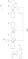
- Fig. 1 shows a block diagram illustrating an embodiment of a device according to the invention for controlling or regulating a movement of a die cushion of a die cushion press.
- Fig. 1 the device 10 is shown comprising a control circuit for controlling a die cushion press with a cascade connection of a control value transmitter 11, a speed controller 12, a current controller 13 and a motor control device 14.
- the control value transmitter 11 can be designed as a position controller, speed controller or as a force controller.
- the control value transmitter 11 receives a difference between a die cushion information, for example the target force F S and an actual force F I , as a control variable in the force transmission or the actual drawing process of the die cushion press.
- the target force F S is the reference variable (target value).
- the actual force F I comprises drawing punch information and results from the difference between the forces, which corresponds to the pressure in the two chambers of the hydraulic cylinder. The force is determined via the measured pressure and the area of the corresponding chamber of the hydraulic cylinder. The actual force F I results from the difference, since both chambers of the hydraulic cylinder have a mutual effect on one another.
- the pressure in the respective chamber is determined via a drawing punch detector 16 and 19.
- the drawing punch detector 16, 19 is, for example, a pressure sensor.
- the pressure sensors provided in the hydraulic cylinder can be used as a pressure sensor, for example.
- the drawing punch detector 16, 19 is designed as a force measuring cell.
- the drawing punch detector 16,19 is designed as a position sensor, for example an acceleration sensor.
- the manipulated variable provided to the actuating device 11 results from the difference between the desired force F S and the actual force F I .
- the actuating device 11 provides a desired speed n S to the speed controller 12.
- the command variable provided to the speed controller 12 is a difference between the desired speed n S provided by the actuating device 11, the instantaneous speed (actual speed) n I and the disturbance variable 30.
- the speed controller 12 provides a desired current I S to the current controller 13.
- the reference variable provided to the current controller 13 is a difference between the target current I S provided by the speed controller 12 and the actual current I S .
- the current controller 13 provides Based on the reference variable provided by the speed controller 12, a control signal is provided for controlling the motor control device 14.
- the control signal can, for example, comprise a pulse-width modulated voltage.
- the motor control device 14, for example a frequency converter, converts the pulse-width modulated voltage into a nominal current for operating the electrical machine 15 for driving the motor pump unit 20.
- the nominal current is the electrical current intensity consumed by the electrical drive 15 when the motor pump unit 20 and die cushion press are in operation, based on the control signal provided to the motor control device 14.
- the electrical drive 15 is, for example, a three-phase AC motor.
- the motor pump unit 20 provides the hydraulic energy for operating the die cushion press.
- a current detector 17 is connected to the output of the motor control device 14.
- the current detector 17 determines the electrical current in the three phases of the electric drive 15 and provides the determined electrical current via feedback to the current controller 13 for calculating a control signal.
- the value of the electrical current in the three phases of the electric drive 15 is determined via the current detector 17.
- current detectors 17 present on the electric drive 15 can be used to determine the actual current I S and feed it back to the current controller 13 for further processing. This makes it easier to derive the actual speed of the electric drive 15 and thus to make the control or the system to be controlled more dynamic. In addition, the control bandwidth in the system is increased.
- control signal for the electric drive can be provided by a control via a controlled current at the current regulator 13.
- a speed sensor 18 is connected to the electric drive 15 of the motor pump unit 20.
- the speed sensor 18 determines the instantaneous speed n I of the electric drive 15 and provides the determined instantaneous speed n I via feedback to the speed controller 12 for calculating a target current I S.
- Conventional speed sensors 12, for example those already provided on the electric drive 15, can be used to determine the speed of the electric drive 15. Additional control of the speed can advantageously improve the dynamics of the current control in the inner loop of the overall control. of the electric drive 15.
- the electric drive 15 can be controlled via a controlled rotating field by means of the speed sensors already provided on the electric drive 15.
- the disturbance variable 30 is taken into account.
- the speed is applied as disturbance variable 30.
- the speed of the die cushion can be switched as a disturbance variable for the force control. This speed is measured on the die cushion or is specified by the speed of the ram in this phase and is therefore known. If the output signal of the force control is a speed, the known value of the die cushion speed can advantageously be applied as a disturbance variable to the control loop and thus ensures a further improvement in the force control.
- Fig. 2 shows a schematic flow diagram to illustrate a possible embodiment of a method according to the invention for controlling or regulating a movement of a die cushion of a die cushion press.
- the method comprises several steps.
- a die cushion setting value command and die cushion information are received by the setting value transmitter 11.
- the die cushion information includes, for example, the target force F S .
- a target speed n S is calculated by the control value generator 11 based on the received die cushion control value command and the die cushion information.
- the target speed n S is calculated from the difference between the target force F S and the actual force I S .
- the actual force I S is the difference between the products of the current pressure in the chambers of the hydraulic cylinder and the area of the hydraulic cylinder.
- the pressure in the chambers can be determined via the drawing punch detectors 16, 19, for example pressure sensors.
- the target speed n S comprises a difference between the instantaneous speed n I fed back by the drive machine 15 and an applied disturbance variable, for example the speed of the die cushion.
- the instantaneous speed n I of the electric drive machine 15 is determined by a speed sensor 18.
- a target current I S is calculated by the speed controller 12 based on the calculated target speed n S.
- the target is calculated by the speed controller 12 based on the calculated target speed n S.
- Current I S is the difference between the target current I S provided by the control value transmitter 12 and the actual current I I provided by the motor control device 14 to the electric drive 15.
- the actual current I I is provided by feedback.
- the electrical current strength of the actual current I I is determined, for example, by a current detector.
- a control signal is calculated by the current controller 13 based on the target current I S provided by the speed controller 12.
- the control signal can, for example, comprise a pulse-width-modulated voltage.
- the motor control device 14, for example a frequency converter, converts the pulse-width-modulated voltage in a further step S5 into a nominal current for operating the electrical machine 15 for driving the fluid-hydraulic motor pump unit 20 for moving a die cushion of a die cushion press.
- Fig. 3a to 3d show a diagram to explain the force control in a deep drawing process including disturbance variable control in a possible embodiment of a device according to the invention for controlling or regulating a movement of a drawing cushion of a drawing cushion press.
- FIG. 3a to 3d A deep drawing process is shown, whereby the pre-acceleration of the drawing cushion was activated. The measurement was carried out with a simulation tool in order to prevent any damage caused by errors during commissioning. The Fig. 3a to 3d The test shows stable force control for the entire deep-drawing stroke. The force builds up without any significant overshoot.
- Fig. 3a the ram and cylinder positions 1 to 4 of the die cushion are shown.
- the curves are one behind the other and the cylinders move in parallel.
- the die cushion is actively pre-accelerated in the time range from 0s to 1s.
- the ram hits the die cushion and displaces it.
- the forming process takes place in the time range from 1s to 7s.
- the ram moves upwards while the die cushion remains in the pressing position.
- the formed part can be removed (see time range 7s to 10s).
- the die cushion cylinders return to the starting position.
- the new formed part can be inserted.
- Fig. 3b the speed of the die cushion cylinders 1-4 and the speed of the ram are shown.
- the drawing cylinders are pre-accelerated.
- the ram and die cushion come into contact.
- the die cushion is displaced by the ram, so the speed of the ram and die cushion are identical.
- Fig. 3c shows the force on the drawing cylinders calculated from the chamber pressures. This force represents the controlled variable during the drawing process in the time range from 1s to 7s.
- Fig. 3c shows the control quality of the force control at a constant setpoint of 250kN per cylinder. The actual force follows the setpoint profile almost perfectly even though the die cushion cylinder is moving (cf. Fig. 3b ).
- This force control quality can only be achieved due to the force control by means of speed specification according to the present invention, since this is the only way to implement the control disturbance variable (speed of the cylinder).
- any hydraulic mechanical losses that occur, such as friction are compensated for by the speed specification of the force controller.
- Fig. 3d shows the pressures on the A side and B side of the die cushion cylinder. From the respective pressures, the respective output force of the die cylinder can be calculated via the area of the die cylinder (cf. Fig. 3c ).
- the invention relates to a device and a method for controlling or regulating a movement of a die cushion of a die cushion press.
- the device has a control value transmitter (11), a speed controller (12), a current controller (13) and a motor control device (14) for providing a nominal current for an electric drive (15) of a fluid-hydraulic motor pump unit (20) for moving a die cushion of a die cushion press.
- the control value transmitter (11) is provided for calculating a target speed based on a die cushion control value command and die cushion information.
- the speed controller (12) calculates a target current based on the target speed.
- the current controller (13) calculates a control signal based on the target current and the motor control device (14) calculates the nominal current based on the control current.
Landscapes
- Engineering & Computer Science (AREA)
- Power Engineering (AREA)
- Mechanical Engineering (AREA)
- Physics & Mathematics (AREA)
- General Physics & Mathematics (AREA)
- Automation & Control Theory (AREA)
- General Engineering & Computer Science (AREA)
- Human Computer Interaction (AREA)
- Manufacturing & Machinery (AREA)
- Shaping Metal By Deep-Drawing, Or The Like (AREA)
- Control Of Presses (AREA)
Description
- Die vorliegende Erfindung betrifft eine Vorrichtung zur Steuerung oder Regelung einer Bewegung eines Ziehkissens einer Ziehkissenpresse und ein Verfahren zur Steuerung oder Regelung einer Bewegung eines Ziehkissens einer Ziehkissenpresse
- Ziehkissenpressen sind im Stand der Technik bekannt. Beispielsweise beschreibt die
EP 1 882 534 eine Ziehkissenpresse auf Basis eines Pumpendirektantriebs, mit dem es möglich sei, Prozessenergie zurückzugewinnen. - Kennzeichnend für die Ziehkissenpresse auf Basis eines Pumpendirektantriebs ist, dass die Steuervorrichtung ein Drehmoment des Elektromotors des Pumpendirektantriebs auf der Grundlage des Ziehkissendruckbefehls und des detektierten Drucks so steuert, dass der Ziehkissendruck einen Druck darstellt, der mit dem Ziehkissendruckbefehl übereinstimmt. Diesbezüglich umfasst die in der
EP 1 882 534 dargestellte Ziehkissenpresse eine Druckregelung, welche als Stellwert für den Elektromotor ein Motormoment ausgibt. - Neben dem Lastdruck an der Pumpe, welcher direktproportional zum Motormoment ist, benötigt der Drehmomenten Sollwert an dem Elektromotor aber auch Stellwertanteile für die Beschleunigung und Abbremsung im Pumpendirektantrieb befindlicher Trägheit. Darüber hinaus werden Stellwertanteile im Motormoment benötigt, die beispielsweise Reibungs- und Motorverluste kompensieren müssen. Weder Beschleunigungs- noch Verlustanteile werden mit der beschriebenen Steuerung dem Elektromotor kommandiert. In der Konsequenz unterliegt das zu kommandierende Motormoment bzw. der Motorstrom sehr starken Änderungen in Abhängigkeit der auftretenden Motor-, Pumpen- und Zylinderverluste. Dies führt jedoch in nachteilhafter Weise dazu, dass die Qualität und die Dynamik der im Stand der Technik bekannten Ansteuerung des Elektromotors nicht die Anforderung an heutige Umformprozesse bei denen Ziehkissen zum Einsatz kommen erfüllen.
- Vor diesem Hintergrund ist es eine Aufgabe der vorliegenden Erfindung, die Nachteile des Standes der Technik wenigstens teilweise zu überwinden, bzw. den Stand der Technik zu verbessern.
-
US 2005/262915 A1 betrifft eine Matrizendämpfungsvorrichtung, die zum Anheben oder Absenken eines Dämpfungskissens unter Aufbringung einer nach oben gerichteten Erregungskraft angetrieben wird, und insbesondere eine Matrizendämpfungsvorrichtung, die einen in einer Pressenmaschine erzeugten Stoß abmildert. -
US 2011/045113 A1 betrifft eine Ziehkissenvorrichtung bei der eine Stoßdämpfervorrichtung den stoß zwischen einem Kissen und einem Stützabschnitt entlastet. Die Stoßdämpfungsvorrichtung umfasst einen Dämpfungsabschnitt und einen elastischen Abschnitt. Der Dämpfungsabschnitt erzeugt eine Reaktionskraft in Übereinstimmung mit der relativen Geschwindigkeit des Dämpfungspolsters in Bezug auf den Stützabschnitt. Der elastische Abschnitt erzeugt eine Reaktionskraft entsprechend der relativen Verschiebung des Dämpfungspolsters in Bezug auf den Stützabschnitt. Der Reglerabschnitt steuert einen Servomotor so, dass eine Geschwindigkeitsdifferenz zwischen der Geschwindigkeit des Gleitelements und der Geschwindigkeit des Stützabschnitts auf einen vorbestimmten Soll-Geschwindigkeitsdifferenzwert eingestellt wird, der sich mit der Zeit ändert. -
WO 2019/025478 A1 betrifft ein Verfahren zur Regelung des Ausgangsdrucks eines hydraulischen Antriebssystems unter Verwendung einer Drehzahl als Stellgröße, wobei das hydraulische Antriebssystem eine Hydraulikpumpe und einen die Hydraulikpumpe antreibenden Motorantrieb aufweist. - Diese Aufgabe wird erfindungsgemäß gemäß einem ersten Aspekt der vorliegenden Erfindung durch eine Vorrichtung mit den in Patentanspruch 1 angegebenen Merkmalen gelöst.
- Die Erfindung schafft demnach eine Vorrichtung zum Steuern oder Regeln einer Bewegung eines Ziehkissens einer Ziehkissenpressemit den Merkmalen des Patentanspruchs 1.
- Der Nennstrom umfasst die für den Betrieb des elektrischen Antriebs auf Basis des Soll-Stroms bereitgestellte elektrische Stromstärke.
- In vorteilhafter Weise ist erkannt worden, dass eine Verbesserung des Regelverhaltens erreicht werden kann, wenn die Vorgabegröße an einen Motor bzw. der Stellwert aus einem Positions-, Geschwindigkeits- oder Kraftregler eine Kraft- oder Druckanstiegsproportionale Größe ist. Wird diesbezüglich eine Motordrehzahl zum Antrieb der Motorpumpeneinheit bereitgestellt, wird eine entscheidende Verbesserung der dynamischen Regelgüte erreicht. Die dynamische Regelgüte ist dabei eine Voraussetzung, um die beim Ziehvorgang gewünschten Druck- bzw. Kraftverläufe nachfahren zu können. Die Beschleunigungs- und Verlustanteile im elektrischen Antrieb werden selbstständig ausgeregelt und müssen nicht weiter berücksichtigt werden.
- Vorteilhafterweise erlaubt die Vorgabe einer Motordrehzahl eine sehr einfache Regler Umschaltung zwischen Positions- und Kraftregelung des Ziehzylinders. Da in den beiden Reglermodi das Ausgangssignal des Reglers die Motordrehzahl ist, kann der Übergang entsprechend sanft und Ruck frei erfolgen. Diese Funktionalität wird bei einem Ziehkissen während des Übergangs von der Vorbeschleunigungsphase (Positionsgeregelt) auf den Ziehvorgang (Kraftgeregelt) benötigt. Das zuvor gesagte gilt auch für den Übergang vom Ziehvorgang (Kraftgeregelt) auf Rückfahrbewegung (Positionsgeregelt).
- Während des Ziehvorgangs (Kraftgeregelt) stellt die Geschwindigkeit des Ziehkissen die Störgröße für die Kraftregelung dar. Diese Geschwindigkeit wird am Ziehkissen gemessen oder wird durch die Geschwindigkeit des Stößels in dieser Phase vorgegeben und ist somit bekannt. Ist das Ausgangssignal der Kraftregelung eine Drehzahl, kann die bekannte Größe Ziehkissengeschwindigkeit als Störgröße in vorteilhafter Weise dem Regelkreis aufgeschaltet werden und sorgt damit für eine weitere Verbesserung der Kraftregelung.
- Weitere vorteilhafte Ausgestaltungen der Erfindung sind Gegenstand der Unteransprüche sowie der im Folgenden beschriebenen Ausführungsbeispiele.
- In einer vorteilhaften Ausführungsform der Vorrichtung gemäß dem ersten Aspekt der vorliegenden Erfindung ist eine Berechnung der Soll-Drehzahl basierend auf einer Ziehstempelinformation, die von einem Ziehstempeldetektor erfasst wird, vorgesehen.
- Die Ziehstempelinformation umfasst beispielsweise den Druck in der Zylinderkammer oder die Position des Ziehkissens. Der Ziehstempeldetektor ist beispielsweise ein Drucksensor zum Erfassen des Drucks in einer ersten und einer zweiten Kammer des Hydraulikzylinders. Durch den Ziehstempeldetektor wird der Druck gemessen. Eine adäquate Kraft, insbesondere die Ist-Kraft, wird über den gemessenen Druck und die Fläche der entsprechenden Kammer des Hydraulikzylinders bestimmt. In vorteilhafter Weise können, die bereits in dem System verbauten und günstigen Drucksensoren verwendet werden.
- In einer alternativen Ausführungsform kann der Ziehstempeldetektor als eine Kraftmesszelle ausgebildet sein, die an der Kolbenstange des Hydraulikzylinders zwischen der Kolbenstange und dem Werkstück eingebracht ist.
- In einer alternativen Ausführungsform umfasst der Ziehstempeldetektor Beschleunigungssensoren.
- In einer vorteilhaften Ausführungsform der Vorrichtung gemäß dem ersten Aspekt der vorliegenden Erfindung umfasst der Stellwertgeber einen Positionsregler, einen Geschwindigkeitsregler oder einen Kraftregler.
- In vorteilhafterweise können in Abhängigkeit des Ziehprozesses während des Ziehvorgangs Kraftregler zur Bestimmung einer Soll-Drehzahl verwendet werden. Während der Bewegung bzw. des Fahrens des Werkzeugs und des Zylinders in Richtung Werkstück und in die entgegengesetzte Richtung können beispielsweise Positionsregler und Geschwindigkeitsregler zur Bestimmung einer Soll-Drehzahl verwendet werden.
- In einer weiteren vorteilhaften Ausführungsform der Vorrichtung gemäß dem ersten Aspekt der vorliegenden Erfindung umfasst die Vorrichtung einen Stromdetektor zum Erfassen des Nennstroms des elektrischen Antriebs. Der Stromregler verwendet einen Soll-Strom, der eine Differenz aus dem Soll-Strom und der durch den Stromdetektor erfassten Rückkopplung des Nennstroms des elektrischen Antriebs ist.
- Der elektrische Antrieb umfasst drei Phasen und aus den elektrischen Strömen der drei Phasen ergibt sich das Motordrehmoment. Mittels des Stromdetektors werden die elektrischen Ströme in den drei Phasen des elektrischen Antriebs gemessen. In einer alternativen Ausführungsform brauchen nur die elektrischen Ströme in zwei Phasen des elektrischen Antriebs gemessen und der Strom der dritten Phase kann ermittelt werden.
- Dies hat den Vorteil, dass zum Ermitteln des Stroms bereits am elektrischen Antrieb bestehende Stromdetektoren zum Ermitteln des Stroms verwendet werden können. Eine Rückkopplung des Ist-Strom des elektrischen Antriebs hilft die eigentliche Drehzahl abzuleiten und somit die Regelung bzw. das zu regelnde System dynamischer auszugestalten. Zudem wird die Regelbandbreite im System erhöht.
- In einer weiteren vorteilhaften Ausführungsform der Vorrichtung gemäß dem ersten Aspekt der vorliegenden Erfindung umfasst die Vorrichtung einen Drehzahlgeber zum Erfassen einer Momentandrehzahl des elektrischen Antriebs. Der Drehzahlregler verwendet eine Soll-Drehzahl, die eine Differenz aus der Soll-Drehzahl und der durch den Drehzahlgeber erfassten Rückkopplung der Momentandrehzahl des elektrischen Antriebs ist.
- Dies hat den Vorteil, dass bereits bestehende Sensoren am elektrischen Antrieb verwendet werden können, die Informationen die Ist-Drehzahl des Motors.
- In der Vorrichtung gemäß dem ersten Aspekt der vorliegenden Erfindung verwendet der Drehzahlregler eine Soll-Drehzahl, die eine Störgröße umfasst.
- Dies hat den Vorteil, dass beispielsweise während des Ziehprozesses im Kraftgang die Geschwindigkeit als Störgröße aufgeschaltet werden kann. Somit wird die Qualität der Kraftregelung verbessert. In vorteilhafter Weise kann während der Bewegung des Hydraulikzylinders, beispielsweise in Richtung des Werkstücks, in der zusätzlich zur Bewegung die Kraft durch den Kraftregler geregelt wird, der Motorpumpeneinheit eine Drehzahl bereitgestellt werden, so dass diese der Drehzahl des Werkzeugs entspricht. Somit können mit bereits vorher bereitgestellten Informationen über die Geschwindigkeit, Überschwinger im System, beispielsweise Druckmaxima oder Druckminima der Motorpumpeneinheit vermieden werden und das System agiert dynamischer und der Stellwertgeber wird entlastet.
- In einer weiteren vorteilhaften Ausführungsform der Vorrichtung gemäß dem ersten Aspekt der vorliegenden Erfindung ist die Soll-Drehzahl des Stellwertgebers proportional zum Kraft- oder Druckanstieg innerhalb der Ziehkissenpresse.
- Dies hat den Vorteil, dass unabhängig von auftretenden Störgrößen an der Ziehkissenpresse, deren Wert nicht bekannt sind, beispielsweise Reibung im Zylinder, Reibung in der Motorpumpeneinheit, Verluste im elektrischen Antrieb, eine Drehzahl über einen Drehzahlregler vorgeben wird und diesbezüglich Störgrößen und somit Verluste ausregelt werden. Beispielsweise können Stick-Slip-Verhalten der Motorpumpeneinheit über die vorgegebene Drehzahl reduziert werden. Der Drehzahlregler stellt für die vorgegebene Drehzahl einen Strom bereit, woraus das Drehmoment für den Motor generiert wird.
- Die obigen Ausgestaltungen und Weiterbildungen lassen sich, sofern sinnvoll, beliebig miteinander kombinieren.
- Die Erfindung schafft ferner gemäß einem zweiten Aspekt der vorliegenden Erfindung ein Verfahren zur Steuerung oder Regelung einer Bewegung eines Ziehkissens einer Ziehkissenpresse mit den in Anspruch 8 angegebenen Merkmalen.
- Die Erfindung schafft demnach ein Verfahren zur Steuerung oder Regelung einer Bewegung eines Ziehkissens einer Ziehkissenpresse mit den Merkmalen des Patentanspruchs 7.
- In einer vorteilhaften Ausführungsform des Verfahrens gemäß dem zweiten Aspekt der vorliegenden Erfindung wird die Soll-Drehzahl auf Basis einer Ziehstempelinformation berechnet. Die Ziehstempelinformation wird von einem Ziehstempeldetektor erfasst.
- In einer weiteren vorteilhaften Ausführungsform des Verfahrens gemäß dem zweiten Aspekt der vorliegenden Erfindung verwendet der Stromregler einen Soll-Strom. Der Soll-Strom ist eine Differenz aus dem Soll-Strom und der durch einen Stromdetektor erfassten Rückkopplung des Nennstroms des elektrischen Antriebs.
- In einer weiteren vorteilhaften Ausführungsform des Verfahrens gemäß dem zweiten Aspekt der vorliegenden Erfindung wird die Soll-Drehzahl auf Basis einer Ziehstempelinformation berechnet. Die Ziehstempelinformation wird von einem Ziehstempeldetektor erfasst.
- In einer weiteren vorteilhaften Ausführungsform des Verfahrens gemäß dem zweiten Aspekt der vorliegenden Erfindung verwendet der Stromregler einen Soll-Strom, der eine Differenz aus dem Soll-Strom und der durch einen Stromdetektor erfassten Rückkopplung des Nennstroms des elektrischen Antriebs ist.
- In einer weiteren vorteilhaften Ausführungsform des Verfahrens gemäß dem zweiten Aspekt der vorliegenden Erfindung verwendet der Drehzahlregler eine Soll-Drehzahl. Die Soll-Drehzahl ist eine Differenz aus der Soll-Drehzahl und der durch einen Drehzahlgeber erfassten Rückkopplung der Momentandrehzahl des elektrischen Antriebs.
- Es ist vorgesehen, dass in dem Verfahren gemäß dem zweiten Aspekt der vorliegenden Erfindung der Drehzahlregler eine Soll-Drehzahl verwendet, die eine Störgröße umfasst.
- Die Erfindung schafft ferner gemäß einem dritten Aspekt der vorliegenden Erfindung eine Ziehkissenpresse enthaltend eine Vorrichtung gemäß der Ansprüche 1 bis 7.
- Die vorliegende Erfindung wird nachfolgend anhand der in den schematischen Figuren der Zeichnungen angegebenen Ausführungsbeispiele näher erläutert.
- Es zeigen dabei:
- Fig. 1
- ein schematisches Blockschaltbild zur Darstellung eines Ausführungsbeispiels einer erfindungsgemäßen Vorrichtung zur Steuerung oder Regelung einer Bewegung eines Ziehkissens einer Ziehkissenpresse;
- Fig. 2
- ein schematisches Ablaufdiagramm zur Darstellung eines möglichen Ausführungsbeispiels eines erfindungsgemäßen Verfahrens zur Steuerung oder Regelung einer Bewegung eines Ziehkissens einer Ziehkissenpresse;
- Fig. 3a-3d
- ein Diagramm zur Erläuterung der Kraftreglung bei einem Tiefziehgang inklusive Störgrößenaufschaltung bei einer möglichen Ausführungsform einer erfindungsgemäßen Vorrichtung zur Steuerung oder Regelung einer Bewegung eines Ziehkissens einer Ziehkissenpresse.
- Die beiliegenden Zeichnungen sollen ein weiteres Verständnis der Ausführungsformen der Erfindung vermitteln. Sie veranschaulichen Ausführungsformen und dienen im Zusammenhang mit der Beschreibung der Erklärung von Prinzipien und Konzepten der Erfindung. Andere Ausführungsformen und viele der genannten Vorteile ergeben sich im Hinblick auf die Zeichnungen. Die Elemente der Zeichnungen sind nicht notwendigerweise maßstabsgetreu zueinander gezeigt.
- In den Figuren der Zeichnung sind gleiche, funktionsgleiche und gleich wirkende Elemente, Merkmale und Komponenten - sofern nichts anderes ausgeführt ist-jeweils mit denselben Bezugszeichen versehen.
-
Fig. 1 zeigt ein Blockschaltbild zur Darstellung eines Ausführungsbeispiels einer erfindungsgemäßen Vorrichtung zur Steuerung oder Regelung einer Bewegung eines Ziehkissens einer Ziehkissenpresse. - In
Fig. 1 ist die Vorrichtung 10 umfassend einen Regelkreis zur Regelung einer Ziehkissenpresse mit einer Kaskadenschaltung eines Stellwertgebers 11, eines Drehzahlreglers 12, eines Stromreglers 13 und einer Motorsteuereinrichtung 14 dargestellt. Der Stellwertgeber 11 kann als ein Positionsregler, Geschwindigkeitsregler oder als ein Kraftregler ausgebildet sein. - In einer vorteilhaften Ausführungsform empfängt der Stellwertgeber 11, beispielsweise ein Kraftregler, in dem Kraftgang bzw. dem eigentlichen Ziehprozess der Ziehkissenpresse als Stellgröße eine Differenz aus einer Ziehkisseninformation, beispielsweise der Soll-Kraft FS und einer Ist-Kraft FI. Die Soll-Kraft FS ist die Führungsgröße (Sollwert). Die Ist-Kraft FI umfasst eine Ziehstempelinformation und ergibt sich aus der Differenz der Kräfte, die dem Druck in den beiden Kammern des Hydraulikzylinders entspricht. Die Kraft ergibt sich über den gemessenen Druck und die Fläche der entsprechenden Kammer des Hydraulikzylinders. Die Ist-Kraft FI ergibt sich aus der Differenz, da beide Kammern des Hydraulikzylinders eine gegenseitige Wirkung zueinander aufweisen. Der Druck in der jeweiligen Kammer wird über einen Ziehstempeldetektor 16 und 19 ermittelt.
- Der Ziehstempeldetektor 16, 19 ist beispielsweise ein Drucksensor. Als Drucksensor können beispielsweise die in dem Hydraulikzylinder vorgesehenen Drucksensoren verwendet werden.
- In einer alternativen Ausführungsform ist der Ziehstempeldetektor 16, 19 als eine Kraftmesszelle ausgebildet.
- In einer weiteren alternativen Ausführungsform ist der Ziehstempeldetektor 16,19 als ein Positionssensor, beispielsweise ein Beschleunigungssensor, ausgebildet.
- Die dem Stellwertgeber 11 bereitgestellte Stellgröße ergibt sich aus der Differenz der Soll-Kraft FS und der Ist-Kraft FI. Der Stellwertgeber 11 stellt eine Soll-Drehzahl nS an den Drehzahlregler 12 bereit. Die an den Drehzahlregler 12 bereitgestellte Führungsgröße ist eine Differenz aus der durch den Stellwertgeber 11 bereitgestellten Soll-Drehzahl nS, der Momentandrehzahl (Ist-Drehzahl) nI und der Störgröße 30. Als Ergebnis stellt der Drehzahlregler 12 einen Soll-Strom IS an den Stromregler 13 bereit.
- Die an den Stromregler 13 bereitgestellte Führungsgröße ist eine Differenz aus dem durch den Drehzahlregler 12 bereitgestellten Soll-Strom IS und dem Ist-Strom IS. Der Stromregler 13 stellt auf Basis der durch den Drehzahlregler 12 bereitgestellten Führungsgröße ein Steuersignal zum Ansteuern der Motorsteuereinrichtung 14 bereit.
- Das Steuersignal kann beispielsweise eine pulsweitenmodulierte Spannung umfassen. Die Motorsteuereinrichtung 14, beispielsweise ein Frequenzumrichter, wandelt die pulsweitenmodulierte Spannung in einen Nennstrom zum Betrieb der elektrischen Maschine 15 für den Antrieb der Motorpumpeneinheit 20 um. Der Nennstrom ist hierbei die von dem elektrischen Antrieb 15 in Betrieb der Motorpumpeneinheit 20 und Ziehkissenpresse aufgenommene elektrische Stromstärke, basierend auf dem der Motorsteuereinrichtung 14 bereitgestellten Steuersignal. Der elektrische Antrieb 15 ist beispielsweise ein Dreiphasen Drehstrommotor. Die Motorpumpeneinheit 20 stellt die hydraulische Energie zum Betrieb der Ziehkissenpresse bereit.
- Ein Stromdetektor 17 ist mit dem Ausgang der Motorsteuereinrichtung 14 verbunden. Der Stromdetektor 17 ermittelt in den drei Phasen des elektrischen Antriebs 15 die elektrische Stromstärke und stellt die ermittelte elektrische Stromstärke über eine Rückkopplung an den Stromregler 13 zur Berechnung eines Steuersignals bereit. Über den Stromdetektor 17 wird der Wert der elektrischen Stromstärke an den drei Phasen des elektrischen Antriebs 15 ermittelt. Hierfür können an dem elektrischen Antrieb 15 vorhandene Stromdetektoren 17 verwendet werden, um den Ist-Strom IS zu ermitteln und zur weiteren Verarbeitung an den Stromregler 13 zurückzuführen. Dies vereinfacht die eigentliche Drehzahl des elektrischen Antriebs 15 abzuleiten und somit die Regelung bzw. das zu regelnde System dynamischer auszugestalten. Zudem wird die Regelbandbreite im System erhöht.
- In einer alternativen Ausführungsform kann das Steuersignal für den elektrischen Antrieb durch eine Steuerung über einen gesteuerten Strom am Stromregler 13 bereitgestellt werden.
- Ein Drehzahlgeber 18 ist mit dem elektrischen Antrieb 15 der Motorpumpeneinheit 20 verbunden. Der Drehzahlgeber 18 ermittelt die Momentandrehzahl nI des elektrischen Antriebs 15 und stellt die ermittelte Momentandrehzahl nI über eine Rückkopplung dem Drehzahlregler 12 zur Berechnung eines Soll-Stroms IS bereit. Zum Ermitteln der Drehzahl des elektrischen Antriebs 15 können konventionelle, beispielsweise bereits am elektrischen Antrieb 15 vorgesehene Drehzahlgeber 12 verwendet werden. Eine zusätzliche Regelung der Drehzahl kann in vorteilhafter Weise die Dynamik der Stromregelung in der inneren Schleife der Gesamtregelung des elektrischen Antriebs 15 steigern.
- In einer alternativen Ausführungsform kann der elektrische Antrieb 15 über ein gesteuertes Drehfeld mittels der durch die bereits am elektrischen Antrieb 15 vorgesehenen Drehzahlgeber gesteuert werden.
- Zur Berechnung der Stellgröße für den Drehregler 12 wird die Störgröße 30 berücksichtigt. Als Störgröße 30 wird die Geschwindigkeit aufgeschaltet. Insbesondere kann während des Ziehvorgangs (die Geschwindigkeit des Ziehkissen als Störgröße für die Kraftregelung geschaltet werden. Diese Geschwindigkeit wird am Ziehkissen gemessen oder wird durch die Geschwindigkeit des Stößels in dieser Phase vorgegeben und ist somit bekannt. Ist das Ausgangssignal der Kraftregelung eine Drehzahl, kann die bekannte Größe Ziehkissengeschwindigkeit als Störgröße in vorteilhafter Weise dem Regelkreis aufgeschaltet werden und sorgt damit für eine weitere Verbesserung der Kraftregelung.
-
Fig. 2 zeigt ein schematisches Ablaufdiagramm zur Darstellung eines möglichen Ausführungsbeispiels eines erfindungsgemäßen Verfahrens zur Steuerung oder Regelung einer Bewegung eines Ziehkissens einer Ziehkissenpresse. - Das Verfahren umfasst bei dem dargestellten Ausführungsbeispiel mehrere Schritte. In einem ersten Schritt S1 erfolgt ein Empfangen eines Ziehkissenstellwertbefehls und einer Ziehkisseninformation durch den Stellwertgeber 11. Die Ziehkisseninformation umfasst beispielsweise die Soll-Kraft FS.
- In einem weiteren Schritt S2 wird eine Soll-Drehzahl nS durch den Stellwertgeber 11 basierend auf dem empfangenen Ziehkissenstellwertbefehl und der Ziehkisseninformation berechnet. Die Berechnung der Soll-Drehzahl nS erfolgt aus der Differenz der Soll-Kraft FS und der Ist-Kraft IS. Die Ist-Kraft IS ist die Differenz aus den Produkten des aktuellen Drucks in den Kammern des Hydraulikzylinders und der Fläche der Hydraulikzylinder. Der Druck in den Kammern kann über die Ziehstempeldetektoren 16, 19, beispielsweise Drucksensoren, bestimmt werden.
- In einer Ausführungsform umfasst die Soll-Drehzahl nS eine Differenz aus der von der Antriebsmaschine 15 rückgekoppelten Momentan-Drehzahl nI und einer aufgeschalteten Störgröße, beispielsweise der Geschwindigkeit des Ziehkissens. Die Momentan-Drehzahl nI der elektrischen Antriebsmaschine 15 wird durch einen Drehzahlgeber 18 bestimmt.
- In einem weiteren Schritt S3 wird ein Soll-Strom IS durch den Drehzahlregler 12 basierend auf der berechneten Soll-Drehzahl nS berechnet. In einer möglichen Ausführungsform umfasst der Soll-
- Strom IS die Differenz aus dem durch den Stellwertgeber 12 bereitgestellten Soll-Strom IS und dem von der Motorsteuereinrichtung 14 an den elektrischen Antrieb 15 bereitgestellten Ist-Strom II. Der Ist-Strom II wird durch eine Rückkopplung bereitgestellt. Die elektrische Stromstärke des Ist-Stromes II wird, beispielsweise durch einen Stromdetektor ermittelt.
- In einem weiteren Schritt S4 wird ein Steuersignal durch den Stromregler 13 basierend auf dem durch den Drehzahlregler 12 bereitgestellten Soll-Strom IS berechnet. Das Steuersignal kann beispielsweise eine pulsweitenmodulierte Spannung umfassen. Die Motorsteuereinrichtung 14, beispielsweise ein Frequenzumrichter, wandelt die pulsweitenmodulierte Spannung in einem weiteren Schritt S5 in einen Nennstrom zum Betrieb der elektrischen Maschine 15 für den Antrieb der fluidhydraulischen Motorpumpeneinheit 20 zum Bewegen eines Ziehkissens einer Ziehkissenpresse um.
-
Fig. 3a bis 3d zeigen ein Diagramm zur Erläuterung der Kraftreglung bei einem Tiefziehgang inklusive Störgrößenaufschaltung bei einer möglichen Ausführungsform einer erfindungsgemäßen Vorrichtung zur Steuerung oder Regelung einer Bewegung eines Ziehkissens einer Ziehkissenpresse. - In den
Fig. 3a bis 3d ist ein Tiefziehvorgang dargestellt, wobei die Vorbeschleunigung des Ziehkissens aktiviert wurde. Die Messung wurde mit einem Simulationswerkzeug durchgeführt um etwaige Schäden, welche durch Fehler bei der Inbetriebnahme entstehen, vorzubeugen. Der inFig. 3a bis 3d dargestellt Test zeigt eine stabile Kraftregelung für den ganzen Tiefziehhub. Der Kraftaufbau erfolgt ohne nennenswerten Überschwinger. - In
Fig. 3a ist die Stößel und die Zylinderpositionen 1 bis 4 des Ziehkissen dargestellt. Die Kurven liegen hintereinander und die Zylinder bewegen sich parallel. Das Ziehkissen wird im Zeitbereich von 0s bis 1s aktiv vorbeschleunigt. Zum Zeitpunkt 1s trifft der Stößel auf das Ziehkissen und verdrängt dieses. Im Zeitbereich von 1s bis 7s findet der Umformvorgang statt. Bei dem Zeitpunkt 7s bewegt sich der Stößel nach oben, während das Ziehkissen in der Pressposition verbleibt. Das umgeformte Teil kann entnommen werden (vgl. Zeitbereich 7s bis 10s). Im Zeitbereich von 10s bis 13s fahren die Ziehkissenzylinder auf die Ausgangsposition zurück. Das neue Umformteil kann eingelegt werden. - In
Fig. 3b ist die Geschwindigkeit der Ziehkissenzylinders 1-4 und die Geschwindigkeit des Stößels dargestellt. Im Zeitbereich von 0s bis 1s werden die Ziehzylinder vorbeschleunigt. Weiterhin herrscht eine Relativgeschwindigkeit zwischen Stößel und Ziehkissenzylinder. Zum Zeitpunkt 1s kommt es zum Kontakt von Stößel und Ziehkissen. Ab dem Zeitbereich von 1s bis 7s wird das Ziehkissen vom Stößel verdrängt, daher sind die Geschwindigkeit von Stößel und Ziehkissen identisch. -
Fig. 3c zeigt die aus den Kammerdrücken errechnete Kraft an den Ziehzylindern. Diese Kraft stellt die Regelgröße während des Ziehprozesses im Zeitbereich von 1s bis 7s dar.Fig. 3c zeigt die Regelgüte der Kraftregelung bei konstantem Sollwert von 250kN je Zylinder. Dabei folgt die Ist-Kraft nahezu ideal dem Sollprofil obwohl sich der Ziehkissenzylinder bewegt (vgl.Fig. 3b ). Diese Kraftregelgüte ist nur erreichbar aufgrund der Kraftreglung mittels Drehzahlvorgabe gemäß der vorliegenden Erfindung, da nur so die Aufschaltung der Regelstörgröße (Geschwindigkeit des Zylinders) realisiert werden kann. Darüber hinaus werden anfallende hydraulisch mechanische Verluste, beispielsweise Reibung durch die Drehzahlvorgabe des Kraftreglers ausgeregelt. -
Fig. 3d zeigt die Drücke auf der A Seite und B Seite der Ziehkissenzylinders. Aus den jeweiligen Drücken kann über die Fläche des Ziehzylinders die jeweilige Abtriebskraft der Ziehzylinder errechnet werden (vgl.Fig. 3c ). - Zusammenfassend betrifft die Erfindung eine Vorrichtung und ein Verfahren zur Steuerung oder Regelung einer Bewegung eines Ziehkissens einer Ziehkissenpresse. Die Vorrichtung weist einen Stellwertgeber (11), einen Drehzahlregler (12), einen Stromregler (13) und eine Motorsteuereinrichtung (14) zum Bereitstellen eines Nennstroms für einen elektrischen Antrieb (15) einer fluidhydraulischen Motorpumpeneinheit (20) zum Bewegen eines Ziehkissens einer Ziehkissenpresse auf. Der Stellwertgeber (11) ist zur Berechnung einer Soll-Drehzahl basierend auf einem Ziehkissenstellwertbefehl und einer Ziehkisseninformation vorgesehen. Der Drehzahlregler (12) berechnet einen Soll-Strom basierend auf der Soll-Drehzahl. Der Stromregler (13) berechnet ein Steuersignal basierend auf dem Soll-Strom und die Motorsteuereinrichtung (14) berechnet den Nennstrom basierend auf dem Steuerstrom.
- Diesbezüglich kann die Dynamik der Ansteuerung der elektrischen Maschine verbessert werden.
-
- 10
- Vorrichtung
- 11
- Stellwertgeber
- 12
- Drehzahlregler
- 13
- Stromregler
- 14
- Motorsteuereinrichtung
- 15
- elektrischer Antrieb
- 16
- Ziehstempeldetektor
- 17
- Stromdetektor
- 18
- Drehzahlgeber
- 19
- Ziehstempeldetektor
- 20
- Motorpumpeneinheit
- 30
- Störgröße
- 100
- Verfahren
- S1-S4
- Verfahrensschritte
Claims (11)
- Vorrichtung (10) zur Steuerung oder Regelung einer Bewegung eines Ziehkissens einer Ziehkissenpresse aufweisend:einen Stellwertgeber (11),einen Drehzahlregler (12),einen Stromregler (13) undeine Motorsteuereinrichtung (14)zum Bereitstellen eines Nennstroms für einen elektrischen Antrieb (15) einer fluidhydraulischen Motorpumpeneinheit (20) zum Bewegen eines Ziehkissens einer Ziehkissenpresse, wobeider Stellwertgeber (11) zur Berechnung einer Soll-Drehzahl basierend auf einem Ziehkissenstellwertbefehl und einer Ziehkisseninformation, vorgesehen ist,der Drehzahlregler (12) zur Berechnung eines Soll-Stroms basierend auf der Soll-Drehzahl vorgesehen ist, und wobei der Drehzahlregler (12) eine Soll-Drehzahl verwendet, die eine Störgröße (30) umfasst, und wobei als Störgröße die Geschwindigkeit des Ziehkissens der Ziehkissenpresse aufgeschaltet ist,der Stromregler (13) zur Berechnung eines Steuersignals basierend auf dem Soll-Strom vorgesehen ist, unddie Motorsteuereinrichtung (14) zur Berechnung des Nennstroms basierend auf dem Steuerstrom vorgesehen ist.
- Vorrichtung (10) nach Anspruch 1, wobei die Berechnung der Soll-Drehzahl basierend auf einer Ziehstempelinformation, die von einem Ziehstempeldetektor (16,19) erfasst wird, vorgesehen ist.
- Vorrichtung (10) nach einem der vorhergehenden Ansprüche 1 und 2, wobei der Stellwertgeber (11) einen Positionsregler, einen Geschwindigkeitsregler oder einen Kraftregler umfasst.
- Vorrichtung (10) nach einem der vorhergehenden Ansprüche 1 bis 3, die einen Stromdetektor (17) zum Erfassen des Nennstromes des elektrischen Antriebs (15) umfasst, wobei der Stromregler (13) einen Soll-Strom verwendet, der eine Differenz aus dem Soll-Strom und der durch den Stromdetektor (17) erfassten Rückkopplung des Nennstroms des elektrischen Antriebs (15) ist.
- Vorrichtung (10) nach einem der vorhergehenden Ansprüche 1 bis 4, die einen Drehzahlgeberzum Erfassen einer Momentandrehzahl des elektrischen Antriebs (15) umfasst, wobei der Drehzahlregler (12) eine Soll-Drehzahl verwendet, die eine Differenz aus der Soll-Drehzahl und der durch den Drehzahlgeber (18) erfassten Rückkopplung der Momentandrehzahl des elektrischen Antriebs (15) ist.
- Vorrichtung (10) nach einem der vorhergehenden Ansprüche 1 bis 5, wobei die Soll-Drehzahl des Stellwertgebers (11) proportional zum Kraft- oder Druckanstieg innerhalb der Ziehkissenpresse ist.
- Verfahren (100) zur Steuerung oder Regelung einer Bewegung eines Ziehkissens einer Ziehkissenpresse mit den Schritten:Empfangen (S1) eines Ziehkissenstellwertbefehls und einer Ziehkisseninformation durch den Stellwertgeber (11);Berechnen (S2) einer Soll-Drehzahl durch den Stellwertgeber (11) basierend auf dem empfangenen Ziehkissenstellwertbefehl und der Ziehkisseninformation, und wobei der Drehzahlregler (12) eine Soll-Drehzahl verwendet, die eine Störgröße (30) umfasst, und wobei als Störgröße die Geschwindigkeit des Ziehkissens der Ziehkissenpresse aufgeschaltet ist;Berechnen (S3) eines Soll-Stroms durch den Drehzahlregler (12) basierend auf der berechneten Soll-Drehzahl;Berechnen (S4) eines Steuersignals durch den Stromregler (13) basierend auf dem berechneten Soll-Strom; undBerechnen (S5) eines Nennstroms durch eine Motorsteuereinrichtung (14) basierend auf dem berechneten Steuersignal,zum Bereitstellen eines Nennstroms für einen elektrischen Antrieb (15) einer fluidhydraulischen Motorpumpeneinheit (20) zum Bewegen eines Ziehkissens einer Ziehkissenpresse.
- Verfahren (100) nach Anspruch 7, wobei die Soll-Drehzahl auf Basis einer Ziehstempelinformation, die von einem Ziehstempeldetektor (16,19) erfasst wird, berechnet wird.
- Verfahren (100) nach einem der vorhergehenden Ansprüche 7 und 8, wobei der Stromregler einen Soll-Strom verwendet, der eine Differenz aus dem Soll-Strom und der durch einen Stromdetektor (17) erfassten Rückkopplung des Nennstroms des elektrischen Antriebs (15) ist.
- Verfahren (100) nach einem der vorhergehenden Ansprüche 7 bis 9, wobei der Drehzahlregler (12) eine Soll-Drehzahl verwendet, die eine Differenz aus der Soll-Drehzahl und der durch einen Drehzahlgeber (18) erfassten Rückkopplung der Momentandrehzahl des elektrischen Antriebs (15) ist.
- Ziehkissenpresse enthaltend eine Vorrichtung (10) gemäß der Ansprüche 1 bis 6.
Applications Claiming Priority (2)
| Application Number | Priority Date | Filing Date | Title |
|---|---|---|---|
| DE102019119392.3A DE102019119392B4 (de) | 2019-07-17 | 2019-07-17 | Vorrichtung und Verfahren zur Steuerung oder Regelung einer Bewegung eines Ziehkissens einer Ziehkissenpresse und Ziehkissenpresse |
| PCT/EP2020/070146 WO2021009285A1 (de) | 2019-07-17 | 2020-07-16 | Vorrichtung und verfahren zur steuerung oder regelung einer bewegung eines ziehkissens einer ziehkissenpresse |
Publications (2)
| Publication Number | Publication Date |
|---|---|
| EP4000174A1 EP4000174A1 (de) | 2022-05-25 |
| EP4000174B1 true EP4000174B1 (de) | 2024-12-18 |
Family
ID=71728727
Family Applications (1)
| Application Number | Title | Priority Date | Filing Date |
|---|---|---|---|
| EP20743110.7A Active EP4000174B1 (de) | 2019-07-17 | 2020-07-16 | Vorrichtung und verfahren zur steuerung oder regelung einer bewegung eines ziehkissens einer ziehkissenpresse |
Country Status (5)
| Country | Link |
|---|---|
| US (1) | US12303959B2 (de) |
| EP (1) | EP4000174B1 (de) |
| CN (1) | CN113950796B (de) |
| DE (1) | DE102019119392B4 (de) |
| WO (1) | WO2021009285A1 (de) |
Families Citing this family (2)
| Publication number | Priority date | Publication date | Assignee | Title |
|---|---|---|---|---|
| JP7381294B2 (ja) * | 2019-10-30 | 2023-11-15 | ファナック株式会社 | ダイクッション上の被加工物を加工する加工機械の制御装置 |
| CN120169932B (zh) * | 2025-05-21 | 2025-08-26 | 宁波科宇航天电子科技有限公司 | 汽车线束冲压接件的自动卸料及废料收集系统 |
Citations (1)
| Publication number | Priority date | Publication date | Assignee | Title |
|---|---|---|---|---|
| EP3173163A1 (de) * | 2015-11-30 | 2017-05-31 | Siemens Aktiengesellschaft | Verfahren zur steuerung oder regelung einer bewegung eines werkzeugs, hydrauliksystem, ziehkissenpresse und steuereinrichtung |
Family Cites Families (16)
| Publication number | Priority date | Publication date | Assignee | Title |
|---|---|---|---|---|
| DE3922212A1 (de) * | 1989-07-06 | 1991-01-17 | Schuler Gmbh L | Regelschaltung fuer den hochlauf der druckwange eines ziehapparats |
| JP4722558B2 (ja) * | 2004-06-01 | 2011-07-13 | 株式会社小松製作所 | ダイクッション装置 |
| JP4233514B2 (ja) * | 2004-11-04 | 2009-03-04 | ファナック株式会社 | ダイクッション機構並びにその制御装置及び制御方法 |
| JP2006142357A (ja) * | 2004-11-22 | 2006-06-08 | Fanuc Ltd | ダイクッション駆動装置 |
| CN100551574C (zh) * | 2005-03-16 | 2009-10-21 | 株式会社小松制作所 | 模具缓冲机构控制装置 |
| DE102005012876A1 (de) * | 2005-03-19 | 2006-09-21 | Müller Weingarten AG | Verfahren und Vorrichtung zur Steuerung und Regelung von servo-elektrischen Ziehkissen |
| JP4576639B2 (ja) * | 2005-05-16 | 2010-11-10 | アイダエンジニアリング株式会社 | プレス機械のダイクッション装置 |
| JP4956022B2 (ja) * | 2006-03-03 | 2012-06-20 | コマツ産機株式会社 | プレス機械のダイクッション制御装置 |
| JP5296415B2 (ja) * | 2008-05-22 | 2013-09-25 | 株式会社小松製作所 | ダイクッション装置 |
| JP5561459B2 (ja) * | 2009-03-24 | 2014-07-30 | 株式会社安川電機 | プレス機械装置およびそのモータ制御装置 |
| JP2014067079A (ja) * | 2012-09-24 | 2014-04-17 | Fanuc Ltd | 圧力制御と位置制御とを切換える機能を有する数値制御装置 |
| KR20140116728A (ko) * | 2013-03-25 | 2014-10-06 | 엘지전자 주식회사 | 센서리스 bldc 모터의 기동 장치 및 방법 |
| EP2918536B1 (de) * | 2014-03-12 | 2022-06-22 | ABB Schweiz AG | Zustandsüberwachung einer vertikalen transportausrüstung |
| US10666180B2 (en) * | 2015-07-22 | 2020-05-26 | Texas Instruments Incorporated | Adaptive torque disturbance cancellation for electric motors |
| CN106094728B (zh) * | 2016-06-28 | 2020-01-17 | 上海大学 | 电磁式塑料材料高速动态拉伸机的运动控制系统和方法 |
| DE102017117595A1 (de) * | 2017-08-03 | 2019-02-07 | Voith Patent Gmbh | Verfahren zur regelung des ausgangsdrucks eines hydraulikantriebsystems, verwendung des verfahrens und hydraulikantriebsystem |
-
2019
- 2019-07-17 DE DE102019119392.3A patent/DE102019119392B4/de active Active
-
2020
- 2020-07-16 WO PCT/EP2020/070146 patent/WO2021009285A1/de not_active Ceased
- 2020-07-16 CN CN202080043615.6A patent/CN113950796B/zh active Active
- 2020-07-16 US US17/627,074 patent/US12303959B2/en active Active
- 2020-07-16 EP EP20743110.7A patent/EP4000174B1/de active Active
Patent Citations (1)
| Publication number | Priority date | Publication date | Assignee | Title |
|---|---|---|---|---|
| EP3173163A1 (de) * | 2015-11-30 | 2017-05-31 | Siemens Aktiengesellschaft | Verfahren zur steuerung oder regelung einer bewegung eines werkzeugs, hydrauliksystem, ziehkissenpresse und steuereinrichtung |
Also Published As
| Publication number | Publication date |
|---|---|
| EP4000174A1 (de) | 2022-05-25 |
| US20220250133A1 (en) | 2022-08-11 |
| CN113950796A (zh) | 2022-01-18 |
| US12303959B2 (en) | 2025-05-20 |
| DE102019119392A1 (de) | 2021-01-21 |
| DE102019119392B4 (de) | 2026-01-22 |
| CN113950796B (zh) | 2024-06-28 |
| WO2021009285A1 (de) | 2021-01-21 |
Similar Documents
| Publication | Publication Date | Title |
|---|---|---|
| WO2019025478A1 (de) | Verfahren zur regelung des ausgangsdrucks eines hydraulikantriebsystems, verwendung des verfahrens und hydraulikantriebsystem | |
| DE102012206744B4 (de) | Prüfeinrichtung zur Kraftfahrzeug-Crashsimulation sowie Verfahren zum Betrieb einer Prüfeinrichtung | |
| EP0615837A1 (de) | Verfahren zur Regelung des Antriebs einer hydraulischen Presse und Vorrichtung zur Durchführung des Verfahrens | |
| WO1998034868A1 (de) | Verfahren sowie vorrichtung zur steuerung eines hydraulischen aufzugs | |
| EP4000174B1 (de) | Vorrichtung und verfahren zur steuerung oder regelung einer bewegung eines ziehkissens einer ziehkissenpresse | |
| DE102011085551A1 (de) | Verfahren und Vorrichtung zur Ansteuerung eines Elektromotors | |
| EP1861214B1 (de) | Verfahren und vorrichtung zur steuerung und regelung von servo-elektrischen ziehkissen | |
| EP2874547B1 (de) | Antriebssteuereinrichtung und -verfahren für ein chirurgisches motorensystem | |
| EP1423249A2 (de) | Elektromechanische spannvorrichtung | |
| EP1464532B1 (de) | Bremssystem für ein batteriebetriebenes Flurförderzeug | |
| DE102020207864A1 (de) | Verfahren zum Betreiben eines hydraulischen Antriebs | |
| EP1121282B1 (de) | Verfahren zur retarder-ansteuerung und steuergerät hierfür | |
| AT514232B1 (de) | Verfahren zum Steuern oder Regeln einer Spritzgießmaschine | |
| EP4299904B1 (de) | Verfahren zur regelung von drehzahlvariablen fluidpumpen | |
| DE10327371A1 (de) | Positionssteuerungsvorrichtung für einen elektro-fluidtechnischen Antrieb und Verfahren zur Positionssteuerung | |
| DE10314302B3 (de) | Hydraulische Antriebsvorrichtung, Verfahren zum Betreiben einer hydraulischen Antriebsvorrichtung | |
| DE102019200056B4 (de) | Motorsteuervorrichtung | |
| EP3257806B1 (de) | Verfahren zum betrieb einer hydraulischen dämpfungsvorrichtung für einen hubmast eines flurförderzeugs und hydraulischer antrieb für eine dämpfungseinrichtung | |
| EP3157727A1 (de) | Verfahren zum betreiben einer spritzgiessmaschine | |
| DE102022208574A1 (de) | Verfahren zum Betreiben eines hydraulischen Antriebs einer Maschine und hydraulischer Antrieb | |
| EP2483065A1 (de) | Verfahren zum bewegen einer bearbeitungseinheit einer maschine | |
| DE102011105883A1 (de) | Verfahren zur Regelung eines Generators und Generatorregler | |
| EP1621778B1 (de) | Positionssteuerungsvorrichtung für einen elektro-fluidtechnischen Antrieb und Verfahren zur Positionssteuerung | |
| DE19952266B4 (de) | Regelverfahren für einen Hydraulikantrieb und hiermit korrespondierende Regeleinrichtung | |
| DE10146800A1 (de) | Elektromechanische Spannvorrichtung |
Legal Events
| Date | Code | Title | Description |
|---|---|---|---|
| STAA | Information on the status of an ep patent application or granted ep patent |
Free format text: STATUS: UNKNOWN |
|
| STAA | Information on the status of an ep patent application or granted ep patent |
Free format text: STATUS: THE INTERNATIONAL PUBLICATION HAS BEEN MADE |
|
| PUAI | Public reference made under article 153(3) epc to a published international application that has entered the european phase |
Free format text: ORIGINAL CODE: 0009012 |
|
| STAA | Information on the status of an ep patent application or granted ep patent |
Free format text: STATUS: REQUEST FOR EXAMINATION WAS MADE |
|
| 17P | Request for examination filed |
Effective date: 20220202 |
|
| AK | Designated contracting states |
Kind code of ref document: A1 Designated state(s): AL AT BE BG CH CY CZ DE DK EE ES FI FR GB GR HR HU IE IS IT LI LT LU LV MC MK MT NL NO PL PT RO RS SE SI SK SM TR |
|
| DAV | Request for validation of the european patent (deleted) | ||
| DAX | Request for extension of the european patent (deleted) | ||
| STAA | Information on the status of an ep patent application or granted ep patent |
Free format text: STATUS: EXAMINATION IS IN PROGRESS |
|
| 17Q | First examination report despatched |
Effective date: 20230210 |
|
| GRAP | Despatch of communication of intention to grant a patent |
Free format text: ORIGINAL CODE: EPIDOSNIGR1 |
|
| STAA | Information on the status of an ep patent application or granted ep patent |
Free format text: STATUS: GRANT OF PATENT IS INTENDED |
|
| RIC1 | Information provided on ipc code assigned before grant |
Ipc: F04B 49/06 20060101ALI20240726BHEP Ipc: H02P 23/16 20160101ALI20240726BHEP Ipc: H02P 25/00 20060101ALI20240726BHEP Ipc: B21D 24/14 20060101ALI20240726BHEP Ipc: F04B 17/03 20060101ALI20240726BHEP Ipc: H02P 27/08 20060101AFI20240726BHEP |
|
| INTG | Intention to grant announced |
Effective date: 20240814 |
|
| GRAS | Grant fee paid |
Free format text: ORIGINAL CODE: EPIDOSNIGR3 |
|
| GRAA | (expected) grant |
Free format text: ORIGINAL CODE: 0009210 |
|
| STAA | Information on the status of an ep patent application or granted ep patent |
Free format text: STATUS: THE PATENT HAS BEEN GRANTED |
|
| AK | Designated contracting states |
Kind code of ref document: B1 Designated state(s): AL AT BE BG CH CY CZ DE DK EE ES FI FR GB GR HR HU IE IS IT LI LT LU LV MC MK MT NL NO PL PT RO RS SE SI SK SM TR |
|
| REG | Reference to a national code |
Ref country code: CH Ref legal event code: EP |
|
| REG | Reference to a national code |
Ref country code: DE Ref legal event code: R096 Ref document number: 502020010015 Country of ref document: DE |
|
| REG | Reference to a national code |
Ref country code: IE Ref legal event code: FG4D Free format text: LANGUAGE OF EP DOCUMENT: GERMAN |
|
| REG | Reference to a national code |
Ref country code: LT Ref legal event code: MG9D |
|
| PG25 | Lapsed in a contracting state [announced via postgrant information from national office to epo] |
Ref country code: HR Free format text: LAPSE BECAUSE OF FAILURE TO SUBMIT A TRANSLATION OF THE DESCRIPTION OR TO PAY THE FEE WITHIN THE PRESCRIBED TIME-LIMIT Effective date: 20241218 |
|
| PG25 | Lapsed in a contracting state [announced via postgrant information from national office to epo] |
Ref country code: FI Free format text: LAPSE BECAUSE OF FAILURE TO SUBMIT A TRANSLATION OF THE DESCRIPTION OR TO PAY THE FEE WITHIN THE PRESCRIBED TIME-LIMIT Effective date: 20241218 |
|
| PG25 | Lapsed in a contracting state [announced via postgrant information from national office to epo] |
Ref country code: BG Free format text: LAPSE BECAUSE OF FAILURE TO SUBMIT A TRANSLATION OF THE DESCRIPTION OR TO PAY THE FEE WITHIN THE PRESCRIBED TIME-LIMIT Effective date: 20241218 |
|
| PG25 | Lapsed in a contracting state [announced via postgrant information from national office to epo] |
Ref country code: NO Free format text: LAPSE BECAUSE OF FAILURE TO SUBMIT A TRANSLATION OF THE DESCRIPTION OR TO PAY THE FEE WITHIN THE PRESCRIBED TIME-LIMIT Effective date: 20250318 |
|
| REG | Reference to a national code |
Ref country code: NL Ref legal event code: MP Effective date: 20241218 |
|
| PG25 | Lapsed in a contracting state [announced via postgrant information from national office to epo] |
Ref country code: LV Free format text: LAPSE BECAUSE OF FAILURE TO SUBMIT A TRANSLATION OF THE DESCRIPTION OR TO PAY THE FEE WITHIN THE PRESCRIBED TIME-LIMIT Effective date: 20241218 Ref country code: GR Free format text: LAPSE BECAUSE OF FAILURE TO SUBMIT A TRANSLATION OF THE DESCRIPTION OR TO PAY THE FEE WITHIN THE PRESCRIBED TIME-LIMIT Effective date: 20250319 |
|
| PG25 | Lapsed in a contracting state [announced via postgrant information from national office to epo] |
Ref country code: RS Free format text: LAPSE BECAUSE OF FAILURE TO SUBMIT A TRANSLATION OF THE DESCRIPTION OR TO PAY THE FEE WITHIN THE PRESCRIBED TIME-LIMIT Effective date: 20250318 |
|
| PG25 | Lapsed in a contracting state [announced via postgrant information from national office to epo] |
Ref country code: NL Free format text: LAPSE BECAUSE OF FAILURE TO SUBMIT A TRANSLATION OF THE DESCRIPTION OR TO PAY THE FEE WITHIN THE PRESCRIBED TIME-LIMIT Effective date: 20241218 |
|
| PG25 | Lapsed in a contracting state [announced via postgrant information from national office to epo] |
Ref country code: SM Free format text: LAPSE BECAUSE OF FAILURE TO SUBMIT A TRANSLATION OF THE DESCRIPTION OR TO PAY THE FEE WITHIN THE PRESCRIBED TIME-LIMIT Effective date: 20241218 |
|
| PG25 | Lapsed in a contracting state [announced via postgrant information from national office to epo] |
Ref country code: PL Free format text: LAPSE BECAUSE OF FAILURE TO SUBMIT A TRANSLATION OF THE DESCRIPTION OR TO PAY THE FEE WITHIN THE PRESCRIBED TIME-LIMIT Effective date: 20241218 |
|
| PG25 | Lapsed in a contracting state [announced via postgrant information from national office to epo] |
Ref country code: ES Free format text: LAPSE BECAUSE OF FAILURE TO SUBMIT A TRANSLATION OF THE DESCRIPTION OR TO PAY THE FEE WITHIN THE PRESCRIBED TIME-LIMIT Effective date: 20241218 |
|
| PG25 | Lapsed in a contracting state [announced via postgrant information from national office to epo] |
Ref country code: IS Free format text: LAPSE BECAUSE OF FAILURE TO SUBMIT A TRANSLATION OF THE DESCRIPTION OR TO PAY THE FEE WITHIN THE PRESCRIBED TIME-LIMIT Effective date: 20250418 |
|
| PG25 | Lapsed in a contracting state [announced via postgrant information from national office to epo] |
Ref country code: PT Free format text: LAPSE BECAUSE OF FAILURE TO SUBMIT A TRANSLATION OF THE DESCRIPTION OR TO PAY THE FEE WITHIN THE PRESCRIBED TIME-LIMIT Effective date: 20250421 |
|
| PG25 | Lapsed in a contracting state [announced via postgrant information from national office to epo] |
Ref country code: EE Free format text: LAPSE BECAUSE OF FAILURE TO SUBMIT A TRANSLATION OF THE DESCRIPTION OR TO PAY THE FEE WITHIN THE PRESCRIBED TIME-LIMIT Effective date: 20241218 |
|
| PG25 | Lapsed in a contracting state [announced via postgrant information from national office to epo] |
Ref country code: RO Free format text: LAPSE BECAUSE OF FAILURE TO SUBMIT A TRANSLATION OF THE DESCRIPTION OR TO PAY THE FEE WITHIN THE PRESCRIBED TIME-LIMIT Effective date: 20241218 |
|
| PG25 | Lapsed in a contracting state [announced via postgrant information from national office to epo] |
Ref country code: SK Free format text: LAPSE BECAUSE OF FAILURE TO SUBMIT A TRANSLATION OF THE DESCRIPTION OR TO PAY THE FEE WITHIN THE PRESCRIBED TIME-LIMIT Effective date: 20241218 |
|
| PG25 | Lapsed in a contracting state [announced via postgrant information from national office to epo] |
Ref country code: CZ Free format text: LAPSE BECAUSE OF FAILURE TO SUBMIT A TRANSLATION OF THE DESCRIPTION OR TO PAY THE FEE WITHIN THE PRESCRIBED TIME-LIMIT Effective date: 20241218 |
|
| PG25 | Lapsed in a contracting state [announced via postgrant information from national office to epo] |
Ref country code: IT Free format text: LAPSE BECAUSE OF FAILURE TO SUBMIT A TRANSLATION OF THE DESCRIPTION OR TO PAY THE FEE WITHIN THE PRESCRIBED TIME-LIMIT Effective date: 20241218 |
|
| PG25 | Lapsed in a contracting state [announced via postgrant information from national office to epo] |
Ref country code: SE Free format text: LAPSE BECAUSE OF FAILURE TO SUBMIT A TRANSLATION OF THE DESCRIPTION OR TO PAY THE FEE WITHIN THE PRESCRIBED TIME-LIMIT Effective date: 20241218 |
|
| REG | Reference to a national code |
Ref country code: DE Ref legal event code: R097 Ref document number: 502020010015 Country of ref document: DE |
|
| PG25 | Lapsed in a contracting state [announced via postgrant information from national office to epo] |
Ref country code: DK Free format text: LAPSE BECAUSE OF FAILURE TO SUBMIT A TRANSLATION OF THE DESCRIPTION OR TO PAY THE FEE WITHIN THE PRESCRIBED TIME-LIMIT Effective date: 20241218 |
|
| PGFP | Annual fee paid to national office [announced via postgrant information from national office to epo] |
Ref country code: DE Payment date: 20250722 Year of fee payment: 6 |
|
| PGFP | Annual fee paid to national office [announced via postgrant information from national office to epo] |
Ref country code: GB Payment date: 20250716 Year of fee payment: 6 |
|
| PLBE | No opposition filed within time limit |
Free format text: ORIGINAL CODE: 0009261 |
|
| STAA | Information on the status of an ep patent application or granted ep patent |
Free format text: STATUS: NO OPPOSITION FILED WITHIN TIME LIMIT |
|
| 26N | No opposition filed |
Effective date: 20250919 |