EP3993669B1 - Möbel mit einem verdrehbaren, keilförmigen bett - Google Patents
Möbel mit einem verdrehbaren, keilförmigen bett Download PDFInfo
- Publication number
- EP3993669B1 EP3993669B1 EP20749832.0A EP20749832A EP3993669B1 EP 3993669 B1 EP3993669 B1 EP 3993669B1 EP 20749832 A EP20749832 A EP 20749832A EP 3993669 B1 EP3993669 B1 EP 3993669B1
- Authority
- EP
- European Patent Office
- Prior art keywords
- bed
- furniture item
- functional element
- rotation
- axis
- Prior art date
- Legal status (The legal status is an assumption and is not a legal conclusion. Google has not performed a legal analysis and makes no representation as to the accuracy of the status listed.)
- Active
Links
Images

Classifications
-
- A—HUMAN NECESSITIES
- A47—FURNITURE; DOMESTIC ARTICLES OR APPLIANCES; COFFEE MILLS; SPICE MILLS; SUCTION CLEANERS IN GENERAL
- A47C—CHAIRS; SOFAS; BEDS
- A47C17/00—Sofas; Couches; Beds
- A47C17/52—Cabinet beds; Table beds, or like beds; Wardrobe beds
-
- A—HUMAN NECESSITIES
- A47—FURNITURE; DOMESTIC ARTICLES OR APPLIANCES; COFFEE MILLS; SPICE MILLS; SUCTION CLEANERS IN GENERAL
- A47C—CHAIRS; SOFAS; BEDS
- A47C19/00—Bedsteads
- A47C19/22—Combinations of bedsteads with other furniture or with accessories, e.g. with bedside cabinets
-
- A—HUMAN NECESSITIES
- A47—FURNITURE; DOMESTIC ARTICLES OR APPLIANCES; COFFEE MILLS; SPICE MILLS; SUCTION CLEANERS IN GENERAL
- A47C—CHAIRS; SOFAS; BEDS
- A47C17/00—Sofas; Couches; Beds
- A47C17/86—Parts or details specially adapted for beds, sofas or couches not fully covered by any single one of groups A47C17/02 - A47C17/84
-
- A—HUMAN NECESSITIES
- A47—FURNITURE; DOMESTIC ARTICLES OR APPLIANCES; COFFEE MILLS; SPICE MILLS; SUCTION CLEANERS IN GENERAL
- A47C—CHAIRS; SOFAS; BEDS
- A47C17/00—Sofas; Couches; Beds
- A47C17/04—Seating furniture, e.g. sofas, couches, settees, or the like, with movable parts changeable to beds; Chair beds
-
- A—HUMAN NECESSITIES
- A47—FURNITURE; DOMESTIC ARTICLES OR APPLIANCES; COFFEE MILLS; SPICE MILLS; SUCTION CLEANERS IN GENERAL
- A47C—CHAIRS; SOFAS; BEDS
- A47C19/00—Bedsteads
- A47C19/02—Parts or details of bedsteads not fully covered in a single one of the following subgroups, e.g. bed rails, post rails
- A47C19/021—Bedstead frames
-
- A—HUMAN NECESSITIES
- A47—FURNITURE; DOMESTIC ARTICLES OR APPLIANCES; COFFEE MILLS; SPICE MILLS; SUCTION CLEANERS IN GENERAL
- A47C—CHAIRS; SOFAS; BEDS
- A47C19/00—Bedsteads
- A47C19/20—Multi-stage bedsteads; Bedsteads stackable to multi-stage bedsteads
- A47C19/202—Stacking or nesting bedsteads
-
- A—HUMAN NECESSITIES
- A47—FURNITURE; DOMESTIC ARTICLES OR APPLIANCES; COFFEE MILLS; SPICE MILLS; SUCTION CLEANERS IN GENERAL
- A47C—CHAIRS; SOFAS; BEDS
- A47C17/00—Sofas; Couches; Beds
Definitions
- the invention relates to a piece of furniture with at least one bed and with a vertical axis of rotation about which the at least one bed is rotatably mounted, the axis of rotation being arranged at one of the two bed ends of the bed.
- Such furniture is, for example, through DE 20 2013 105344 U1 known.
- a bed and a table are mounted so that they can rotate relative to each other about a vertical rotating shaft.
- Wedge-shaped beds are known, for example, from shipbuilding for the design of bunks.
- the wedge shape has the advantage that corners at the foot of a bed that are not normally used are not formed.
- a wedge-shaped bed is wider at the head than at the foot. This can be used to save space.
- the shape of the lying surface can only partially correspond to a wedge, for example it can have the shape of a cut wedge (truncated wedge), i.e. without a wedge tip.
- a triangular bed is from the publication " Triangular bed” from June 14, 2015 banned, found on the internet: URL:https://web.archive.org/web/20170203231341/http:/june-14.com/2015/trianaular-bed/.
- the present invention is based on the object of using the space available in the residential area more flexibly and efficiently.
- the functional element can be, for example, a worktop or table top or a bench.
- the available space can be used better and the center of the room can be designed variably.
- the leverage resulting from the longitudinal extent of the bed is used to make it easier to rotate the bed about its axis of rotation.
- the bearing axis is arranged in the area of the head or foot end, that is, it does not have to be located directly at the head or foot end, but can also be located next to the head or foot end. This can be the case, for example, if the bed has the shape of an incomplete wedge, for example where the tip is missing.
- the bed and the functional element are preferably arranged at different heights so that the bed and the functional element can be rotated past each other.
- the axis of rotation can be formed by a rotating column of the furniture, around which the at least one bed and/or the at least one functional element rotate.
- supply connections for the bed or the functional element are integrated into the rotating column, e.g. electricity, network or water connections, which means great flexibility in the use of space and a high level of situational adaptation.
- the rotating column can either be arranged stationary in space (“stationary rotating column”) or moved anywhere in space (“mobile rotating column”).
- the at least one bed has the axis of rotation about which the at least one functional element is rotatably mounted;
- the bed and its axis of rotation can either be arranged stationary in the room or moved anywhere in the room.
- the at least one functional element has the axis of rotation around which at least one bed and possibly further functional elements are rotatably mounted;
- the functional element together with its axis of rotation can either be arranged stationary in space or can be moved anywhere in space.
- the at least one functional element is arranged above the at least one bed in order to completely cover the top of the at least one bed as privacy and dust protection in a basic position of the furniture.
- the at least one bed and all existing functional elements are arranged congruently one above the other in a basic position of the furniture in order to jointly form two flush side fronts of the furniture.
- the bed and the functional element are then twisted against each other in a fan shape to such an extent that the lying surface of the bed is not covered at the top by the functional element.
- the at least one bed and/or the at least one functional element have gliders or floor rollers which slide or roll on the floor when the at least one bed or the at least one functional element rotates.
- the gliders or floor rollers can be arranged at different radii around the axis of rotation, with the radius advantageously being larger the higher the bed or the respective functional element is arranged in the furniture.
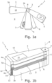
- FIG. 1a, 1b Furniture 1 shown has a vertical rotating column 2 , around which a wedge-shaped bed 3 and optionally, each at different heights Above the bed 3, further wedge-shaped functional elements 4-7 are freely rotatable.
- the bed 3 and the functional elements 4-7 run in a wedge shape towards the rotating column 2 or its vertical axis of rotation 8 and are rotatably mounted on the rotating column 2 at their tapered, possibly rounded or blunt end.
- the rotating column 2 can either be anchored immovably on the floor 9 in order to firmly specify the axis of rotation 8 in the room, or it can be displaceable on the floor 9 in order to be able to position the furniture 1 together with the axis of rotation 8 anywhere in the room.
- Supply lines for example for electricity, network, supply and waste water, etc., can run in the rotating column 2, to which the bed 3 and the individual functional elements are connected as required.
- the bed 3 and the functional elements 4-7 preferably have the same wedge-shaped floor plan.
- the wider bed end 3a facing away from the rotating column 2 expediently forms the head end and the narrower bed end 3b facing the rotating column 2 forms the foot end of the wedge-shaped bed 3.
- the lying surface of the bed 3 is designated 10 and has the shape of a truncated wedge.
- the functional elements can be, from top to bottom, an upper table top 4 for working while standing, a lower table top 5 for working while sitting, and a first and a second bench 6, 7.
- the upper table top 4 can, for example, be designed as a kitchen worktop with electrical sockets and / or with electrical devices, such as an integrated hob 11, which are connected to electrical supply lines of the rotating column 3.
- the lower table top 5 can be used as a dining table and desk and can have electrical interfaces, such as integrated sockets or network plugs, which are connected to corresponding supply lines running in the rotating column.
- the bed 3 stands on the floor 9 with gliders or floor rollers (not shown) on the bottom, which slide or roll on the floor 9 when the bed 3 rotates.
- the functional elements 4-7 have, at their wider end facing away from the rotating column 2, side cheeks 4a-7a with floor rollers 12 on the underside, with which the functional elements 4-7 on the floor 9 stand up and roll on the floor 9 when the functional elements 4-7 turn. If the rotating column 2 has sufficient load-bearing capacity, floor rollers and side bolsters can also be dispensed with.
- the side cheeks 4a-7a or the floor rollers 12 are arranged at different radii around the axis of rotation 8, the side cheek radius being greater the higher the respective functional element located in the furniture.
- the side cheek 4a of the topmost functional element 4 therefore has the largest side cheek radius.
- the side cheek radius of the lowest functional element 7 is larger than the radius of the wider bed end 3a to the axis of rotation 8.
- Fig. 1a the furniture 1 is shown in a fan-shaped open position, in which the bed 3 is rotated into its lying position and the bed 3 and all functional elements 4-7 are rotated relative to one another.
- Fig. 1b The furniture 1 is shown in its completely closed basic position, in which the bed 3 and all functional elements 4-7 are arranged congruently one above the other and together form two flush side fronts 13 of the furniture 1. If at least one of the functional elements 4-7, in particular the lowest functional element 4, is located congruently above the bed 3, this functional element forms a bed box that serves as privacy and dust protection.
- a further functional element can be arranged under the bed 3 in the form of a storage compartment, which is rotatably mounted relative to the bed 3.
- one of the functional elements 4-7 can also be connected to the rotating column 2 in a rotationally fixed manner in order to specify the basic position of the furniture 1.
- the bed 3 and all other functional elements are then arranged congruently below or above this non-rotatable functional element.
- the bed 3 can also have the axis of rotation 8, so that all functional elements 4-7 are rotated relative to the non-rotatable bed 3.
- an additional functional element (not shown) at least 20 cm high can advantageously be arranged between the upper bench 6 and the lower table top 5, which, if turned away accordingly, provides sufficient legroom between the upper bench seat 6 and the lower table top 5.
- wedge-shaped beds 3 instead of just one wedge-shaped bed 3, several wedge-shaped beds 3, each at different heights, can also be rotatably mounted on the rotating column 2. This means that several beds 3 can be stowed away to save space and, if necessary, can be twisted against each other in a fan shape into their respective lying position.
- the furniture 1 can, as in Figs. 1a, 1b shown, arranged as an island in the room or integrated into another piece of furniture, such as a closet.
- the bed 3 and the functional elements 4-7 have a rotation range of 360° available for fanning out, whereas in the latter case the rotation range is significantly restricted by the other furniture.
- Fig. 2 shows another piece of furniture 1' with a wedge-shaped bed 3, one end of the bed (here only as an example the wider bed end 3a) is attached to a rotating part 14 (here only shown as an example as a rotating wall or room divider or rotating shelf), which is fixed around a stationary in the room or vertical axis of rotation 8 which can be moved in space and is rotatably mounted.
- the axis of rotation 8 is preferably designed as a shaft attached to the floor 9 and the ceiling. In the event that the axis of rotation 8 is a hollow shaft, supply lines can run therein, for example to supply power to a reading light provided on the bed 3.
- the wider bed end 3a facing the rotating shelf 14 expediently forms the head end and the narrower bed end 3b facing away from the rotating shelf 14 forms the foot end of the wedge-shaped bed 3.
- the bed 3 and its lying surface 10 have the shape of a truncated wedge.
- the wider bed end 3a is approximately as wide as the rotating shelf 14, but could also be significantly wider or narrower.
- the axis of rotation 8 can also run off-center, for example at a corner of the rotating shelf.
- the bed 3 attached to the rotating shelf 14 serves as a lever arm to make the rotating shelf 14 including the bed 3 easier to rotate around the axis of rotation 8 to be able to rotate.
- the bed 3 can have floor gliders or floor rollers (not shown), at least at its narrower end 3b, which slide or roll on the floor 9 when the bed 3 rotates.
- the bed 3 When not in use, the bed 3 can be turned to a side facing away from the room so that it is not visible from the room and the rotating shelf 14 can be used as a shelf. By turning the rotating shelf 14 further or back, the bed 3 can be turned back into a position of use facing the room.
Landscapes
- Health & Medical Sciences (AREA)
- General Health & Medical Sciences (AREA)
- Nursing (AREA)
- Combinations Of Kitchen Furniture (AREA)
- Tables And Desks Characterized By Structural Shape (AREA)
- Special Chairs (AREA)
Description
- Die Erfindung betrifft ein Möbel mit mindestens einem Bett und mit einer vertikalen Drehachse, um die das mindestens eine Bett drehbar gelagert ist, wobei die Drehachse an einem der beiden Bettenden des Bettes angeordnet ist.
- Ein derartiges Möbel ist beispielsweise durch
DE 20 2013 105344 U1 bekannt geworden. Bei diesem Möbel sind ein Bett und ein Tisch relativ zueinander um eine vertikale Drehwelle verdrehbar gelagert. - Keilförmige Betten sind beispielsweise aus dem Schiffsbau zur Gestaltung von Kojen bekannt. Die Keilform hat den Vorteil, dass Ecken am Fußende eines Bettes, die normalerweise nicht genutzt werden, auch nicht ausgebildet sind. Ein keilförmiges Bett ist am Kopfende breiter als am Fußende. Dies kann raumsparend genutzt werden. Die Form der Liegefläche kann dabei auch nur teilweise einem Keil entsprechen, beispielsweise kann sie die Form eines abgeschnittenen Keils (Keilstumpf), also ohne Keilspitze, aufweisen.
- Ein dreieckiges Bett ist beispielsweise aus der Veröffentlichung "Triangular bed" vom 14.06.2015 gebannt, gefunden im Internet:
URL:https://web.archive.org/web/20160203231341/http:/june-14.com/2015/trianaular-bed/. - Weiter ist aus
GB 2 389 307 A - Der vorliegenden Erfindung liegt demgegenüber die Aufgabe zugrunde, den im Wohnungsbereich zur Verfügung stehenden Raum flexibler und effizienter zu nutzen.
- Diese Aufgabe wird gelöst durch ein Möbel mit den Merkmalen von Anspruch 1. Bei dem Funktionselement kann es sich beispielsweise um eine Arbeits- oder Tischplatte oder um eine Sitzbank handeln.
- Durch die Drehlagerung des Bettes kann der zur Verfügung stehende Raum besser genutzt werden und das Zentrum des Raumes variabel gestaltet werden. Durch die Anordnung der Drehachse am Kopf- oder Fußende des Bettes wird die Hebelwirkung, die sich in Längsausdehnung des Bettes ergibt, genutzt, um das Drehen des Bettes um seine Drehachse zu erleichtern. Die Lagerachse ist dabei im Bereich des Kopf- oder Fußendes angeordnet, d.h., sie muss sich nicht unmittelbar am Kopf- oder Fußende befinden, sondern kann sich auch neben dem Kopf- oder Fußende befinden. Dies kann z.B. der Fall sein, wenn das Bett die Form eines nicht vollständigen Keiles aufweist, bei dem z.B. die Spitze fehlt.
- Für den Fall, dass das Möbel sowohl ein Bett als auch ein Funktionselement, die gegeneinander verdrehbar sind, aufweist, sind das Bett und das Funktionselement bevorzugt auf unterschiedlichen Höhen angeordnet, damit das Bett und das Funktionselement aneinander vorbei gedreht werden können.
- Die Drehachse kann durch eine Drehsäule des Möbels gebildet sein, um die sich das mindestens eine Bett und/oder das mindestens eine Funktionselement drehen. Vorteilhaft sind in der Drehsäule Versorgungsanschlüsse für das Bett oder das Funktionselement integriert, also z.B. Elektrizitäts-, Netzwerk- oder Wasseranschlüsse, was eine große Flexibilität in der Raumnutzung und eine hohe situative Anpassung bedeutet. Die Drehsäule kann entweder im Raum ortsfest angeordnet ("stationäre Drehsäule") oder beliebig im Raum verschoben ("mobile Drehsäule") werden.
- In einer alternativen Ausführungsform der Erfindung weist das mindestens eine Bett die Drehachse auf, um die das mindestens eine Funktionselement drehbar gelagert ist; das Bett mitsamt seiner Drehachse kann entweder im Raum ortsfest angeordnet sein oder beliebig im Raum verschoben werden. In einer anderen alternativen Ausführungsform weist das mindestens eine Funktionselement die Drehachse auf, um das mindestens eine Bett und gegebenenfalls weitere Funktionselemente drehbar gelagert sind; das Funktionselement mitsamt seiner Drehachse kann entweder im Raum ortsfest angeordnet sein oder beliebig im Raum verschoben werden.
- Vorzugsweise ist das mindestens eine Funktionselement oberhalb des mindestens einen Bettes angeordnet, um in einer Grundstellung des Möbels das mindestens eine Bett als Sicht- und Staubschutz vollständig nach oben abzudecken.
- Besonders bevorzugt sind das mindestens eine Bett und alle vorhandenen Funktionselemente in einer Grundstellung des Möbels deckungsgleich übereinander angeordnet, um gemeinsam zwei bündige Seitenfronten des Möbels auszubilden. In einer Liegestellung des Möbels sind dann das Bett und das Funktionselement fächerförmig soweit gegeneinander verdreht, dass die Liegefläche des Bettes nach oben nicht durch das Funktionselement abgedeckt ist.
- Bei vorteilhaften Ausführungsformen der Erfindung weisen das mindestens eine Bett und/oder das mindestens eine Funktionselement Gleiter oder Bodenrollen auf, die beim Drehen des mindestens einen Bettes oder des mindestens einen Funktionselements auf dem Fußboden gleiten oder abrollen. Dabei können die Gleiter oder Bodenrollen in unterschiedlichen Radien um die Drehachse angeordnet sein, wobei vorteilhaft der Radius umso größer ist, je höher das Bett bzw. das jeweilige Funktionselement im Möbel angeordnet ist.
- Weitere Vorteile der Erfindung ergeben sich aus der Beschreibung, den Ansprüchen und der Zeichnung. Ebenso können die vorstehenden genannten und die noch weiter aufgeführten Merkmale je für sich oder zu mehreren in beliebigen Kombinationen Verwendung finden. Die gezeigten und beschriebenen Ausführungsformen sind nicht als abschließende Aufzählung zu verstehen, sondern haben vielmehr beispielhaften Charakter für die Schilderung der Erfindung.
- Es zeigen:
- Fign. 1a, 1
- b ein erfindungsgemäßes Möbel mit einem schwenkbar gelagerten, keilförmigen Bett, das in der in
Fig. 1a gezeigten Draufsicht in einer ausgeschwenkten Liegestellung und in der inFig. 1b gezeigten perspektivischen Schrägansicht in einer Grundstellung gezeigt ist; und - Fig. 2
- ein weiteres, nicht-erfindungsgemäßes Möbel mit einem an einem Drehregal befestigten, keilförmigen Bett in einer perspektivischen Schrägansicht.
- Das in den
Fign. 1a, 1b gezeigte Möbel 1 weist eine vertikale Drehsäule 2 auf, um die herum ein keilförmiges Bett 3 sowie optional, jeweils auf unterschiedlichen Höhen oberhalb des Bettes 3, weitere keilförmige Funktionselemente 4-7 frei drehbar gelagert sind. Das Bett 3 und die Funktionselemente 4-7 laufen in Richtung auf die Drehsäule 2 bzw. auf deren vertikale Drehachse 8 keilförmig zu und sind an ihrem zulaufenden, ggf. abgerundet oder stumpf ausgebildeten Ende an der Drehsäule 2 drehbar gelagert. Die Drehsäule 2 kann entweder unverschiebbar am Fußboden 9 verankert sein, um so die Drehachse 8 im Raum fest vorzugeben, oder aber auf dem Fußboden 9 verschiebbar sein, um so das Möbel 1 samt Drehachse 8 beliebig im Raum positionieren zu können. In der Drehsäule 2 können Versorgungsleitungen, z.B. für Strom, Netzwerk, Zu- und Abwasser etc., verlaufen, an die das Bett 3 und die einzelnen Funktionselemente je nach Bedarf angeschlossen sind. Das Bett 3 und die Funktionselemente 4-7 haben vorzugsweise den gleichen keilförmigen Grundriss. - Zweckmäßigerweise bildet das der Drehsäule 2 abgewandte, breitere Bettende 3a das Kopfende und das der Drehsäule 2 zugewandte, schmalere Bettende 3b das Fußende des keilförmigen Bettes 3. Die Liegefläche des Bettes 3 ist mit 10 bezeichnet und hat die Form eines Keilstumpfes.
- Wie in
Fign. 1a, 1b lediglich beispielhaft gezeigt, kann es sich bei den Funktionselementen, von oben nach unten, um eine obere Tischplatte 4 zum Arbeiten im Stehen, eine untere Tischplatte 5 zum Arbeiten im Sitzen sowie um eine erste und eine zweite Sitzbank 6, 7 handeln. Die obere Tischplatte 4 kann beispielsweise als Küchenarbeitsplatte mit elektrischen Steckdosen und/oder mit elektrischen Geräten, wie einem integrierten Kochfeld 11, ausgebildet sein, die an elektrische Versorgungsleitungen der Drehsäule 3 angeschlossen sind. Die untere Tischplatte 5 kann als Ess- und Schreibtisch genutzt werden und elektrische Schnittstellen, wie z.B. integrierte Steckdosen oder Netzwerkstecker, aufweisen, die an entsprechende, in der Drehsäule verlaufende Versorgungsleitungen angeschlossen sind. - Am breiteren Bettende 3a steht das Bett 3 mit unterseitigen Gleitern oder Bodenrollen (nicht gezeigt) auf dem Fußboden 9 auf, die beim Drehen des Bettes 3 auf dem Fußboden 9 gleiten bzw. abrollen. Die Funktionselemente 4-7 weisen an ihrem der Drehsäule 2 abgewandten, breiteren Ende Seitenwangen 4a-7a mit unterseitigen Bodenrollen 12 auf, mit denen die Funktionselemente 4-7 auf dem Fußboden 9 aufstehen und die beim Drehen der Funktionselemente 4-7 auf dem Fußboden 9 abrollen. Ist die Drehsäule 2 ausreichend tragfähig, kann auf Bodenrollen und Seitenwangen auch verzichtet werden. Um das Bett 3 und die Funktionselemente 4-7 relativ zueinander fächerförmig verdrehen zu können, sind die Seitenwangen 4a-7a bzw. die Bodenrollen 12 in unterschiedlichen Radien um die Drehachse 8 angeordnet, wobei der Seitenwangenradius umso größer ist, je höher sich das jeweilige Funktionselement im Möbel befindet. Die Seitenwange 4a des obersten Funktionselements 4 weist somit den größten Seitenwangenradius auf. Der Seitenwangenradius des untersten Funktionselements 7 ist größer als der Radius des breiteren Bettendes 3a zur Drehachse 8.
- In
Fig. 1a ist das Möbel 1 in einer fächerförmig geöffneten Stellung gezeigt, in der das Bett 3 in seine Liegeposition gedreht sowie das Bett 3 und alle Funktionselemente 4-7 gegeneinander verdreht sind. InFig. 1b ist das Möbel 1 in seiner vollständig geschlossenen Grundstellung gezeigt, in der das Bett 3 und alle Funktionselemente 4-7 deckungsgleich übereinander angeordnet sind und gemeinsam zwei bündige Seitenfronten 13 des Möbels 1 ausbilden. Befindet sich mindestens eines der Funktionselemente 4-7, insbesondere das unterste Funktionselement 4, deckungsgleich oberhalb des Bettes 3, so bildet dieses Funktionselement einen Bettkasten, der als Sicht- und Staubschutz dient. Optional kann unter dem Bett 3 ein weiteres Funktionselement in Form eines Staufaches angeordnet sein, das relativ zu dem Bett 3 drehbar gelagert ist. - Anders als oben beschrieben, kann eines der Funktionselemente 4-7 auch drehfest mit der Drehsäule 2 verbunden sein, um so die Grundstellung des Möbels 1 vorzugeben. In der vollständig geschlossen Grundstellung sind dann das Bett 3 und alle anderen Funktionselemente deckungsgleich unter oder über diesem drehfesten Funktionselement angeordnet. Alternativ kann auch das Bett 3 die Drehachse 8 aufweisen, so dass alle Funktionselemente 4-7 gegenüber dem drehfesten Bett 3 verdreht werden.
- Anders als in
Fign. 1a, 1b gezeigt, kann vorteilhaft zwischen der oberen Sitzbank 6 und der unteren Tischplatte 5 noch ein mindestens 20 cm hohes, weiteres Funktionselement (nicht gezeigt) angeordnet sein, das, wenn entsprechend weit weggedreht, ausreichend Beinfreiheit zwischen der oberen Sitzbank 6 und der unteren Tischplatte 5 freigibt. - Statt nur eines keilförmigen Bettes 3 können an der Drehsäule 2 auch mehrere keilförmige Betten 3, jeweils auf unterschiedlichen Höhen, drehbar gelagert sein. So können mehrere Betten 3 platzsparend verstaut und bei Bedarf fächerförmig gegeneinander in ihre jeweilige Liegeposition verdreht werden.
- Das Möbel 1 kann, wie in
Fign. 1a, 1b gezeigt, als Insel im Raum angeordnet oder aber in ein weiteres Möbel, wie z.B. in einen Wandschrank, integriert sein. Im ersteren Fall steht dem Bett 3 und den Funktionselemente 4-7 ein Drehbereich von 360° zum Auffächern zur Verfügung, wohingegen im letzteren Fall der Drehbereich durch das weitere Möbel deutlich eingeschränkt ist. -
Fig. 2 zeigt ein weiteres Möbel 1' mit einem keilförmigen Bett 3, dessen eines Bettende (hier lediglich beispielhaft das breitere Bettende 3a) an einem Drehteil 14 (hier lediglich beispielhaft als Drehwand bzw. Raumteiler oder Drehregal dargestellt) befestigt ist, welches um eine im Raum ortsfeste oder im Raum verschiebbare, vertikale Drehachse 8 drehbar gelagert ist. Vorzugsweise ist die Drehachse 8 als eine am Fußboden 9 und an der Decke befestigte Welle ausgeführt. Für den Fall, dass die Drehachse 8 eine Hohlwelle ist, können darin Versorgungsleitungen verlaufen, um z.B. eine am Bett 3 vorgesehene Leseleuchte mit Strom zu versorgen. - Zweckmäßigerweise bildet auch hier das dem Drehregal 14 zugewandte, breitere Bettende 3a das Kopfende und das dem Drehregal 14 abgewandte, schmalere Bettende 3b das Fußende des keilförmigen Bettes 3. Das Bett 3 und seine Liegefläche 10 haben die Form eines Keilstumpfes.
- Wie in
Fig. 2 gezeigt, ist das breitere Bettende 3a etwa genauso breit wie das Drehregal 14, könnte aber auch deutlich breiter oder schmaler sein. Statt wie gezeigt in der Mitte des Drehregals 14 kann die Drehachse 8 auch außermittig, z.B. an einer Drehregalecke, verlaufen. Das an dem Drehregal 14 befestigte Bett 3 dient als Hebelarm, um das Drehregal 14 samt Bett 3 leichter um die Drehachse 8 drehen zu können. Optional kann das Bett 3 zumindest an seinem schmaleren Ende 3b Bodengleiter oder Bodenrollen (nicht gezeigt) aufweisen, die beim Drehen des Bettes 3 auf dem Fußboden 9 gleiten bzw. abrollen. - Bei Nichtgebrauch kann das Bett 3 zu einer raumabgewandten Seite gedreht werden, so dass es vom Raum aus nicht sichtbar ist und das Drehregal 14 als Regal genutzt werden kann. Durch Weiter- oder Zurückdrehen des Drehregals 14 kann das Bett 3 wieder in eine raumzugewandte Gebrauchslage gedreht werden.
Claims (12)
- Möbel (1; 1') mit mindestens einem keilförmigen Bett (3), mit mindestens einem keilförmigen Funktionselement (4-7) und mit einer vertikalen Drehachse (8), um die das mindestens eine Bett (3) und/oder das mindestens eine keilförmige Funktionselement (4-7) drehbar gelagert sind, wobei die Drehachse (8) an einem der beiden Bettenden (3a, 3b) des Bettes (3) angeordnet ist,
wobei das mindestens eine Bett (3) und das mindestens eine Funktionselement (4-7) den gleichen keilförmigen Querschnitt aufweisen und wobei in einer Grundstellung des Möbels (1) das mindestens eine Bett (3) und das mindestens eine Funktionselement (4-7) deckungsgleich übereinander angeordnet sind. - Möbel nach Anspruch 1, dadurch gekennzeichnet, dass das mindestens eine Bett (3) und das mindestens eine Funktionselement (4-7) auf unterschiedlichen Höhen angeordnet sind.
- Möbel nach Anspruch 1 oder 2, dadurch gekennzeichnet, dass das mindestens eine Bett (3) und mehrere Funktionselemente (4-7) auf unterschiedlichen Höhen angeordnet und um die Drehachse (8) relativ zueinander drehbar gelagert sind.
- Möbel nach einem der vorhergehenden Ansprüche, dadurch gekennzeichnet, dass die Drehachse (8) durch eine Drehsäule (2) des Möbels (1) gebildet ist.
- Möbel nach Anspruch 4, dadurch gekennzeichnet, dass in der Drehsäule (2) Versorgungsanschlüsse für das mindestens eine Bett (3) oder das mindestens eine Funktionselement (4-7) integriert sind.
- Möbel nach einem der Ansprüche 1 bis 3, dadurch gekennzeichnet, dass das mindestens eine Bett (3) die Drehachse (8) aufweist, um die das mindestens eine Funktionselement (4-7) drehbar gelagert ist, oder dass das mindestens eine Funktionselement die Drehachse (8) aufweist, um die das mindestens eine Bett (3) und gegebenenfalls weitere Funktionselemente drehbar gelagert sind.
- Möbel nach einem der vorhergehenden Ansprüche, dadurch gekennzeichnet, dass das mindestens eine Funktionselement (4-7) oberhalb des mindestens einen Bettes (3) angeordnet ist und in einer Grundstellung des Möbels (1) das mindestens eine Bett (3) vollständig nach oben abdeckt.
- Möbel nach einem der vorhergehenden Ansprüche, dadurch gekennzeichnet, dass in einer Grundstellung des Möbels (1) das mindestens eine Bett (3) und alle Funktionselemente (4-7) deckungsgleich übereinander angeordnet sind.
- Möbel nach einem der vorhergehenden Ansprüche, dadurch gekennzeichnet, dass in einer Liegestellung des Möbels (1) das mindestens eine Bett (3) und das mindestens eine Funktionselement (4-7) fächerförmig gegeneinander verdreht sind.
- Möbel nach einem der vorhergehenden Ansprüche, dadurch gekennzeichnet, dass das mindestens eine Bett (3) und/oder das mindestens eine Funktionselement (4-7) Gleiter oder Bodenrollen (12) aufweisen, die beim Drehen des mindestens einen Bettes (3) oder des mindestens einen Funktionselements (4-7) auf dem Fußboden (9) gleiten oder abrollen.
- Möbel nach Anspruch 10, dadurch gekennzeichnet, dass die Gleiter oder Bodenrollen (12) in unterschiedlichen Radien um die Drehachse (8) angeordnet sind.
- Möbel nach einem der vorhergehenden Ansprüche, dadurch gekennzeichnet, dass die Drehachse (8) im Raum ortsfest angeordnet oder im Raum verschiebbar ist.
Applications Claiming Priority (2)
| Application Number | Priority Date | Filing Date | Title |
|---|---|---|---|
| DE202019105741.6U DE202019105741U1 (de) | 2019-10-17 | 2019-10-17 | Möbel mit einem verdrehbaren, keilförmigen Bett |
| PCT/EP2020/071174 WO2021073789A1 (de) | 2019-10-17 | 2020-07-28 | Möbel mit einem verdrehbaren, keilförmigen bett |
Publications (2)
| Publication Number | Publication Date |
|---|---|
| EP3993669A1 EP3993669A1 (de) | 2022-05-11 |
| EP3993669B1 true EP3993669B1 (de) | 2024-01-31 |
Family
ID=68652320
Family Applications (1)
| Application Number | Title | Priority Date | Filing Date |
|---|---|---|---|
| EP20749832.0A Active EP3993669B1 (de) | 2019-10-17 | 2020-07-28 | Möbel mit einem verdrehbaren, keilförmigen bett |
Country Status (7)
| Country | Link |
|---|---|
| US (1) | US11589680B2 (de) |
| EP (1) | EP3993669B1 (de) |
| JP (1) | JP7214048B2 (de) |
| CN (1) | CN114554911A (de) |
| DE (1) | DE202019105741U1 (de) |
| PL (1) | PL3993669T3 (de) |
| WO (1) | WO2021073789A1 (de) |
Families Citing this family (1)
| Publication number | Priority date | Publication date | Assignee | Title |
|---|---|---|---|---|
| DE202019105741U1 (de) * | 2019-10-17 | 2019-10-31 | Häfele GmbH & Co KG | Möbel mit einem verdrehbaren, keilförmigen Bett |
Citations (1)
| Publication number | Priority date | Publication date | Assignee | Title |
|---|---|---|---|---|
| CN203041391U (zh) * | 2012-12-20 | 2013-07-10 | 张雷 | 一种椅子 |
Family Cites Families (26)
| Publication number | Priority date | Publication date | Assignee | Title |
|---|---|---|---|---|
| US3389411A (en) * | 1967-04-07 | 1968-06-25 | William M. Emery | Cover for foam wedge |
| FR2123783A5 (de) * | 1971-02-01 | 1972-09-15 | Pigeon Daniel | |
| US4360936A (en) * | 1980-08-28 | 1982-11-30 | Keller Halbert J | Pivoting bed |
| US4639960A (en) * | 1985-04-16 | 1987-02-03 | Quillen Jeffrey B | Recliner for medical convalescence |
| US4724558A (en) * | 1986-09-05 | 1988-02-16 | Reiff Jeffrey A | Beach blanket and inflatable chair combination |
| DE8701673U1 (de) | 1987-02-04 | 1987-03-26 | Heerklotz, Siegfried, Dipl.-Ing., 4516 Bissendorf | Klappbett mit Himmel |
| FR2698252A1 (fr) * | 1992-11-20 | 1994-05-27 | Pillard Claude | Meuble-lit. |
| US5448790A (en) * | 1993-04-28 | 1995-09-12 | Saro; Jack H. B. | Selectively arrangeable cushion assembly |
| DE9315634U1 (de) | 1993-10-13 | 1994-03-24 | Orkun, Erki, Dipl.-Ing., Bursa | Klappvorrichtung für ein Schrankbett |
| GB2389307A (en) * | 2002-06-05 | 2003-12-10 | Peter Geoffrey Byfield | Elevated rigid bed frame |
| US6848137B1 (en) * | 2003-08-21 | 2005-02-01 | Christopher A. Barnes | Incline-adjustable air mattress |
| US7415743B2 (en) * | 2004-10-05 | 2008-08-26 | Rubio Horacio C | Inclined bed |
| US7784129B2 (en) * | 2007-12-07 | 2010-08-31 | Russell Javaruski | Recumbent therapeutic mattress support |
| US8181295B1 (en) * | 2009-12-16 | 2012-05-22 | Mallinger Michael R | Adjustable air mattress device |
| CN201617498U (zh) * | 2010-02-25 | 2010-11-03 | 无锡爱睿芯电子有限公司 | 多功能床 |
| CN201894369U (zh) * | 2010-10-08 | 2011-07-13 | 黄泽溥 | 改进后的多功能组合家具 |
| CN102907954A (zh) * | 2012-10-28 | 2013-02-06 | 南通芯迎设计服务有限公司 | 一种扇形床下储物装置 |
| DE202013105344U1 (de) * | 2013-11-23 | 2013-12-02 | Yongkang City Xianing Buliao Co., Ltd. | Ein Mehrzweckbett |
| DE202014001974U1 (de) | 2014-03-01 | 2014-04-08 | Johannesburg GmbH | Einbaumöbel |
| CN205649185U (zh) * | 2016-01-19 | 2016-10-19 | 竹巴 | 一种多功能床头柜 |
| DE202016101880U1 (de) * | 2016-04-11 | 2016-04-27 | Häfele Berlin Gmbh & Co Kg | Beschlag zum lösbaren Verbinden zweier Möbelteile |
| CN106235702B (zh) * | 2016-10-17 | 2018-07-06 | 侯伦元 | 适用于房车的智能化多功能家具 |
| DE202017101015U1 (de) * | 2017-02-23 | 2018-02-20 | Steinpol Central Services Sp.Z.O.O. | Sitzmöbel mit Sitzfunktion und mit Liegefunktion |
| CN208388239U (zh) * | 2018-03-08 | 2019-01-18 | 林圣玉 | 一种伸缩型沙发床及床尾凳的组合家具 |
| US11160398B2 (en) * | 2019-07-15 | 2021-11-02 | King Chan | Pillow systems |
| DE202019105741U1 (de) * | 2019-10-17 | 2019-10-31 | Häfele GmbH & Co KG | Möbel mit einem verdrehbaren, keilförmigen Bett |
-
2019
- 2019-10-17 DE DE202019105741.6U patent/DE202019105741U1/de active Active
-
2020
- 2020-07-28 CN CN202080072550.8A patent/CN114554911A/zh active Pending
- 2020-07-28 JP JP2022522863A patent/JP7214048B2/ja active Active
- 2020-07-28 PL PL20749832.0T patent/PL3993669T3/pl unknown
- 2020-07-28 EP EP20749832.0A patent/EP3993669B1/de active Active
- 2020-07-28 WO PCT/EP2020/071174 patent/WO2021073789A1/de not_active Ceased
-
2022
- 2022-04-14 US US17/659,228 patent/US11589680B2/en active Active
Patent Citations (1)
| Publication number | Priority date | Publication date | Assignee | Title |
|---|---|---|---|---|
| CN203041391U (zh) * | 2012-12-20 | 2013-07-10 | 张雷 | 一种椅子 |
Also Published As
| Publication number | Publication date |
|---|---|
| CN114554911A (zh) | 2022-05-27 |
| JP2022547740A (ja) | 2022-11-15 |
| WO2021073789A1 (de) | 2021-04-22 |
| JP7214048B2 (ja) | 2023-01-27 |
| PL3993669T3 (pl) | 2024-06-17 |
| US11589680B2 (en) | 2023-02-28 |
| DE202019105741U1 (de) | 2019-10-31 |
| US20220232987A1 (en) | 2022-07-28 |
| EP3993669A1 (de) | 2022-05-11 |
Similar Documents
| Publication | Publication Date | Title |
|---|---|---|
| EP3200653B1 (de) | Höhenverstellbarer tisch | |
| EP1534101A1 (de) | TISCH, INSBESONDERE BüRO- UND KONFERENZTISCH | |
| EP3341538A1 (de) | Fächerförmige fahrzeugmarkise | |
| EP3687341A1 (de) | Tischfuss | |
| WO2021073789A1 (de) | Möbel mit einem verdrehbaren, keilförmigen bett | |
| DE19652108B4 (de) | Mehrtischsystem | |
| DE9404456U1 (de) | Auf engem Raum verstaubarer Arbeitsplatz | |
| EP0622043A2 (de) | Duschabtrennung | |
| DE20314289U1 (de) | Tisch mit Mehrfachfunktion | |
| AT384353B (de) | Sockelbeschlag fuer moebel | |
| DE19824734B4 (de) | Liege für ein Fahrzeug nach Art eines Campingfahrzeugs | |
| DE2949019C2 (de) | Transportabler Verkaufsanhänger | |
| DE60024745T2 (de) | Eine herausziehbare Arbeitsplatte enthaltendes Möbelstück, insbesondere für Küchen oder andere Wohnungseinrichtungen | |
| DE102024001984A1 (de) | Wandsystem und Raumanordnung | |
| EP0908116B1 (de) | Tisch mit einer Tischplatte | |
| DE1922048C3 (de) | Möbel mit einem flachen Schrankkasten | |
| DE202005005799U1 (de) | Trennwandelement und Arbeitsplatzanordnung mit diesem | |
| DE29818874U1 (de) | Modularer Tisch | |
| DE202022104085U1 (de) | Möbel | |
| DE10064740B4 (de) | Lagersystem | |
| DE202020103292U1 (de) | Möbelteil sowie Zusammenfassung von zwei oder mehr modulartig gebildeten Möbelteilen | |
| DE10260461A1 (de) | Stützfuß | |
| DE202011004336U1 (de) | Klapptisch | |
| DE20103405U1 (de) | Teleskoptribüne | |
| DE29710029U1 (de) | Sideboard-Arbeitsplatz |
Legal Events
| Date | Code | Title | Description |
|---|---|---|---|
| STAA | Information on the status of an ep patent application or granted ep patent |
Free format text: STATUS: UNKNOWN |
|
| STAA | Information on the status of an ep patent application or granted ep patent |
Free format text: STATUS: THE INTERNATIONAL PUBLICATION HAS BEEN MADE |
|
| PUAI | Public reference made under article 153(3) epc to a published international application that has entered the european phase |
Free format text: ORIGINAL CODE: 0009012 |
|
| STAA | Information on the status of an ep patent application or granted ep patent |
Free format text: STATUS: REQUEST FOR EXAMINATION WAS MADE |
|
| 17P | Request for examination filed |
Effective date: 20220201 |
|
| AK | Designated contracting states |
Kind code of ref document: A1 Designated state(s): AL AT BE BG CH CY CZ DE DK EE ES FI FR GB GR HR HU IE IS IT LI LT LU LV MC MK MT NL NO PL PT RO RS SE SI SK SM TR |
|
| DAV | Request for validation of the european patent (deleted) | ||
| DAX | Request for extension of the european patent (deleted) | ||
| P01 | Opt-out of the competence of the unified patent court (upc) registered |
Effective date: 20230630 |
|
| REG | Reference to a national code |
Ref country code: DE Ref legal event code: R079 Free format text: PREVIOUS MAIN CLASS: A47C0019220000 Ipc: A47C0019200000 Ref country code: DE Ref legal event code: R079 Ref document number: 502020006880 Country of ref document: DE Free format text: PREVIOUS MAIN CLASS: A47C0019220000 Ipc: A47C0019200000 |
|
| GRAP | Despatch of communication of intention to grant a patent |
Free format text: ORIGINAL CODE: EPIDOSNIGR1 |
|
| STAA | Information on the status of an ep patent application or granted ep patent |
Free format text: STATUS: GRANT OF PATENT IS INTENDED |
|
| RIC1 | Information provided on ipc code assigned before grant |
Ipc: A47C 19/22 20060101ALI20230830BHEP Ipc: A47C 19/20 20060101AFI20230830BHEP |
|
| INTG | Intention to grant announced |
Effective date: 20230922 |
|
| GRAS | Grant fee paid |
Free format text: ORIGINAL CODE: EPIDOSNIGR3 |
|
| GRAA | (expected) grant |
Free format text: ORIGINAL CODE: 0009210 |
|
| STAA | Information on the status of an ep patent application or granted ep patent |
Free format text: STATUS: THE PATENT HAS BEEN GRANTED |
|
| AK | Designated contracting states |
Kind code of ref document: B1 Designated state(s): AL AT BE BG CH CY CZ DE DK EE ES FI FR GB GR HR HU IE IS IT LI LT LU LV MC MK MT NL NO PL PT RO RS SE SI SK SM TR |
|
| REG | Reference to a national code |
Ref country code: GB Ref legal event code: FG4D Free format text: NOT ENGLISH Ref country code: CH Ref legal event code: EP |
|
| REG | Reference to a national code |
Ref country code: DE Ref legal event code: R096 Ref document number: 502020006880 Country of ref document: DE |
|
| REG | Reference to a national code |
Ref country code: IE Ref legal event code: FG4D Free format text: LANGUAGE OF EP DOCUMENT: GERMAN |
|
| REG | Reference to a national code |
Ref country code: LT Ref legal event code: MG9D |
|
| REG | Reference to a national code |
Ref country code: NL Ref legal event code: MP Effective date: 20240131 |
|
| PG25 | Lapsed in a contracting state [announced via postgrant information from national office to epo] |
Ref country code: IS Free format text: LAPSE BECAUSE OF FAILURE TO SUBMIT A TRANSLATION OF THE DESCRIPTION OR TO PAY THE FEE WITHIN THE PRESCRIBED TIME-LIMIT Effective date: 20240531 |
|
| PG25 | Lapsed in a contracting state [announced via postgrant information from national office to epo] |
Ref country code: LT Free format text: LAPSE BECAUSE OF FAILURE TO SUBMIT A TRANSLATION OF THE DESCRIPTION OR TO PAY THE FEE WITHIN THE PRESCRIBED TIME-LIMIT Effective date: 20240131 |
|
| PG25 | Lapsed in a contracting state [announced via postgrant information from national office to epo] |
Ref country code: GR Free format text: LAPSE BECAUSE OF FAILURE TO SUBMIT A TRANSLATION OF THE DESCRIPTION OR TO PAY THE FEE WITHIN THE PRESCRIBED TIME-LIMIT Effective date: 20240501 |
|
| PG25 | Lapsed in a contracting state [announced via postgrant information from national office to epo] |
Ref country code: RS Free format text: LAPSE BECAUSE OF FAILURE TO SUBMIT A TRANSLATION OF THE DESCRIPTION OR TO PAY THE FEE WITHIN THE PRESCRIBED TIME-LIMIT Effective date: 20240430 Ref country code: NL Free format text: LAPSE BECAUSE OF FAILURE TO SUBMIT A TRANSLATION OF THE DESCRIPTION OR TO PAY THE FEE WITHIN THE PRESCRIBED TIME-LIMIT Effective date: 20240131 Ref country code: HR Free format text: LAPSE BECAUSE OF FAILURE TO SUBMIT A TRANSLATION OF THE DESCRIPTION OR TO PAY THE FEE WITHIN THE PRESCRIBED TIME-LIMIT Effective date: 20240131 |
|
| PG25 | Lapsed in a contracting state [announced via postgrant information from national office to epo] |
Ref country code: ES Free format text: LAPSE BECAUSE OF FAILURE TO SUBMIT A TRANSLATION OF THE DESCRIPTION OR TO PAY THE FEE WITHIN THE PRESCRIBED TIME-LIMIT Effective date: 20240131 |
|
| PG25 | Lapsed in a contracting state [announced via postgrant information from national office to epo] |
Ref country code: RS Free format text: LAPSE BECAUSE OF FAILURE TO SUBMIT A TRANSLATION OF THE DESCRIPTION OR TO PAY THE FEE WITHIN THE PRESCRIBED TIME-LIMIT Effective date: 20240430 Ref country code: NO Free format text: LAPSE BECAUSE OF FAILURE TO SUBMIT A TRANSLATION OF THE DESCRIPTION OR TO PAY THE FEE WITHIN THE PRESCRIBED TIME-LIMIT Effective date: 20240430 Ref country code: NL Free format text: LAPSE BECAUSE OF FAILURE TO SUBMIT A TRANSLATION OF THE DESCRIPTION OR TO PAY THE FEE WITHIN THE PRESCRIBED TIME-LIMIT Effective date: 20240131 Ref country code: LT Free format text: LAPSE BECAUSE OF FAILURE TO SUBMIT A TRANSLATION OF THE DESCRIPTION OR TO PAY THE FEE WITHIN THE PRESCRIBED TIME-LIMIT Effective date: 20240131 Ref country code: IS Free format text: LAPSE BECAUSE OF FAILURE TO SUBMIT A TRANSLATION OF THE DESCRIPTION OR TO PAY THE FEE WITHIN THE PRESCRIBED TIME-LIMIT Effective date: 20240531 Ref country code: HR Free format text: LAPSE BECAUSE OF FAILURE TO SUBMIT A TRANSLATION OF THE DESCRIPTION OR TO PAY THE FEE WITHIN THE PRESCRIBED TIME-LIMIT Effective date: 20240131 Ref country code: GR Free format text: LAPSE BECAUSE OF FAILURE TO SUBMIT A TRANSLATION OF THE DESCRIPTION OR TO PAY THE FEE WITHIN THE PRESCRIBED TIME-LIMIT Effective date: 20240501 Ref country code: FI Free format text: LAPSE BECAUSE OF FAILURE TO SUBMIT A TRANSLATION OF THE DESCRIPTION OR TO PAY THE FEE WITHIN THE PRESCRIBED TIME-LIMIT Effective date: 20240131 Ref country code: ES Free format text: LAPSE BECAUSE OF FAILURE TO SUBMIT A TRANSLATION OF THE DESCRIPTION OR TO PAY THE FEE WITHIN THE PRESCRIBED TIME-LIMIT Effective date: 20240131 Ref country code: BG Free format text: LAPSE BECAUSE OF FAILURE TO SUBMIT A TRANSLATION OF THE DESCRIPTION OR TO PAY THE FEE WITHIN THE PRESCRIBED TIME-LIMIT Effective date: 20240131 |
|
| PG25 | Lapsed in a contracting state [announced via postgrant information from national office to epo] |
Ref country code: PT Free format text: LAPSE BECAUSE OF FAILURE TO SUBMIT A TRANSLATION OF THE DESCRIPTION OR TO PAY THE FEE WITHIN THE PRESCRIBED TIME-LIMIT Effective date: 20240531 |
|
| PGFP | Annual fee paid to national office [announced via postgrant information from national office to epo] |
Ref country code: PL Payment date: 20240626 Year of fee payment: 5 |
|
| PG25 | Lapsed in a contracting state [announced via postgrant information from national office to epo] |
Ref country code: SE Free format text: LAPSE BECAUSE OF FAILURE TO SUBMIT A TRANSLATION OF THE DESCRIPTION OR TO PAY THE FEE WITHIN THE PRESCRIBED TIME-LIMIT Effective date: 20240131 Ref country code: PT Free format text: LAPSE BECAUSE OF FAILURE TO SUBMIT A TRANSLATION OF THE DESCRIPTION OR TO PAY THE FEE WITHIN THE PRESCRIBED TIME-LIMIT Effective date: 20240531 Ref country code: LV Free format text: LAPSE BECAUSE OF FAILURE TO SUBMIT A TRANSLATION OF THE DESCRIPTION OR TO PAY THE FEE WITHIN THE PRESCRIBED TIME-LIMIT Effective date: 20240131 |
|
| PG25 | Lapsed in a contracting state [announced via postgrant information from national office to epo] |
Ref country code: DK Free format text: LAPSE BECAUSE OF FAILURE TO SUBMIT A TRANSLATION OF THE DESCRIPTION OR TO PAY THE FEE WITHIN THE PRESCRIBED TIME-LIMIT Effective date: 20240131 |
|
| PG25 | Lapsed in a contracting state [announced via postgrant information from national office to epo] |
Ref country code: SM Free format text: LAPSE BECAUSE OF FAILURE TO SUBMIT A TRANSLATION OF THE DESCRIPTION OR TO PAY THE FEE WITHIN THE PRESCRIBED TIME-LIMIT Effective date: 20240131 |
|
| PG25 | Lapsed in a contracting state [announced via postgrant information from national office to epo] |
Ref country code: CZ Free format text: LAPSE BECAUSE OF FAILURE TO SUBMIT A TRANSLATION OF THE DESCRIPTION OR TO PAY THE FEE WITHIN THE PRESCRIBED TIME-LIMIT Effective date: 20240131 Ref country code: EE Free format text: LAPSE BECAUSE OF FAILURE TO SUBMIT A TRANSLATION OF THE DESCRIPTION OR TO PAY THE FEE WITHIN THE PRESCRIBED TIME-LIMIT Effective date: 20240131 |
|
| PG25 | Lapsed in a contracting state [announced via postgrant information from national office to epo] |
Ref country code: SK Free format text: LAPSE BECAUSE OF FAILURE TO SUBMIT A TRANSLATION OF THE DESCRIPTION OR TO PAY THE FEE WITHIN THE PRESCRIBED TIME-LIMIT Effective date: 20240131 |
|
| PG25 | Lapsed in a contracting state [announced via postgrant information from national office to epo] |
Ref country code: SM Free format text: LAPSE BECAUSE OF FAILURE TO SUBMIT A TRANSLATION OF THE DESCRIPTION OR TO PAY THE FEE WITHIN THE PRESCRIBED TIME-LIMIT Effective date: 20240131 Ref country code: SK Free format text: LAPSE BECAUSE OF FAILURE TO SUBMIT A TRANSLATION OF THE DESCRIPTION OR TO PAY THE FEE WITHIN THE PRESCRIBED TIME-LIMIT Effective date: 20240131 Ref country code: RO Free format text: LAPSE BECAUSE OF FAILURE TO SUBMIT A TRANSLATION OF THE DESCRIPTION OR TO PAY THE FEE WITHIN THE PRESCRIBED TIME-LIMIT Effective date: 20240131 Ref country code: EE Free format text: LAPSE BECAUSE OF FAILURE TO SUBMIT A TRANSLATION OF THE DESCRIPTION OR TO PAY THE FEE WITHIN THE PRESCRIBED TIME-LIMIT Effective date: 20240131 Ref country code: DK Free format text: LAPSE BECAUSE OF FAILURE TO SUBMIT A TRANSLATION OF THE DESCRIPTION OR TO PAY THE FEE WITHIN THE PRESCRIBED TIME-LIMIT Effective date: 20240131 Ref country code: CZ Free format text: LAPSE BECAUSE OF FAILURE TO SUBMIT A TRANSLATION OF THE DESCRIPTION OR TO PAY THE FEE WITHIN THE PRESCRIBED TIME-LIMIT Effective date: 20240131 |
|
| REG | Reference to a national code |
Ref country code: DE Ref legal event code: R097 Ref document number: 502020006880 Country of ref document: DE |
|
| PLBE | No opposition filed within time limit |
Free format text: ORIGINAL CODE: 0009261 |
|
| STAA | Information on the status of an ep patent application or granted ep patent |
Free format text: STATUS: NO OPPOSITION FILED WITHIN TIME LIMIT |
|
| 26N | No opposition filed |
Effective date: 20241101 |
|
| PG25 | Lapsed in a contracting state [announced via postgrant information from national office to epo] |
Ref country code: MC Free format text: LAPSE BECAUSE OF FAILURE TO SUBMIT A TRANSLATION OF THE DESCRIPTION OR TO PAY THE FEE WITHIN THE PRESCRIBED TIME-LIMIT Effective date: 20240131 |
|
| PG25 | Lapsed in a contracting state [announced via postgrant information from national office to epo] |
Ref country code: LU Free format text: LAPSE BECAUSE OF NON-PAYMENT OF DUE FEES Effective date: 20240728 |
|
| PG25 | Lapsed in a contracting state [announced via postgrant information from national office to epo] |
Ref country code: LU Free format text: LAPSE BECAUSE OF NON-PAYMENT OF DUE FEES Effective date: 20240728 |
|
| PG25 | Lapsed in a contracting state [announced via postgrant information from national office to epo] |
Ref country code: SI Free format text: LAPSE BECAUSE OF FAILURE TO SUBMIT A TRANSLATION OF THE DESCRIPTION OR TO PAY THE FEE WITHIN THE PRESCRIBED TIME-LIMIT Effective date: 20240131 Ref country code: BE Free format text: LAPSE BECAUSE OF NON-PAYMENT OF DUE FEES Effective date: 20240731 |
|
| PG25 | Lapsed in a contracting state [announced via postgrant information from national office to epo] |
Ref country code: FR Free format text: LAPSE BECAUSE OF NON-PAYMENT OF DUE FEES Effective date: 20240731 |
|
| REG | Reference to a national code |
Ref country code: BE Ref legal event code: MM Effective date: 20240731 |
|
| PG25 | Lapsed in a contracting state [announced via postgrant information from national office to epo] |
Ref country code: IE Free format text: LAPSE BECAUSE OF NON-PAYMENT OF DUE FEES Effective date: 20240728 |
|
| PGFP | Annual fee paid to national office [announced via postgrant information from national office to epo] |
Ref country code: DE Payment date: 20250728 Year of fee payment: 6 |
|
| PGFP | Annual fee paid to national office [announced via postgrant information from national office to epo] |
Ref country code: IT Payment date: 20250731 Year of fee payment: 6 |
|
| PGFP | Annual fee paid to national office [announced via postgrant information from national office to epo] |
Ref country code: GB Payment date: 20250724 Year of fee payment: 6 |
|
| PGFP | Annual fee paid to national office [announced via postgrant information from national office to epo] |
Ref country code: AT Payment date: 20251020 Year of fee payment: 5 |
|
| PGFP | Annual fee paid to national office [announced via postgrant information from national office to epo] |
Ref country code: CH Payment date: 20250801 Year of fee payment: 6 |
|
| PG25 | Lapsed in a contracting state [announced via postgrant information from national office to epo] |
Ref country code: CY Free format text: LAPSE BECAUSE OF FAILURE TO SUBMIT A TRANSLATION OF THE DESCRIPTION OR TO PAY THE FEE WITHIN THE PRESCRIBED TIME-LIMIT; INVALID AB INITIO Effective date: 20200728 |
|
| PG25 | Lapsed in a contracting state [announced via postgrant information from national office to epo] |
Ref country code: HU Free format text: LAPSE BECAUSE OF FAILURE TO SUBMIT A TRANSLATION OF THE DESCRIPTION OR TO PAY THE FEE WITHIN THE PRESCRIBED TIME-LIMIT; INVALID AB INITIO Effective date: 20200728 |