EP3991908A1 - Schweissvorrichtung mit rauchabzugsfunktion - Google Patents
Schweissvorrichtung mit rauchabzugsfunktion Download PDFInfo
- Publication number
- EP3991908A1 EP3991908A1 EP20836764.9A EP20836764A EP3991908A1 EP 3991908 A1 EP3991908 A1 EP 3991908A1 EP 20836764 A EP20836764 A EP 20836764A EP 3991908 A1 EP3991908 A1 EP 3991908A1
- Authority
- EP
- European Patent Office
- Prior art keywords
- welding
- fume
- welding object
- welding apparatus
- hood
- Prior art date
- Legal status (The legal status is an assumption and is not a legal conclusion. Google has not performed a legal analysis and makes no representation as to the accuracy of the status listed.)
- Granted
Links
Images



Classifications
-
- B—PERFORMING OPERATIONS; TRANSPORTING
- B23—MACHINE TOOLS; METAL-WORKING NOT OTHERWISE PROVIDED FOR
- B23K—SOLDERING OR UNSOLDERING; WELDING; CLADDING OR PLATING BY SOLDERING OR WELDING; CUTTING BY APPLYING HEAT LOCALLY, e.g. FLAME CUTTING; WORKING BY LASER BEAM
- B23K26/00—Working by laser beam, e.g. welding, cutting or boring
- B23K26/18—Working by laser beam, e.g. welding, cutting or boring using absorbing layers on the workpiece, e.g. for marking or protecting purposes
-
- B—PERFORMING OPERATIONS; TRANSPORTING
- B23—MACHINE TOOLS; METAL-WORKING NOT OTHERWISE PROVIDED FOR
- B23K—SOLDERING OR UNSOLDERING; WELDING; CLADDING OR PLATING BY SOLDERING OR WELDING; CUTTING BY APPLYING HEAT LOCALLY, e.g. FLAME CUTTING; WORKING BY LASER BEAM
- B23K26/00—Working by laser beam, e.g. welding, cutting or boring
- B23K26/16—Removal of by-products, e.g. particles or vapours produced during treatment of a workpiece
-
- B—PERFORMING OPERATIONS; TRANSPORTING
- B08—CLEANING
- B08B—CLEANING IN GENERAL; PREVENTION OF FOULING IN GENERAL
- B08B15/00—Preventing escape of dirt or fumes from the area where they are produced; Collecting or removing dirt or fumes from that area
- B08B15/02—Preventing escape of dirt or fumes from the area where they are produced; Collecting or removing dirt or fumes from that area using chambers or hoods covering the area
-
- B—PERFORMING OPERATIONS; TRANSPORTING
- B08—CLEANING
- B08B—CLEANING IN GENERAL; PREVENTION OF FOULING IN GENERAL
- B08B15/00—Preventing escape of dirt or fumes from the area where they are produced; Collecting or removing dirt or fumes from that area
- B08B15/04—Preventing escape of dirt or fumes from the area where they are produced; Collecting or removing dirt or fumes from that area from a small area, e.g. a tool
-
- B—PERFORMING OPERATIONS; TRANSPORTING
- B23—MACHINE TOOLS; METAL-WORKING NOT OTHERWISE PROVIDED FOR
- B23K—SOLDERING OR UNSOLDERING; WELDING; CLADDING OR PLATING BY SOLDERING OR WELDING; CUTTING BY APPLYING HEAT LOCALLY, e.g. FLAME CUTTING; WORKING BY LASER BEAM
- B23K26/00—Working by laser beam, e.g. welding, cutting or boring
- B23K26/08—Devices involving relative movement between laser beam and workpiece
- B23K26/083—Devices involving movement of the workpiece in at least one axial direction
- B23K26/0838—Devices involving movement of the workpiece in at least one axial direction by using an endless conveyor belt
-
- B—PERFORMING OPERATIONS; TRANSPORTING
- B23—MACHINE TOOLS; METAL-WORKING NOT OTHERWISE PROVIDED FOR
- B23K—SOLDERING OR UNSOLDERING; WELDING; CLADDING OR PLATING BY SOLDERING OR WELDING; CUTTING BY APPLYING HEAT LOCALLY, e.g. FLAME CUTTING; WORKING BY LASER BEAM
- B23K26/00—Working by laser beam, e.g. welding, cutting or boring
- B23K26/14—Working by laser beam, e.g. welding, cutting or boring using a fluid stream, e.g. a jet of gas, in conjunction with the laser beam; Nozzles therefor
- B23K26/142—Working by laser beam, e.g. welding, cutting or boring using a fluid stream, e.g. a jet of gas, in conjunction with the laser beam; Nozzles therefor for the removal of by-products
-
- B—PERFORMING OPERATIONS; TRANSPORTING
- B23—MACHINE TOOLS; METAL-WORKING NOT OTHERWISE PROVIDED FOR
- B23K—SOLDERING OR UNSOLDERING; WELDING; CLADDING OR PLATING BY SOLDERING OR WELDING; CUTTING BY APPLYING HEAT LOCALLY, e.g. FLAME CUTTING; WORKING BY LASER BEAM
- B23K26/00—Working by laser beam, e.g. welding, cutting or boring
- B23K26/20—Bonding
- B23K26/21—Bonding by welding
-
- B—PERFORMING OPERATIONS; TRANSPORTING
- B23—MACHINE TOOLS; METAL-WORKING NOT OTHERWISE PROVIDED FOR
- B23K—SOLDERING OR UNSOLDERING; WELDING; CLADDING OR PLATING BY SOLDERING OR WELDING; CUTTING BY APPLYING HEAT LOCALLY, e.g. FLAME CUTTING; WORKING BY LASER BEAM
- B23K26/00—Working by laser beam, e.g. welding, cutting or boring
- B23K26/20—Bonding
- B23K26/21—Bonding by welding
- B23K26/24—Seam welding
-
- B—PERFORMING OPERATIONS; TRANSPORTING
- B23—MACHINE TOOLS; METAL-WORKING NOT OTHERWISE PROVIDED FOR
- B23K—SOLDERING OR UNSOLDERING; WELDING; CLADDING OR PLATING BY SOLDERING OR WELDING; CUTTING BY APPLYING HEAT LOCALLY, e.g. FLAME CUTTING; WORKING BY LASER BEAM
- B23K26/00—Working by laser beam, e.g. welding, cutting or boring
- B23K26/70—Auxiliary operations or equipment
-
- B—PERFORMING OPERATIONS; TRANSPORTING
- B23—MACHINE TOOLS; METAL-WORKING NOT OTHERWISE PROVIDED FOR
- B23K—SOLDERING OR UNSOLDERING; WELDING; CLADDING OR PLATING BY SOLDERING OR WELDING; CUTTING BY APPLYING HEAT LOCALLY, e.g. FLAME CUTTING; WORKING BY LASER BEAM
- B23K26/00—Working by laser beam, e.g. welding, cutting or boring
- B23K26/70—Auxiliary operations or equipment
- B23K26/702—Auxiliary equipment
-
- B—PERFORMING OPERATIONS; TRANSPORTING
- B23—MACHINE TOOLS; METAL-WORKING NOT OTHERWISE PROVIDED FOR
- B23K—SOLDERING OR UNSOLDERING; WELDING; CLADDING OR PLATING BY SOLDERING OR WELDING; CUTTING BY APPLYING HEAT LOCALLY, e.g. FLAME CUTTING; WORKING BY LASER BEAM
- B23K2101/00—Articles made by soldering, welding or cutting
- B23K2101/36—Electric or electronic devices
Definitions
- the present disclosure relates to a welding apparatus having a fume elimination function, and more particularly, to a welding apparatus having a fume elimination function, the welding apparatus being able to efficiently eliminate fume generated while a welding object (i.e. an object to be welded) is being welded using a laser.
- a welding object i.e. an object to be welded
- a portion of a welding object e.g., a tab portion provided on a distal end of a battery
- a laser welding apparatus is performed.
- the laser welding apparatus is provided with a separate fume elimination apparatus (i.e., a suction apparatus) able to eliminate fume, such as smoke, steam, or vapor, generated during laser welding, and such a fume elimination apparatus was previously filed as, for example, Korean Patent Application Publication No. 10-2010-0103130 (published on September 27, 2010 ).
- a separate fume elimination apparatus i.e., a suction apparatus
- the fume elimination apparatus of the related art has the shape of a hood disposed to cover at least the entire upper portion of a welding apparatus.
- the hood serves to draw fume generated during welding using vacuum and discharge the fume to the outside.
- a high vacuum pressure i.e., air current having a high flow rate
- air current having a low flow rate is inevitably formed in the vicinity of a welding portion, spaced apart a predetermined distance from the suction nozzle, due to the structure of the hood.
- the present disclosure has been made to solve the above problems, and an object of the present disclosure is to propose a welding apparatus having a fume elimination function, the welding apparatus being able to rapidly and efficiently eliminate fume generated while a welding object is being welded using a laser.
- a welding apparatus including: a body including a stage on which a welding object is placed; a lighting unit emitting light to the welding object so that a welding portion of the welding object placed on the stage is accurately recognizable; a welding unit provided above the body to weld the welding object placed on the stage; and a fume elimination unit including suction nozzles disposed on at least both sides of the welding portion and configured to draw and discharge fume generated during welding of the welding object.
- the stage may include a conveyor belt rotating in one direction by receiving power so that a plurality of welding objects are able to be sequentially welded while being moved in one direction.
- the lighting unit may include a pair of lighting units disposed on at least both sides of the welding object so as to face each other.
- the lighting unit and the suction nozzles may be disposed so as to be integrally movable up and down by an actuator in order to be prevented from interrupting the welding object when the welding object is moved by the conveyor belt.
- the suction nozzles may be disposed above the lighting unit in order to prevent a decrease in an amount of light, emitted from the lighting units toward the welding object, which may occur when the lighting units are covered by the suction nozzles.
- the fume elimination unit may further include a hood disposed above the welding object.
- a blocking plate may be further provided in an inlet of the hood, the blocking plate being configured to create air current on both sides of an interior of the hood.
- the present disclosure having the above-described configuration is advantageous in that fume generated during welding may be rapidly and efficiently eliminated by the suction nozzles disposed on both sides of a welding portion of a welding object.
- welding apparatus 110 body 111: stage 120: lighting unit 130: welding unit 131: hole 133: laser beam unit 140: fume elimination 141: suction nozzle 143: hood 145: inlet 145a: first fume collection passage 145b: second fume passage collection 147: blocking plate M: welding object M1: welding portion
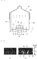
- FIG. 1 is a perspective view illustrating a welding apparatus having a fume elimination function according to the present disclosure
- FIG. 2 is a perspective view illustrating key portions of the welding apparatus having a fume elimination function according to the present disclosure.
- a welding apparatus 100 having a fume elimination function may include a body 110, lighting units 120, a welding unit 130, and a fume elimination unit 140.
- the body 110 forms a main frame of the welding apparatus 100 having a fume elimination function.
- the body 110 may be provided with a stage 111 on which a welding object M (i.e. an object to be welded) is to be placed.
- a welding object M i.e. an object to be welded
- the stage 111 may be provided as a fixed type, but in the present disclosure, the stage 111 may be implemented as a conveyor belt rotating in one direction by receiving power from a motor (not shown) so that a plurality of welding objects M may be sequentially welded while being moved in one direction (i.e., the direction of an arrow in FIG. 1 ).
- stage 111 is implemented as a conveyor belt
- present disclosure is not limited thereto.
- the lighting units 120 may emit light toward the welding object M in order to improve the recognition rate of the accurate location of a welding portion M1, e.g., a tab provided on a distal end, of the welding object M placed on the stage 111.
- a welding portion M1 e.g., a tab provided on a distal end
- a pair of lighting units 120 may be provided on at least both sides of the welding object M with respect to the longitudinal direction of the welding object M such that the lighting units 120 are spaced apart from and face each other.
- the lighting units 120 may be disposed to be movable up and down by an actuator (not shown) in order to prevent the movement of the welding object M on the conveyor belt from being interrupted.
- the present disclosure a case in which the lighting units 120 are disposed to be movable up and down in order to prevent the welding object M from being interrupted while being moved has been described as an example.
- the present disclosure is not limited thereto.
- This configuration of the present disclosure may be modified to a structure in which the lighting units 120 are coupled integrally with the welding unit 130 to be described later, such that the lighting units 120 and the welding unit 130 are disposed to be movable up and down together.
- the lighting units 120 having the above-described configuration may move upward and away from the welding object M in order to prevent interruption with the welding object M. After the welding object M is stopped at a predetermined position for welding, the lighting units 120 may move downward in order to emit light to the welding portion M1 during welding.
- the welding unit 130 is provided above the body 110.
- the welding unit 130 may weld the welding object M, placed on the stage 111, by projecting a laser beam 133 through a hole 131 extending in the top-bottom direction.
- the welding unit 130 may weld the welding portion M1 of the welding object M, e.g., the tab provided on one end of a battery (i.e. the welding object M) in the longitudinal direction of the battery, using the laser beam 133.
- the welding portion M1 of the welding object M e.g., the tab provided on one end of a battery (i.e. the welding object M) in the longitudinal direction of the battery.
- a description of specific operation principle of a welder using a laser beam will be omitted, since the welder using a laser beam is a publicly-known technology.
- the welding unit 130 may include a detector (not shown) able to accurately detect the location of the welding portion M1 when the welding object M is brightly illuminated by the lighting units 120.
- the detector may be implemented as a detection sensor. Since the technology for recognizing the accurate location of the welding portion M1 using the detector as described above is a publicly-known technology, a detailed description thereof will be omitted.
- the fume elimination unit 140 is configured to rapidly draw and discharge welding fume generated during the welding of the welding object M.
- the fume elimination unit 140 may be disposed adjacent to at least both sides of the welding object M.
- the fume elimination unit 140 may include suction nozzles 141 provided on at least both sides of the welding object M so as to be spaced apart therefrom.
- a hood 143 may be disposed above the welding object M. The remaining amount of fume moving upward on air current, instead of being eliminated through the suction nozzles 141, may be eliminated by the hood 143.
- the suction nozzles 141 may be integrally provided so as to extend through the lighting units 120, respectively.
- the suction nozzles 141 may be disposed above the lighting units 120, respectively, in order to prevent a decrease in the amount of light emitted from the lighting units 120 toward the welding object M, which may occur when the lighting units 120 are covered by the suction nozzles 141.
- the suction nozzles 141 may be disposed above the lighting units 120, respectively, so as to efficiently draw the fume generated during the welding of the welding object M.
- the suction nozzles 141 may be connected to the hood 143. Thus, the fume, drawn through the suction nozzles 141, may be upwardly directed and then discharged to an external duct (not shown) through the hood 143.
- the welding apparatus 100 having a fume elimination function according to the present disclosure, configured as described above, may rapidly and efficiently eliminate welding fume generated during the welding of the welding object M using a laser.
- a welding apparatus of the related art has a low flow rate around the welding portion M1 and thus fume generated during welding is not properly discharged.
- the present disclosure may have a high flow rate around the welding portion M1 due to the suction nozzles 141 provided on both sides of the welding portion M1 and thus may eliminate fume generated from the welding portion M1 during welding by directly drawing and discharging the fume.
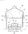
- a blocking plate 147 may be provided in an inlet 145 of the hood 143 in order to generate air current on both sides of the interior of the hood 143. That is, the structure of the blocking plate 147 provided in the central portion of the inlet 145 may define a first fume collection passage 145a and a second fume collection passage 145b on both sides of the inlet 145. Accordingly, the fume, generated from the welding unit 130, may be directly drawn through the first fume collection passage 145a and the second fume collection passage 145b provided on both sides of the hood 143, without passing through the welding portion M1, and then be discharged to the outside.
- the present disclosure is not limited thereto. That is, the hood 143 including the blocking plate 147 may also be applied to the welding apparatus 100 not including the fume elimination unit 140.
Landscapes
- Engineering & Computer Science (AREA)
- Physics & Mathematics (AREA)
- Optics & Photonics (AREA)
- Plasma & Fusion (AREA)
- Mechanical Engineering (AREA)
- Laser Beam Processing (AREA)
Applications Claiming Priority (2)
| Application Number | Priority Date | Filing Date | Title |
|---|---|---|---|
| KR1020190081149A KR102747470B1 (ko) | 2019-07-05 | 2019-07-05 | 흄 제거 기능이 구비된 용접장치 |
| PCT/KR2020/008601 WO2021006534A1 (ko) | 2019-07-05 | 2020-07-01 | 흄 제거 기능이 구비된 용접장치 |
Publications (3)
| Publication Number | Publication Date |
|---|---|
| EP3991908A1 true EP3991908A1 (de) | 2022-05-04 |
| EP3991908A4 EP3991908A4 (de) | 2022-09-07 |
| EP3991908B1 EP3991908B1 (de) | 2026-03-18 |
Family
ID=74115080
Family Applications (1)
| Application Number | Title | Priority Date | Filing Date |
|---|---|---|---|
| EP20836764.9A Active EP3991908B1 (de) | 2019-07-05 | 2020-07-01 | Schweissvorrichtung mit rauchabzugsfunktion |
Country Status (5)
| Country | Link |
|---|---|
| US (1) | US12011780B2 (de) |
| EP (1) | EP3991908B1 (de) |
| KR (1) | KR102747470B1 (de) |
| CN (1) | CN113993654B (de) |
| WO (1) | WO2021006534A1 (de) |
Families Citing this family (2)
| Publication number | Priority date | Publication date | Assignee | Title |
|---|---|---|---|---|
| CN117564592B (zh) * | 2023-12-25 | 2024-08-20 | 山东港基建设集团有限公司 | 一种建筑施工焊接工装及其使用方法 |
| CN118577950B (zh) * | 2024-08-05 | 2024-10-29 | 深圳市欧祺亚实业有限公司 | 一种黄金首饰加工装置 |
Family Cites Families (34)
| Publication number | Priority date | Publication date | Assignee | Title |
|---|---|---|---|---|
| US3761675A (en) * | 1972-01-19 | 1973-09-25 | Hughes Aircraft Co | Material cutting and printing system |
| JPH0751869A (ja) * | 1993-08-13 | 1995-02-28 | Nippei Toyama Corp | 接合線検出装置 |
| JP2795607B2 (ja) * | 1993-12-28 | 1998-09-10 | 三菱電機株式会社 | レーザ加工機 |
| JP2902571B2 (ja) * | 1995-05-12 | 1999-06-07 | 株式会社神戸製鋼所 | 溶接ヒューム吸引除去方法 |
| JP2001321979A (ja) * | 2000-05-12 | 2001-11-20 | Matsushita Electric Ind Co Ltd | レーザー穴加工機の加工粉集塵装置 |
| KR100761737B1 (ko) | 2001-12-12 | 2007-09-28 | 주식회사 포스코 | 용접기에서 발생되는 용접슬라그 및 플라즈마 제거장치 |
| KR100524253B1 (ko) | 2003-05-09 | 2005-10-27 | 김효봉 | 첨두 에너지를 가진 펄스 변조형 Nd-YAG 레이저를 이용한 벨로즈 용접 |
| TWI290500B (en) * | 2004-12-14 | 2007-12-01 | Arima Optoelectronics Corp | Laser dicing apparatus for a silicon wafer and dicing method thereof |
| KR100660221B1 (ko) | 2005-12-24 | 2006-12-21 | 주식회사 포스코 | 맞대기 용접장치 및 그 방법 |
| ITPD20070201A1 (it) * | 2007-06-08 | 2008-12-09 | Helios Technology Societa A Re | Macchina per la rimozione di superfici di semiconduttori, ed in particolare di superfici con circuiti integrati |
| KR100846840B1 (ko) * | 2007-07-25 | 2008-07-16 | 주식회사 나래나노텍 | 복수 쌍의 배터리의 양면을 동시에 용접하기 위한 용접장치 |
| DE102009000256A1 (de) * | 2009-01-15 | 2010-07-22 | Endress + Hauser Conducta Gesellschaft für Mess- und Regeltechnik mbH + Co. KG | Lötdampfabsaugvorrichtung für ein Mikroskop |
| KR101041830B1 (ko) | 2009-03-13 | 2011-06-17 | 아하엠텍(주) | 용접 흄 및 분진 제거 시스템 |
| KR101301138B1 (ko) | 2010-02-11 | 2013-09-03 | 주식회사 엘지화학 | 전극단자의 레이저 용접 장치 및 용접 방법 |
| JP5419807B2 (ja) * | 2010-06-16 | 2014-02-19 | 日立Geニュークリア・エナジー株式会社 | レーザ溶接装置 |
| US9427824B2 (en) * | 2011-06-16 | 2016-08-30 | Preco, Inc. | Laser processing system and method of use |
| KR20130070392A (ko) | 2011-12-19 | 2013-06-27 | 주식회사 성우하이텍 | 레이저 용접용 지그장치 |
| JP2013141669A (ja) * | 2012-01-06 | 2013-07-22 | Nissan Motor Co Ltd | レーザ加工用集塵装置 |
| JP5779152B2 (ja) | 2012-08-02 | 2015-09-16 | 株式会社神戸製鋼所 | 溶接開先部の位置及び形状計測方法 |
| US9440313B2 (en) * | 2013-03-12 | 2016-09-13 | Serenity Data Security, Llc | Hard drive data destroying device |
| US10596659B2 (en) * | 2013-06-24 | 2020-03-24 | Amada America, Inc. | Conveyor system and method for high speed material sheet processing |
| CN105364310A (zh) * | 2015-12-29 | 2016-03-02 | 苏州润昇精密机械有限公司 | 具有烟尘净化功能的激光焊接装置 |
| CN206382705U (zh) * | 2017-01-18 | 2017-08-08 | 郑州博奥激光科技有限责任公司 | 一种激光焊接机 |
| KR102335329B1 (ko) * | 2017-03-07 | 2021-12-03 | 현대자동차 주식회사 | 레이저 용접장치 |
| KR101937360B1 (ko) * | 2017-07-17 | 2019-01-11 | 크루셜머신즈 주식회사 | 레이저 리플로우 장치 |
| CN207026773U (zh) * | 2017-08-10 | 2018-02-23 | 德中(天津)技术发展股份有限公司 | 一种用于激光加工的除尘装置 |
| DE102017215911A1 (de) * | 2017-09-08 | 2019-03-14 | Sauer Gmbh | Laser-Werkzeugmaschine mit Absaugsystem |
| IT201700111570A1 (it) * | 2017-10-05 | 2019-04-05 | Dallan Spa | Apparato e metodo per il taglio al laser o al plasma di pezzi da materiale laminare avvolto in bobina |
| KR101882232B1 (ko) * | 2017-12-06 | 2018-07-26 | 주식회사 제이스텍 | 레이져와 에어흡입공 겸용 레이져가공 스캐너 헤드 |
| JP7422146B2 (ja) * | 2018-10-16 | 2024-01-25 | エレクトロ サイエンティフィック インダストリーズ インコーポレーテッド | レーザ加工システムのためのフレーム及び外側シュラウド |
| CN113165114B (zh) * | 2018-12-03 | 2023-01-24 | 三菱电机株式会社 | 激光加工装置及激光加工方法 |
| US11724336B2 (en) * | 2019-02-06 | 2023-08-15 | Honeywell Federal Manufacturings Technologies, Llc | Apparatus for a laser welding system |
| JP7621732B2 (ja) * | 2019-10-30 | 2025-01-27 | 株式会社ディスコ | レーザー加工装置 |
| JP7426257B2 (ja) * | 2020-02-27 | 2024-02-01 | 本田技研工業株式会社 | レーザ加工装置 |
-
2019
- 2019-07-05 KR KR1020190081149A patent/KR102747470B1/ko active Active
-
2020
- 2020-07-01 WO PCT/KR2020/008601 patent/WO2021006534A1/ko not_active Ceased
- 2020-07-01 CN CN202080045587.1A patent/CN113993654B/zh active Active
- 2020-07-01 US US17/623,782 patent/US12011780B2/en active Active
- 2020-07-01 EP EP20836764.9A patent/EP3991908B1/de active Active
Also Published As
| Publication number | Publication date |
|---|---|
| US12011780B2 (en) | 2024-06-18 |
| EP3991908B1 (de) | 2026-03-18 |
| KR102747470B1 (ko) | 2024-12-27 |
| WO2021006534A1 (ko) | 2021-01-14 |
| CN113993654B (zh) | 2024-03-29 |
| KR20210004552A (ko) | 2021-01-13 |
| US20220241896A1 (en) | 2022-08-04 |
| EP3991908A4 (de) | 2022-09-07 |
| CN113993654A (zh) | 2022-01-28 |
Similar Documents
| Publication | Publication Date | Title |
|---|---|---|
| EP3991908B1 (de) | Schweissvorrichtung mit rauchabzugsfunktion | |
| KR101552562B1 (ko) | 레이저 가공 시스템용 파티클 석션 장치 및 이를 포함한 레이저 가공 시스템 | |
| KR102130694B1 (ko) | 로봇식 레이저 솔기 스텝퍼 | |
| JP6544430B2 (ja) | 質量分析装置 | |
| JP2017100170A (ja) | デブリ回収機構及びレーザ加工装置 | |
| KR200479088Y1 (ko) | 분진 제거 장치 | |
| CN111819027B (zh) | 起火检测方法及起火检测装置 | |
| KR102921742B1 (ko) | 레이저 가공 장치 | |
| CN109792831A (zh) | 在极紫外光源中的靶轨迹量测 | |
| JP2022047808A (ja) | 移動式収穫装置、及び収穫ユニット | |
| JP4933348B2 (ja) | レーザ加工装置 | |
| WO2015068649A1 (ja) | 熱加工機の集塵装置 | |
| JP2006061958A (ja) | プレスブレーキ | |
| CN106312499B (zh) | 一种发射管传送装置 | |
| KR101840669B1 (ko) | 비접촉식 파티클 석션장치 | |
| JP2010099696A (ja) | 切断装置 | |
| US11699569B2 (en) | Ion implanter and particle detection method | |
| US20120076881A1 (en) | Hood for sucking-up fine particles, and a device intended for the laser ablation of a surface layer of a wall and including such a hood | |
| CN117177834A (zh) | 激光裁切装置 | |
| KR100669944B1 (ko) | 이물질 제거와 검출기능을 갖춘 박막성형장치 | |
| KR20230027009A (ko) | 가공 장치 | |
| JP4041974B2 (ja) | 電子線照射装置 | |
| RU2832101C2 (ru) | Устройство лазерной обработки и способ лазерной обработки | |
| JP2000337377A (ja) | ステージ装置 | |
| US20250083252A1 (en) | Laser processing device and laser processing method |
Legal Events
| Date | Code | Title | Description |
|---|---|---|---|
| STAA | Information on the status of an ep patent application or granted ep patent |
Free format text: STATUS: THE INTERNATIONAL PUBLICATION HAS BEEN MADE |
|
| PUAI | Public reference made under article 153(3) epc to a published international application that has entered the european phase |
Free format text: ORIGINAL CODE: 0009012 |
|
| STAA | Information on the status of an ep patent application or granted ep patent |
Free format text: STATUS: REQUEST FOR EXAMINATION WAS MADE |
|
| 17P | Request for examination filed |
Effective date: 20220127 |
|
| AK | Designated contracting states |
Kind code of ref document: A1 Designated state(s): AL AT BE BG CH CY CZ DE DK EE ES FI FR GB GR HR HU IE IS IT LI LT LU LV MC MK MT NL NO PL PT RO RS SE SI SK SM TR |
|
| A4 | Supplementary search report drawn up and despatched |
Effective date: 20220810 |
|
| RIC1 | Information provided on ipc code assigned before grant |
Ipc: B23K 26/21 20140101ALI20220804BHEP Ipc: B23K 26/70 20140101ALI20220804BHEP Ipc: B23K 26/08 20140101ALI20220804BHEP Ipc: B23K 26/142 20140101ALI20220804BHEP Ipc: B23K 26/16 20060101ALI20220804BHEP Ipc: B23K 26/24 20140101ALI20220804BHEP Ipc: B23K 26/18 20060101AFI20220804BHEP |
|
| DAV | Request for validation of the european patent (deleted) | ||
| DAX | Request for extension of the european patent (deleted) | ||
| STAA | Information on the status of an ep patent application or granted ep patent |
Free format text: STATUS: EXAMINATION IS IN PROGRESS |
|
| 17Q | First examination report despatched |
Effective date: 20250515 |
|
| GRAP | Despatch of communication of intention to grant a patent |
Free format text: ORIGINAL CODE: EPIDOSNIGR1 |
|
| STAA | Information on the status of an ep patent application or granted ep patent |
Free format text: STATUS: GRANT OF PATENT IS INTENDED |
|
| INTG | Intention to grant announced |
Effective date: 20251031 |
|
| P01 | Opt-out of the competence of the unified patent court (upc) registered |
Free format text: CASE NUMBER: UPC_APP_0012128_3991908/2025 Effective date: 20251105 |
|
| GRAS | Grant fee paid |
Free format text: ORIGINAL CODE: EPIDOSNIGR3 |
|
| GRAA | (expected) grant |
Free format text: ORIGINAL CODE: 0009210 |
|
| STAA | Information on the status of an ep patent application or granted ep patent |
Free format text: STATUS: THE PATENT HAS BEEN GRANTED |
|
| AK | Designated contracting states |
Kind code of ref document: B1 Designated state(s): AL AT BE BG CH CY CZ DE DK EE ES FI FR GB GR HR HU IE IS IT LI LT LU LV MC MK MT NL NO PL PT RO RS SE SI SK SM TR |
|
| REG | Reference to a national code |
Ref country code: CH Ref legal event code: F10 Free format text: ST27 STATUS EVENT CODE: U-0-0-F10-F00 (AS PROVIDED BY THE NATIONAL OFFICE) Effective date: 20260318 Ref country code: GB Ref legal event code: FG4D |
|
| REG | Reference to a national code |
Ref country code: IE Ref legal event code: FG4D |
|
| REG | Reference to a national code |
Ref country code: DE Ref legal event code: R096 Ref document number: 602020068917 Country of ref document: DE |