EP3990737B1 - Antrieb - Google Patents
Antrieb Download PDFInfo
- Publication number
- EP3990737B1 EP3990737B1 EP20719344.2A EP20719344A EP3990737B1 EP 3990737 B1 EP3990737 B1 EP 3990737B1 EP 20719344 A EP20719344 A EP 20719344A EP 3990737 B1 EP3990737 B1 EP 3990737B1
- Authority
- EP
- European Patent Office
- Prior art keywords
- blocking element
- blocking
- locking device
- housing
- drive according
- Prior art date
- Legal status (The legal status is an assumption and is not a legal conclusion. Google has not performed a legal analysis and makes no representation as to the accuracy of the status listed.)
- Active
Links
Images



Classifications
-
- E—FIXED CONSTRUCTIONS
- E05—LOCKS; KEYS; WINDOW OR DOOR FITTINGS; SAFES
- E05F—DEVICES FOR MOVING WINGS INTO OPEN OR CLOSED POSITION; CHECKS FOR WINGS; WING FITTINGS NOT OTHERWISE PROVIDED FOR, CONCERNED WITH THE FUNCTIONING OF THE WING
- E05F15/00—Power-operated mechanisms for wings
- E05F15/60—Power-operated mechanisms for wings using electrical actuators
- E05F15/603—Power-operated mechanisms for wings using electrical actuators using rotary electromotors
- E05F15/611—Power-operated mechanisms for wings using electrical actuators using rotary electromotors for swinging wings
-
- E—FIXED CONSTRUCTIONS
- E05—LOCKS; KEYS; WINDOW OR DOOR FITTINGS; SAFES
- E05F—DEVICES FOR MOVING WINGS INTO OPEN OR CLOSED POSITION; CHECKS FOR WINGS; WING FITTINGS NOT OTHERWISE PROVIDED FOR, CONCERNED WITH THE FUNCTIONING OF THE WING
- E05F15/00—Power-operated mechanisms for wings
- E05F15/60—Power-operated mechanisms for wings using electrical actuators
- E05F15/603—Power-operated mechanisms for wings using electrical actuators using rotary electromotors
- E05F15/611—Power-operated mechanisms for wings using electrical actuators using rotary electromotors for swinging wings
- E05F15/616—Power-operated mechanisms for wings using electrical actuators using rotary electromotors for swinging wings operated by push-pull mechanisms
- E05F15/622—Power-operated mechanisms for wings using electrical actuators using rotary electromotors for swinging wings operated by push-pull mechanisms using screw-and-nut mechanisms
-
- E—FIXED CONSTRUCTIONS
- E05—LOCKS; KEYS; WINDOW OR DOOR FITTINGS; SAFES
- E05F—DEVICES FOR MOVING WINGS INTO OPEN OR CLOSED POSITION; CHECKS FOR WINGS; WING FITTINGS NOT OTHERWISE PROVIDED FOR, CONCERNED WITH THE FUNCTIONING OF THE WING
- E05F15/00—Power-operated mechanisms for wings
- E05F15/60—Power-operated mechanisms for wings using electrical actuators
- E05F15/603—Power-operated mechanisms for wings using electrical actuators using rotary electromotors
- E05F15/611—Power-operated mechanisms for wings using electrical actuators using rotary electromotors for swinging wings
- E05F15/616—Power-operated mechanisms for wings using electrical actuators using rotary electromotors for swinging wings operated by push-pull mechanisms
- E05F15/619—Power-operated mechanisms for wings using electrical actuators using rotary electromotors for swinging wings operated by push-pull mechanisms using flexible or rigid rack-and-pinion arrangements
-
- E—FIXED CONSTRUCTIONS
- E05—LOCKS; KEYS; WINDOW OR DOOR FITTINGS; SAFES
- E05F—DEVICES FOR MOVING WINGS INTO OPEN OR CLOSED POSITION; CHECKS FOR WINGS; WING FITTINGS NOT OTHERWISE PROVIDED FOR, CONCERNED WITH THE FUNCTIONING OF THE WING
- E05F15/00—Power-operated mechanisms for wings
- E05F15/70—Power-operated mechanisms for wings with automatic actuation
- E05F15/73—Power-operated mechanisms for wings with automatic actuation responsive to movement or presence of persons or objects
-
- E—FIXED CONSTRUCTIONS
- E05—LOCKS; KEYS; WINDOW OR DOOR FITTINGS; SAFES
- E05Y—INDEXING SCHEME ASSOCIATED WITH SUBCLASSES E05D AND E05F, RELATING TO CONSTRUCTION ELEMENTS, ELECTRIC CONTROL, POWER SUPPLY, POWER SIGNAL OR TRANSMISSION, USER INTERFACES, MOUNTING OR COUPLING, DETAILS, ACCESSORIES, AUXILIARY OPERATIONS NOT OTHERWISE PROVIDED FOR, APPLICATION THEREOF
- E05Y2201/00—Constructional elements; Accessories therefor
- E05Y2201/10—Covers; Housings
-
- E—FIXED CONSTRUCTIONS
- E05—LOCKS; KEYS; WINDOW OR DOOR FITTINGS; SAFES
- E05Y—INDEXING SCHEME ASSOCIATED WITH SUBCLASSES E05D AND E05F, RELATING TO CONSTRUCTION ELEMENTS, ELECTRIC CONTROL, POWER SUPPLY, POWER SIGNAL OR TRANSMISSION, USER INTERFACES, MOUNTING OR COUPLING, DETAILS, ACCESSORIES, AUXILIARY OPERATIONS NOT OTHERWISE PROVIDED FOR, APPLICATION THEREOF
- E05Y2201/00—Constructional elements; Accessories therefor
- E05Y2201/20—Brakes; Disengaging means; Holders; Stops; Valves; Accessories therefor
- E05Y2201/218—Holders
- E05Y2201/22—Locks
-
- E—FIXED CONSTRUCTIONS
- E05—LOCKS; KEYS; WINDOW OR DOOR FITTINGS; SAFES
- E05Y—INDEXING SCHEME ASSOCIATED WITH SUBCLASSES E05D AND E05F, RELATING TO CONSTRUCTION ELEMENTS, ELECTRIC CONTROL, POWER SUPPLY, POWER SIGNAL OR TRANSMISSION, USER INTERFACES, MOUNTING OR COUPLING, DETAILS, ACCESSORIES, AUXILIARY OPERATIONS NOT OTHERWISE PROVIDED FOR, APPLICATION THEREOF
- E05Y2201/00—Constructional elements; Accessories therefor
- E05Y2201/20—Brakes; Disengaging means; Holders; Stops; Valves; Accessories therefor
- E05Y2201/23—Actuation thereof
- E05Y2201/244—Actuation thereof by manual operation
-
- E—FIXED CONSTRUCTIONS
- E05—LOCKS; KEYS; WINDOW OR DOOR FITTINGS; SAFES
- E05Y—INDEXING SCHEME ASSOCIATED WITH SUBCLASSES E05D AND E05F, RELATING TO CONSTRUCTION ELEMENTS, ELECTRIC CONTROL, POWER SUPPLY, POWER SIGNAL OR TRANSMISSION, USER INTERFACES, MOUNTING OR COUPLING, DETAILS, ACCESSORIES, AUXILIARY OPERATIONS NOT OTHERWISE PROVIDED FOR, APPLICATION THEREOF
- E05Y2201/00—Constructional elements; Accessories therefor
- E05Y2201/40—Motors; Magnets; Springs; Weights; Accessories therefor
- E05Y2201/404—Function thereof
- E05Y2201/42—Function thereof for locking
-
- E—FIXED CONSTRUCTIONS
- E05—LOCKS; KEYS; WINDOW OR DOOR FITTINGS; SAFES
- E05Y—INDEXING SCHEME ASSOCIATED WITH SUBCLASSES E05D AND E05F, RELATING TO CONSTRUCTION ELEMENTS, ELECTRIC CONTROL, POWER SUPPLY, POWER SIGNAL OR TRANSMISSION, USER INTERFACES, MOUNTING OR COUPLING, DETAILS, ACCESSORIES, AUXILIARY OPERATIONS NOT OTHERWISE PROVIDED FOR, APPLICATION THEREOF
- E05Y2201/00—Constructional elements; Accessories therefor
- E05Y2201/40—Motors; Magnets; Springs; Weights; Accessories therefor
- E05Y2201/43—Motors
- E05Y2201/434—Electromotors; Details thereof
-
- E—FIXED CONSTRUCTIONS
- E05—LOCKS; KEYS; WINDOW OR DOOR FITTINGS; SAFES
- E05Y—INDEXING SCHEME ASSOCIATED WITH SUBCLASSES E05D AND E05F, RELATING TO CONSTRUCTION ELEMENTS, ELECTRIC CONTROL, POWER SUPPLY, POWER SIGNAL OR TRANSMISSION, USER INTERFACES, MOUNTING OR COUPLING, DETAILS, ACCESSORIES, AUXILIARY OPERATIONS NOT OTHERWISE PROVIDED FOR, APPLICATION THEREOF
- E05Y2201/00—Constructional elements; Accessories therefor
- E05Y2201/60—Suspension or transmission members; Accessories therefor
- E05Y2201/622—Suspension or transmission members elements
- E05Y2201/644—Flexible elongated pulling elements
- E05Y2201/656—Chains
-
- E—FIXED CONSTRUCTIONS
- E05—LOCKS; KEYS; WINDOW OR DOOR FITTINGS; SAFES
- E05Y—INDEXING SCHEME ASSOCIATED WITH SUBCLASSES E05D AND E05F, RELATING TO CONSTRUCTION ELEMENTS, ELECTRIC CONTROL, POWER SUPPLY, POWER SIGNAL OR TRANSMISSION, USER INTERFACES, MOUNTING OR COUPLING, DETAILS, ACCESSORIES, AUXILIARY OPERATIONS NOT OTHERWISE PROVIDED FOR, APPLICATION THEREOF
- E05Y2201/00—Constructional elements; Accessories therefor
- E05Y2201/60—Suspension or transmission members; Accessories therefor
- E05Y2201/622—Suspension or transmission members elements
- E05Y2201/676—Transmission of human force
- E05Y2201/68—Handles, cranks
-
- E—FIXED CONSTRUCTIONS
- E05—LOCKS; KEYS; WINDOW OR DOOR FITTINGS; SAFES
- E05Y—INDEXING SCHEME ASSOCIATED WITH SUBCLASSES E05D AND E05F, RELATING TO CONSTRUCTION ELEMENTS, ELECTRIC CONTROL, POWER SUPPLY, POWER SIGNAL OR TRANSMISSION, USER INTERFACES, MOUNTING OR COUPLING, DETAILS, ACCESSORIES, AUXILIARY OPERATIONS NOT OTHERWISE PROVIDED FOR, APPLICATION THEREOF
- E05Y2400/00—Electronic control; Electrical power; Power supply; Power or signal transmission; User interfaces
- E05Y2400/10—Electronic control
- E05Y2400/50—Fault detection
- E05Y2400/502—Fault detection of components
-
- E—FIXED CONSTRUCTIONS
- E05—LOCKS; KEYS; WINDOW OR DOOR FITTINGS; SAFES
- E05Y—INDEXING SCHEME ASSOCIATED WITH SUBCLASSES E05D AND E05F, RELATING TO CONSTRUCTION ELEMENTS, ELECTRIC CONTROL, POWER SUPPLY, POWER SIGNAL OR TRANSMISSION, USER INTERFACES, MOUNTING OR COUPLING, DETAILS, ACCESSORIES, AUXILIARY OPERATIONS NOT OTHERWISE PROVIDED FOR, APPLICATION THEREOF
- E05Y2400/00—Electronic control; Electrical power; Power supply; Power or signal transmission; User interfaces
- E05Y2400/10—Electronic control
- E05Y2400/50—Fault detection
- E05Y2400/504—Fault detection of control, of software
-
- E—FIXED CONSTRUCTIONS
- E05—LOCKS; KEYS; WINDOW OR DOOR FITTINGS; SAFES
- E05Y—INDEXING SCHEME ASSOCIATED WITH SUBCLASSES E05D AND E05F, RELATING TO CONSTRUCTION ELEMENTS, ELECTRIC CONTROL, POWER SUPPLY, POWER SIGNAL OR TRANSMISSION, USER INTERFACES, MOUNTING OR COUPLING, DETAILS, ACCESSORIES, AUXILIARY OPERATIONS NOT OTHERWISE PROVIDED FOR, APPLICATION THEREOF
- E05Y2400/00—Electronic control; Electrical power; Power supply; Power or signal transmission; User interfaces
- E05Y2400/80—User interfaces
- E05Y2400/81—Feedback to user, e.g. tactile
- E05Y2400/818—Visual
- E05Y2400/822—Light emitters, e.g. light emitting diodes [LED]
-
- E—FIXED CONSTRUCTIONS
- E05—LOCKS; KEYS; WINDOW OR DOOR FITTINGS; SAFES
- E05Y—INDEXING SCHEME ASSOCIATED WITH SUBCLASSES E05D AND E05F, RELATING TO CONSTRUCTION ELEMENTS, ELECTRIC CONTROL, POWER SUPPLY, POWER SIGNAL OR TRANSMISSION, USER INTERFACES, MOUNTING OR COUPLING, DETAILS, ACCESSORIES, AUXILIARY OPERATIONS NOT OTHERWISE PROVIDED FOR, APPLICATION THEREOF
- E05Y2400/00—Electronic control; Electrical power; Power supply; Power or signal transmission; User interfaces
- E05Y2400/80—User interfaces
- E05Y2400/85—User input means
- E05Y2400/856—Actuation thereof
- E05Y2400/858—Actuation thereof by body parts, e.g. by feet
-
- E—FIXED CONSTRUCTIONS
- E05—LOCKS; KEYS; WINDOW OR DOOR FITTINGS; SAFES
- E05Y—INDEXING SCHEME ASSOCIATED WITH SUBCLASSES E05D AND E05F, RELATING TO CONSTRUCTION ELEMENTS, ELECTRIC CONTROL, POWER SUPPLY, POWER SIGNAL OR TRANSMISSION, USER INTERFACES, MOUNTING OR COUPLING, DETAILS, ACCESSORIES, AUXILIARY OPERATIONS NOT OTHERWISE PROVIDED FOR, APPLICATION THEREOF
- E05Y2600/00—Mounting or coupling arrangements for elements provided for in this subclass
- E05Y2600/40—Mounting location; Visibility of the elements
- E05Y2600/46—Mounting location; Visibility of the elements in or on the wing
-
- E—FIXED CONSTRUCTIONS
- E05—LOCKS; KEYS; WINDOW OR DOOR FITTINGS; SAFES
- E05Y—INDEXING SCHEME ASSOCIATED WITH SUBCLASSES E05D AND E05F, RELATING TO CONSTRUCTION ELEMENTS, ELECTRIC CONTROL, POWER SUPPLY, POWER SIGNAL OR TRANSMISSION, USER INTERFACES, MOUNTING OR COUPLING, DETAILS, ACCESSORIES, AUXILIARY OPERATIONS NOT OTHERWISE PROVIDED FOR, APPLICATION THEREOF
- E05Y2800/00—Details, accessories and auxiliary operations not otherwise provided for
- E05Y2800/10—Additional functions
- E05Y2800/106—Lighting
-
- E—FIXED CONSTRUCTIONS
- E05—LOCKS; KEYS; WINDOW OR DOOR FITTINGS; SAFES
- E05Y—INDEXING SCHEME ASSOCIATED WITH SUBCLASSES E05D AND E05F, RELATING TO CONSTRUCTION ELEMENTS, ELECTRIC CONTROL, POWER SUPPLY, POWER SIGNAL OR TRANSMISSION, USER INTERFACES, MOUNTING OR COUPLING, DETAILS, ACCESSORIES, AUXILIARY OPERATIONS NOT OTHERWISE PROVIDED FOR, APPLICATION THEREOF
- E05Y2800/00—Details, accessories and auxiliary operations not otherwise provided for
- E05Y2800/26—Form or shape
- E05Y2800/28—Form or shape tubular, annular
-
- E—FIXED CONSTRUCTIONS
- E05—LOCKS; KEYS; WINDOW OR DOOR FITTINGS; SAFES
- E05Y—INDEXING SCHEME ASSOCIATED WITH SUBCLASSES E05D AND E05F, RELATING TO CONSTRUCTION ELEMENTS, ELECTRIC CONTROL, POWER SUPPLY, POWER SIGNAL OR TRANSMISSION, USER INTERFACES, MOUNTING OR COUPLING, DETAILS, ACCESSORIES, AUXILIARY OPERATIONS NOT OTHERWISE PROVIDED FOR, APPLICATION THEREOF
- E05Y2800/00—Details, accessories and auxiliary operations not otherwise provided for
- E05Y2800/40—Physical or chemical protection
- E05Y2800/424—Physical or chemical protection against unintended use, e.g. protection against vandalism or sabotage
- E05Y2800/426—Physical or chemical protection against unintended use, e.g. protection against vandalism or sabotage against unauthorised use, e.g. keys
-
- E—FIXED CONSTRUCTIONS
- E05—LOCKS; KEYS; WINDOW OR DOOR FITTINGS; SAFES
- E05Y—INDEXING SCHEME ASSOCIATED WITH SUBCLASSES E05D AND E05F, RELATING TO CONSTRUCTION ELEMENTS, ELECTRIC CONTROL, POWER SUPPLY, POWER SIGNAL OR TRANSMISSION, USER INTERFACES, MOUNTING OR COUPLING, DETAILS, ACCESSORIES, AUXILIARY OPERATIONS NOT OTHERWISE PROVIDED FOR, APPLICATION THEREOF
- E05Y2800/00—Details, accessories and auxiliary operations not otherwise provided for
- E05Y2800/73—Multiple functions
-
- E—FIXED CONSTRUCTIONS
- E05—LOCKS; KEYS; WINDOW OR DOOR FITTINGS; SAFES
- E05Y—INDEXING SCHEME ASSOCIATED WITH SUBCLASSES E05D AND E05F, RELATING TO CONSTRUCTION ELEMENTS, ELECTRIC CONTROL, POWER SUPPLY, POWER SIGNAL OR TRANSMISSION, USER INTERFACES, MOUNTING OR COUPLING, DETAILS, ACCESSORIES, AUXILIARY OPERATIONS NOT OTHERWISE PROVIDED FOR, APPLICATION THEREOF
- E05Y2900/00—Application of doors, windows, wings or fittings thereof
- E05Y2900/10—Application of doors, windows, wings or fittings thereof for buildings or parts thereof
- E05Y2900/13—Type of wing
- E05Y2900/132—Doors
-
- E—FIXED CONSTRUCTIONS
- E05—LOCKS; KEYS; WINDOW OR DOOR FITTINGS; SAFES
- E05Y—INDEXING SCHEME ASSOCIATED WITH SUBCLASSES E05D AND E05F, RELATING TO CONSTRUCTION ELEMENTS, ELECTRIC CONTROL, POWER SUPPLY, POWER SIGNAL OR TRANSMISSION, USER INTERFACES, MOUNTING OR COUPLING, DETAILS, ACCESSORIES, AUXILIARY OPERATIONS NOT OTHERWISE PROVIDED FOR, APPLICATION THEREOF
- E05Y2900/00—Application of doors, windows, wings or fittings thereof
- E05Y2900/10—Application of doors, windows, wings or fittings thereof for buildings or parts thereof
- E05Y2900/13—Type of wing
- E05Y2900/148—Windows
Definitions
- the invention relates to a drive for a sash of a window or a door, with a housing, an electromotive drive unit for actuating the sash and an electronic control unit for activating the electromotive drive unit.
- the invention relates to a window or a door with such a drive.
- a drive with the features of the preamble of claim 1 is from the document EP 0 586 347 A1 known.
- the invention is based on the object of specifying a drive of the type mentioned at the outset, with which the aforementioned problem is eliminated. It should be ensured in the simplest possible way, even in the event of a malfunction of the electronic control unit or its software, that the drive and thus the window or door can only be actuated if the user has the appropriate authorization. Furthermore, a corresponding window or a corresponding door should be specified.
- the drive according to the invention for a wing of a window or a door comprises a housing, an electromotive drive unit for actuating the wing and an electronic control unit for activating the electromotive drive unit.
- a blocking element is provided which can be displaced between a blocking position in which actuation of the wing is mechanically prevented by blocking the electromotive drive unit, and a release position in which the electromotive drive unit is mechanically released for actuation of the wing.
- a locking device that can be adjusted between a locking state and an unlocking state is provided, which in the locking state holds the blocking element in the blocking position and in the unlocking state enables the blocking element to be moved from the blocking position to the release position, the locking device having an access safeguard so that the locking device only can be adjusted from the locked state to the unlocked state given access authorization.
- a detector connected to the electronic control unit is also provided, which is designed to detect whether the blocking element is in its blocking position, with the drive being designed in such a way that the electromotive drive unit is not activated when the detector is in the blocking position of the blocking element detected.
- the drive remains secured by mechanical protection even in the event of a malfunction of the electronic control unit or its software.
- the protection according to the invention is not only inexpensive, it can also be easily retrofitted. If the blocking element assumes its blocking position, then this is reported to the electronic control unit via the detector, which then prevents the user operates the drive and thus the window or door. In addition, in this position of the blocking element, it is also not possible to actuate the electromotive drive unit mechanically. If the blocking element is moved into its release position, this is reported accordingly by the detector to the electronic control unit, so that the electronic control unit now allows the user to actuate the drive. In order to move the blocking element into its release position, it is first necessary to move the locking device into its unlocked state. Due to access security, however, this adjustment can only be made if access authorization is available.
- the access protection includes a mechanical locking system that can be actuated by a key, in particular a locking cylinder. With a key, access authorization can be easily verified and reliably implemented.
- the locking device comprises a locking section which, in the locking state, engages in a form-fitting manner in an engagement receptacle of the housing, in particular a base plate of the housing, the engagement being released in the unlocked state.
- the locking of the locking device then consists of a locking relative to the housing of the drive.
- the locking device can be adjusted between the locked state and the unlocked state by rotation about an axis of rotation extending in particular parallel to a longitudinal axis of the drive. This is particularly advantageous since access security is provided by a key that is actuated by turning. It is preferred when the locking section extends transversely, in particular perpendicularly, to the axis of rotation and is pivoted into the aforementioned engagement receptacle of the housing when the locking device is rotated.
- the locking device and the blocking element are coupled to one another such that they can rotate about the displacement direction of the blocking element.
- the locking device and the blocking element it is also possible for the locking device and the blocking element to also be firmly coupled to one another in the locking state in the direction of displacement of the blocking element.
- the locking device comprises a coupling section which, in the unlocked state, engages in a form-fitting manner in an engagement receptacle of the blocking element.
- the coupling section also engages in a form-fitting manner in the engagement receptacle of the blocking element in the locking state.
- the locking device is integrated in a cap, in particular an end cap, which is inserted into the housing at the end.
- a cap in particular an end cap, which is inserted into the housing at the end.
- the cap together with the locking device can be pulled out of the housing together with the blocking element when the locking device is in its unlocked state and is prevented from being pulled out of the housing when the locking device is in its locked state.
- the pulled-out position of the cap corresponds to the release position of the blocking element, with the detector being designed to close to the electronic control unit in the pulled-out position of the cap transmit that the blocking element no longer occupies its blocking position, so that activation of the electromotive drive unit is enabled.
- the detector can be designed as a button that can be actuated by moving the blocking element.
- a detector is inexpensive and functionally reliable.
- the button can be mounted on the blocking element, the button being actuated in the blocking position of the blocking element by contact with the housing and/or lying unactuated outside the housing in the release position of the blocking element.
- the electronic control unit is designed to interrupt activation of the electromotive drive unit as soon as the current consumption exceeds a predefinable value. If the electromotive drive unit or a gear thereof is blocked by the blocking element assuming its blocking position, the power consumption increases when the electromotive drive unit is activated by the electronic control unit. As soon as this exceeds the predefinable value, activation of the electromotive drive unit is interrupted by the electronic control unit.
- the electromotive drive unit comprises a spindle gear driven by an electric motor with a spindle and a spindle nut, via which the wing can be actuated. It is provided that the spindle nut of the spindle gear of the electromotive drive unit can be blocked by the blocking element in its blocking position to mechanically prevent actuation of the wing and the spindle nut can be released with a displacement of the blocking element in its release position.
- an input device which is connected to the electronic control unit and has an operating element that can be actuated manually is preferably provided. However, if the blocking element is in its blocking position, the electromotive drive unit is not activated, as explained above.
- the operating element can be activated depending on whether the detector detects the blocked position of the blocking element. It can therefore be provided that the operating element is not active at all, i.e. cannot be actuated effectively at all, as long as the blocking element is in the blocking position. In this context, it can also be provided that the operating element can be backlit depending on whether the detector detects the blocked position of the blocking element. It can therefore be provided that the operating element is not visible at all as long as the blocking element is in the blocking position.
- the input device can also include several operating elements that together form a control panel, the several operating elements being activated and/or backlit differently via the electronic control unit depending on a respective position of the aforementioned spindle nut of the aforementioned spindle gear of the electromotive drive unit.
- the rotational position of the leaf actuated by the drive can be read, and the drive can be operated particularly intuitively.
- the means for detecting proximity can include at least one capacitive sensor with a capacitive measuring field, with the electronic control unit being designed to monitor changes in the capacitive measuring field that occur when a user approaches.
- the housing is preferably designed at the same time as a handle for manual operation of the wing.
- the housing has a rounded shape in cross section to form an undercut.
- the housing can have a base plate, on which the remaining components of the drive are mounted, and a hood, which serves as a protective hood for the drive.
- the window according to the invention or the door according to the invention is characterized in that it is provided with a drive according to the invention.
- the Figures 1 to 8 show a schematic representation of an exemplary embodiment of a drive 10 according to the invention for a sash of a window or a door.
- the drive 10 comprises a housing 12, an electric motor drive unit 14 to open or close the wing, and an electronic control unit 16 to selectively activate the electric motor drive unit 14, in particular to energize it.
- the drive 10 is provided with a blocking element 20 which, relative to the housing 12, between a blocking position in which an actuation of the wing by blocking the electromotive drive unit 14 mechanically prevents will (cf. 2 , 5 and 6 ), and a release position in which the blocking element 20 is pulled out of the housing 10, as will be explained in more detail below, so that the electromotive drive unit 14 is mechanically released for actuating the wing (cf. 4 and 7 ), can be moved.
- a blocking element 20 which, relative to the housing 12, between a blocking position in which an actuation of the wing by blocking the electromotive drive unit 14 mechanically prevents will (cf. 2 , 5 and 6 ), and a release position in which the blocking element 20 is pulled out of the housing 10, as will be explained in more detail below, so that the electromotive drive unit 14 is mechanically released for actuating the wing (cf. 4 and 7 ), can be moved.
- the electric motor drive unit 14 in the present case comprises a spindle gear driven by an electric motor 30 with a spindle 32 and a spindle nut 34.
- the spindle nut 34 of the spindle gear of the electric motor drive unit 14 is mechanically blocked and cannot be operated.
- the spindle nut 34 is released when the blocking element 20 is moved into its release position.
- a locking device 18 which switches between a locking state (cf. figure 5 ) and an unlocked state (cf. Figures 3 and 4 ) is adjustable.
- the locking device 18 is coupled to the blocking element 20 in such a way that it can be pulled out of the housing 10 together with the blocking element 20 in the unlocked state.
- the locked state on the other hand, the locking device 18 and thus the blocking element 20 cannot be pulled out of the housing 10, so that the blocking element 20 is held in the blocking position.
- the adjustment between the two states takes place by rotating the locking device 18 about an axis of rotation which extends parallel to a longitudinal axis of the drive 10 .
- the locking device 18 has a locking section 52 (cf. figure 5 ), which extends transversely, in particular perpendicularly, to the axis of rotation.
- the locking section 52 is pivoted into an engagement receptacle 60 in a base plate 26 of the housing 12 and engages there in a form-fitting manner create a locked state.
- the locking section 52 is disengaged from the engagement receptacle 60, so that the pulling out explained above is possible.
- the locking device 18 For coupling to the blocking element 20, the locking device 18 has a coupling section 62 which, in the unlocked state, engages in a form-fitting manner in an engagement receptacle 64 of the blocking element 20, as can be seen in particular from FIGS 4 , 6 and 7 is evident.
- the locking device 18 and the blocking element 20 are rotatably coupled to one another about the displacement direction of the blocking element 20 via the coupling section 62 and the engagement receptacle 64 and are rigidly coupled to one another in the displacement direction of the blocking element 20 in the unlocked state.
- the locking device 18 is integrated into an end cap 28 which is inserted into the housing 12 at the end in the displacement direction of the blocking element 20 . If the locking device 18 is in the unlocked state, the end cap 28 can be pulled out of the housing 10 together with the locking device 18 and the blocking element 20 . The pulled-out position of the end cap 28 corresponds to the release position of the blocking element 20. If the locking device 18 is in the locking state, this is not possible due to the positive engagement of the locking section 52 in the engagement receptacle 60.
- the locking device 18 is provided with an access safeguard 58, so that the locking device 18 can only be adjusted from the locked state to the unlocked state if access authorization is present.
- the access safeguard 58 consists of a lock cylinder 58 which can be actuated by a key. Thus only a user who has the key can unlock the locking device 18 .
- the drive 10 has a detector 22 which is connected to the electronic control unit 16 and is used to detect whether the blocking element 20 assumes its blocking position. If this is the case, provision is made for the electromotive drive unit 14 not to be activated. The activation of the electromotive drive unit 14 is thus secured not only mechanically via the form fit explained above, but also electrically via a detector signal. If the end cap 28 is in its pulled-out position and thus the blocking element 20 is no longer in its blocking position, the detector 22 reports this to the electronic control unit 16 so that activation of the electromotive drive unit 14 is generally enabled.
- the detector 22 is designed as a button 22 that can be actuated by moving the blocking element 20 and is mounted on the blocking element 20 . If the blocking element 20 assumes its blocking position, the button 22 is pressed or actuated by the housing 12 (cf. 6 ). If, on the other hand, the blocking element 20 assumes its release position, the button 22 is located outside the housing 12 (cf. 7 ) and is no longer pressed.
- means for monitoring the power consumption of the electromotive drive unit 14 can be provided. Activation of the electromotive drive unit 14 can be interrupted by the electronic control unit 16 as soon as the power consumption exceeds a predefinable value. If the electromotive drive unit 14 is blocked with the locking device 18 locked and the blocking element 20 assuming its blocking position due to the form fit of the locking section 52 of the locking device 18 with the housing 12 or the base plate 26, the power consumption of the electromotive drive unit 14 inevitably increases. As soon as this exceeds the specified value, the activation of the drive unit 14 by the electronic control unit 16 is interrupted.
- the drive 10 is provided with a manually operable control panel 24 for its control by a user (cf. 1 and 8th ).
- the control panel 24 can include several operating elements such as buttons or the like, which can be activated and/or backlit differently via the electronic control unit 16 depending on the respective position of the spindle nut 34 of the spindle gear of the electromotive drive unit 14 . It is provided that at least one operating element of the control panel 24 can be activated and/or backlit depending on whether the button 22 is actuated or not actuated.
- the drive 10 can have means for automatic proximity and/or brightness detection in the area of the control panel 24 in order to activate the control panel 24 used for user control.
- the means for recognizing proximity can, for example, comprise means for monitoring changes in a capacitive measuring field generated in the area of the control panel 24 that occur when a user approaches.
- the drive 10 can also include an odometer 36 connected to the electronic control unit 16 for detecting the opening state of the wing and a display device 38 which can be controlled via the electronic control unit 16 for displaying the opening state of the wing.
- a chassis 44 can be assigned to the electric motor 30 .
- the electronic control unit 16 can be arranged on a control circuit board 46 which is mounted in the housing 12 via a holder 48 .
- the control panel 24 can be introduced into the housing 12 via a holder 50 .
- the housing 12 of the drive 10 can also be designed as a handle for manual operation of the wing.
- the housing 12 has a rounded shape in cross section to form an undercut.
- 9 shows an exemplary inventive-SSES window 54 with a drive 10, as is based on the Figures 1 to 8 is described.
- the drive 10 which also serves as a handle, is provided on a wing 56 of the window 54 in the present case.
- the drive 10 ensures redundant protection via the software of the electronic control unit 16 and via the mechanics. It can also be easily retrofitted. Intuitive operation of the drive 10 is possible with the backlighting of operable buttons on the control panel 24 . With the housing 12 of the drive 10, which also serves as a handle, the previously required additional handle for manual operation on the window sash is no longer required.
Landscapes
- Power-Operated Mechanisms For Wings (AREA)
- Lock And Its Accessories (AREA)
Description
- Die Erfindung betrifft einen Antrieb für einen Flügel eines Fensters oder einer Tür, mit einem Gehäuse, einer elektromotorischen Antriebseinheit zur Betätigung des Flügels und einer elektronischen Steuerungseinheit zur Aktivierung der elektromotorischen Antriebseinheit. Zudem betrifft die Erfindung ein Fenster oder eine Tür mit einem solchen Antrieb. Ein Antrieb mit den Merkmalen des Oberbegriffs des Anspruchs 1 ist aus dem Dokument
EP 0 586 347 A1 bekannt. - Antriebe der eingangs genannten Art sind allgemein bekannt. Nachdem über deren elektromotorische Antriebseinheit der Flügel des Fensters oder der Tür automatisch betätigbar ist, bringen sie einen entsprechend höheren Komfort beim Bedienen des Fensters oder der Tür mit sich. Dabei kann eine Zugangssicherung vorgesehen sein, die sicherstellt, dass nur Berechtigte den Antrieb betätigen und damit das Fenster oder die Tür öffnen, verschwenken und/oder schließen können. Bei einer Fehlfunktion der elektronischen Steuerungseinheit bzw. deren Software besteht nun aber die Gefahr, dass die elektromotorische Antriebseinheit gleichwohl aktiviert und damit der Flügel betätigt werden kann.
- Der Erfindung liegt die Aufgabe zugrunde, einen Antrieb der eingangs genannten Art anzugeben, mit dem das zuvor erwähnte Problem beseitigt ist. Dabei soll auf möglichst einfache Weise auch bei einer Fehlfunktion der elektronischen Steuerungseinheit bzw. deren Software gewährleistet sein, dass eine Betätigung des Antriebs und damit des Fensters oder der Tür nur bei entsprechender Berechtigung möglich ist. Ferner soll ein entsprechendes Fenster oder eine entsprechende Tür angegeben werden.
- Erfindungsgemäß wird diese Aufgabe durch einen Antrieb mit den Merkmalen des Anspruchs 1 gelöst. Bevorzugte Ausführungsformen des erfindungsgemäßen Antriebs ergeben sich aus den Unteransprüchen, der Beschreibung sowie der Zeichnung.
- Der erfindungsgemäße Antrieb für einen Flügel eines Fensters oder einer Tür umfasst ein Gehäuse, eine elektromotorische Antriebseinheit zur Betätigung des Flügels und eine elektronische Steuerungseinheit zur Aktivierung der elektromotorischen Antriebseinheit. Es ist ein Blockadeelement vorgesehen, das zwischen einer Blockadestellung, in der eine Betätigung des Flügels durch Blockieren der elektromotorischen Antriebseinheit mechanisch verhindert wird, und einer Freigabestellung, in der die elektromotorische Antriebseinheit zur Betätigung des Flügels mechanisch freigegeben ist, verschiebbar ist. Es ist ferner eine zwischen einem Verriegelungszustand und einem Entriegelungszustand verstellbare Verriegelungseinrichtung vorgesehen, die im Verriegelungszustand das Blockadeelement in der Blockadestellung hält und im Entriegelungszustand ein Verschieben des Blockadeelements aus der Blockadestellung in die Freigabestellung ermöglicht, wobei die Verriegelungseinrichtung eine Zugangssicherung aufweist, so dass die Verriegelungseinrichtung nur bei gegebener Zugangsberechtigung von dem Verriegelungszustand in den Entriegelungszustand verstellbar ist. Es ist darüber hinaus ein mit der elektronischen Steuerungseinheit in Verbindung stehenden Detektor vorgesehen, der dazu ausgelegt ist, zu detektieren, ob das Blockadeelement seine Blockadestellung einnimmt, wobei der Antrieb derart ausgebildet ist, dass eine Aktivierung der elektromotorischen Antriebseinheit unterbleibt, wenn der Detektor die Blockadestellung des Blockadeelements detektiert.
- Aufgrund dieser Ausbildung bleibt der Antrieb auch bei einer Fehlfunktion der elektronischen Steuerungseinheit bzw. deren Software durch eine mechanische Absicherung gesichert. Die erfindungsgemäße Absicherung ist nicht nur kostengünstig, sie ist auch problemlos nachrüstbar. Nimmt das Blockadeelement seine Blockadestellung ein, so wird dies einerseits über den Detektor an die elektronische Steuerungseinheit gemeldet, die daraufhin verhindert, dass der Anwender den Antrieb und damit das Fenster oder die Tür betätigt. Darüber hinaus ist in dieser Stellung des Blockadeelements die Betätigung der elektromotorischen Antriebseinheit auch mechanisch nicht möglich. Wird das Blockadeelement in seine Freigabestellung verschoben, so wird dies entsprechend von dem Detektor an die elektronische Steuerungseinheit gemeldet, so dass es die elektronische Steuerungseinheit dem Anwender nunmehr erlaubt, den Antrieb zu betätigen. Um das Blockadeelement in seine Freigabestellung zu verschieben, ist es zunächst erforderlich, die Verriegelungseinrichtung in ihren Entriegelungszustand zu verstellen. Diese Verstellung kann aufgrund der Zugangssicherung jedoch nur bei vorliegender Zugangsberechtigung vorgenommen werden.
- Die Zugangssicherung umfasst ein durch einen Schlüssel betätigbares mechanisches Schließsystem, insbesondere einen Schließzylinder. Durch einen Schlüssel kann eine Zugangsberechtigung einfach nachgewiesen und funktionssicher realisiert werden.
- Die Verriegelungseinrichtung umfasst einen Verriegelungsabschnitt, der in dem Verriegelungszustand formschlüssig in eine Eingriffsaufnahme des Gehäuses, insbesondere einer Grundplatte des Gehäuses, eingreift, wobei in dem Entriegelungszustand der Eingriff gelöst ist. Die Verriegelung der Verriegelungseinrichtung besteht dann in einer Verriegelung gegenüber dem Gehäuse des Antriebs. Vorzugsweise ist die Verriegelungseinrichtung durch Drehung um eine insbesondere sich parallel zu einer Längsachse des Antriebs erstreckende Drehachse zwischen dem Verriegelungszustand und dem Entriegelungszustand verstellbar. Dies ist insbesondere dann von Vorteil, da die Zugangssicherung durch einen Schlüssel, der durch Drehen betätigt wird, bereitgestellt wird. Dabei ist es bevorzugt, wenn sich der Verriegelungsabschnitt quer, insbesondere senkrecht, zu der Drehachse erstreckt und beim Drehen der Verriegelungseinrichtung in die vorgenannte Eingriffsaufnahme des Gehäuses hinein geschwenkt wird.
- Gemäß einer bevorzugten Ausführungsform ist vorgesehen, dass die Verriegelungseinrichtung und das Blockadeelement um die Verschieberichtung des Blockadeelements drehbar miteinander gekoppelt sind. Alternativ oder zusätzlich kann vorgesehen sein, dass die Verriegelungseinrichtung und das Blockadeelement in dem Entriegelungszustand in Verschieberichtung des Blockadeelements fest miteinander gekoppelt sind. Grundsätzlich ist es auch möglich, dass die Verriegelungseinrichtung und das Blockadeelement zusätzlich auch in dem Verriegelungszustand in Verschieberichtung des Blockadeelements fest miteinander gekoppelt sind.
- Darüber hinaus ist es bevorzugt, wenn die Verriegelungseinrichtung einen Kopplungsabschnitt umfasst, der in dem Entriegelungszustand formschlüssig in eine Eingriffsaufnahme des Blockadeelements eingreift. Entsprechend ist es auch hier möglich, dass er Kopplungsabschnitt zusätzlich auch in dem Verriegelungszustand formschlüssig in die Eingriffsaufnahme des Blockadeelements eingreift.
- Nach einer bevorzugten Ausführungsform der Erfindung ist die Verriegelungseinrichtung in einer stirnseitig in das Gehäuse eingesetzten Kappe, insbesondere Stirnkappe, integriert. Dies ist insbesondere dann von Vorteil, wenn die Kappe samt Verriegelungseinrichtung bei sich in ihrem Entriegelungszustand befindender Verriegelungseinrichtung zusammen mit dem Blockadeelement aus dem Gehäuse herausziehbar und bei sich in ihrem Verriegelungszustand befindender Verriegelungseinrichtung an einem Herausziehen aus dem Gehäuse gehindert ist. Dabei ist es bevorzugt, wenn die herausgezogene Position der Kappe der Freigabestellung des Blockadeelements entspricht, wobei der Detektor dazu ausgelegt ist, in der herausgezogenen Position der Kappe der elektronischen Steuerungseinheit zu übermitteln, dass das Blockadeelement nicht mehr seine Blockadestellung einnimmt, so dass eine Aktivierung der elektromotorischen Antriebseinheit freigegeben ist.
- Der Detektor kann als ein durch das Verschieben des Blockadeelements betätigbarer Taster ausgebildet sein. Ein derartiger Detektor ist kostengünstig und funktionssicher. Insbesondere kann der Taster an dem Blockadeelement montiert sein, wobei der Taster in der Blockadestellung des Blockadeelements durch Anlage an dem Gehäuse betätigt wird und/oder in der Freigabestellung des Blockadeelements unbetätigt außerhalb des Gehäuses liegt.
- Von Vorteil ist insbesondere auch, wenn Mittel zur Überwachung der Stromaufnahme der elektromotorischen Antriebseinheit vorgesehen sind und die elektronische Steuerungseinheit dazu ausgelegt ist, eine Aktivierung der elektromotorischen Antriebseinheit zu unterbrechen, sobald die Stromaufnahme einen vorgebbaren Wert überschreitet. Ist die elektromotorische Antriebseinheit bzw. ein Getriebe hiervon durch das seine Blockadestellung einnehmende Blockadeelement blockiert, so steigt im Fall einer Aktivierung der elektromotorischen Antriebseinheit durch die elektronische Steuerungseinheit die Stromaufnahme an. Sobald diese den vorgebbaren Wert überschreitet, wird die Aktivierung der elektromotorischen Antriebseinheit durch die elektronische Steuerungseinheit unterbrochen.
- Gemäß dem erfindungsgemäßen Antrieb umfasst die elektromotorische Antriebseinheit ein mittels eines Elektromotors angetriebenes Spindelgetriebe mit einer Spindel und einer Spindelmutter, über das der Flügel betätigbar ist. Dabei ist vorgesehen, dass durch das Blockadeelement in dessen Blockadestellung zum mechanischen Verhindern einer Betätigung des Flügels die Spindelmutter des Spindelgetriebes der elektromotorischen Antriebseinheit blockierbar und mit einer Verschiebung des Blockadeelements in dessen Freigabestellung die Spindelmutter freigebbar ist.
- Bevorzugt ist zur Aktivierung der elektromotorischen Antriebseinheit durch die elektronische Steuerungseinheit eine mit der elektronischen Steuerungseinheit verbundene Eingabeeinrichtung mit einem manuell betätigbaren Bedienelement vorgesehen. Befindet sich das Blockadeelement in seiner Blockadestellung, unterbleibt eine Aktivierung der elektromotorischen Antriebseinheit jedoch, wie es vorstehend erläutert ist.
- Insbesondere ist das Bedienelement in Abhängigkeit davon, ob der Detektor die Blockadestellung des Blockadeelements detektiert, aktivierbar. Es kann also vorgesehen sein, dass das Bedienelement überhaupt nicht aktiv ist, d.h. überhaupt nicht wirksam betätigt werden kann, solange sich das Blockadeelement in der Blockadestellung befindet. In diesem Zusammenhang kann auch vorgesehen sein, dass das Bedienelement in Abhängigkeit davon, ob der Detektor die Blockadestellung des Blockadeelements detektiert, hinterleuchtbar ist. Es kann also vorgesehen sein, dass das Bedienelement überhaupt nicht sichtbar ist, solange sich das Blockadeelement in der Blockadestellung befindet.
- Die Eingabeeinrichtung kann auch mehrere Bedienelemente umfassen, die gemeinsam ein Bedienfeld bilden, wobei die mehreren Bedienelemente über die elektronische Steuerungseinheit in Abhängigkeit von einer jeweiligen Position der vorgenannten Spindelmutter des vorgenannten Spindelgetriebes der elektromotorischen Antriebseinheit unterschiedlich aktivierbar und/oder hinterleuchtbar sind. Hierdurch ist die Drehposition des von dem Antrieb betätigten Flügels ablesbar, und der Antrieb ist besonders intuitiv bedienbar.
- Gemäß einer weiteren vorteilhaften Ausführungsform des erfindungsgemäßen Antriebs sind Mittel zur automatischen Näherungs- und/oder Helligkeitserkennung vorgesehen, um die Eingabeeinrichtung zu aktivieren. Dabei können die Mittel zur Näherungserkennung wenigstens einen kapazitiven Sensor mit einem kapazitiven Messfeld umfassen, wobei die elektronische Steuerungseinheit dazu ausgelegt ist, sich bei einer Annäherung eines Anwenders ergebende Änderungen des kapazitiven Messfeldes zu überwachen.
- Das Gehäuse ist bevorzugt gleichzeitig als Griff zur manuellen Betätigung des Flügels ausgeführt. Vorteilhafterweise besitzt das Gehäuse dabei im Querschnitt zur Bildung eines Hinterschnitts eine gerundete Form.
- Darüber hinaus kann das Gehäuse eine Grundplatte, auf der die übrigen Bestandteile des Antriebs montiert sind, und eine Haube, die als Schutzhaube für den Antrieb dient, aufweisen.
- Das erfindungsgemäße Fenster oder die erfindungsgemäße Tür zeichnen sich dadurch aus, dass es bzw. sie mit einem erfindungsgemäßen Antrieb versehen ist.
- Die Erfindung wird im Folgenden anhand von Ausführungsbeispielen unter Bezugnahme auf die Zeichnung näher erläutert; in dieser zeigen:
- Fig. 1
- eine schematische Seitenansicht einer beispielhaften Ausführungsform eines erfindungsgemäßen Antriebs mit einem Gehäuse,
- Fig. 2
- eine schematische Längsschnittdarstellung des Antriebs gemäß
Fig. 1 , - Fig. 3
- eine schematische, perspektivische Ansicht eines mit einer Stirnkappe versehenen stirnseitigen Endes des Antriebs gemäß
Fig. 1 , wobei die Stirnkappe mit einer darin integrierten Verriegelungseinrichtung aus dem Gehäuse herausgezogen ist, - Fig. 4
- eine der
Fig. 3 entsprechende Darstellung, wobei die Stirnkappe und das Gehäuse jedoch weggelassen sind und ein Blockadeelement sichtbar ist, - Fig. 5
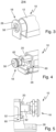
- eine schematische Seitenansicht der Verriegelungseinrichtung gemäß den
Fig. 3 und 4 in einer nicht herausgezogenen Position, - Fig. 6
- eine schematische, perspektivische Ansicht des stirnseitigen Endes des Antriebs gemäß den
Fig. 3 bis 5 , wobei das Blockadeelement eine Blockadestellung einnimmt, - Fig. 7
- eine der
Fig. 6 entsprechende Darstellung, wobei das Blockadeelement eine Freigabestellung einnimmt, - Fig. 8
- eine schematische, perspektivische Gesamtansicht des Antriebs gemäß
Fig. 1 , und - Fig. 9
- eine schematische, perspektivische Ansicht eines beispielhaften erfindungsgemäßen Fensters mit einem Antrieb gemäß
Fig. 1 . - Die
Fig. 1 bis 8 zeigen in schematischer Darstellung eine beispielhafte Ausführungsform eines erfindungsgemäßen Antriebs 10 für einen Flügel eines Fensters oder einer Tür. Der Antrieb 10 umfasst ein Gehäuse 12, eine elektromotorische Antriebseinheit 14, um den Flügel zu öffnen oder zu schließen, und eine elektronische Steuerungseinheit 16, um die elektromotorische Antriebseinheit 14 wahlweise zu aktivieren, insbesondere zu bestromen. - Zudem ist der Antrieb 10 mit einem Blockadeelement 20 versehen, das relativ zum Gehäuse 12 zwischen einer Blockadestellung, in der eine Betätigung des Flügels durch Blockieren der elektromotorischen Antriebseinheit 14 mechanisch verhindert wird (vgl.
Fig. 2 ,5 und6 ), und einer Freigabestellung, in der das Blockadeelement 20 aus dem Gehäuse 10 herausgezogen ist, wie nachstehend noch näher erläutert ist, so dass die elektromotorische Antriebseinheit 14 zur Betätigung des Flügels mechanisch freigegeben ist (vgl.Fig. 4 und7 ), verschiebbar ist. - Wie aus der
Fig. 2 ersichtlich, umfasst die elektromotorische Antriebseinheit 14 im vorliegenden Fall ein mittels eines Elektromotors 30 angetriebenes Spindelgetriebe mit einer Spindel 32 und einer Spindelmutter 34. Wenn sich das Blockadeelement 20 in seiner Blockadestellung befindet, ist die Spindelmutter 34 des Spindelgetriebes der elektromotorischen Antriebseinheit 14 mechanisch blockiert, und kann nicht betätigt werden. Dagegen wird die Spindelmutter 34 freigegeben, wenn das Blockadeelement 20 in seine Freigabestellung verschoben wird. - Darüber hinaus ist eine Verriegelungseinrichtung 18 vorgesehen, die zwischen einem Verriegelungszustand (vgl.
Fig. 5 ) und einem Entriegelungszustand (vgl.Fig. 3 und 4 ) verstellbar ist. Die Verriegelungseinrichtung 18 ist derart mit dem Blockadeelement 20 gekoppelt, dass sie in dem Entriegelungszustand gemeinsam mit dem Blockadeelement 20 aus dem Gehäuse 10 herausziehbar ist. In dem Verriegelungszustand hingegen kann die Verriegelungseinrichtung 18 und damit das Blockadeelement 20 nicht aus dem Gehäuse 10 herausgezogen werden, so dass das Blockadeelement 20 in der Blockadestellung gehalten wird. - Die Verstellung zwischen den beiden Zuständen erfolgt dabei durch Drehung der Verriegelungseinrichtung 18 um eine Drehachse, die sich parallel zu einer Längsachse des Antriebs 10 erstreckt. Insbesondere besitzt die Verriegelungseinrichtung 18 einen Verriegelungsabschnitt 52 (vgl.
Fig. 5 ), der sich quer, insbesondere senkrecht, zu der Drehachse erstreckt. Der Verriegelungsabschnitt 52 wird beim Drehen der Verriegelungseinrichtung 18 aus dem Entriegelungszustand in den Verriegelungszustand in eine Eingriffsaufnahme 60 in einer Grundplatte 26 des Gehäuses 12 hinein geschwenkt wird und greift dort formschlüssig ein, um den Verriegelungszustand herzustellen. Im Entriegelungszustand hingegen ist der Verriegelungsabschnitt 52 außer Eingriff mit der Eingriffsaufnahme 60, so dass das vorstehend erläuterte Herausziehen möglich ist. - Zur Kopplung mit dem Blockadeelement 20 weist die Verriegelungseinrichtung 18 einen Kopplungsabschnitt 62 auf, der in dem Entriegelungszustand formschlüssig in eine Eingriffsaufnahme 64 des Blockadeelements 20 eingreift, wie es insbesondere aus den
Fig. 4 ,6 und 7 ersichtlich ist. Über den Kopplungsabschnitt 62 und die Eingriffsaufnahme 64 sind die Verriegelungseinrichtung 18 und das Blockadeelement 20 um die Verschieberichtung des Blockadeelements 20 drehbar miteinander gekoppelt und in dem Entriegelungszustand in Verschieberichtung des Blockadeelements 20 fest miteinander gekoppelt. - Wie insbesondere der
Fig. 3 entnehmbar ist, ist die Verriegelungseinrichtung 18 in eine Stirnkappe 28 integriert, die in Verschieberichtung des Blockadeelements 20 stirnseitig in das Gehäuse 12 eingesetzt ist. Wenn sich die Verriegelungseinrichtung 18 in dem Entriegelungszustand befindet, kann die Stirnkappe 28 gemeinsam mit der Verriegelungseinrichtung 18 und dem Blockadeelement 20 aus dem Gehäuse 10 herausgezogen werden. Die herausgezogene Position der Stirnkappe 28 entspricht dabei der Freigabestellung des Blockadeelements 20. Befindet sich die Verriegelungseinrichtung 18 in dem Verriegelungszustand, ist dies aufgrund des formschlüssigen Eingriffs des Verriegelungsabschnitts 52 in die Eingriffsaufnahme 60 nicht möglich. - Die Verriegelungseinrichtung 18 ist mit einer Zugangssicherung 58 versehen, so dass die Verriegelungseinrichtung 18 nur bei Vorliegen einer Zugangsberechtigung von dem Verriegelungszustand in den Entriegelungszustand verstellbar ist. Die Zugangssicherung 58 besteht vorliegend in einem Schließzylinder 58, der durch einen Schlüssel betätigbar ist. Somit kann nur ein Anwender, der den Schlüssel besitzt, die Verriegelungseinrichtung 18 entriegeln.
- Ohne Schlüssel ist es nicht möglich, den Antrieb 10 zu betätigen und den Flügel in Öffnungs- oder Schließrichtung zu verschwenken. Ist ein Anwender also nicht berechtigt, bleibt der durch den Verriegelungsabschnitt 52 der Verriegelungseinrichtung 18 bewirkte Formschluss mit dem Gehäuse 12 bzw. der Grundplatte 26 aufrechterhalten. Die Stirnkappe 28 und der seine Blockadestellung einnehmende Blockadeschieber 20 können nicht aus dem Gehäuse 12 herausgezogen werden, d.h. eine Betätigung des Flügels wird durch Blockieren der elektromotorischen Antriebseinheit 14 mechanisch verhindert.
- Darüber hinaus besitzt der Antrieb 10 einen Detektor 22, der mit der elektronischen Steuerungseinheit 16 verbunden ist und dazu verwendet wird, zu detektieren, ob das Blockadeelement 20 seine Blockadestellung einnimmt. Falls dies der Fall ist, ist vorgesehen, dass eine Aktivierung der elektromotorischen Antriebseinheit 14 unterbleibt. Die Aktivierung der elektromotorischen Antriebseinheit 14 ist damit nicht nur mechanisch über den vorstehend erläuterten Formschluss gesichert, sondern auch elektrisch über ein Detektorsignal. Nimmt die Stirnkappe 28 ihre herausgezogene Position und damit das Blockadeelement 20 nicht mehr seine Blockadestellung ein, teilt der Detektor 22 dies entsprechend der elektronischen Steuerungseinheit 16 mit, so dass eine Aktivierung der elektromotorischen Antriebseinheit 14 grundsätzlich freigegeben wird.
- Vorliegend ist der Detektor 22 als ein durch das Verschieben des Blockadeelements 20 betätigbarer Taster 22 ausgebildet, der an dem Blockadeelement 20 montiert ist. Nimmt das Blockadeelement 20 seine Blockadestellung ein, wird der Taster 22 durch das Gehäuse 12 gedrückt bzw. betätigt (vgl.
Fig. 6 ). Nimmt das Blockadeelement 20 hingegen seine Freigabestellung ein, liegt der Taster 22 außerhalb des Gehäuses 12 (vgl.Fig. 7 ) und wird nicht mehr gedrückt. - Darüber hinaus können Mittel zur Überwachung der Stromaufnahme der elektromotorischen Antriebseinheit 14 vorgesehen sein. Dabei kann eine Aktivierung der elektromotorischen Antriebseinheit 14 durch die elektronische Steuerungseinheit 16 unterbrechbar sein, sobald die Stromaufnahme einen vorgebbaren Wert überschreitet. Wird die elektromotorische Antriebseinheit 14 bei verriegelter Verriegelungseinrichtung 18 und seine Blockadestellung einnehmendem Blockadeelement 20 durch den Formschluss des Verriegelungsabschnitts 52 der Verriegelungseinrichtung 18 mit dem Gehäuse 12 bzw. der Grundplatte 26 blockiert, so steigt die Stromaufnahme der elektromotorischen Antriebseinheit 14 zwangsläufig an. Sobald diese den vorgegebenen Wert überschreitet, wird die Ansteuerung der Antriebseinheit 14 durch die elektronische Steuerungseinheit 16 unterbrochen.
- Der Antrieb 10 ist zu dessen Steuerung durch einen Anwender mit einem manuell betätigbaren Bedienfeld 24 versehen (vgl.
Fig. 1 und8 ). Das Bedienfeld 24 kann mehrere Bedienelemente wie Tasten oder dergleichen umfassen, die über die elektronische Steuerungseinheit 16 in Abhängigkeit von der jeweiligen Position der Spindelmutter 34 des Spindelgetriebes der elektromotorischen Antriebseinheit 14 unterschiedlich aktivierbar und/oder hinterleuchtbar sind. Dabei ist vorgesehen, dass wenigstens ein Bedienelement des Bedienfeldes 24 in Abhängigkeit von einer jeweiligen Betätigung oder Nichtbetätigung des Tasters 22 aktivierbar und/oder hinterleuchtbar ist. - Überdies kann der Antrieb 10 mit Mitteln zur automatischen Näherungs- und/oder Helligkeitserkennung im Bereich des Bedienfeldes 24 aufweisen, um das der Anwendersteuerung dienende Bedienfeld 24 zu aktivieren. Dabei können die Mittel zur Näherungserkennung beispielsweise Mittel zur Überwachung von sich bei einer jeweiligen Annäherung eines Anwenders ergebenden Änderungen eines im Bereich des Bedienfeldes 24 erzeugten kapazitiven Messfeldes umfassen.
- Wie insbesondere aus den
Fig. 1 und 2 ersichtlich, kann der Antrieb 10 zudem einen mit der elektronischen Steuerungseinheit 16 in Verbindung stehenden Wegmesser 36 zur Erfassung des Öffnungszustands des Flügels und eine über die elektronische Steuerungseinheit 16 ansteuerbare Anzeigeeinrichtung 38 zur Anzeige des Öffnungszustands des Flügels umfassen. - Dem Elektromotor 30 kann ein Chassis 44 zugeordnet sein. Die elektronische Steuerungseinheit 16 kann auf einer Steuerungsplatine 46 angeordnet sein, die über einen Halter 48 im Gehäuse 12 montiert ist. Das Bedienfeld 24 kann über einen Halter 50 in das Gehäuse 12 eingebracht sein.
- Wie insbesondere aus den
Fig. 8 und 9 ersichtlich, kann das Gehäuse 12 des Antriebs 10 gleichzeitig als Griff zur manuellen Betätigung des Flügels ausgeführt sein. Dabei besitzt das Gehäuse 12 hierzu im Querschnitt zur Bildung eines Hinterschnitts eine gerundete Form.Fig. 9 zeigt ein beispielhaftes erfindungsgemä-ßes Fenster 54 mit einem Antrieb 10, wie er anhand derFig. 1 bis 8 beschrieben ist. Dabei ist der gleichzeitig als Griff dienende Antrieb 10 im vorliegenden Fall an einem Flügel 56 des Fensters 54 vorgesehen. - Der erfindungsgemäße Antrieb 10 gewährleistet eine redundante Absicherung über die Software der elektronischen Steuerungseinheit 16 sowie über die Mechanik. Er ist problemlos auch nachrüstbar. Mit der Hinterleuchtung von bedienbaren Tasten des Bedienfeldes 24 ist eine intuitive Bedienung des Antriebs 10 möglich. Mit dem gleichzeitig als Griff dienenden Gehäuse 12 des Antriebs 10 entfällt der bisher erforderliche zusätzliche Griff zur manuellen Betätigung am Fensterflügel.
-
- 10
- Antrieb
- 12
- Gehäuse
- 14
- elektromotorische Antriebseinheit
- 16
- elektronische Steuerungseinheit
- 18
- Verriegelungseinrichtung
- 20
- Blockadeelement
- 22
- Detektor, Taster
- 24
- Bedienfeld
- 26
- Grundplatte
- 28
- Stirnkappe
- 30
- Elektromotor
- 32
- Spindel
- 34
- Spindelmutter
- 36
- Wegmesser
- 38
- Anzeigeeinrichtung
- 44
- Chassis
- 46
- Steuerungsplatine
- 48
- Halter
- 50
- Halter
- 52
- Verriegelungsabschnitt
- 54
- Fenster
- 56
- Flügel
- 58
- Schließzylinder
- 60
- Eingriffsaufnahme
- 62
- Kopplungsabschnitt
- 64
- Eingriffsaufnahme
Claims (17)
- Antrieb (10) für einen Flügel (56) eines Fensters (54) oder einer Tür, mit einem Gehäuse (12), einer elektromotorischen Antriebseinheit (14) zur Betätigung des Flügels (56) und einer elektronischen Steuerungseinheit (16) zur Aktivierung der elektromotorischen Antriebseinheit (14),wobei ein Blockadeelement (20) vorgesehen ist, das zwischen einer Blockadestellung, in der eine Betätigung des Flügels (56) durch Blockieren der elektromotorischen Antriebseinheit (14) mechanisch verhindert wird, und einer Freigabestellung, in der die elektromotorische Antriebseinheit (14) zur Betätigung des Flügels (56) mechanisch freigegeben ist, verschiebbar ist, wobei eine zwischen einem Verriegelungszustand und einem Entriegelungszustand verstellbare Verriegelungseinrichtung (18) vorgesehen ist, die im Verriegelungszustand das Blockadeelement (20) in der Blockadestellung hält und im Entriegelungszustand ein Verschieben des Blockadeelements (20) aus der Blockadestellung in die Freigabestellung ermöglicht, wobei die Verriegelungseinrichtung (18) eine Zugangssicherung (58) aufweist, so dass die Verriegelungseinrichtung (18) nur bei gegebener Zugangsberechtigung von dem Verriegelungszustand in den Entriegelungszustand verstellbar ist, undwobei ein mit der elektronischen Steuerungseinheit (16) in Verbindung stehenden Detektor (22) vorgesehen ist, der dazu ausgelegt ist, zu detektieren, ob das Blockadeelement (20) seine Blockadestellung einnimmt, wobei der Antrieb (10) derart ausgebildet ist, dass eine Aktivierung der elektromotorischen Antriebseinheit (14) unterbleibt, wenn der Detektor (22) die Blockadestellung des Blockadeelements (20) detektiert,und wobei die elektromotorische Antriebseinheit (14) ein mittels eines Elektromotors (30) angetriebenes Spindelgetriebe mit einer Spindel (32) und einer Spindelmutter (34) umfasst, über das der Flügel betätigbar ist,dadurch gekennzeichnet,dass die Zugangssicherung (58) ein durch einen Schlüssel betätigbares mechanisches Schließsystem (58), insbesondere einen Schließzylinder (58), umfasst,dass die Verriegelungseinrichtung (18) einen Verriegelungsabschnitt (52) umfasst, der in dem Verriegelungszustand formschlüssig in eine Eingriffsaufnahme (60) des Gehäuses (12), insbesondere einer Grundplatte (26) des Gehäuses (12), eingreift, wobei in dem Entriegelungszustand der Eingriff gelöst ist, unddass durch das Blockadeelement (20) in dessen Blockadestellung zum mechanischen Verhindern einer Betätigung des Flügels (56) die Spindelmutter (34) des Spindelgetriebes der elektromotorischen Antriebseinheit (14) blockierbar und mit einer Verschiebung des Blockadeelements (20) in dessen Freigabestellung die Spindelmutter (34) freigebbar ist.
- Antrieb nach Anspruch 1,
dadurch gekennzeichnet,
dass die Verriegelungseinrichtung (18) durch Drehung um eine insbesondere sich parallel zu einer Längsachse des Antriebs (10) erstreckende Drehachse zwischen dem Verriegelungszustand und dem Entriegelungszustand verstellbar ist. - Antrieb nach Anspruch 1 oder 2,
dadurch gekennzeichnet,
dass sich der Verriegelungsabschnitt (52) quer, insbesondere senkrecht, zu der Drehachse erstreckt und beim Drehen der Verriegelungseinrichtung (18) in die Eingriffsaufnahme (60) des Gehäuses (12) hinein geschwenkt wird. - Antrieb nach zumindest einem der vorstehenden Ansprüche,
dadurch gekennzeichnet,
dass die Verriegelungseinrichtung (18) und das Blockadeelement (20) um die Verschieberichtung des Blockadeelements (20) drehbar miteinander gekoppelt sind, und/oder in dem Entriegelungszustand in Verschieberichtung des Blockadeelements (20) fest miteinander gekoppelt sind. - Antrieb nach zumindest einem der vorstehenden Ansprüche,
dadurch gekennzeichnet,
dass die Verriegelungseinrichtung (18) einen Kopplungsabschnitt (62) umfasst, der in dem Entriegelungszustand formschlüssig in eine Eingriffsaufnahme (64) des Blockadeelements (20) eingreift. - Antrieb nach zumindest einem der vorstehenden Ansprüche,
dadurch gekennzeichnet,
dass die Verriegelungseinrichtung (18) in einer stirnseitig in das Gehäuse (12) eingesetzten Kappe (28), insbesondere Stirnkappe, integriert ist. - Antrieb nach Anspruch 6,
dadurch gekennzeichnet,
dass die Kappe (28) samt Verriegelungseinrichtung (18) bei sich in ihrem Entriegelungszustand befindender Verriegelungseinrichtung (18) zusammen mit dem Blockadeelement (20) aus dem Gehäuse (12) herausziehbar und bei sich in ihrem Verriegelungszustand befindender Verriegelungseinrichtung (18) an einem Herausziehen aus dem Gehäuse (12) gehindert ist. - Antrieb nach Anspruch 7,
dadurch gekennzeichnet,
dass die herausgezogene Position der Kappe (28) der Freigabestellung des Blockadeelements (20) entspricht, wobei der Detektor (22) dazu ausgelegt ist, in der herausgezogenen Position der Kappe (28) der elektronischen Steuerungseinheit (16) zu übermitteln, dass das Blockadeelement (20) nicht mehr seine Blockadestellung einnimmt, so dass eine Aktivierung der elektromotorischen Antriebseinheit (14) freigegeben ist. - Antrieb nach zumindest einem der vorstehenden Ansprüche,
dadurch gekennzeichnet,
dass der Detektor (22) als ein durch das Verschieben des Blockadeelements (20) betätigbarer Taster (22) ausgebildet ist. - Antrieb nach Anspruch 9,
dadurch gekennzeichnet,
dass der Taster (22) an dem Blockadeelement (20) montiert ist, wobei der Taster (22) in der Blockadestellung des Blockadeelements (20) durch Anlage an dem Gehäuse (12) betätigt wird und/oder in der Freigabestellung des Blockadeelements (20) unbetätigt außerhalb des Gehäuses (12) liegt. - Antrieb nach zumindest einem der vorsehenden Ansprüche,
dadurch gekennzeichnet,
dass Mittel zur Überwachung der Stromaufnahme der elektromotorischen Antriebseinheit (14) vorgesehen sind und die elektronische Steuerungseinheit (16) dazu ausgelegt ist, eine Aktivierung der elektromotorischen Antriebseinheit (14) zu unterbrechen, sobald die Stromaufnahme einen vorgebbaren Wert überschreitet. - Antrieb nach zumindest einem der vorstehenden Ansprüche,
dadurch gekennzeichnet,
dass zur Aktivierung der elektromotorischen Antriebseinheit (14) durch die elektronische Steuerungseinheit (16) eine mit der elektronischen Steuerungseinheit (16) verbundene Eingabeeinrichtung (24) mit einem manuell betätigbaren Bedienelement vorgesehen ist. - Antrieb nach Anspruch 12,
dadurch gekennzeichnet,
dass das Bedienelement in Abhängigkeit davon, ob der Detektor (22) die Blockadestellung des Blockadeelements (20) detektiert, aktivierbar und/oder hinterleuchtbar ist. - Antrieb nach Anspruch 12 oder 13,
dadurch gekennzeichnet,
dass die Eingabeeinrichtung (24) mehrere Bedienelemente umfasst, die gemeinsam ein Bedienfeld (24) bilden, wobei die mehreren Bedienelemente über die elektronische Steuerungseinheit (14) in Abhängigkeit von einer jeweiligen Position einer Spindelmutter (34) eines Spindelgetriebes der elektromotorischen Antriebseinheit (14) unterschiedlich aktivierbar und/oder hinterleuchtbar sind. - Antrieb nach zumindest einem der Ansprüche 12 bis 14,
dadurch gekennzeichnet,
dass Mittel zur automatischen Näherungs- und/oder Helligkeitserkennung vorgesehen sind, um die Eingabeeinrichtung (24) zu aktivieren, wobei bevorzugt die Mittel zur Näherungserkennung wenigstens einen kapazitiven Sensor mit einem kapazitiven Messfeld umfassen, wobei die elektronische Steuerungseinheit (16) dazu ausgelegt ist, sich bei einer Annäherung eines Anwenders ergebende Änderungen des kapazitiven Messfeldes zu überwachen. - Antrieb nach zumindest einem der vorstehenden Ansprüche,
dadurch gekennzeichnet,dass das Gehäuse (12) gleichzeitig als Griff zur manuellen Betätigung des Flügels (56) ausgeführt ist,wobei bevorzugt das Gehäuse (12) im Querschnitt zur Bildung eines Hinterschnitts eine gerundete Form besitzt. - Fenster (54) oder Tür mit einem Antrieb nach zumindest einem der vorstehenden Ansprüche.
Applications Claiming Priority (2)
| Application Number | Priority Date | Filing Date | Title |
|---|---|---|---|
| DE102019209377.9A DE102019209377A1 (de) | 2019-06-27 | 2019-06-27 | Antrieb |
| PCT/EP2020/059260 WO2020259886A1 (de) | 2019-06-27 | 2020-04-01 | Antrieb |
Publications (2)
| Publication Number | Publication Date |
|---|---|
| EP3990737A1 EP3990737A1 (de) | 2022-05-04 |
| EP3990737B1 true EP3990737B1 (de) | 2023-08-30 |
Family
ID=70289735
Family Applications (1)
| Application Number | Title | Priority Date | Filing Date |
|---|---|---|---|
| EP20719344.2A Active EP3990737B1 (de) | 2019-06-27 | 2020-04-01 | Antrieb |
Country Status (3)
| Country | Link |
|---|---|
| EP (1) | EP3990737B1 (de) |
| DE (1) | DE102019209377A1 (de) |
| WO (1) | WO2020259886A1 (de) |
Family Cites Families (6)
| Publication number | Priority date | Publication date | Assignee | Title |
|---|---|---|---|---|
| EP0586347A1 (de) * | 1992-08-28 | 1994-03-09 | Toni Huber | Vorrichtung zum Oeffnen und Schliessen eines Schwenkflügels |
| DE29802104U1 (de) * | 1997-12-18 | 1999-04-22 | Steinel Ag, Einsiedeln | Betätigungsvorrichtung für einen Tür- oder Fensterflügel |
| DE19930690C2 (de) * | 1999-07-05 | 2003-07-31 | Dorma Gmbh & Co Kg | Situationserfassungseinrichtung zur Blockadeerkennung bei Türen, Toren oder dergleichen |
| DE20302525U1 (de) * | 2003-02-17 | 2004-06-24 | Marantec Antriebs- Und Steuerungstechnik Gmbh & Co. Kg | Spindelantrieb mit Linearbewegung |
| WO2005066913A2 (de) * | 2003-12-31 | 2005-07-21 | SCHÜCO International KG | Fenster und handhabe für ein fenster |
| DE102005035952B4 (de) * | 2005-07-28 | 2009-04-16 | Elv Elektronik Ag | Vorrichtung zum Öffnen und Schließen von Fenstern und Türen |
-
2019
- 2019-06-27 DE DE102019209377.9A patent/DE102019209377A1/de active Pending
-
2020
- 2020-04-01 WO PCT/EP2020/059260 patent/WO2020259886A1/de not_active Ceased
- 2020-04-01 EP EP20719344.2A patent/EP3990737B1/de active Active
Also Published As
| Publication number | Publication date |
|---|---|
| WO2020259886A1 (de) | 2020-12-30 |
| EP3990737A1 (de) | 2022-05-04 |
| DE102019209377A1 (de) | 2020-12-31 |
Similar Documents
| Publication | Publication Date | Title |
|---|---|---|
| DE2911681C2 (de) | Elektrische Zentralverriegelungsvorrichtung für Kraftfahrzeugtüren | |
| DE102019105729A1 (de) | Klappe für ein griffloses Verschlusspaneel in Kraftfahrzeugen | |
| EP1283318A1 (de) | Verriegelungseinrichtung | |
| EP2920389B1 (de) | Kraftfahrzeugtür | |
| EP1371802A2 (de) | Kraftfahrzeug-Türverschluss mit einem elektromechanischen Zentralverriegelungsantrieb | |
| DE10360422A1 (de) | Kraftfahrzeug | |
| DE102008063061A1 (de) | Betätigungsvorrichtung für ein elektronisches Türschloß | |
| EP3309333A1 (de) | Flügelrahmen eines fensters oder einer tür | |
| EP2924202A1 (de) | Schloss für eine tür oder ein fenster | |
| WO2021009294A1 (de) | Türöffnungseinrichtung und türöffnungssystem für ein kraftfahrzeug | |
| EP1283934B1 (de) | Kraftfahrzeug-türschliesssystem mit schnellentriegelung | |
| DE10300573A1 (de) | Vorrichtung zum Ver-und Entriegeln einer Fahrzeugtür | |
| DE102007055115B4 (de) | Öffnungsschutz, insbesondere von Schiebetüren | |
| EP0878600B1 (de) | Elektromotorisch angetriebene Kippöffnungsvorrichtung für Fenster, Türen oder dergleichen | |
| EP3045623B1 (de) | Sicherungsvorrichtung für eine tür | |
| DE19602438C2 (de) | Kombinationsschloß | |
| EP3736400B1 (de) | Entriegelungsvorrichtung mit automatischem antrieb | |
| EP1908899A2 (de) | Schließanlage | |
| DE29602627U1 (de) | Gesteuerte Riegel-Betätigungsvorrichtung mit mehrstufigem Getriebe | |
| DE102019209377A1 (de) | Antrieb | |
| EP1160398B1 (de) | Elektrisch betätigbares Schloss | |
| EP3757332B1 (de) | Vorrichtung zum öffnen und/oder schliessen eines bauelementes | |
| WO2006000537A1 (de) | Vorrichtung zum verriegeln und/oder entriegeln eines lenkrades eines kraftfahrzeugs | |
| EP3511490B1 (de) | Handgriff für ein fenster oder eine tür und ein alarmanlagensystem mit mehreren handgriffen | |
| DE29923398U1 (de) | Schließsystem für Möbel |
Legal Events
| Date | Code | Title | Description |
|---|---|---|---|
| STAA | Information on the status of an ep patent application or granted ep patent |
Free format text: STATUS: UNKNOWN |
|
| STAA | Information on the status of an ep patent application or granted ep patent |
Free format text: STATUS: THE INTERNATIONAL PUBLICATION HAS BEEN MADE |
|
| PUAI | Public reference made under article 153(3) epc to a published international application that has entered the european phase |
Free format text: ORIGINAL CODE: 0009012 |
|
| STAA | Information on the status of an ep patent application or granted ep patent |
Free format text: STATUS: REQUEST FOR EXAMINATION WAS MADE |
|
| 17P | Request for examination filed |
Effective date: 20211019 |
|
| AK | Designated contracting states |
Kind code of ref document: A1 Designated state(s): AL AT BE BG CH CY CZ DE DK EE ES FI FR GB GR HR HU IE IS IT LI LT LU LV MC MK MT NL NO PL PT RO RS SE SI SK SM TR |
|
| DAV | Request for validation of the european patent (deleted) | ||
| DAX | Request for extension of the european patent (deleted) | ||
| GRAP | Despatch of communication of intention to grant a patent |
Free format text: ORIGINAL CODE: EPIDOSNIGR1 |
|
| STAA | Information on the status of an ep patent application or granted ep patent |
Free format text: STATUS: GRANT OF PATENT IS INTENDED |
|
| INTG | Intention to grant announced |
Effective date: 20230509 |
|
| GRAS | Grant fee paid |
Free format text: ORIGINAL CODE: EPIDOSNIGR3 |
|
| GRAA | (expected) grant |
Free format text: ORIGINAL CODE: 0009210 |
|
| STAA | Information on the status of an ep patent application or granted ep patent |
Free format text: STATUS: THE PATENT HAS BEEN GRANTED |
|
| AK | Designated contracting states |
Kind code of ref document: B1 Designated state(s): AL AT BE BG CH CY CZ DE DK EE ES FI FR GB GR HR HU IE IS IT LI LT LU LV MC MK MT NL NO PL PT RO RS SE SI SK SM TR |
|
| REG | Reference to a national code |
Ref country code: GB Ref legal event code: FG4D Free format text: NOT ENGLISH |
|
| REG | Reference to a national code |
Ref country code: CH Ref legal event code: EP |
|
| REG | Reference to a national code |
Ref country code: DE Ref legal event code: R096 Ref document number: 502020004993 Country of ref document: DE |
|
| REG | Reference to a national code |
Ref country code: IE Ref legal event code: FG4D Free format text: LANGUAGE OF EP DOCUMENT: GERMAN |
|
| REG | Reference to a national code |
Ref country code: LT Ref legal event code: MG9D |
|
| REG | Reference to a national code |
Ref country code: NL Ref legal event code: MP Effective date: 20230830 |
|
| PG25 | Lapsed in a contracting state [announced via postgrant information from national office to epo] |
Ref country code: GR Free format text: LAPSE BECAUSE OF FAILURE TO SUBMIT A TRANSLATION OF THE DESCRIPTION OR TO PAY THE FEE WITHIN THE PRESCRIBED TIME-LIMIT Effective date: 20231201 |
|
| PG25 | Lapsed in a contracting state [announced via postgrant information from national office to epo] |
Ref country code: IS Free format text: LAPSE BECAUSE OF FAILURE TO SUBMIT A TRANSLATION OF THE DESCRIPTION OR TO PAY THE FEE WITHIN THE PRESCRIBED TIME-LIMIT Effective date: 20231230 |
|
| PG25 | Lapsed in a contracting state [announced via postgrant information from national office to epo] |
Ref country code: SE Free format text: LAPSE BECAUSE OF FAILURE TO SUBMIT A TRANSLATION OF THE DESCRIPTION OR TO PAY THE FEE WITHIN THE PRESCRIBED TIME-LIMIT Effective date: 20230830 Ref country code: RS Free format text: LAPSE BECAUSE OF FAILURE TO SUBMIT A TRANSLATION OF THE DESCRIPTION OR TO PAY THE FEE WITHIN THE PRESCRIBED TIME-LIMIT Effective date: 20230830 Ref country code: NO Free format text: LAPSE BECAUSE OF FAILURE TO SUBMIT A TRANSLATION OF THE DESCRIPTION OR TO PAY THE FEE WITHIN THE PRESCRIBED TIME-LIMIT Effective date: 20231130 Ref country code: LV Free format text: LAPSE BECAUSE OF FAILURE TO SUBMIT A TRANSLATION OF THE DESCRIPTION OR TO PAY THE FEE WITHIN THE PRESCRIBED TIME-LIMIT Effective date: 20230830 Ref country code: LT Free format text: LAPSE BECAUSE OF FAILURE TO SUBMIT A TRANSLATION OF THE DESCRIPTION OR TO PAY THE FEE WITHIN THE PRESCRIBED TIME-LIMIT Effective date: 20230830 Ref country code: IS Free format text: LAPSE BECAUSE OF FAILURE TO SUBMIT A TRANSLATION OF THE DESCRIPTION OR TO PAY THE FEE WITHIN THE PRESCRIBED TIME-LIMIT Effective date: 20231230 Ref country code: HR Free format text: LAPSE BECAUSE OF FAILURE TO SUBMIT A TRANSLATION OF THE DESCRIPTION OR TO PAY THE FEE WITHIN THE PRESCRIBED TIME-LIMIT Effective date: 20230830 Ref country code: GR Free format text: LAPSE BECAUSE OF FAILURE TO SUBMIT A TRANSLATION OF THE DESCRIPTION OR TO PAY THE FEE WITHIN THE PRESCRIBED TIME-LIMIT Effective date: 20231201 Ref country code: FI Free format text: LAPSE BECAUSE OF FAILURE TO SUBMIT A TRANSLATION OF THE DESCRIPTION OR TO PAY THE FEE WITHIN THE PRESCRIBED TIME-LIMIT Effective date: 20230830 |
|
| PG25 | Lapsed in a contracting state [announced via postgrant information from national office to epo] |
Ref country code: PL Free format text: LAPSE BECAUSE OF FAILURE TO SUBMIT A TRANSLATION OF THE DESCRIPTION OR TO PAY THE FEE WITHIN THE PRESCRIBED TIME-LIMIT Effective date: 20230830 Ref country code: NL Free format text: LAPSE BECAUSE OF FAILURE TO SUBMIT A TRANSLATION OF THE DESCRIPTION OR TO PAY THE FEE WITHIN THE PRESCRIBED TIME-LIMIT Effective date: 20230830 |
|
| PG25 | Lapsed in a contracting state [announced via postgrant information from national office to epo] |
Ref country code: ES Free format text: LAPSE BECAUSE OF FAILURE TO SUBMIT A TRANSLATION OF THE DESCRIPTION OR TO PAY THE FEE WITHIN THE PRESCRIBED TIME-LIMIT Effective date: 20230830 |
|
| PG25 | Lapsed in a contracting state [announced via postgrant information from national office to epo] |
Ref country code: SM Free format text: LAPSE BECAUSE OF FAILURE TO SUBMIT A TRANSLATION OF THE DESCRIPTION OR TO PAY THE FEE WITHIN THE PRESCRIBED TIME-LIMIT Effective date: 20230830 Ref country code: RO Free format text: LAPSE BECAUSE OF FAILURE TO SUBMIT A TRANSLATION OF THE DESCRIPTION OR TO PAY THE FEE WITHIN THE PRESCRIBED TIME-LIMIT Effective date: 20230830 Ref country code: ES Free format text: LAPSE BECAUSE OF FAILURE TO SUBMIT A TRANSLATION OF THE DESCRIPTION OR TO PAY THE FEE WITHIN THE PRESCRIBED TIME-LIMIT Effective date: 20230830 Ref country code: EE Free format text: LAPSE BECAUSE OF FAILURE TO SUBMIT A TRANSLATION OF THE DESCRIPTION OR TO PAY THE FEE WITHIN THE PRESCRIBED TIME-LIMIT Effective date: 20230830 Ref country code: DK Free format text: LAPSE BECAUSE OF FAILURE TO SUBMIT A TRANSLATION OF THE DESCRIPTION OR TO PAY THE FEE WITHIN THE PRESCRIBED TIME-LIMIT Effective date: 20230830 Ref country code: CZ Free format text: LAPSE BECAUSE OF FAILURE TO SUBMIT A TRANSLATION OF THE DESCRIPTION OR TO PAY THE FEE WITHIN THE PRESCRIBED TIME-LIMIT Effective date: 20230830 Ref country code: PT Free format text: LAPSE BECAUSE OF FAILURE TO SUBMIT A TRANSLATION OF THE DESCRIPTION OR TO PAY THE FEE WITHIN THE PRESCRIBED TIME-LIMIT Effective date: 20240102 Ref country code: SK Free format text: LAPSE BECAUSE OF FAILURE TO SUBMIT A TRANSLATION OF THE DESCRIPTION OR TO PAY THE FEE WITHIN THE PRESCRIBED TIME-LIMIT Effective date: 20230830 |
|
| PG25 | Lapsed in a contracting state [announced via postgrant information from national office to epo] |
Ref country code: IT Free format text: LAPSE BECAUSE OF FAILURE TO SUBMIT A TRANSLATION OF THE DESCRIPTION OR TO PAY THE FEE WITHIN THE PRESCRIBED TIME-LIMIT Effective date: 20230830 |
|
| REG | Reference to a national code |
Ref country code: DE Ref legal event code: R097 Ref document number: 502020004993 Country of ref document: DE |
|
| PLBE | No opposition filed within time limit |
Free format text: ORIGINAL CODE: 0009261 |
|
| STAA | Information on the status of an ep patent application or granted ep patent |
Free format text: STATUS: NO OPPOSITION FILED WITHIN TIME LIMIT |
|
| PG25 | Lapsed in a contracting state [announced via postgrant information from national office to epo] |
Ref country code: SI Free format text: LAPSE BECAUSE OF FAILURE TO SUBMIT A TRANSLATION OF THE DESCRIPTION OR TO PAY THE FEE WITHIN THE PRESCRIBED TIME-LIMIT Effective date: 20230830 |
|
| 26N | No opposition filed |
Effective date: 20240603 |
|
| PG25 | Lapsed in a contracting state [announced via postgrant information from national office to epo] |
Ref country code: BG Free format text: LAPSE BECAUSE OF FAILURE TO SUBMIT A TRANSLATION OF THE DESCRIPTION OR TO PAY THE FEE WITHIN THE PRESCRIBED TIME-LIMIT Effective date: 20230830 |
|
| P01 | Opt-out of the competence of the unified patent court (upc) registered |
Free format text: CASE NUMBER: UPC_APP_120845/2023 Effective date: 20230510 |
|
| PG25 | Lapsed in a contracting state [announced via postgrant information from national office to epo] |
Ref country code: MC Free format text: LAPSE BECAUSE OF FAILURE TO SUBMIT A TRANSLATION OF THE DESCRIPTION OR TO PAY THE FEE WITHIN THE PRESCRIBED TIME-LIMIT Effective date: 20230830 |
|
| PG25 | Lapsed in a contracting state [announced via postgrant information from national office to epo] |
Ref country code: MC Free format text: LAPSE BECAUSE OF FAILURE TO SUBMIT A TRANSLATION OF THE DESCRIPTION OR TO PAY THE FEE WITHIN THE PRESCRIBED TIME-LIMIT Effective date: 20230830 Ref country code: BG Free format text: LAPSE BECAUSE OF FAILURE TO SUBMIT A TRANSLATION OF THE DESCRIPTION OR TO PAY THE FEE WITHIN THE PRESCRIBED TIME-LIMIT Effective date: 20230830 |
|
| REG | Reference to a national code |
Ref country code: CH Ref legal event code: PL |
|
| PG25 | Lapsed in a contracting state [announced via postgrant information from national office to epo] |
Ref country code: LU Free format text: LAPSE BECAUSE OF NON-PAYMENT OF DUE FEES Effective date: 20240401 |
|
| GBPC | Gb: european patent ceased through non-payment of renewal fee |
Effective date: 20240401 |
|
| REG | Reference to a national code |
Ref country code: BE Ref legal event code: MM Effective date: 20240430 |
|
| PG25 | Lapsed in a contracting state [announced via postgrant information from national office to epo] |
Ref country code: LU Free format text: LAPSE BECAUSE OF NON-PAYMENT OF DUE FEES Effective date: 20240401 |
|
| PG25 | Lapsed in a contracting state [announced via postgrant information from national office to epo] |
Ref country code: BE Free format text: LAPSE BECAUSE OF NON-PAYMENT OF DUE FEES Effective date: 20240430 |
|
| PG25 | Lapsed in a contracting state [announced via postgrant information from national office to epo] |
Ref country code: GB Free format text: LAPSE BECAUSE OF NON-PAYMENT OF DUE FEES Effective date: 20240401 |
|
| PG25 | Lapsed in a contracting state [announced via postgrant information from national office to epo] |
Ref country code: FR Free format text: LAPSE BECAUSE OF NON-PAYMENT OF DUE FEES Effective date: 20240430 |
|
| PG25 | Lapsed in a contracting state [announced via postgrant information from national office to epo] |
Ref country code: GB Free format text: LAPSE BECAUSE OF NON-PAYMENT OF DUE FEES Effective date: 20240401 Ref country code: FR Free format text: LAPSE BECAUSE OF NON-PAYMENT OF DUE FEES Effective date: 20240430 Ref country code: BE Free format text: LAPSE BECAUSE OF NON-PAYMENT OF DUE FEES Effective date: 20240430 Ref country code: CH Free format text: LAPSE BECAUSE OF NON-PAYMENT OF DUE FEES Effective date: 20240430 |
|
| PG25 | Lapsed in a contracting state [announced via postgrant information from national office to epo] |
Ref country code: IE Free format text: LAPSE BECAUSE OF NON-PAYMENT OF DUE FEES Effective date: 20240401 |
|
| PGFP | Annual fee paid to national office [announced via postgrant information from national office to epo] |
Ref country code: DE Payment date: 20250430 Year of fee payment: 6 |
|
| PGFP | Annual fee paid to national office [announced via postgrant information from national office to epo] |
Ref country code: AT Payment date: 20250721 Year of fee payment: 5 |
|
| PG25 | Lapsed in a contracting state [announced via postgrant information from national office to epo] |
Ref country code: CY Free format text: LAPSE BECAUSE OF FAILURE TO SUBMIT A TRANSLATION OF THE DESCRIPTION OR TO PAY THE FEE WITHIN THE PRESCRIBED TIME-LIMIT; INVALID AB INITIO Effective date: 20200401 |
|
| PG25 | Lapsed in a contracting state [announced via postgrant information from national office to epo] |
Ref country code: HU Free format text: LAPSE BECAUSE OF FAILURE TO SUBMIT A TRANSLATION OF THE DESCRIPTION OR TO PAY THE FEE WITHIN THE PRESCRIBED TIME-LIMIT; INVALID AB INITIO Effective date: 20200401 |
|
| PG25 | Lapsed in a contracting state [announced via postgrant information from national office to epo] |
Ref country code: TR Free format text: LAPSE BECAUSE OF FAILURE TO SUBMIT A TRANSLATION OF THE DESCRIPTION OR TO PAY THE FEE WITHIN THE PRESCRIBED TIME-LIMIT Effective date: 20230830 |