EP3988978B1 - Kabelschutzhülle und kommunikationsgerät - Google Patents
Kabelschutzhülle und kommunikationsgerät Download PDFInfo
- Publication number
- EP3988978B1 EP3988978B1 EP20852541.0A EP20852541A EP3988978B1 EP 3988978 B1 EP3988978 B1 EP 3988978B1 EP 20852541 A EP20852541 A EP 20852541A EP 3988978 B1 EP3988978 B1 EP 3988978B1
- Authority
- EP
- European Patent Office
- Prior art keywords
- cable
- housing
- groove
- surrounding edge
- disposed
- Prior art date
- Legal status (The legal status is an assumption and is not a legal conclusion. Google has not performed a legal analysis and makes no representation as to the accuracy of the status listed.)
- Active
Links
Images



Classifications
-
- G—PHYSICS
- G02—OPTICS
- G02B—OPTICAL ELEMENTS, SYSTEMS OR APPARATUS
- G02B6/00—Light guides; Structural details of arrangements comprising light guides and other optical elements, e.g. couplings
- G02B6/44—Mechanical structures for providing tensile strength and external protection for fibres, e.g. optical transmission cables
- G02B6/4439—Auxiliary devices
- G02B6/4469—Security aspects
-
- G—PHYSICS
- G02—OPTICS
- G02B—OPTICAL ELEMENTS, SYSTEMS OR APPARATUS
- G02B6/00—Light guides; Structural details of arrangements comprising light guides and other optical elements, e.g. couplings
- G02B6/24—Coupling light guides
- G02B6/36—Mechanical coupling means
- G02B6/38—Mechanical coupling means having fibre to fibre mating means
- G02B6/3807—Dismountable connectors, i.e. comprising plugs
- G02B6/3887—Anchoring optical cables to connector housings, e.g. strain relief features
-
- G—PHYSICS
- G02—OPTICS
- G02B—OPTICAL ELEMENTS, SYSTEMS OR APPARATUS
- G02B6/00—Light guides; Structural details of arrangements comprising light guides and other optical elements, e.g. couplings
- G02B6/24—Coupling light guides
- G02B6/36—Mechanical coupling means
- G02B6/38—Mechanical coupling means having fibre to fibre mating means
- G02B6/3807—Dismountable connectors, i.e. comprising plugs
- G02B6/3897—Connectors fixed to housings, casing, frames or circuit boards
Definitions
- This application relates to the field of communication technologies, and in particular, to a cable protective housing and a communication device.
- a connector of an optical cable is inserted into an adapter.
- the connector is rotated at a specific angle and clamped into the adapter, to complete a connection between the optical cable and the adapter.
- This installation mode is convenient and fast, and construction time is reduced.
- this easy-to-install mode also means being easy to be disassembled.
- the connector can be removed only by rotating the connector in an opposite direction. This brings some risks. For example, service interruption occurs due to a misoperation of rotating out or deliberate destruction and disassembly. In addition, there is a theft risk. These risks are especially severe for splitting and splicing closures and fiber access terminals that need to be installed on walls or used in exposed environments.
- a protective case is used to cover all the splitting and splicing closures or the fiber access terminals, and associated connectors at the same time, so that the connectors are invisible from outside.
- this overall protection mode can achieve anti-theft and anti-disassembly effects, this overall protection mode increases a volume of the protective case to a large extent, thereby affecting aesthetics.
- the protective case needs to be customized based on different optical cables and layouts of the optical cables. Universality of the protective case is poor.
- the entire protective case needs to be opened. This not only causes inconvenience in operation, but also prevents other connectors that do not need to be maintained from being protected. This increases a service interruption risk caused by a misoperation.
- Document WO 2019/040824 A1 describes a fiber-optic connection assembly including a cable, a fiber-optic connector and an adapter.
- the cable terminates with the fiber-optic connector.
- the fiber-optic connector is removably connected to the adapter with a fastener.
- the fiber-optic connection assembly also includes a cover that is configured to inhibit access to the fastener.
- the cover includes a pasageway that is configured to removably receive at least a portion of the fiber-optic connector and at least a portion of the adapter.
- Document US 2017/0261695 Al shows a retrofit cover for a fiber optic cable connection, whereas the fiber optic cable connection includes a cap portion having a first bousing portion having a first housing wall, a second housing portion having a second housing wall, and a coupler portion that couples the first housing portion and the second housing portion in a closed position.
- the CN 201 594 579 U discloses an antenna feeder connector protecting box which comprises a box body and a wedge-shaped slide fastener, wherein the box body comprises a first part and a second part which are connected with each other on one side of the box body; the other side of the box body is buckled by the wedge-shaped slide fastener.
- the CN 203 103 895 U describes a connector protecting box comprising two connecting pieces, wherein each connecting piece comprises a shell and an elastic sealing colloid.
- Each shell comprises a first side and a second side, and the first side of the shell of one connecting piece is connected with the first side of the shell of the other connecting piece in a relatively-pivoted way.
- the CN 108 063 313 A discloses an easy-to-install anti-seepage antenna feeder system.
- the system comprises a conversion module which is arranged at a terminal of the antenna feeder system, a transmission module comprising a first transmission section, a second transmission section and a third transmission section, a control module which is connected to the third transmission section, and a protection module which includes a first protection member and a second protection member, wherein an antenna feeder connector protection device is arranged at a joint of the first transmission section and the conversion module and comprises a shell body, a sealing piece, a damping component and an anti-seepage piece.
- the antenna feeder connector protection device is used for the external protection of an antenna feeder connector in the invention.
- This application provides a cable protective housing and a communication device, to facilitate maintenance when cable security is improved.
- a cable protective housing includes two housings, the two housings are disposed opposite to each other, and the two housings are detachably fastened and connected.
- one side of one housing may be rotatably connected to one side of the other housing, and the other side of the housing may be detachably fastened and connected to the other side of the other housing; or both two sides of one housing may be detachably fastened and connected to two sides of the other housing.
- structures of the two housings are similar.
- each housing includes a first groove and a second groove that communicates with the first groove, and one end that is of the first groove and that is away from the second groove is provided with a limiting bulge configured to be clamped into a cable.
- the two first grooves enclose a first accommodation cavity configured to accommodate a cable connector
- the limiting bulge is configured to limit axial sliding of the cable connector and the first accommodation cavity.
- the two second grooves enclose a second accommodation cavity that accommodates a cable installation head.
- the cable protective housing when the cable protective housing is sleeved on the cable connector and the cable installation head, the cable protective housing is capable of rotating relative to the cable connector.
- the cable connector When the cable is removed from the cable installation head, the cable connector needs to be rotated relative to the cable installation head, and the disposed cable protective housing prevents the cable connector from being directly rotated. Therefore, the cable connector cannot be directly removed from the cable installation head under protection of the cable protective housing, thereby improving cable security.
- the diameter of the first groove is less than a diameter of the second groove.
- the two housings are detachably fastened and connected through fitting between buckles and clamping slots.
- a fixed connection between the two housings is implemented through the fitting between the buckles and the clamping slots.
- each housing includes a first housing structure and a second housing structure connected to the first housing structure.
- the first groove is disposed inside the first housing structure
- the second groove is disposed inside the second housing structure.
- a housing is formed by using the two housing structures.
- a cross-sectional size of the second housing structure is greater than a cross-sectional size of the first housing structure.
- a cross-sectional area of the first accommodation cavity is greater than a cross-sectional area of the cable connector
- a cross-sectional area of the second accommodation cavity is greater than a cross-sectional area of the cable installation head, so that it is ensured that the cable protective housing is capable of rotating relative to the cable connector and the cable installation head.
- each first housing structure is provided with a surrounding edge structure.
- the buckles and the clamping slots are respectively and correspondingly disposed on the surrounding edge structures of the two first housing structures.
- the surrounding edge structures are used to bear the buckles and the clamping slots.
- bending directions of clamping hooks of the two buckles are opposite. Stability of connections between the buckles and the clamping slots is improved. Certainly, the bending directions of the clamping hooks of the two buckles may also be the same. This can also improve stability of the fitting between the buckles and the clamping slots.
- a notch is disposed in the surrounding edge structure.
- the notch is used to insert a tool to level the buckles and the clamping slots open.
- the notch is located between the two buckles. When the buckles and the clamping slots are leveled open, force of the two buckles is balanced.
- a baffle plate that shields the notch is disposed on the surrounding edge structure, and the baffle plate is capable of rotating relative to the surrounding edge structure. This improves the cable security.
- the baffle plate is located inside the notch and has a specified distance from a side surface of the surrounding edge structure.
- the tool is easy to insert.
- a communication device includes a device body and at least one cable. At least one cable installation head that is in a one-to-one correspondence with the at least one cable is disposed on the device body. Each cable is provided with a cable connector, and each cable connector is detachably fastened and connected to a corresponding cable installation head.
- the foregoing cable protective housing that is sleeved on each cable connector and the corresponding cable installation connector is further included. In the foregoing technical solution, an axial sliding direction of the cable protective housing is limited by using a limiting bulge. In addition, when the cable protective housing is sleeved on the cable connector and the cable installation head, the cable protective housing is capable of rotating relative to the cable connector.
- the cable connector When a cable is removed from the cable installation head, the cable connector needs to be rotated relative to the cable installation head, and the disposed cable protective housing prevents the cable connector from being directly rotated. Therefore, the cable connector cannot be directly removed from the cable installation head under protection of the cable protective housing, thereby improving cable security.
- each cable is sleeved with a connecting wire, and the connecting wire is fastened and connected to the device body. This further improves the cable security.
- the pre-connected cable is a type of optical cable with a connector.
- the connector of the optical cable has been pre-connected in a factory and is directly inserted into a corresponding adapter on a construction site, to implement plug-and-play.
- the splitting and splicing closure is an outdoor product that can be installed through a hole that can hold one person or a hole that can hold one hand.
- the splitting and splicing closure is mainly used at a user access point of an optical access network, to connect optical cables and route a drop cable from a user terminal.
- the fiber access terminal is located at a user access point of an optical access network, to connect a distribution optical cable and a drop cable, and implement a direct connection, branching, and protection of an optical fiber.
- a cable in the following refers to the foregoing pre-connected cable.
- the pre-connected cable may be connected to the splitting and splicing closure and the fiber access terminal.
- An cable connector is disposed at one end of the pre-connected cable, and the cable connector is capable of rotating relative to the optical cable.
- Cable installation heads corresponding to the pre-connected cable are disposed on the splitting and splicing closure and the fiber access terminal.
- the pre-connected cable is connected to the splitting and splicing closure or the fiber access terminal.
- the cable connector is rotated reversely at a specific angle, to disconnect the pre-connected cable from the splitting and splicing closure or the fiber access terminal.
- a cable protective housing provided in this embodiment of this application is an apparatus for protecting the pre-connected cable. The following describes the cable protective housing in detail with reference to specific accompanying drawings and specific embodiments.
- FIG. 1 is a schematic diagram of an overall structure of a cable protective housing
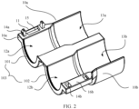
- FIG. 2 is a schematic diagram of an open state of the cable protective housing.
- a body of the cable protective housing 10 shown in FIG. 1 and FIG. 2 includes two housings.
- the two housings are respectively named a first housing 10a and a second housing 10b.
- the first housing 10a and the second housing 10b can enclose cavities that accommodate a cable connector 50 and a cable installation head 20.
- the first housing 10a is of a semi-cylindrical structure.
- the first housing 10a has two grooves: a first groove 12a and a second groove 13a.
- the first groove 12a and the second groove 13a are arranged along a length direction of the first housing 10a and communicate with each other.
- FIG. 5 is a reference diagram of a use state of the cable protective housing 10
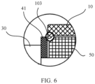
- FIG. 6 is a partial enlarged view of a position A in FIG. 5 .
- the first groove 12a is configured to accommodate the cable connector 50
- the second groove 13a is configured to accommodate the cable installation head 20.
- FIG. 3 is a schematic structural diagram of the other side of the cable protective housing. It can be learned from a structure shown in FIG. 3 that the first housing 10a includes a first housing structure 18a and a second housing structure 17a, and the first housing structure 18a is fastened and connected to the second housing structure 17a. Certainly, an integrated structure may alternatively be used, for example, the first housing structure 18a and the second housing structure 17a are integrally formed through plastic injection or by using an extrusion molding process. Still referring to FIG.
- both the first housing structure 18a and the second housing structure 17a are semi-cylindrical housing structures, and a cross-sectional size of the second housing structure 17a is greater than a cross-sectional size of the first housing structure 18a.
- an outside diameter of the second housing structure 17a is greater than an outside diameter of the first housing structure 18a.
- a step structure (not shown in the figure) is formed at a joint of the first housing structure 18a and the second housing structure 17a.
- the first groove 12a is disposed inside the first housing structure 18a, in other words, the first groove 12a is an inner cavity of the first housing structure 18a.
- the second groove 13a is disposed inside the second housing structure 17a, in other words, the second groove 13a is an inner cavity of the second housing structure 17a.
- both the first groove 12a and the second groove 13a are also semi-cylindrical grooves, and a diameter of the first groove 12a is less than a diameter of the second groove 13a.
- the diameter of the first groove 12a is greater than a diameter of the cable connector 50.
- the second groove 13 accommodates the cable installation head 20
- the diameter of the second groove 13 is also greater than a diameter of the cable installation head 20.
- first housing structure 18a and the second housing structure 17a that are of the first housing 10a use semi-cylindrical structures is merely a specific example.
- the first housing structure 18a and the second housing structure 17a provided in this embodiment of this application may alternatively use structures in a cuboid shape or another shape. It only needs to be ensured that the first groove 12a and the second groove 13a can be disposed inside the first housing structure 18a and the second housing structure 17a.
- first groove 12a and the second groove 13a shown in FIG. 2 and FIG. 3 are merely specific examples.
- the first groove 12a and the second groove 13a provided in this embodiment of this application may alternatively be grooves of other shapes such as a rectangle and a triangle.
- a minimum cross-sectional size of the first groove 12a needs to be greater than a radius of the cable connector 50
- a minimum cross-sectional size of the second groove 13a needs to be greater than a radius of the cable installation head 20. In this way, when the cable connector 50 and the cable installation head 20 are accommodated, the cable protective housing 10 is capable of rotating relative to the cable connector 50.
- the second housing 10b is symmetrical to the first housing 10a, and the second housing 10b is also of a semi-cylindrical structure.
- the second housing 10b includes a first housing structure 18b and a second housing structure 17b.
- the first housing structure 18b and the second housing structure 17b are the same as the first housing structure 18a and the second housing structure 17a that are of the first housing 10a.
- the second housing 10b also has a first groove 12b and a second groove 13b that are arranged along a length direction of the second housing 10b.
- the first groove 12b also communicates with the second groove 13b.
- first groove 12b and the second groove 13b that are of the second housing 10b refer to the foregoing specific descriptions of the first groove 12a and the second groove 13a that are of the first housing 10a.
- the first housing 10a and the second housing 10b are detachably fastened and connected.
- the first groove 12a and the first groove 12b enclose a first accommodation cavity that accommodates the cable connector 50
- the second groove 13a and the second groove 13b enclose a second accommodation cavity that accommodates the cable installation head 20.
- one side of the first housing 10a is rotatably connected to one side of the second housing 10b, and the other side of the first housing 10a may be detachably fastened and connected to the other side of the second housing 10b through fitting between a buckle 14a and a clamping slot 14b.
- the first housing 10a and the second housing 10b may be prepared in an integrally formed manner, and the side of the first housing 10a and the side of the second housing 10b that are adjacent to each other are flexibly connected, to be specific, the first housing 10a is connected to the second housing 10b by using a bendable connection part 60.
- the first housing 10a is connected to the second housing 10b, the first housing 10a is connected to the second housing 10b through deformation of the connection part 60, and the other side of the first housing 10a and the other side of the second housing 10b are connected through fitting between the buckle 14a and the clamping slot 14b.
- FIG. 2 and FIG. 3 show a specific connection manner of the first housing 10a and the second housing 10b.
- surrounding edge structures are respectively disposed on two sides of the first housing structure 18a.
- a first surrounding edge structure 19a and a second surrounding edge structure 16a are respectively disposed on the two sides of the first housing structure 18a
- first surrounding edge structure 19b and a second surrounding edge structure 16b are respectively disposed on two sides of the first housing structure 18b.
- a width of the first surrounding edge structure 19a is equal to a diameter difference between the first housing structure 18a and the second housing structure 17a.
- the first surrounding edge structure 19a is flush with the second housing structure 17a
- one side of the connection part 60 is connected to the second housing structure 17a and the first surrounding edge structure 19a
- the other side of the connection part 60 is connected to the second housing structure 17b and the first surrounding edge structure 19b.
- a width of the second surrounding edge structure 16a is greater than the diameter difference between the first housing structure 18a and the second housing structure 17a. Therefore, the second surrounding edge structure 16a protrudes outside the second housing structure 17a. Similarly, the second surrounding edge structure 16b also protrudes outside the second housing structure 17b.
- the buckle 14a when the buckle 14a and the clamping slot 14b are disposed, the buckle 14a may be disposed on an inner side of the second surrounding edge structure 16a, and the clamping slot 14b is disposed on the second surrounding edge structure 16b.
- clamping hooks of the two buckles 14a are opposite to each other, to be specific, bending directions of the clamping hooks of the two buckles 14a are opposite.
- the clamping slot 14b When the clamping slot 14b is correspondingly disposed, there may also be two clamping slots 14b, and the two clamping slots 14b are arranged along a length direction of the second surrounding edge structure 16b.
- the buckles 14a When the buckles 14a are connected to the clamping slots 14b, because the bending directions of the clamping hooks of the two buckles 14a are opposite, when a misplacement occurs between the first housing 10a and the second housing 10b in the length directions of the first housing 10a and the second housing 10b, a reliable connection can still be maintained, thereby improving reliability of the cable protective housing 10.
- the bending directions of the clamping hooks of the two buckles 14a may also be the same.
- a quantity of buckles 14a may also be set to three or more than three, and correspondingly, a quantity of clamping slots 14b may also be three or more than three.
- a notch 15 is further disposed on the second surrounding edge structure 16a of the first housing 10a.
- the notch 15 is not disposed on the second surrounding edge structure 16b of the first housing 10a.
- a flat-head screwdriver or another tool is inserted into the groove for rotation, to separate the first housing 10a and the second housing 10b.
- the two buckles 14a may be symmetrically disposed relative to the notch 15.
- the tool is used to level the buckles and the clamping slots open, it is ensured that force of the two buckles 14a is balanced.
- a baffle plate 11 that shields the notch 15 may be further disposed on the disposed second surrounding edge structure 16a.
- the baffle plate 11 is capable of rotating relative to the surrounding edge structure.
- the baffle plate 11 is integrated with the second surrounding edge structure 16a, and the baffle plate 11 is flexibly connected to the second surrounding edge structure 16a, so that the baffle plate 11 is capable of rotating relative to the notch 15. Still referring to FIG. 2 , when the baffle plate 11 is disposed, the baffle plate 11 is located inside the notch 15, and has a specified distance from a side surface of the second surrounding edge structure 16a. As shown in FIG. 1 , the baffle plate 11 is located inside the notch 15, and has the specific distance from the side surface of the second surrounding edge structure 16a. When the first housing 10a is connected to the second housing 10b, the baffle plate 11 is located inside the notch. When the tool is required to insert, the tool can be directly inserted into the exposed groove, so that the tool can be easily inserted into the notch 15, thereby facilitating a user operation.
- FIG. 2 shows only an example of a specific implementation for facilitating opening of the cable protective housing 10.
- notches may alternatively be disposed on both the second surrounding edge structure 16a and the second surrounding edge structure 16b.
- the two notches form grooves that fit the tool.
- FIG. 4 shows a use state of the cable protective housing 10.
- openings are opened at two ends of the cable protective housing 10.
- the first groove 12a and the first groove 12b enclose the first accommodation cavity that accommodates the cable connector 50, and a cross-sectional area of the first accommodation cavity is greater than a cross-sectional area of the cable connector 50.
- the second groove 13a and the second groove 13b enclose the second accommodation cavity that accommodates the cable installation head 20, and a cross-sectional area of the second accommodation cavity is greater than a cross-sectional area of the cable installation head 20.
- the first accommodation cavity and the second accommodation cavity pass through the entire cable protective housing 10.
- the cable connector 50 of a cable 30 is located inside the first accommodation cavity
- the cable installation head 20 is located inside the second accommodation cavity
- the cable protective housing 10 is capable of rotating relative to the cable connector 50 and the cable installation head 20. It can be learned from the foregoing descriptions that when the cable 30 is removed, the cable connector 50 needs to be rotated relative to the cable installation head 20.
- the cable protective housing 10 When the cable protective housing 10 provided in this embodiment of this application is sleeved on the cable connector 50 and the cable installation head 20, the cable protective housing 10 rotates relative to the cable connector 50 and the cable installation head 20 at the same time, so as to prevent the cable connector 50 from rotating relative to the cable installation head 20, thereby protecting a connection between the cable connector 50 and the cable installation head 20.
- FIG. 5 is a schematic diagram of cooperation between a connecting wire 40, the cable 30, and the cable protective housing 10.
- one end that is of the first groove 12a and that is away from the second groove 13a is provided with a limiting bulge 101 configured to be clamped into the cable 30.
- a protrusion structure is disposed at an end of the first housing structure 18a, to limit axial sliding of the cable protective housing 10.
- a limiting bulge 102 is also disposed at an end of the second housing structure 18b.
- a limiting structure 103 shown in FIG. 1 is formed on the first housing 10a and the second housing 10b.
- connection manner between the cable protective housing 10 and the cable 30, a structure of the cable 30, and a connection manner between the cable 30 and the splitting and splicing closure or the fiber access terminal are first described.
- the splitting and splicing closure is used as an example.
- the cable 30 is connected to the splitting and splicing closure through a connecting wire 40.
- Each end of the connecting wire 40 is provided with a sleeve ring.
- One sleeve ring 41 is sleeved between the cable 30 and the cable connector 50, and the other sleeve ring 41 is configured to be sleeved on the splitting and splicing closure.
- FIG. 5 is a schematic diagram of the cooperation between the connecting wire 40, the cable 30, and the cable protective housing 10
- FIG. 6 is a partial enlarged view of the position A in FIG. 5 .
- a step structure is formed between the rotating connector at an end of the cable 30 and the cable 30, the cross-sectional diameter of the cable connector 50 is greater than a cross-sectional diameter of the cable 30, and the sleeve ring 41 of the connecting wire 40 is sleeved between the cable 30 and the cable connector 50.
- the limiting is performed by using the cable 30 and the cable connector 50. In this way, axial sliding of the sleeve ring 41 is limited.
- two sides of the limiting structure 103 disposed at the end of the protective housing 10 can respectively be pressed against the sleeve ring 41 and the cable connector 50, to limit the axial sliding of the cable protective housing 10.
- the cable protective housing 10 is sleeved on the cable 30, although the diameter sizes of the first accommodation cavity and the second accommodation cavity are greater than the diameter sizes of the cable connector 50 and the cable installation head 20, the cable protective housing 10 cannot be removed from the cable connector 50 due to the axial sliding of the sleeve ring 41.
- the cable protective housing 10 cable is only capable of rotating relative to the cable connector 50 and the cable installation head 20, thereby protecting the connection between the cable connector 50 and the cable installation head 20, and preventing the cable 30 from being maliciously damaged.
- the cable 30 and the cable protective housing 10 are protected in a one-to-one correspondence.
- each cable 30 needs to be separately disassembled, only a cable protective housing 10 corresponding to the cable 30 needs to be disassembled, and another cable 30 is not affected, thereby facilitating maintenance of the cable 30.
- the limiting bulge 101 of the cable protective housing 10 is inserted into a gap between the cable 30 and the cable connector 50, to limit the axial sliding of the cable protective housing 10.
- FIG. 1 and FIG. 2 show only a specific detachable connection manner.
- the first housing 10a may be connected to the second housing 10b through the fitting between the buckles 14a and the clamping slots 14b on both sides of the first housing 10a and the second housing 10b.
- the first surrounding edge structure 19a is connected to the first surrounding edge structure 19b by using the foregoing structure of the buckle 14a and the clamping slot 14b
- the second surrounding edge structure 16a is connected to the second surrounding edge structure 16b by using the foregoing structure of the buckle 14a and the clamping slot 14b.
- the single-part and integrated cable protective housing 10 is used to implement independent protection for a single cable connector 50.
- An essence of the cable protective housing 10 is to provide independent physical protection for a single input/output cable connector.
- An application scenario does not depend on a size of the splitting and splicing closure, an arrangement of the connectors, and the like. Therefore, universality of the cable protective housing 10 is relatively strong.
- a single part design is used to ensure a simple structure and easy installation.
- An embodiment of this application further provides a communication device.
- the communication device includes a device body and at least one cable 30.
- At least one cable installation head 20 that is in a one-to-one correspondence with the at least one cable 30 is disposed on the device body.
- Each cable 30 is provided with a cable connector 50, and each cable connector 50 is detachably fastened and connected to a corresponding cable installation head 20.
- the foregoing cable protective housing 10 that is sleeved on each cable connector 50 and the corresponding cable installation head 20 is further included.
- the foregoing device body may be a splitting and splicing closure, a fiber access terminal, or another communication device.
- each cable 30 is sleeved with a connecting wire 40, and the connecting wire 40 is fastened and connected to the device body.
- an axial sliding direction of the cable protective housing 10 is limited by using a limiting bulge 101, and when the cable protective housing 10 is sleeved on the cable connector 50 and the cable installation head 20, the cable protective housing 10 is capable of rotating relative to the cable connector 50.
- the cable connector 50 needs to be rotated relative to the cable installation head 20, and the disposed cable protective housing 10 prevents the cable connector 50 from being directly rotated.
Landscapes
- Physics & Mathematics (AREA)
- General Physics & Mathematics (AREA)
- Optics & Photonics (AREA)
- Engineering & Computer Science (AREA)
- Computer Security & Cryptography (AREA)
- Details Of Connecting Devices For Male And Female Coupling (AREA)
Claims (9)
- Kabelschutzgehäuse (10), umfassend zwei Gehäuse (10a, 10b), wobei die zwei Gehäuse (10a, 10b) lösbar befestigt und verbunden sind; jedes Gehäuse (10a, 10b) eine erste Nut (12a, 12b) und eine zweite, mit der ersten Nut (12a, 12b) in Verbindung stehende Nut (13a, 13b) umfasst, und wobei ein Ende, das zu der ersten Nut (12a, 12b) gehört und von der zweiten Nut (13a, 13b) entfernt ist, mit einer Begrenzungswölbung (101, 102) bereitgestellt ist, die dazu konfiguriert ist, in ein Kabel (30) geklemmt zu werden; undwenn die zwei Gehäuse (10a, 10b) befestigt und verbunden sind, die zwei ersten Nuten (12a, 12b) einen ersten Aufnahmehohlraum umschließen, der dazu konfiguriert ist, einen Kabelverbinder (50) aufzunehmen, wobei die Begrenzungswölbung (101, 102) dazu konfiguriert ist, das axiale Gleiten des Kabelverbinders (50) und des ersten Aufnahmehohlraums zu begrenzen, und die zwei zweiten Nuten (13a, 13b) einen zweiten Aufnahmehohlraum umschließen, der einen Kabeleinbaukopf (20) aufnimmt,wobei die zwei Gehäuse (10a, 10b) durch Einpassen zwischen Schnallen (14a) und Klemmschlitzen (14b) lösbar befestigt und verbunden sind,wobei jedes Gehäuse (10a, 10b) eine erste Gehäusestruktur (18a, 18b) und eine zweite Gehäusestruktur umfasst, die mit den ersten Gehäusestrukturen (18a, 18b) verbunden ist, wobei die erste Nut (12a, 12b) innerhalb der ersten Gehäusestruktur (18a, 18b) angeordnet ist und die zweite Nut (13a, 13b) innerhalb der zweiten Gehäusestruktur (17a, 17b) angeordnet ist,wobei eine Querschnittsgröße der zweiten Gehäusestruktur größer ist als eine Querschnittsgröße der ersten Gehäusestruktur,wobei jede erste Gehäusestruktur (18a, 18b) mit einer umgebenden Kantenstruktur (16a, 16b, 19a, 19b) bereitgestellt ist, wodurch eine erste umgebende Kantenstruktur (19a) und eine zweite umgebende Kantenstruktur (16a) auf zwei Seiten der ersten Gehäusestruktur (18a) angeordnet sind und eine andere erste umgebende Kantenstruktur (19b) und eine andere zweite umgebende Kantenstruktur (16b) an zwei Seiten der anderen ersten Gehäusestruktur (18b) angeordnet sind; und wenn die zwei Gehäuse (10a, 10b) unter Verwendung der Schnallen (14a) und der Klemmschlitze (14b) lösbar befestigt und verbunden sind, die Schnallen (14a) und die Klemmschlitze (14b) jeweils und entsprechend an den umgebenden Kantenstrukturen (16a, 16b, 19a, 19b) der zwei ersten Gehäusestrukturen (18a, 18b) angeordnet sind.
- Kabelschutzgehäuse gemäß Anspruch 1, wobei
zwei Schnallen (14a) vorhanden sind und die zwei Schnallen (14a) symmetrisch angeordnet sind. - Kabelschutzgehäuse gemäß Anspruch 2,
wobei Biegerichtungen von Klemmhaken der zwei Schnallen (14a) entgegengesetzt oder gleich sind. - Kabelschutzgehäuse gemäß einem der Ansprüche 1 bis 3,
wobei eine Kerbe (15) in der umgebenden Kantenstruktur angeordnet ist. - Kabelschutzgehäuse gemäß Anspruch 4,
wobei sich die Kerbe (15) zwischen den zwei Schnallen (14a) befindet. - Kabelschutzgehäuse gemäß Anspruch 3 oder 4,
wobei eine die Kerbe (15) abschirmende Prallplatte (11) an der umgebenden Kantenstruktur angeordnet ist und die Prallplatte (11) in der Lage ist, sich in Bezug auf die umgebende Kantenstruktur zu drehen. - Kabelschutzgehäuse gemäß Anspruch 6,
wobei die Prallplatte (11) sich innerhalb der Kerbe (15) befindet und einen definierten Abstand von einer Seitenoberfläche der umgebenden Kantenstruktur aufweist. - Kommunikationsgerät, umfassend einen Gerätkörper und mindestens ein Kabel (30),wobei mindestens ein Kabeleinbaukopf (20), der in einer Einszu-Eins-Korrespondenz mit dem mindestens einen Kabel (30) steht, auf dem Gerätkörper angeordnet ist; und jedes Kabel (30) mit einem Kabelverbinder (50) bereitgestellt ist und jeder Kabelverbinder (50) mit einem entsprechenden Kabeleinbaukopf (20) lösbar befestigt und verbunden ist; undeine Schutzhülse, die auf jeden Kabelverbinder (50) und den entsprechenden Kabeleinbaukopf (20) ummantelt ist, wobei die Schutzhülse das Kabelschutzgehäuse (10) gemäß einem der Ansprüche 1 bis 7 ist.
- Kommunikationsgerät gemäß Anspruch 8,
wobei jedes Kabel (30) mit einem Verbindungsdraht (40) ummantelt ist und der Verbindungsdraht (40) an dem Gerätkörper befestigt und mit diesem verbunden ist.
Applications Claiming Priority (2)
| Application Number | Priority Date | Filing Date | Title |
|---|---|---|---|
| CN201910753594.6A CN112394454A (zh) | 2019-08-15 | 2019-08-15 | 一种线缆保护壳及通信设备 |
| PCT/CN2020/108741 WO2021027856A1 (zh) | 2019-08-15 | 2020-08-12 | 一种线缆保护壳及通信设备 |
Publications (3)
| Publication Number | Publication Date |
|---|---|
| EP3988978A1 EP3988978A1 (de) | 2022-04-27 |
| EP3988978A4 EP3988978A4 (de) | 2022-09-28 |
| EP3988978B1 true EP3988978B1 (de) | 2025-01-22 |
Family
ID=74570532
Family Applications (1)
| Application Number | Title | Priority Date | Filing Date |
|---|---|---|---|
| EP20852541.0A Active EP3988978B1 (de) | 2019-08-15 | 2020-08-12 | Kabelschutzhülle und kommunikationsgerät |
Country Status (4)
| Country | Link |
|---|---|
| EP (1) | EP3988978B1 (de) |
| CN (1) | CN112394454A (de) |
| ES (1) | ES3015242T3 (de) |
| WO (1) | WO2021027856A1 (de) |
Families Citing this family (5)
| Publication number | Priority date | Publication date | Assignee | Title |
|---|---|---|---|---|
| CN113612169B (zh) * | 2021-07-08 | 2022-11-18 | 如皋市凯凯电信器材有限公司 | 一种低互调线缆夹具 |
| CN114024276B (zh) * | 2021-11-09 | 2023-02-28 | 国网河北省电力有限公司检修分公司 | 一种电力建设电缆安装装置 |
| CN113985549A (zh) * | 2021-11-15 | 2022-01-28 | 广西电网有限责任公司崇左供电局 | 一种adss光缆引下防水防冻密封保护套及其使用方法 |
| CN114221279B (zh) * | 2021-12-16 | 2024-03-22 | 深圳供电局有限公司 | 电缆t型终端保护装置 |
| CN121394026B (zh) * | 2025-12-24 | 2026-03-31 | 中天射频电缆有限公司 | 一种分支器及复合缆结构 |
Family Cites Families (16)
| Publication number | Priority date | Publication date | Assignee | Title |
|---|---|---|---|---|
| US7432445B2 (en) * | 2006-12-18 | 2008-10-07 | Ford Global Technologies, Llc | Wire inline T tap/splice |
| CN201594579U (zh) * | 2010-01-15 | 2010-09-29 | 北京阳光天成科技发展有限公司 | 天馈线接头保护盒 |
| CN201789149U (zh) * | 2010-08-10 | 2011-04-06 | 泰科电子(上海)有限公司 | 用于密封连接件的密封装置 |
| CN201994622U (zh) * | 2010-09-20 | 2011-09-28 | 林香山 | 一种线缆接头双层保护盒 |
| CN103163597B (zh) * | 2011-12-15 | 2015-09-09 | 罗森伯格亚太电子有限公司 | 光缆连接器 |
| CN203103895U (zh) * | 2013-03-11 | 2013-07-31 | 泰科电子(上海)有限公司 | 接头保护盒和接头组件 |
| US9616602B2 (en) * | 2013-07-10 | 2017-04-11 | Commscope Technologies Llc | Interconnection seal |
| US9395509B2 (en) * | 2014-06-23 | 2016-07-19 | Commscope Technologies Llc | Fiber cable fan-out assembly and method |
| WO2016143202A1 (ja) * | 2015-03-06 | 2016-09-15 | 株式会社フジクラ | プラグ側光コネクタ及び光コネクタシステム |
| DE102015113086B4 (de) * | 2015-08-07 | 2020-04-09 | Norma Germany Gmbh | Steckverbindungsvorrichtung mit Leitungssteckverbinder und Windschutzhülle |
| US10591677B2 (en) * | 2016-03-09 | 2020-03-17 | Preformed Line Products, Co. | Retrofit cover for fiber optic cable connection |
| CN206024338U (zh) * | 2016-09-23 | 2017-03-15 | 嘉兴依相动力科技有限公司 | 一种新型ecu外壳 |
| WO2019040824A1 (en) * | 2017-08-24 | 2019-02-28 | Commscope Technologies Llc | FIBER OPTIC CONNECTION ASSEMBLIES, CHARACTERISTICS, COMPONENTS AND METHODS |
| CN207623575U (zh) * | 2017-10-27 | 2018-07-17 | 杭州七友通信科技有限公司 | 一种新型光纤保护盒 |
| CN108063313B (zh) * | 2017-12-12 | 2018-10-30 | 长春巨龙通信设备股份有限公司 | 一种便于安装的防渗天馈线系统 |
| CN208991300U (zh) * | 2018-09-07 | 2019-06-18 | 深圳市宇轩网络技术有限公司 | 一种光纤连接器清洁器卡接结构及清洁器 |
-
2019
- 2019-08-15 CN CN201910753594.6A patent/CN112394454A/zh active Pending
-
2020
- 2020-08-12 EP EP20852541.0A patent/EP3988978B1/de active Active
- 2020-08-12 WO PCT/CN2020/108741 patent/WO2021027856A1/zh not_active Ceased
- 2020-08-12 ES ES20852541T patent/ES3015242T3/es active Active
Also Published As
| Publication number | Publication date |
|---|---|
| EP3988978A1 (de) | 2022-04-27 |
| WO2021027856A1 (zh) | 2021-02-18 |
| ES3015242T3 (en) | 2025-04-30 |
| CN112394454A (zh) | 2021-02-23 |
| EP3988978A4 (de) | 2022-09-28 |
Similar Documents
| Publication | Publication Date | Title |
|---|---|---|
| EP3988978A1 (de) | Kabelschutzhülle und kommunikationsgerät | |
| US6793524B2 (en) | Multimedia outlet with protective cover | |
| EP3671299B1 (de) | Verbinderanordnung sowie steckverbinder und kerneinheit dafür | |
| US6491546B1 (en) | Locking F terminator for coaxial cable systems | |
| US5166995A (en) | Polarized connector | |
| EP1172672B1 (de) | Staubabdeckung für faseroptischen Steckverbinder mit zwei Funktionen | |
| EP4191301B1 (de) | Glasfaserstecker, glasfaseradapter, steckeranordnung und kommunikationsvorrichtung | |
| US6540547B2 (en) | Cable harness plug having a securing device for the cable harness | |
| EP4191297B1 (de) | Glasfaserstecker, glasfaseradapter, steckeranordnung und kommunikationsvorrichtung | |
| EP3693773B1 (de) | Faseroptischer verbinder und faseroptische verbindungsanordnung | |
| US20100190364A1 (en) | Plug assembly, attachment plug and conversion plug | |
| JPH01316711A (ja) | 光コネクタ組立体 | |
| EP1186921B1 (de) | Stecker oder Adapter für optisches Kabel | |
| US9967440B2 (en) | Housing and a camera comprising a housing | |
| EP3700035B1 (de) | Modularer verteilerkasten für kabel | |
| US8606061B2 (en) | Cable assembly having quick-locking connector and premise wiring systems utilizing same | |
| US20240128697A1 (en) | Plug assembly | |
| EP2715876B1 (de) | Gehäuse für einen elektrischen verbinder und vorrichtung für ein fahrzeugaufladesystem | |
| CN104714279B (zh) | 一种光纤连接器的固定装置 | |
| WO2018119147A1 (en) | Fiber tap optical cross connect terminal closure and terminal splice closure | |
| IT201900011643A1 (it) | Dispositivo di presa per rete in fibra ottica. | |
| EP1755198B1 (de) | Hochfrequenz Wandsteckdose und Verbindungsmodul | |
| EP1202395B1 (de) | Versiegelungsvorrichtung | |
| JPH09274122A (ja) | 光ケーブルクロージャ | |
| CN113325520A (zh) | 光连接设备及局域网路系统 |
Legal Events
| Date | Code | Title | Description |
|---|---|---|---|
| STAA | Information on the status of an ep patent application or granted ep patent |
Free format text: STATUS: THE INTERNATIONAL PUBLICATION HAS BEEN MADE |
|
| PUAI | Public reference made under article 153(3) epc to a published international application that has entered the european phase |
Free format text: ORIGINAL CODE: 0009012 |
|
| STAA | Information on the status of an ep patent application or granted ep patent |
Free format text: STATUS: REQUEST FOR EXAMINATION WAS MADE |
|
| 17P | Request for examination filed |
Effective date: 20220120 |
|
| AK | Designated contracting states |
Kind code of ref document: A1 Designated state(s): AL AT BE BG CH CY CZ DE DK EE ES FI FR GB GR HR HU IE IS IT LI LT LU LV MC MK MT NL NO PL PT RO RS SE SI SK SM TR |
|
| A4 | Supplementary search report drawn up and despatched |
Effective date: 20220826 |
|
| RIC1 | Information provided on ipc code assigned before grant |
Ipc: G02B 6/44 20060101AFI20220823BHEP |
|
| DAV | Request for validation of the european patent (deleted) | ||
| DAX | Request for extension of the european patent (deleted) | ||
| GRAP | Despatch of communication of intention to grant a patent |
Free format text: ORIGINAL CODE: EPIDOSNIGR1 |
|
| STAA | Information on the status of an ep patent application or granted ep patent |
Free format text: STATUS: GRANT OF PATENT IS INTENDED |
|
| RIC1 | Information provided on ipc code assigned before grant |
Ipc: G02B 6/38 20060101ALI20240819BHEP Ipc: G02B 6/44 20060101AFI20240819BHEP |
|
| INTG | Intention to grant announced |
Effective date: 20240910 |
|
| GRAS | Grant fee paid |
Free format text: ORIGINAL CODE: EPIDOSNIGR3 |
|
| GRAA | (expected) grant |
Free format text: ORIGINAL CODE: 0009210 |
|
| STAA | Information on the status of an ep patent application or granted ep patent |
Free format text: STATUS: THE PATENT HAS BEEN GRANTED |
|
| AK | Designated contracting states |
Kind code of ref document: B1 Designated state(s): AL AT BE BG CH CY CZ DE DK EE ES FI FR GB GR HR HU IE IS IT LI LT LU LV MC MK MT NL NO PL PT RO RS SE SI SK SM TR |
|
| REG | Reference to a national code |
Ref country code: GB Ref legal event code: FG4D |
|
| REG | Reference to a national code |
Ref country code: CH Ref legal event code: EP |
|
| REG | Reference to a national code |
Ref country code: IE Ref legal event code: FG4D |
|
| REG | Reference to a national code |
Ref country code: DE Ref legal event code: R096 Ref document number: 602020045287 Country of ref document: DE |
|
| REG | Reference to a national code |
Ref country code: ES Ref legal event code: FG2A Ref document number: 3015242 Country of ref document: ES Kind code of ref document: T3 Effective date: 20250430 |
|
| REG | Reference to a national code |
Ref country code: NL Ref legal event code: MP Effective date: 20250122 |
|
| PG25 | Lapsed in a contracting state [announced via postgrant information from national office to epo] |
Ref country code: NL Free format text: LAPSE BECAUSE OF FAILURE TO SUBMIT A TRANSLATION OF THE DESCRIPTION OR TO PAY THE FEE WITHIN THE PRESCRIBED TIME-LIMIT Effective date: 20250122 |
|
| PG25 | Lapsed in a contracting state [announced via postgrant information from national office to epo] |
Ref country code: RS Free format text: LAPSE BECAUSE OF FAILURE TO SUBMIT A TRANSLATION OF THE DESCRIPTION OR TO PAY THE FEE WITHIN THE PRESCRIBED TIME-LIMIT Effective date: 20250422 |
|
| PG25 | Lapsed in a contracting state [announced via postgrant information from national office to epo] |
Ref country code: FI Free format text: LAPSE BECAUSE OF FAILURE TO SUBMIT A TRANSLATION OF THE DESCRIPTION OR TO PAY THE FEE WITHIN THE PRESCRIBED TIME-LIMIT Effective date: 20250122 |
|
| PG25 | Lapsed in a contracting state [announced via postgrant information from national office to epo] |
Ref country code: PL Free format text: LAPSE BECAUSE OF FAILURE TO SUBMIT A TRANSLATION OF THE DESCRIPTION OR TO PAY THE FEE WITHIN THE PRESCRIBED TIME-LIMIT Effective date: 20250122 |
|
| REG | Reference to a national code |
Ref country code: LT Ref legal event code: MG9D |
|
| PG25 | Lapsed in a contracting state [announced via postgrant information from national office to epo] |
Ref country code: NO Free format text: LAPSE BECAUSE OF FAILURE TO SUBMIT A TRANSLATION OF THE DESCRIPTION OR TO PAY THE FEE WITHIN THE PRESCRIBED TIME-LIMIT Effective date: 20250422 Ref country code: IS Free format text: LAPSE BECAUSE OF FAILURE TO SUBMIT A TRANSLATION OF THE DESCRIPTION OR TO PAY THE FEE WITHIN THE PRESCRIBED TIME-LIMIT Effective date: 20250522 |
|
| REG | Reference to a national code |
Ref country code: AT Ref legal event code: MK05 Ref document number: 1761883 Country of ref document: AT Kind code of ref document: T Effective date: 20250122 |
|
| PG25 | Lapsed in a contracting state [announced via postgrant information from national office to epo] |
Ref country code: HR Free format text: LAPSE BECAUSE OF FAILURE TO SUBMIT A TRANSLATION OF THE DESCRIPTION OR TO PAY THE FEE WITHIN THE PRESCRIBED TIME-LIMIT Effective date: 20250122 |
|
| PG25 | Lapsed in a contracting state [announced via postgrant information from national office to epo] |
Ref country code: LV Free format text: LAPSE BECAUSE OF FAILURE TO SUBMIT A TRANSLATION OF THE DESCRIPTION OR TO PAY THE FEE WITHIN THE PRESCRIBED TIME-LIMIT Effective date: 20250122 Ref country code: PT Free format text: LAPSE BECAUSE OF FAILURE TO SUBMIT A TRANSLATION OF THE DESCRIPTION OR TO PAY THE FEE WITHIN THE PRESCRIBED TIME-LIMIT Effective date: 20250522 |
|
| PG25 | Lapsed in a contracting state [announced via postgrant information from national office to epo] |
Ref country code: BG Free format text: LAPSE BECAUSE OF FAILURE TO SUBMIT A TRANSLATION OF THE DESCRIPTION OR TO PAY THE FEE WITHIN THE PRESCRIBED TIME-LIMIT Effective date: 20250122 Ref country code: GR Free format text: LAPSE BECAUSE OF FAILURE TO SUBMIT A TRANSLATION OF THE DESCRIPTION OR TO PAY THE FEE WITHIN THE PRESCRIBED TIME-LIMIT Effective date: 20250423 |
|
| PG25 | Lapsed in a contracting state [announced via postgrant information from national office to epo] |
Ref country code: AT Free format text: LAPSE BECAUSE OF FAILURE TO SUBMIT A TRANSLATION OF THE DESCRIPTION OR TO PAY THE FEE WITHIN THE PRESCRIBED TIME-LIMIT Effective date: 20250122 |
|
| PG25 | Lapsed in a contracting state [announced via postgrant information from national office to epo] |
Ref country code: SE Free format text: LAPSE BECAUSE OF FAILURE TO SUBMIT A TRANSLATION OF THE DESCRIPTION OR TO PAY THE FEE WITHIN THE PRESCRIBED TIME-LIMIT Effective date: 20250122 |
|
| PG25 | Lapsed in a contracting state [announced via postgrant information from national office to epo] |
Ref country code: SM Free format text: LAPSE BECAUSE OF FAILURE TO SUBMIT A TRANSLATION OF THE DESCRIPTION OR TO PAY THE FEE WITHIN THE PRESCRIBED TIME-LIMIT Effective date: 20250122 |
|
| PGFP | Annual fee paid to national office [announced via postgrant information from national office to epo] |
Ref country code: ES Payment date: 20250905 Year of fee payment: 6 |
|
| PG25 | Lapsed in a contracting state [announced via postgrant information from national office to epo] |
Ref country code: DK Free format text: LAPSE BECAUSE OF FAILURE TO SUBMIT A TRANSLATION OF THE DESCRIPTION OR TO PAY THE FEE WITHIN THE PRESCRIBED TIME-LIMIT Effective date: 20250122 |
|
| PG25 | Lapsed in a contracting state [announced via postgrant information from national office to epo] |
Ref country code: IT Free format text: LAPSE BECAUSE OF FAILURE TO SUBMIT A TRANSLATION OF THE DESCRIPTION OR TO PAY THE FEE WITHIN THE PRESCRIBED TIME-LIMIT Effective date: 20250122 |
|
| PG25 | Lapsed in a contracting state [announced via postgrant information from national office to epo] |
Ref country code: CZ Free format text: LAPSE BECAUSE OF FAILURE TO SUBMIT A TRANSLATION OF THE DESCRIPTION OR TO PAY THE FEE WITHIN THE PRESCRIBED TIME-LIMIT Effective date: 20250122 Ref country code: EE Free format text: LAPSE BECAUSE OF FAILURE TO SUBMIT A TRANSLATION OF THE DESCRIPTION OR TO PAY THE FEE WITHIN THE PRESCRIBED TIME-LIMIT Effective date: 20250122 |
|
| REG | Reference to a national code |
Ref country code: DE Ref legal event code: R097 Ref document number: 602020045287 Country of ref document: DE |
|
| PG25 | Lapsed in a contracting state [announced via postgrant information from national office to epo] |
Ref country code: RO Free format text: LAPSE BECAUSE OF FAILURE TO SUBMIT A TRANSLATION OF THE DESCRIPTION OR TO PAY THE FEE WITHIN THE PRESCRIBED TIME-LIMIT Effective date: 20250122 |
|
| PG25 | Lapsed in a contracting state [announced via postgrant information from national office to epo] |
Ref country code: SK Free format text: LAPSE BECAUSE OF FAILURE TO SUBMIT A TRANSLATION OF THE DESCRIPTION OR TO PAY THE FEE WITHIN THE PRESCRIBED TIME-LIMIT Effective date: 20250122 |
|
| PLBE | No opposition filed within time limit |
Free format text: ORIGINAL CODE: 0009261 |
|
| STAA | Information on the status of an ep patent application or granted ep patent |
Free format text: STATUS: NO OPPOSITION FILED WITHIN TIME LIMIT |
|
| REG | Reference to a national code |
Ref country code: CH Ref legal event code: L10 Free format text: ST27 STATUS EVENT CODE: U-0-0-L10-L00 (AS PROVIDED BY THE NATIONAL OFFICE) Effective date: 20251203 |
|
| 26N | No opposition filed |
Effective date: 20251023 |
|
| REG | Reference to a national code |
Ref country code: DE Ref legal event code: R119 Ref document number: 602020045287 Country of ref document: DE |
|
| REG | Reference to a national code |
Ref country code: CH Ref legal event code: H13 Free format text: ST27 STATUS EVENT CODE: U-0-0-H10-H13 (AS PROVIDED BY THE NATIONAL OFFICE) Effective date: 20260324 |
|
| PG25 | Lapsed in a contracting state [announced via postgrant information from national office to epo] |
Ref country code: MC Free format text: LAPSE BECAUSE OF FAILURE TO SUBMIT A TRANSLATION OF THE DESCRIPTION OR TO PAY THE FEE WITHIN THE PRESCRIBED TIME-LIMIT Effective date: 20250122 |
|
| PG25 | Lapsed in a contracting state [announced via postgrant information from national office to epo] |
Ref country code: LU Free format text: LAPSE BECAUSE OF NON-PAYMENT OF DUE FEES Effective date: 20250812 |
|
| PG25 | Lapsed in a contracting state [announced via postgrant information from national office to epo] |
Ref country code: CH Free format text: LAPSE BECAUSE OF NON-PAYMENT OF DUE FEES Effective date: 20250831 |
|
| GBPC | Gb: european patent ceased through non-payment of renewal fee |
Effective date: 20250812 |