EP4191301B1 - Glasfaserstecker, glasfaseradapter, steckeranordnung und kommunikationsvorrichtung - Google Patents
Glasfaserstecker, glasfaseradapter, steckeranordnung und kommunikationsvorrichtung Download PDFInfo
- Publication number
- EP4191301B1 EP4191301B1 EP21859556.9A EP21859556A EP4191301B1 EP 4191301 B1 EP4191301 B1 EP 4191301B1 EP 21859556 A EP21859556 A EP 21859556A EP 4191301 B1 EP4191301 B1 EP 4191301B1
- Authority
- EP
- European Patent Office
- Prior art keywords
- front cover
- face
- fiber
- connector plug
- ferrule
- Prior art date
- Legal status (The legal status is an assumption and is not a legal conclusion. Google has not performed a legal analysis and makes no representation as to the accuracy of the status listed.)
- Active
Links
Images















Classifications
-
- G—PHYSICS
- G02—OPTICS
- G02B—OPTICAL ELEMENTS, SYSTEMS OR APPARATUS
- G02B6/00—Light guides; Structural details of arrangements comprising light guides and other optical elements, e.g. couplings
- G02B6/24—Coupling light guides
- G02B6/36—Mechanical coupling means
- G02B6/38—Mechanical coupling means having fibre to fibre mating means
- G02B6/3807—Dismountable connectors, i.e. comprising plugs
- G02B6/3869—Mounting ferrules to connector body, i.e. plugs
- G02B6/387—Connector plugs comprising two complementary members, e.g. shells, caps, covers, locked together
-
- G—PHYSICS
- G02—OPTICS
- G02B—OPTICAL ELEMENTS, SYSTEMS OR APPARATUS
- G02B6/00—Light guides; Structural details of arrangements comprising light guides and other optical elements, e.g. couplings
- G02B6/24—Coupling light guides
- G02B6/36—Mechanical coupling means
- G02B6/38—Mechanical coupling means having fibre to fibre mating means
- G02B6/3807—Dismountable connectors, i.e. comprising plugs
- G02B6/381—Dismountable connectors, i.e. comprising plugs of the ferrule type, e.g. fibre ends embedded in ferrules, connecting a pair of fibres
- G02B6/3825—Dismountable connectors, i.e. comprising plugs of the ferrule type, e.g. fibre ends embedded in ferrules, connecting a pair of fibres with an intermediate part, e.g. adapter, receptacle, linking two plugs
-
- G—PHYSICS
- G02—OPTICS
- G02B—OPTICAL ELEMENTS, SYSTEMS OR APPARATUS
- G02B6/00—Light guides; Structural details of arrangements comprising light guides and other optical elements, e.g. couplings
- G02B6/24—Coupling light guides
- G02B6/36—Mechanical coupling means
- G02B6/38—Mechanical coupling means having fibre to fibre mating means
- G02B6/3807—Dismountable connectors, i.e. comprising plugs
- G02B6/3833—Details of mounting fibres in ferrules; Assembly methods; Manufacture
- G02B6/3847—Details of mounting fibres in ferrules; Assembly methods; Manufacture with means preventing fibre end damage, e.g. recessed fibre surfaces
- G02B6/3849—Details of mounting fibres in ferrules; Assembly methods; Manufacture with means preventing fibre end damage, e.g. recessed fibre surfaces using mechanical protective elements, e.g. caps, hoods, sealing membranes
-
- G—PHYSICS
- G02—OPTICS
- G02B—OPTICAL ELEMENTS, SYSTEMS OR APPARATUS
- G02B6/00—Light guides; Structural details of arrangements comprising light guides and other optical elements, e.g. couplings
- G02B6/24—Coupling light guides
- G02B6/36—Mechanical coupling means
- G02B6/38—Mechanical coupling means having fibre to fibre mating means
- G02B6/3807—Dismountable connectors, i.e. comprising plugs
- G02B6/3869—Mounting ferrules to connector body, i.e. plugs
-
- G—PHYSICS
- G02—OPTICS
- G02B—OPTICAL ELEMENTS, SYSTEMS OR APPARATUS
- G02B6/00—Light guides; Structural details of arrangements comprising light guides and other optical elements, e.g. couplings
- G02B6/24—Coupling light guides
- G02B6/36—Mechanical coupling means
- G02B6/38—Mechanical coupling means having fibre to fibre mating means
- G02B6/3807—Dismountable connectors, i.e. comprising plugs
- G02B6/3873—Connectors using guide surfaces for aligning ferrule ends, e.g. tubes, sleeves, V-grooves, rods, pins, balls
- G02B6/3874—Connectors using guide surfaces for aligning ferrule ends, e.g. tubes, sleeves, V-grooves, rods, pins, balls using tubes, sleeves to align ferrules
-
- G—PHYSICS
- G02—OPTICS
- G02B—OPTICAL ELEMENTS, SYSTEMS OR APPARATUS
- G02B6/00—Light guides; Structural details of arrangements comprising light guides and other optical elements, e.g. couplings
- G02B6/24—Coupling light guides
- G02B6/36—Mechanical coupling means
- G02B6/38—Mechanical coupling means having fibre to fibre mating means
- G02B6/3807—Dismountable connectors, i.e. comprising plugs
- G02B6/3873—Connectors using guide surfaces for aligning ferrule ends, e.g. tubes, sleeves, V-grooves, rods, pins, balls
- G02B6/3881—Connectors using guide surfaces for aligning ferrule ends, e.g. tubes, sleeves, V-grooves, rods, pins, balls using grooves to align ferrule ends
-
- G—PHYSICS
- G02—OPTICS
- G02B—OPTICAL ELEMENTS, SYSTEMS OR APPARATUS
- G02B6/00—Light guides; Structural details of arrangements comprising light guides and other optical elements, e.g. couplings
- G02B6/24—Coupling light guides
- G02B6/36—Mechanical coupling means
- G02B6/38—Mechanical coupling means having fibre to fibre mating means
- G02B6/3807—Dismountable connectors, i.e. comprising plugs
- G02B6/389—Dismountable connectors, i.e. comprising plugs characterised by the method of fastening connecting plugs and sockets, e.g. screw- or nut-lock, snap-in, bayonet type
-
- G—PHYSICS
- G02—OPTICS
- G02B—OPTICAL ELEMENTS, SYSTEMS OR APPARATUS
- G02B6/00—Light guides; Structural details of arrangements comprising light guides and other optical elements, e.g. couplings
- G02B6/24—Coupling light guides
- G02B6/36—Mechanical coupling means
- G02B6/38—Mechanical coupling means having fibre to fibre mating means
- G02B6/3807—Dismountable connectors, i.e. comprising plugs
- G02B6/3897—Connectors fixed to housings, casing, frames or circuit boards
-
- G—PHYSICS
- G02—OPTICS
- G02B—OPTICAL ELEMENTS, SYSTEMS OR APPARATUS
- G02B6/00—Light guides; Structural details of arrangements comprising light guides and other optical elements, e.g. couplings
- G02B6/44—Mechanical structures for providing tensile strength and external protection for fibres, e.g. optical transmission cables
- G02B6/4401—Optical cables
- G02B6/4429—Means specially adapted for strengthening or protecting the cables
- G02B6/443—Protective covering
-
- G—PHYSICS
- G02—OPTICS
- G02B—OPTICAL ELEMENTS, SYSTEMS OR APPARATUS
- G02B6/00—Light guides; Structural details of arrangements comprising light guides and other optical elements, e.g. couplings
- G02B6/44—Mechanical structures for providing tensile strength and external protection for fibres, e.g. optical transmission cables
- G02B6/4439—Auxiliary devices
- G02B6/444—Systems or boxes with surplus lengths
- G02B6/4441—Boxes
Definitions
- This application relates to the field of optical communications, and in particular, to a fiber connector plug and a connector assembly.
- Document CN 110 542 952 A describes an optical fiber joint and an optical fiber connector.
- Document CN 111 308 615 A describes an optical fiber connector plug, an optical fiber adapter and an optical fiber connector.
- Embodiments of this application provide a fiber connector plug and a connector assembly according to the independent claims, to implement a miniaturization design of the fiber connector plug, so that more fiber connection ports can be arranged in a limited space.
- this application provides a fiber connector plug, including a fiber, a ferrule fastened to a front end of the fiber, a main housing sleeved over a periphery of the fiber, and a front cover.
- the main housing is sleeve-shaped.
- the front cover is fastened to one end of the main housing and encircles the ferrule.
- An end face that is of the ferrule and that is away from the fiber is a front end face of the ferrule
- an end face that is of the front cover and that is away from the main housing is a front end face of the front cover.
- the front end face of the ferrule is flush with the front end face of the front cover.
- the front end face of the ferrule is aligned with the front end face of the front cover.
- the front end face of the ferrule is located between the front end face of the front cover and a rear end face of the front cover.
- the rear end face of the front cover is an end face that is of the front cover and that faces the main housing.
- a slot is formed between the front cover and the ferrule, and the slot is used to accommodate a ferrule sleeve of a fiber adapter, so that an end face of the ferrule sleeve is located in the slot.
- a front end of the ferrule sleeve is all inserted into the slot, and a radial size of the ferrule sleeve matches a radial size of the slot, that is, the radial sizes of the ferrule sleeve and the slot may be equal, or a difference between the radial sizes of the ferrule sleeve and the slot meets machining tolerance and assembling clearance.
- the slot accommodates no other element than the ferrule.
- the ferrule is used to be inserted into the ferrule sleeve.
- a first guide structure is disposed on an outer surface of the front cover, and the first guide structure is used to fit a guide key on the fiber adapter;
- a second guide structure is disposed on an outer surface of the main housing, and the second guide structure and the first guide structure are connected and are jointly used to fit the guide key on the fiber adapter; and the second guide structure is a groove structure, a cut structures, or a protrusion structure.
- the main housing comprises a main shaft and a mounting member that are both sleeve-shaped, and the mounting member is connected to an end that is of the main shaft and that faces the front cover; a first stop structure is disposed on an outer surface of the ferrule, the mounting member comprises a mounting member body and a second stop structure, and the second stop structure is located at a front end of the mounting member body and protrudes from an inner surface of the mounting member body; and a part of the ferrule is accommodated inside the mounting member, the first stop structure fits the second stop structure to prevent the ferrule from moving out of the mounting member from the front end of the mounting member body, and the front cover is sleeved over an outer surface of the mounting member and is fastened to the mounting member; wherein a rear end of the fiber connector plug is an end of the fiber connector plug facing away from the ferrule; and wherein a rear end face of the mounting member body and the rear end face of the front cover are coplanar and jointly form a connecting face, and the connecting
- the front end face of the ferrule is protected by using the front end face of the front cover, so that the front end face of the ferrule can be prevented from being scratched.
- the front cover can protect the front end face of the ferrule in a process of turnover, transportation, and insertion into and removal from the fiber adapter.
- the slot is used to accommodate one end of the ferrule sleeve, and the end face of the ferrule sleeve extends into the slot.
- the front cover has functions of protecting the front end face of the ferrule and fitting the fiber adapter, and no other component needs to be disposed in a periphery of the front cover. Therefore, a radial size of the fiber connector plug can be small enough, so that more fiber connection ports can be arranged in a limited space of a communications device.
- an outer surface of the front cover is also an outer surface of the entire fiber connector plug, that is, there is only one front cover structural member in a periphery of the ferrule.
- a protection feature (the front end face of the front cover) configured in the periphery of the ferrule and an insertion/removal fit feature (the slot formed between an inner surface of the front cover and the ferrule, and a fit between the outer surface of the front cover and an inner surface of the fiber adapter) are concentrated on the front cover. This can not only reduce parts and simplify a structure of the fiber connector plug, but also facilitate a miniaturization design of the radial size.
- a first guide structure is disposed on the outer surface of the front cover, and the first guide structure is used to fit a guide key on the fiber adapter.
- the outer surface of the front cover provided in this application is in contact with and fits the inner surface of the fiber adapter, and the first guide structure may fit the guide key to provide guidance in a process of inserting the fiber connector plug into the fiber adapter.
- the first guide structure extends along the axial direction
- the fiber connector plug having the first guide structure extending along the axial direction can be inserted into or removed from the fiber adapter in a manner of direct insertion or direct removal, and there is no rotation action in an insertion process.
- This design helps reduce an operation space around the fiber connector plug.
- the first guide structure in the radial direction, is a groove structure disposed on the outer surface of the front cover, that is, the first guide structure does not penetrate the inner surface of the front cover.
- a notch may be disposed in a position, close to the front end face, of the front cover. Disposing of the notch enables the front end face to form a non-closed ring-shaped structure or a structure with at least two faces (for example, when there are two notches, the front end face is divided into a first face and a second face).
- the first guide structure that is the groove structure and that is disposed on the outer surface of the front cover has an opening formed on one side facing the front end face, and the opening communicates with the notch.
- the first guide structure and the notch can provide an eye-catching reminding function for alignment in a process of inserting the fiber connector plug.
- the first guide structure penetrates the inner surface and the outer surface of the front cover. It may be understood that the first guide structure is a notch or a hollowed-out structure disposed on the front cover.
- the first guide structure is protrudingly disposed on the outer surface of the front cover.
- the first guide structure may extend from the front end face of the front cover to the rear end face of the front cover, or may extend from the front end face of the front cover to a middle position of the front cover.
- the middle position herein is a position between the front end face and the rear end face.
- the middle position not only represents a central position between the front end face and the rear end face, but also may be a position close to the front end face or may be a position close to the rear end face.
- first guide structures there may be one, two, or more first guide structures.
- Two or more first guide structures may be evenly disposed on the outer surface of the front cover at intervals in a circumferential direction.
- a second guide structure is disposed on an outer surface of the main housing, and the second guide structure and the first guide structure are connected and are jointly used to fit the guide key on the fiber adapter.
- the first guide structure and the second guide structure may be the same.
- both the first guide structure and the second guide structure are groove structures, cut structures, or protrusion structures.
- the first guide structure and the second guide structure may be different.
- the first guide structure is a groove structure, and the second guide structure is a cut structure; or the first guide structure is a cut structure, and the second guide structure is a protrusion structure.
- the first guide structure is disposed (or the first guide structure is combined with the second guide structure), so that in a process in which the fiber connector plug is connected to the fiber adapter, the front cover can have an eye-catching reminding and guiding function. This facilitates alignment between the fiber connector plug and the fiber adapter, improves accuracy of connection, prevents a ferrule component of the fiber connector plug from being damaged or invalid due to a plurality of collisions caused by incorrect insertion of the fiber connector plug, and effectively prolongs a service life of the fiber connector plug.
- the front end face of the front cover is in a closed ring structure.
- one notch is disposed at an end that is of the front cover and that is close to the front end face of the front cover, so that the front end face of the front cover forms a non-closed continuously extending surface. Disposing of the notch enables the front end of the fiber connector plug to present a concave-convex shape suitable for insertion. In this way, when the fiber connector plug is inserted into the fiber adapter, the fiber connector plug can better adapt to an internal space of the fiber adapter in comparison with a front end of a fiber connector plug in a flat shape. Therefore, a loose connection caused by a limitation of the internal space of the fiber adapter is avoided, stability and reliability of insertion are improved, practicability is higher, and an application range is wide.
- the two notches are designed to resolve a problem of the interference fit in the connection.
- the positions of the two notches can accommodate a part of an area in which a front end face of another front cover is located.
- the two notches may be symmetrically disposed on the two sides of the central axis of the front cover.
- the notch disposed at the front end of the front cover is also advantageous for observation.
- a worker can see at least the front end face of the ferrule when viewing an outer surface of the outer frame sleeve disposed with the notch. Based on this, when connecting the fiber connection plug to the fiber adapter, the worker can see a position of the ferrule. This facilitates insertion, improves an insertion success rate, prevents the ferrule from suffering a plurality of collisions due to wrong insertion, and prevents the ferrule from being damaged.
- a first limiting structure is disposed on a surface of the ferrule
- a second limiting structure is disposed on the inner surface of the front cover
- the first limiting structure fits the second limiting structure to prevent the ferrule and the front cover from rotating relative to each other.
- the first limiting structure includes a first plane
- the second limiting structure is protrudingly disposed on the inner surface of the front cover
- the second limiting structure includes a second plane facing the ferrule
- the first plane is in contact with the second plane.
- Limiting structures namely, the first limiting structure and the second limiting structure, are disposed between the front cover and the ferrule that are provided in this application. It may be understood that an outer surface of the ferrule is in direct contact with and fits the inner surface of the front cover. This architecture makes a structure between the ferrule and the front cover more compact, thereby facilitating the miniaturization design.
- the main housing includes a main shaft and a mounting member that are both sleeve-shaped, and the mounting member is connected to an end that is of the main shaft and that faces the front cover; a first stop structure is disposed on the outer surface of the ferrule, the mounting member includes a mounting member body and a second stop structure, and the second stop structure is located at a front end of the mounting member body and protrudes from an inner surface of the mounting member body; and a part of the ferrule is accommodated inside the mounting member, the first stop structure fits the second stop structure to prevent the ferrule from moving out of the mounting member from the front end of the mounting member body, and the front cover is sleeved over an outer surface of the mounting member and is fastened to the mounting member.
- assembling between the ferrule and the main shaft is implemented by using the mounting member.
- a specific position of the ferrule on the main shaft is determined, and the front cover is directly sleeved over a periphery of the mounting member.
- the inside of the mounting member is used to mount the ferrule
- the outside of the mounting member is used to mount the front cover
- a rear end of the mounting member is used to connect to the main shaft.
- multi-dimensional assembling and connection relationships are implemented by using a mounting member structure, so that the structure of the fiber connector plug tends to be simplified and that the miniaturization design is easily implemented.
- the first limiting structure and the first stop structure of the ferrule are adjacent in the axial direction
- the first stop structure includes a first limiting face facing a front end of the ferrule
- the first limiting face is vertically connected to the first plane of the first limiting structure.
- the mounting member body is sleeve-shaped and includes a central axis
- the second stop structure protrudes from the inner surface of the mounting member body
- the second stop structure includes a second limiting face and a contact face.
- the second limiting face faces a rear end of the mounting member body
- the contact face faces the central axis of the mounting member body.
- the second limiting face is used to fit the first limiting face of the first stop structure of the ferrule.
- the contact face is used to fit the first plane of the first limiting structure of the ferrule.
- An axial size of one second stop structure is less than an axial size of the other second stop structure.
- One side that is of one second stop structure and that is away from the mounting member body forms a mounting member notch.
- a position of the mounting member notch directly faces a part of a contact face of the other second stop structure.
- the mounting member notch is used to accommodate the second limiting structure of the front cover.
- the mounting member further includes an elastic clamping hook.
- the elastic clamping hook is formed at the front end of the mounting member body.
- the front cover is disposed with a clamping groove or a hole.
- the elastic clamping hook fits the clamping groove or the hole, to fasten the mounting member to the front cover.
- a fastening manner based on a fit between the elastic clamping hook and the hole can implement a detachable connection between the mounting member and the front cover to facilitate assembling and disassembling.
- the elastic clamping hook is clamped into the hole, and the elastic clamping hook occupies an internal space of the front cover, without increasing a radial size of the fiber connector plug.
- the front cover is sleeved over the periphery of the mounting member in a manner of direct insertion along the axial direction, so that positioning of the first guide structure of the front cover is easily implemented.
- the first guide structure needs to be connected to the second guide structure on the main shaft, circumferential positioning between the front cover and the main shaft needs to be ensured.
- a rear end of the front cover is in a fully enclosed cylindrical architecture, that is, the rear end of the front cover is in a circumferentially closed architecture.
- This can improve structural strength of the front cover on one hand, and can also improve connection strength between the front cover and the main shaft on the other hand.
- the front cover is used as an exterior part of the fiber connector plug, and the circumferentially fully enclosed structure can implement exterior integrity and improve user experience.
- a rear end face of the mounting member body and the rear end face of the front cover are coplanar and jointly form a connecting face, and the connecting face is in contact with an end face of the main shaft.
- a structural design in which the connecting face is in contact with the end face of the main shaft is employed, so that the connection between the front cover and the main shaft occupies only a space of the end face of the main shaft and does not extend to the outer surface of the main shaft.
- the connecting face may be planar, and correspondingly, the end face of the main shaft is also planar.
- the connecting face may be an arc-shaped face.
- the end face of the main shaft is an arc-shaped face that is in contact with and that matches the connecting face.
- the connecting face is a convex arc-shaped face
- the end face of the main shaft is a concave arc-shaped face.
- the outer surface of the front cover and the outer surface of the main shaft in this application may be coplanar, or there is a smooth transition.
- the outer surface of the front cover is a cylindrical surface
- the outer surface of the main shaft is also a cylindrical surface.
- a positioning structure is disposed at a joint between the connecting face and the front end face of the main shaft, and the positioning structure is used to position the main housing and the front cover in the circumferential direction, and/or position the main housing and the mounting member in the circumferential direction.
- a first cut is disposed on the rear end face of the front cover, and a second cut is disposed on the rear end face of the mounting member body.
- the first cut and the second cut are opposite to each other in the radial direction.
- a bump is disposed on the end face of the main shaft, and the bump fits the first cut and the second cut.
- the positioning structure between the main shaft, the front cover, and a mounting member the mounting member is located at the joint, and positioning is implemented through a fit of the first cut, the second cut, and the bump on the main shaft. In this way, the radial size of the fiber connector plug is not increased, and the miniaturization design is facilitated.
- first cuts there may be one, two, or more first cuts on the rear end face of the front cover.
- the two first cuts may be symmetrically distributed on the two sides of the central axis of the front cover.
- the first cuts may be distributed at intervals in the circumferential direction.
- the mounting member is connected to the main shaft by using a fastener, a part of the fastener is located inside the main shaft, and the other part of the fastener is located inside the mounting member, that is, the fastener is in a completely enclosed state, and in a periphery of the fastener, the main shaft is connected to the mounting member.
- the mounting member is connected to the main shaft by using a fastener, and the fastener may alternatively be partially exposed as an exterior face of the fiber connector plug.
- the fastener is a sleeve-shaped structure.
- the fastener includes a front end, a rear end, and a middle part connected between the front end and the rear end.
- the front end of the fastener extends into an inner side of the mounting member and is fastened to the mounting member.
- the rear end of the fastener extends into an inner side of the main shaft and is fastened to the main shaft.
- the middle part is located between the front end of the main shaft and the rear end of the mounting member. It may also be understood that the middle part is located between the front end of the main shaft and the rear end of the front cover.
- An outer surface of the middle part forms the exterior face of the fiber connector plug.
- the front end of the fastener is detachably connected to the mounting member in a manner of a fit between a buckle and a hole.
- a buckle is disposed in a periphery of the front end.
- a hole that penetrates the inner surface and the outer surface is disposed on the mounting member.
- the buckle of the front end is accommodated in the hole of the mounting member.
- the rear end is also detachably connected to the main shaft in a manner of a fit between a buckle and a hole.
- a buckle is disposed in a periphery of the rear end.
- a hole that penetrates the inner surface and the outer surface is disposed on the main shaft.
- the buckle of the rear end is accommodated in the hole of the main shaft.
- the front end of the fastener may be fastened to the mounting member in a threaded connection manner.
- the rear end of the fastener may also be fastened to the main shaft in a threaded connection manner.
- a sealing groove is disposed in a periphery of the middle part of the fastener and used to accommodate a sealing structure.
- the sealing groove may alternatively not be disposed in the periphery of the middle part, but the sealing groove is disposed on the outer surface of the main shaft.
- a sealing structure is disposed between the rear end of the fastener and the main shaft.
- a guide structure may also be disposed in the periphery of the middle part of the fastener.
- the guide structure communicates with or continuously extends to the first guide structure on the front cover.
- the guide structure and the first guide structure on the front cover jointly fit the guide key on the fiber adapter.
- a guide structure is disposed in each of the periphery of the middle part and the periphery of the main shaft.
- the two guide structures are both disposed on an extension path of the first guide structure on the front cover.
- the two guide structures and the first guide structure on the front cover jointly form a guide structure of the fiber connector plug.
- a sealing structure and a first locking structure are disposed on the outer surface of the main housing; and along the axial direction, the sealing structure is located between the front cover and the first locking structure, the first locking structure is used to fit a second locking structure of the fiber adapter, and the sealing structure is used for sealing connection of an inner surface of the fiber adapter.
- the fiber connector plug provided in this implementation is a fiber connector plug used outdoors, and has a sealing requirement.
- the sealing structure is disposed between the front cover and the first locking structure, and is inserted into the fiber adapter together with the front cover, to form sealing inside the fiber adapter.
- a sealing connection between the fiber connector plug and the fiber adapter can be implemented by using only the sealing structure.
- the main housing includes a main shaft, the main shaft is in an integrated sleeve structure, and a front end of the main shaft also extends into the fiber adapter.
- the sealing structure is disposed on the main shaft and is close to the front end of the main shaft.
- a sealing connection between the main shaft and the fiber is implemented at a tail end of the main shaft by using a heat shrink tube.
- the first locking structure disposed on an outer surface of the main housing provides an insertion path for directly inserting the fiber connector plug into and removing the fiber connector plug from the fiber connector, and this helps save an operation space.
- the first locking structure includes a sliding member and a locking part.
- the locking part is fastened to the outer surface of the main housing.
- the sliding member is slidably connected between a first position and a second position to the main housing.
- the locking part is located between the sliding member and the ferrule along an axial direction of the main housing.
- the sliding member fits the locking part to jointly lock a second locking structure.
- unlocking between the locking part and the second locking structure is implemented.
- an etched structure is disposed in the first area, or an etched structure is disposed in the second area, or an etched structure is disposed in each of the first area and the second area.
- a clamping structure is further disposed on the outer surface of the main housing, and the clamping structure is used to fit the sliding member, to limit the sliding member to the first position.
- the clamping structure is a limiting block protrudingly disposed on the outer surface of the main housing. There are two clamping structures, and the clamping structures are spaced apart, that is, a limiting groove is formed between the two clamping structures.
- the locking part is sleeved over the main shaft, and the connection part is clamped into the positioning groove, to implement a connection between the locking part and the main shaft.
- a bottom wall of the locking groove and the main shaft form an accommodating space
- the locking part in a bottom wall position of the locking groove forms a locking arm.
- the hole is disposed on the locking arm.
- the hole may be of a structure of a clamping groove or a hole.
- the accommodating space is formed between the locking arm and the outer surface of the main shaft. The accommodating space is used to accommodate the second locking structure of the fiber adapter, and the hole is used to fit the second locking structure.
- a limiting structure is disposed between the sliding member and the main housing, and the limiting structure is used to limit the sliding member to the first position, or the limiting structure may be used to limit the sliding member to the second position.
- the main housing includes a sleeve-shaped main shaft.
- the main shaft is in an integrated structure.
- the main shaft includes a front end and a tail end that are opposite to each other.
- the front end of the main shaft is connected to the front cover.
- the fiber is accommodated in the main shaft.
- the tail end is fastened to the fiber.
- a through hole is disposed at the tail end. The through hole penetrates an outer surface and an inner surface of the main shaft. The through hole is used to fill glue into a gap between the fiber and the inner surface of the main shaft, to fasten the fiber to the main shaft.
- this application provides a fiber adapter, including a body sleeve and a ferrule sleeve.
- the ferrule sleeve is connected inside the body sleeve.
- a first accommodating space communicating with an internal space of the ferrule sleeve is disposed inside the body sleeve.
- the first accommodating space is used to accommodate the fiber connector plug according to any implementation of the first aspect.
- the ferrule sleeve is used to accommodate the ferrule of the fiber connector plug.
- An inner surface of the body sleeve is used to be in contact with the outer surface of the front cover of the fiber connector plug.
- a first slot is formed between the body sleeve and the ferrule sleeve, and the first slot is used to accommodate a part of the front cover.
- the first slot between the body sleeve and the ferrule sleeve fits the front cover of the fiber connector plug, and the inner surface of the body sleeve is in contact with and fits the outer surface of the front cover to implement matching between the fiber adapter and the fiber connector plug.
- a structure of the fiber adapter is simplified, alignment of the fiber connector plug inserted into the fiber adapter is implemented by using the first slot and the inner surface of the body sleeve, and a radial size may be designed to match the front cover of the fiber connector plug. Therefore, the fiber connector plug has an advantage of a small size.
- a guide key is disposed on an inner wall of the body sleeve, an extension direction of the guide key is the same as an extension direction of a central axis of the ferrule sleeve, and the guide key is used to fit the first guide structure on the front cover of the fiber connector plug. Disposing of the guide key in the axial extension direction enables the body sleeve to match the fiber connector plug in direct insertion and direct removal and helps save an operation space. Therefore, more fiber connection ports can be arranged in a limited space.
- the body sleeve includes a first end, a second end, and a body part connected between the first end and the second end.
- the ferrule sleeve is connected inside the body part.
- a second locking structure is disposed at the first end. The second locking structure is used to fit the first locking structure of the fiber connector plug.
- An inner surface of the body part is sealingly connected to the sealing structure of the fiber connector plug.
- the second locking structure includes a clamping groove and an elastic arm.
- the clamping groove is formed on the inner surface of the body sleeve.
- the body sleeve includes a body part.
- the elastic arm is located at one end of the body part and extends along an axial direction of the body sleeve.
- the elastic arm includes a first section and a second section. The first section is connected between the second section and the body part.
- An outer surface of the elastic arm is a surface that is of the elastic arm and that is away from the first accommodating space.
- a vertical distance from an outer surface of the first section to a central axis of the body sleeve is greater than a vertical distance from an outer surface of the second section to the central axis of the body sleeve.
- the elastic arm is designed to be similar to a two-step structure or a structure obliquely extending relative to the axial direction.
- a fit between the elastic arm and the fitting surface of the fiber connector plug not only helps increase a contact area between the fitting surface and the elastic arm, but also implements a function of radially pressing the elastic arm. Clamping force and locking force on the elastic arm can ensure that the elastic arm is firmly locked in the locking groove and is not easy to be pulled out.
- the first section directly faces a part of the clamping groove, and the second section is located in a periphery of the clamping groove.
- the outer surface of the elastic arm is in a stepped shape; or an included angle is formed between an extension direction of the elastic arm and the axial direction of the body sleeve, and the extension direction of the elastic arm is an extension direction from the body part to one end that is of the second section and that is away from the body part.
- an etched structure is disposed on the outer surface of the first section and/or the outer surface of the second section; or a protruding part is disposed on the outer surface of the elastic arm, and the protruding part is used to fit the groove on the sliding member of the fiber connector plug. Both the etched structure and the protruding part structure that is disposed on the elastic arm help increase locking force.
- the second locking structure is a clamping groove formed on the inner surface of the body sleeve.
- the clamping groove includes a limiting groove recessed on an inner surface of the body part and a groove or hole located at a bottom of the groove.
- the limiting groove is used to fit the elastic arm of the locking part on the fiber connector plug.
- the groove or hole is used to fit the clamping block of the locking part on the fiber connector plug.
- the body sleeve includes a body part.
- the second locking structure is located at one end of the body part and includes a buckle part and a connection section.
- the connection section is connected between the buckle part and the body part.
- the buckle part is protrudingly disposed on a surface that is of the connection section and that is away from a central axis of the body sleeve.
- the connection section is used to extend into an accommodating space between the locking arm and the main housing on the fiber connector plug.
- the buckle part is used to fit the clamping groove or the hole of the locking arm on the fiber connector plug.
- this application provides a connector assembly, including the fiber connector plug according to any implementation of the first aspect and the fiber adapter according to any implementation of the second aspect.
- this application provides a communications device, including a housing, and the fiber adapter according to any possible implementation of the second aspect, where the fiber adapter is connected to the housing, the housing is disposed with a socket, the fiber adapter is disposed inside the housing, and the socket directly faces the first accommodating space of the fiber adapter.
- sockets there is a plurality of sockets arranged in one row, and there is also a plurality of fiber adapters correspondingly disposed in positions of the sockets.
- sockets there is a plurality of sockets arranged in at least two rows on the housing, and there are also a plurality of fiber adapters correspondingly disposed in positions of the sockets.
- the communications device further includes the fiber connector plug according to any possible implementation of the first aspect, where the fiber connector plug is used to fit the fiber adapter.
- the axial direction may be understood as an axial direction of a fiber connector plug, and is equivalent to an extension direction of a fiber and a ferrule, that is, a direction in which a tail end of the fiber extends to a front end of the fiber and then continues to extend to a front end of the ferrule, and is equivalent to an axial direction of a housing assembly that is sleeved over a periphery of the fiber and that is in the fiber connector plug.
- the radial direction is a direction perpendicular to the axial direction.
- the sleeve-shaped means sleeving over an outer surface of a long strip-shaped object for a purpose of protection, reinforcing and fastening, or connection.
- a sleeve-shaped element includes a cylindrical (or tubular) housing, there is a hollow space inside the housing, and openings are disposed at both end faces of the cylindrical (or tubular) housing.
- the long strip-shaped object may penetrate the sleeve-shaped element via the two openings.
- the fiber extends into the housing assembly from an opening at one end of the housing assembly and can extend out of the housing assembly from an opening at the other end of the housing assembly.
- the end face of the sleeve-shaped element includes an inner edge and an outer edge.
- a fiber connector plug, a fiber adapter, a connector assembly, and a communications device that are provided in this application are applied to an FFTx system.
- the FFTx system may be but is not limited to FFTH (fiber to the home, fiber to the home), FFTC (fiber to the curb, fiber to the curb), FTTP (fiber to the premises, fiber to the premises), FTTN (fiber to the node or neighborhood, fiber to the node), FTTO (fiber to the office, fiber to the office), or FTTSA (fiber to the service area, fiber to the service area).
- the embodiments of this application are described by using an example in which the communications device is applied to a fiber to the home (fiber to the home, FTTH) system.
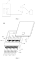
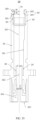
- FIG. 1 is a schematic diagram of an FTTH network.
- a connectorised fiber distribution point (Connectorised Fiber Distribution Point, CFDP) 2 and a fiber distribution box 3 are disposed between a central office (Central Office, CO) 1 and a customer terminal box (Customer Splicing Point, CSP) 4.
- a communications device in the central office 1 is connected to the connectorised fiber distribution point 2 through an optical cable, to distribute a signal to the connectorised fiber distribution point 2.
- the connectorised fiber distribution point 2 transmits the signal to the fiber distribution box 3 through an optical cable, and then the fiber distribution box 3 outputs the signal (transmits the signal through an optical cable) to the customer terminal box 4.
- the communications device may be but is not limited to a fiber access terminal (fiber access terminal, FAT) or a splitting and splicing closure (splitting and splicing closure, SSC).
- FAT fiber access terminal
- SSC splitting and splicing closure
- FIG. 2 is a schematic diagram of a communications device 1000 according to an implementation.
- the communications device 1000 includes a housing 400, an adapter assembly 200A, an indoor connector assembly 300A, and an outdoor connector assembly 100A.
- the adapter assembly 200A is fastened to the housing 400.
- the indoor connector assembly 300A is accommodated inside the housing 400.
- the outdoor connector assembly 100A is located outside the housing 400.
- the outdoor connector assembly 100A and the indoor connector assembly 300A can be connected to the adapter assembly 200A to implement connection and further implement optical signal transmission.
- the indoor connector assembly 300A may be understood as being located in a relatively closed space inside the housing 400, and can be effectively isolated from external dust, water vapor, and the like.
- the outdoor connector assembly 100A may be understood as being located in a relatively open space outside the housing 400, and needs to have better environment adaptability to adapt to a complex and changing external environment.
- the housing 400 includes a box body 401 and a top cover 402 that covers the box body 401.
- the box body 401 is disposed with a plurality of sockets 4011 that are disposed side by side.
- the sockets 4011 may be arranged in one row or a plurality of rows.
- the adapter assembly 200A includes a plurality of fiber adapters 200.
- a quantity of fiber adapters 200 is equal to or less than a quantity of sockets 4011 (a case in which the quantity of fiber adapters 200 is less than the quantity of sockets 4011 means that a part of the sockets can be reserved for other purposes).
- the sockets 4011 may alternatively be disposed on the top cover 402.
- Each fiber adapter 200 can be correspondingly disposed in a position of a corresponding socket 4011.
- an opening adapted to the indoor fiber connector plug 300 and an opening adapted to the outdoor fiber connector plug 100 are disposed at two ends of the fiber adapter 200.
- the indoor fiber connector plug 300 and the outdoor fiber connector plug 100 are inserted into the two openings of the fiber adapter 200.
- ferrules of the indoor fiber connector plug 300 and the outdoor fiber connector plug 100 are connected in the fiber adapter 200, that is, connection between two fibers that need to be connected is implemented, and an optical signal output by a transmit fiber can be coupled to a receive fiber to a maximum extent.
- each indoor fiber connector plug 300 can be inserted into the corresponding fiber adapter 200 from the inside of the housing 400, and each outdoor fiber connector plug 100 can be inserted into the corresponding fiber adapter 200 from the outside of the housing 400, so that each indoor fiber connector plug 300 can be connected to a corresponding outdoor fiber connector plug 100.
- one indoor fiber connector plug 300, one fiber adapter 200, and one outdoor fiber connector plug 100 can together constitute a connector assembly, to implement link transmission of an optical signal.
- the communications device 1000 provided in this application includes a plurality of sockets 4011 arranged in a row or arranged in a plurality of rows.
- the fiber adapters 200 are correspondingly disposed in positions of the sockets 4011, so that more fiber connection ports can be arranged in a limited space and density of fiber adapters disposed in the communications device is improved.
- the dustproof cap 50 may be a part of the housing assembly 20. Alternatively, the fiber connector plug 100 may not include the dustproof cap 50.
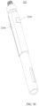
- the sliding member 40 is slidably connected to an outer surface of the housing assembly 20, and is used to lock and unlock the fiber connector plug 100 and a fiber adapter 200.
- the sealing structure 30 is disposed on the outer surface of the housing assembly 20, and is located at a front end of the sliding member 40 in an axial direction. The sealing structure 30 is used to sealingly connect to an inner surface of the fiber adapter 200.
- the front end is an end inserted into the fiber adapter (the end may be understood as an end at which a ferrule is located), and a tail end or a rear end is an end away from the ferrule.
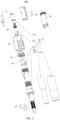
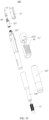
- the main housing 22 includes a mounting member 221, a fastener 222, a main shaft 223, a fastening base 224, a tail sleeve 225, and a heat shrink tube 226.
- the main housing 22 is sleeve-shaped as a whole, and is used to accommodate the fiber 11. All components in the main housing 22 are also sleeve-shaped. In this implementation, six elements are assembled and connected to form the main housing 22. The elements are all connected in a fastened manner. Therefore, some of the elements may be an integrated structure.
- the fastener 222 may be integrally formed at a front end face of the main shaft 223; therefore, the fastener 222 may be considered as a part of the main shaft 223.
- the fiber 11 includes a fiber core 111, a reinforced layer 112 wrapped around the fiber core 111, and an outer layer 113 wrapped around the reinforced layer 112.
- a part of the fiber core 111 extends out of the reinforced layer 112 and is fastened to the ferrule 12.
- a part of the reinforced layer 112 of the fiber is not wrapped by the outer layer.
- a part of the outer layer is also located inside the housing assembly 20.
- the reinforced layer 112 may be made of a metal or non-metal material.
- the metal material of the reinforced layer 112 may be a steel wire.
- the non-metal material of the reinforced layer 112 may be an FRP (fiber reinforced composite material).
- the ferrule 12 includes a front end face 121 and a rear end face 122.
- a front section 123, a middle section 124, and a rear section 125 are sequentially connected between the front end face 121 and the rear end face 122, and both the front section 123 and the rear section 125 have a centrosymmetric structure.
- a shape of the rear section 125 is a cylinder
- a shape of the front section 123 is a combination of a cylinder and a truncated cone.
- the middle section 124 includes a first limiting structure 1241 and a first stop structure 1242.
- the first limiting structure 1241 is located between the first stop structure 1242 and the front section 123.
- the first limiting structure 1241 is used to fit the housing assembly 20, to limit the ferrule 12 in a circumferential direction, that is, prevent the ferrule 12 from rotating relative to the housing assembly 20.
- the first limiting structure 1241 includes a first plane 1243. There may be one, two, or more first planes 1243.
- the first plane 1243 may have a limiting function in the circumferential direction, provided that disposing of the first plane 1243 enables the middle section 124 to be a non-rotary symmetric structure. As shown in FIG. 7 , there are four first planes 1243 spaced apart and symmetrically distributed on an outer surface of the middle section 124.
- the first stop structure 1242 is a columnar structure connected to the first limiting structure 1241.
- the first stop structure 1242 includes a first limiting face 1244, and the first limiting face 1244 faces the front end face 121 of the ferrule 12.
- a quantity of disposed first limiting faces 1244 also corresponds to a quantity of disposed first planes 1243, and the first limiting faces 1244 are vertically connected to the first planes 1243.
- a piece is cut off from an outer surface of a cylindrical entity, and the first plane 1243 and the first limiting face 1244 are simultaneously formed.
- An outer surface of the rear section 125 is used to sleeve the first elastic member 60 (for example, a spring).
- a surface that is of the first stop structure 1242 and that faces the rear section 125 is a positioning face 1245, and the positioning face 1245 is used to abut against the first elastic member 60.
- a fiber core fastening hole 1251 is disposed in the rear section 125. On the rear end face 122, the fiber core fastening hole 1251 forms an opening for inserting the fiber core 111.
- a light-through hole 126 is formed between a bottom of the fiber core fastening hole 1251 and the front end face 121 of the ferrule 12. In the fiber core fastening hole 1251, the bottom is a position directly facing the opening.
- the connection is implemented by using the front end face 121 of the ferrule 12.
- optical signal transmission is implemented between the two fiber connector plugs 100. Therefore, for the fiber connector plug 100, the front end face 121 of the ferrule 12 needs to be protected by the housing assembly 20, to ensure that the front end face 121 of the ferrule 12 is not scratched and ensure quality of light transmission.
- the front cover 21 on the housing assembly 20 can protect the front end face of the ferrule 12.
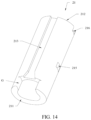
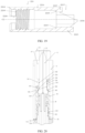
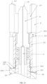
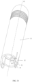
- the front cover 21 is described in detail (described with reference to FIG. 9 to FIG. 16 ) in the following.
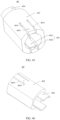
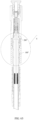
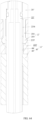
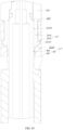
- the front cover 21 is sleeve-shaped and includes a front end face 211 and a rear end face 212.
- the front cover 21 is located at a most front end of the housing assembly 20, and the rear end face 212 of the front cover 21 is used to connect to the main housing 22.
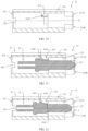
- the front end face 211 of the front cover 21 is flush with the front end face 121 of the ferrule 12.
- the front end face 121 of the ferrule 12 is encircled by an inner surface of the front cover 21, that is, the front end face 121 of the ferrule 12 is retracted into the front cover 21.
- the front end face 211 of the front cover 21 is protrudingly disposed on the front end face 121 of the ferrule 12 in the axial direction. In the axial direction, a distance between the front end face 121 of the ferrule 12 and the front end face 211 of the front cover 21 is L.
- a vertical projection of the front end face 121 of the ferrule 12 on the front cover 21 is located on the front end face 211 of the front cover 21 or the inner surface of the front cover 21, so that the front end face of the ferrule 12 is protected.
- the front end face 211 of the front cover 21 can protect the front end face of the ferrule 12.
- the front cover 21 can protect the front end face of the ferrule in a process of turnover, transportation, and insertion into and removal from the fiber adapter.
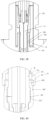
- a slot 217 is formed between the inner surface of the front cover 21 and the ferrule 12, and the slot 217 forms an opening between the front end face 211 of the front cover 21 and the front end face 121 of the ferrule 12.
- the slot 217 is used to fit a ferrule sleeve of the fiber adapter.
- the ferrule when the fiber connector plug is inserted into the fiber adapter, the ferrule is inserted into the ferrule sleeve, the ferrule sleeve is inserted into the slot 217, and one end of the ferrule sleeve needs to extend into the slot 217, that is, an end face of the ferrule sleeve is located in the slot 217 and is disposed opposite to a slot bottom of the slot 217, where the slot bottom of the slot 217 is an end opposite to the opening of the slot 217.
- the front end face 211 includes a first face 211A and a second face 211B, and the first face 211A and the second face 211B are symmetrically disposed on two sides of a central axis of the front cover 21.
- the two notches G1 and G2 may be symmetrically disposed on the two sides of the central axis of the front cover 21. Due to the form of symmetric disposing, force received by the exterior sleeve during the insertion can be relatively even and balanced, overall strength of the outer frame sleeve is high, and a possibility of a connection failure caused by force imbalance can be minimized.
- a notch G is disposed at one end close to the front end face of the front cover 21, so that the front end face 211 of the front cover 21 forms a non-closed continuously extending surface.
- the front end face 211 may be C-shaped, arc-shaped, or semi-circular shaped.
- Disposing of the notch G enables the front end of the fiber connector plug to present a concave-convex shape suitable for insertion.
- the fiber connector plug can better adapt to an internal space of the fiber adapter in comparison with a front end of a fiber connector plug in a flat shape. Therefore, a loose connection caused by a limitation of the internal space of the fiber adapter is avoided, stability and reliability of the insertion are improved, practicability is higher, and an application range is wide.
- the notch G disposed at the front end of the front cover is also advantageous for observation.
- a worker can see at least the front end face of the ferrule when viewing an outer surface of the outer frame sleeve disposed with the notch G. Based on this, when connecting the fiber connection plug to the fiber adapter, the worker can see a position of the ferrule. This facilitates insertion, improves an insertion success rate, prevents the ferrule from suffering a plurality of collisions due to wrong insertion, and prevents the ferrule from being damaged.
- the front end face 211 of the front cover 21 is a closed ring structure, that is, the front end face 211 is not disposed with a notch structure.
- the front end face 211 may be in a circular ring shape, or may be in another shape.
- a contour of an inner edge of the front end face 211 may be in a circular shape
- a contour of an outer edge of the front end face 211 may be in a square shape. The outer contour in the square shape facilitates matching with an internal space of the fiber adapter in a same shape.
- the second plane 2142 is a surface on a side that is of the second limiting structure 214 and that is away from the outer surface of the front cover 21.
- the second plane 2142 is used to fit the first plane 1243 of the first limiting structure 1241 of the ferrule 12.
- the first plane 1243 and the second plane 2142 are not limited to theoretical plane features in this application. It may be understood that the first plane may alternatively be approximately a plane, for example, an arc surface approximate to a plane. Alternatively, a concave-convex structure may be disposed on the first plane and the second plane.
- the mounting member 221 and the front cover 21 are stacked in the radial direction, and the front cover 21 is sleeved over a periphery of the mounting member 221.
- the mounting member 221 includes a mounting member body 2211, an elastic clamping hook 2212, and a second stop structure 2213.
- the elastic clamping hook 2212 and the second stop structure 2213 are formed at a front end of the mounting member body 2211.
- a rear end face 2214 of the mounting member body 2211 is used to be in contact with the main shaft 223.
- the mounting member body 2211 is sleeve-shaped and includes a central axis C2, the second stop structure 2213 protrudes from an inner surface of the mounting member body 2211, and the second stop structure 2213 includes a second limiting face 2215 and a contact face 2216.
- the second limiting face 2215 faces a rear end of the mounting member body 2211, and the contact face 2216 faces the central axis C2 of the mounting member body 2211.
- the second limiting face 2215 is vertically connected to the contact face 2216, and both the second limiting face 2215 and the contact face 2216 are planar.
- the second limiting face 2215 is used to fit the first limiting face 1244 of the first stop structure 1242 of the ferrule 12, and the contact face 2216 is used to fit the first plane 1243 of the first limiting structure 1241 of the ferrule 12.
- the second plane 2142 of the second limiting structure 214 of the front cover 21 is coplanar with a contact face 2216 of one second stop structure 2213, and is disposed opposite to the contact face 2216 of the other second stop structure 2213.
- an outer surface of the mounting member body 2211 is in contact with the inner surface of the front cover 21, and the inner surface of the mounting member body 2211 is in contact with the ferrule 12.
- the elastic clamping hook 2212 is used to fit the hole 215 on the front cover 21 to fasten the mounting member 221 to the front cover 21.
- there are two elastic clamping hooks 2212 symmetrically distributed on the two sides of the central axis C2 of the mounting member body 2211.
- the two second stop structures 2213 are located on sides of the two elastic clamping hooks 2212, and the two second stop structures 2213 are distributed between the two elastic clamping hooks 2212 in the circumferential direction.
- a fastening manner between the mounting member 221 and the front cover 21 is not limited to fastening through a fit between the elastic clamping hook 2212 and the hole 215.
- another fastening manner may be used.
- the mounting member 221 may not be disposed with the elastic clamping hook 2212.
- the mounting member 221 and the front cover 21 may be fastened by using a screw, and the screw passes through the front cover 21 and is fastened in the mounting member 221.
- the mounting member 221 and the front cover 21 are fastened by using glue.
- a clamping hook is disposed on the front cover 21, a clamping groove or a hole is disposed on the mounting member 221, and the mounting member 221 and the front cover 21 are fastened through a fit between the clamping hook and the clamping groove or the hole.
- a second cut 2218 is disposed on the rear end face 2214 of the mounting member body 2211.
- the second cut 2218 forms openings on all of the rear end face 2214, the inner surface, and the outer surface of the mounting member body 2211.
- the second cut 2218 is used to implement positioning between the mounting member 221 and the main shaft 223, position the mounting member 221 and the main shaft 223 in the circumferential direction, and prevent the mounting member 221 from rotating relative to the main shaft 223.
- the rear end face 2214 of the mounting member body 2211 and the rear end face 212 of the front cover 21 are coplanar and jointly form a connecting face S1.
- the connecting face S1 is in contact with the end face of the main shaft 223.
- a structural design in which the connecting face S1 is in contact with the end face of the main shaft 223 is employed, so that the connection between the front cover 21 and the main shaft 223 occupies only a space of the end face of the main shaft 223 and does not extend to an outer surface of the main shaft 223.
- the outer surface of the front cover 21 and the outer surface of the main shaft 223 may be coplanar, or there is a smooth transition.
- the outer surface of the front cover 21 is a cylindrical surface
- the outer surface of the main shaft 223 is also a cylindrical surface.
- the front cover 21 is in contact with the end face of the main shaft 223, the outer surfaces of the two cylinders with a same radial size are in contact to form a complete cylindrical outer surface.
- the connecting face S1 and the end face of the main shaft 223 implement positioning in the circumferential direction by using a cut-bump fitting structure.
- the first cut 216 and the second cut 2218 directly face each other in the radial direction, and are used to implement positioning of the front cover 21 and the mounting member 221 to the main shaft 223.
- a sealing connection may be formed at a joint between the connecting face S1 and the main shaft 223.
- a function of the sealing connection is to isolate an internal space of the main shaft 223 from an external space in a sealing manner. In this way, the fiber core and the ferrule can be protected from erosion by dust, moisture, and the like, the service life of the fiber connector plug is prolonged, and efficiency and quality of light transmission are enhanced.
- the inner surface of the mounting member body 2211 is further disposed with a threaded part 2219, and the threaded part 2219 is used to fasten the fastener 222.
- the fastener 222 is also sleeve-shaped, an external thread 2221 is disposed in a periphery of a front end of the fastener 222, and the front end of the fastener 222 extends into the mounting member 221 and is fastened to the threaded part 2219 on the mounting member 221.
- a rear end of the fastener 222 extends into the main shaft 223 and is fastened to an inner surface of the main shaft 223.
- an elastic clasp arm 2222 is formed at the rear end of the fastener 222.
- the elastic clasp arm 2222 extends along the axial direction.
- a clasp part 2223 is protrudingly disposed on an outer surface of the elastic clasp arm 2222.
- the clasp part 2223 is used to fit a limiting step on the inner surface of the main shaft 223, to fasten the fastener 222 to the main shaft 223.
- Three elastic clasp arms 2222 are disposed at the rear end of the fastener 222, and a gap 2224 is formed between adjacent elastic clasp arms 2222.
- the gap 2224 is formed to enable the elastic clasp arms 2222 to elastically swing in the radial direction.
- a part of the fastener 222 is located inside the main shaft 223, and the other part is located inside the mounting member 221. That is, the fastener 222 is in a fully enclosed state. In a periphery of the fastener 222, the main shaft 223 and the mounting member 221 are connected.
- the fastener 222 may alternatively be partially exposed as an exterior face of the fiber connector plug.
- the fastener 222 is in a sleeve-shaped structure.
- the fastener 222 includes a front end 2225, a rear end 2226, and a middle part 2227 connected between the front end 2225 and the rear end 2226.
- the front end 2225 of the fastener 222 extends into an inner side of the mounting member 221 and is fastened to the mounting member 221.
- the rear end 2226 of the fastener 222 extends into an inner side of the main shaft 223 and is fastened to the main shaft 223.
- the middle part 2227 is located between the front end of the main shaft 223 and a rear end of the mounting member 221. It may also be understood that the middle part 2227 is located between the front end of the main shaft 223 and the rear end of the front cover 21. An outer surface of the middle part 2227 forms the exterior face of the fiber connector plug.
- the front end 2225 is detachably connected to the mounting member 221 in a manner of a fit between a buckle and a hole.
- a buckle is disposed in a periphery of the front end 2225.
- a hole that penetrates the inner surface and the outer surface is disposed on the mounting member 221.
- the buckle of the front end 2225 is accommodated in the hole of the mounting member 221.
- the rear end 2226 is also detachably connected to the main shaft 223 in a manner of a fit between a buckle and a hole.
- a buckle is disposed in a periphery of the rear end 2226.
- a hole that penetrates the inner surface and the outer surface is disposed on the main shaft 223.
- the buckle of the rear end 2226 is accommodated in the hole of the main shaft 223.
- a sealing groove is disposed in a periphery of the middle part 2227 and is used to accommodate a sealing structure 30.
- the sealing groove may not be disposed in the periphery of the middle part 2227, but the sealing groove is disposed on the outer surface of the main shaft 223.
- a sealing structure may also be disposed between the rear end 2226 of the fastener 222 and the main shaft 223.
- a guide structure may also be disposed in the periphery of the middle part 2227.
- the guide structure communicates with or continuously extends to the first guide structure 213 on the front cover 21.
- the guide structure and the first guide structure 213 on the front cover 21 jointly fit the guide key on the fiber adapter.
- a guide structure is disposed in each of the periphery of the middle part 2227 and the periphery of the main shaft 223.
- the two guide structures are disposed on an extension path of the first guide structure 213 on the front cover 21.
- the two guide structures and the first guide structure 213 on the front cover 21 jointly form a guide structure of the fiber connector plug.
- a core element of the main housing 22 is the main shaft 223, and main features of the main shaft 223 are concentrated on a front end face 2231 and the outer surface of the main shaft 223.
- the front end face 2231 of the main shaft 223 is used to in contact with the front cover 21 and the mounting member 221.
- a bump 2232 is protrudingly disposed on the front end face 2231 of the main shaft 223.
- the bump 2232 extends along the radial direction from an inner edge of the front end face 2231 of the main shaft 223 to an outer edge of the front end face 2231 of the main shaft 223.
- a second guide structure 2233, a sealing groove 2234, a locking part 2235, a first sliding guide structure 2236, and a fastening part 2237 are sequentially disposed on the outer surface of the main shaft 223 along the axial direction from the front end to the rear end of the main shaft 223.
- the second guide structure 2233 and the first guide structure 213 (as shown in FIG. 3 ) on the front cover 21 are connected, and jointly fit the guide key on the fiber adapter 200. This can prevent the front cover 21 and the main shaft 223 from rotating relative to each other.
- the second guide structure 2233 may be a groove structure recessed on the outer surface of the main shaft 223, or the second guide structure 2233 penetrates the inner surface and the outer surface of the main shaft 223 (that is, the second guide structure 2233 may be understood as a cut structure disposed on the main shaft 223).
- the second guide structure 2233 may be a structure protrudingly disposed on the outer surface of the main shaft 223.
- a circumferential size and a radial size of the second guide structure 2233 may be the same as a circumferential size and a radial size of the first guide structure 213 respectively.
- the sealing groove 2234 is an arc-shaped groove structure that encircles the outer surface of the main shaft 223.
- the locking part 2235 is located on a side that is of the sealing groove 2234 and that is away from the second guide structure 2233. The following describes the locking part 2235 in detail.
- the integrated structure of the fastener 222 and the main shaft 223 has an advantage of lightness and thinness, where "thin” refers to a radial size, because in the radial direction, the fastener 222 and the main shaft 223 are not assembled and connected in an overlapping manner.
- the front cover 21 is sleeved from one side of the front end of the ferrule 12 to the periphery of the mounting member 221, and the second plane 2142 of the second limiting structure 214 in the front cover 21 is in contact with the first plane 1243 of the first limiting structure 1241 of the ferrule 12.
- the second plane 2142 of the front cover 21 is coplanar with the contact face 2216 of one of the second stop structures 2213 of the mounting member 221.
- the second plane 2142 of the front cover 21 and the contact face 2216 of the other second stop structure 2213 of the mounting member 221 are disposed opposite to each other on two sides of the ferrule 12.
- the elastic clamping hook 2212 on the mounting member 221 fits the hole 215 on the front cover 21, to fasten the front cover 21 and the mounting member 221.
- the bump 2232 on the front end face 2231 of the main shaft 223 extends into the first cut 216 on the rear end face of the front cover 21 to position the front cover 21 and the main shaft 223 in the circumferential direction.
- the rear end face 212 of the front cover 21 is coplanar with the rear end face 2214 of the mounting member 221.
- the first cut 216 directly faces the second cut 2218 in the radial direction, and the bump 2232 on the main shaft 223 fits both the first cut 216 and the second cut 2218.
- the front end face of the sliding member 40 faces the tail end of the main shaft 223 (the fiber needs to pass through the sliding member 40), and the sliding member 40 is sleeved over the outer surface of the main shaft 223.
- the second sliding guide structure 44 on the inner surface of the sliding member 40 fits the first sliding guide structure 2236 on the outer surface of the main shaft 223, so that the sliding member 40 and the main shaft 223 are positioned in the circumferential direction.
- the second sliding guide structure in this implementation is a groove structure.
- a position indicated by a reference numeral 44 in FIG. 6 represents an inner wall of the groove, and the first sliding guide structure 2236 is accommodated in the groove.
- a position between the sliding member 40 and the main shaft 223 is defined in the axial direction through a fit between the second limiting step 4421 of the second limiting part 442 of the sliding member 40 and the first limiting step 22363 of the first limiting part 22362 on the outer surface of the main shaft 223.
- the second elastic member 70 is sleeved over the main shaft 223, and one end of the second elastic member 70 is mounted in a space between the sliding member 40 and the main shaft 223 and abuts against the step positioning face 45 of the inner surface of the sliding member 40.
- the fastening base 224 is mounted to the fastening part 2237 on the main shaft 223, a front end of the fastening base 224 abuts against the other end of the second elastic member 70, and the fastening base 224 partially extends into the space between the sliding member 40 and the main shaft 223.
- the second elastic member 70 is in a compressed state and pushes the sliding member 40 to the first position by using elastic force, that is, a position of a fit between the second limiting step 4421 of the second limiting part 442 of the sliding member 40 and the first limiting step 22363 of the first limiting part 22362 on the outer surface of the main shaft 223.
- the sealing structure 30 is sleeved in the sealing groove 2234, and when the fiber connector plug 100 is inserted into the fiber adapter 200, the sealing ring is sealingly connected between the main shaft 223 and the inner surface of the fiber adapter 200.
- the fiber connector plug 100 provided in this implementation is a fiber connector plug 100 used outdoors, and has a sealing requirement. According to this application, the front end of the main shaft 223 extends into the fiber adapter 200 to implement sealing by using the sealing structure 30, and the tail end of the main shaft 223 sealingly connects the main shaft 223 to the fiber by using the heat shrink tube 226. In this way, only one sealing structure 30 needs to be disposed at the front end of the main shaft 223 to sealingly connect the fiber connector plug 100 to the fiber adapter 200.
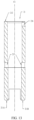
- the fiber adapter 200 includes a body sleeve 201 and a ferrule sleeve 202.
- the ferrule sleeve 202 is connected inside the body sleeve 201.
- the ferrule sleeve 202 and the body sleeve 201 may be an integrated structure.
- the body sleeve 201 includes a first end face 2011 and a second end face 2012.
- a first accommodating space 2013 located on an inner side of the first end face 2011 and a second accommodating space 2014 located on an inner side of the second end face 2012 are formed inside the body sleeve 201.
- a first opening for the first accommodating space 2013 to communicate with the outside is disposed on the first end face 2011.
- a second opening for the second accommodating space 2014 to communicate with the outside is disposed on the second end face 2012.
- a ferrule accommodating space 2022 is disposed in the ferrule sleeve 202, and the ferrule accommodating space 2022 is located between the first accommodating space 2013 and the second accommodating space 2014, and communicates with the first accommodating space 2013 and the second accommodating space 2014.
- the first accommodating space 2013 is used to accommodate one fiber connector plug 100.
- the second accommodating space 2014 is used to accommodate another fiber connector plug 100.
- the ferrule accommodating space 2022 in the ferrule sleeve 202 is used to accommodate ferrules of the two fiber connector plugs.
- the first accommodating space 2013 is used to insert an outdoor fiber connector plug (that is, the fiber connector plug 100 provided in the first embodiment).
- the second accommodating space 2014 is used to insert an indoor fiber connector plug.
- An internal structure of the second accommodating space 2014 and a specific architecture of the indoor fiber connector plug are not limited in this application.
- the body sleeve 201 includes a body part 203 and a second locking structure L2.
- the second locking structure L2 is disposed at one end of the body part 203.
- the second locking structure L2 is located in a first opening position in which the first accommodating space 2013 communicates with the outside.
- the second locking structure L2 includes a clamping groove 204 and an elastic arm 205.
- the elastic arm 205 is connected to one end of the body part 203. In an axial direction, the body part 203 is located between the ferrule sleeve 202 and the elastic arm 205, and the clamping groove 204 is located on an inner surface of the body sleeve 201.
- the elastic arm 205 of the fiber connector plug 100 extends from one end of the body part 203 along the axial direction of the body sleeve 201.
- the elastic arm 205 includes a first section 2051 and a second section 2052.
- the first section is connected between the second section 2052 and the body part 203.
- An outer surface of the elastic arm 205 is a surface that is of the elastic arm 205 and that is away from the first accommodating space 2013.
- a vertical distance R1 from an outer surface of the first section 2051 to a central axis C6 of the body sleeve 201 is greater than a vertical distance R2 from an outer surface of the second section 2052 to the central axis C6 of the body sleeve 201.
- a part of the clamping groove 204 is located on an inner surface of the body part 203, and a part of the clamping groove 204 is located on an inner surface of the elastic arm 205 (specifically, an inner surface of the first section 2051).
- the first section 2051 directly faces the part of the clamping groove 204, and the second section 2052 is located in a periphery of the clamping groove 204.
- the outer surface of the elastic arm 205 is in a stepped shape, that is, a stepped surface is formed between the first section 2051 and the second section 2052.
- an extension direction from the body part 203 to an end that is of the second section 2052 and that is away from the body part 203 is an extension direction of the elastic arm 205
- an included angle A6 is formed between the extension direction of the elastic arm 205 and the axial direction of the body sleeve 201.
- FIG. 34 schematically shows oblique extension of the elastic arm 205 relative to the axial direction.
- the specific oblique angle A6 may be set based on a related feature (that is, a fitting surface) on a sliding member of a specific fiber connector plug.
- an etched structure is disposed on the outer surface of the first section 2051 and/or the outer surface of the second section 2052; or a protruding part is disposed on the outer surface of the elastic arm 205, and the protruding part is used to fit the groove on the sliding member 40 of the fiber connector plug 100.
- the first slot 207 between the body sleeve 201 and the ferrule sleeve 202 fits the front cover 21 of the fiber connector plug 100
- the inner surface of the body sleeve 201 is in contact with and fits the outer surface of the front cover 21
- the guide key 206 is used to fit the first guide structure 213 on the front cover 21, to implement matching between the fiber adapter 200 and the fiber connector plug 100.
- the structure of the fiber adapter 200 is simplified, alignment of the fiber connector plug 100 inserted into the fiber adapter 200 is implemented by using the first slot 207 and the inner surface of the body sleeve 201, and a radial size may be designed to match the front cover 21 of the fiber connector plug 100. Therefore, the fiber connector plug 100 has an advantage of a small size.
- the fiber adapter 200 provided in this application further includes a ceramic sleeve 208, and the ceramic sleeve 208 is mounted inside the ferrule sleeve 202.
- the ceramic sleeve 208 is disposed with a cut 2082.
- the cut 2082 extends from one end of the ceramic sleeve 208 to the other end along the axial direction. Disposing of the cut 2082 makes a radial size of the ceramic sleeve 208 adjustable, so that a close fit between the ceramic sleeve 208 and the ferrule sleeve 202 can be implemented.
- An internal space of the ceramic sleeve 208 is used to accommodate the ferrule.
- FIG. 36 is a schematic cross-sectional diagram after the fiber connector plug 100 is inserted into the corresponding fiber adapter 200 according to a first implementation of this application.
- FIG. 37 is an enlarged schematic diagram of a part I in FIG. 36
- FIG. 38 is an enlarged schematic diagram of a part II in FIG. 36 .
- FIG. 39 is another schematic cross-sectional diagram after the fiber connector plug 100 is inserted into the corresponding fiber adapter 200 according to the first implementation.
- FIG. 40 is an enlarged schematic diagram of a part III in FIG. 39 .
- the sealing structure 30 sealingly connects the fiber connector plug 100 to the corresponding fiber adapter 200.
- the front cover 21 of the fiber connector plug 100 is inserted into the slot 207, the ferrule 12 is inserted into the ferrule sleeve 202 and is encircled by the ceramic sleeve 208, and the outer surface of the front cover 21 is in contact with the inner surface of the body sleeve 201.
- FIG. 36 shows a locked state after the fiber connector plug 100 is inserted into the fiber adapter 200.
- the sliding member 40 is located in the first position, and the locking part 2235 of the fiber connector plug fits the clamping groove 204 of the fiber adapter.
- the first area 421 of the fitting surface 42 abuts against the first section 2051 of the elastic arm 205, and the second area 422 of the fitting surface 42 abuts against the second section 2052 of the elastic arm 205, to implement a two-step locking structure.
- FIG. 39 shows an unlocked state after the fiber connector plug 100 is inserted into the fiber adapter 200.
- the sliding member 40 is located in the second position, and the first area 421 of the fitting surface 42 is located in a periphery of the second section 2052 of the elastic arm 205.
- the first area 421 and the second section 2052 are detached from each other, a gap is formed between the first area 421 and the second section 2052, and the second area 422 directly faces the outer surface of the main shaft 223 of the fiber connector plug 100.
- a gap is formed between the fitting surface 42 and the elastic arm 205, and the elastic arm 205 may be opened. Therefore, in this case, although the locking part 2235 of the fiber connector plug is located in the clamping groove 204 of the fiber adapter, the fiber connector plug 100 can still be pulled out of the fiber adapter 200.
- FIG. 41 is a three-dimensional diagram of a fiber connector plug 100' provided in the second embodiment.
- FIG. 42 is a three-dimensional exploded diagram of the fiber connector plug 100' provided in the second embodiment.
- the fiber connector plug 100' includes a fiber 11', a ferrule 12', a front cover 21', a mounting member 221', a main shaft 223', a tail sleeve 225', a heat shrink tube 226', a sealing structure 30', a sliding member 40', and a first elastic member 60'.
- a locking part 2235' is disposed on the main shaft 223', and the locking part 2235' and the sliding member 40' form a first locking structure L1'.
- a difference between the fiber connector plug 100' provided in the second embodiment and the fiber connector plug 100 provided in the first embodiment lies in a structure of the main shaft 223' and a structure of the sliding member 40'.
- the following describes in detail a structural feature that is of the main shaft 223' and that is different from a structural feature of the main shaft in the fiber connector plug 100 provided in the first embodiment.
- the fiber connector plug 100' provided in this implementation does not include the fastener 222 independent of the main shaft in the fiber connector plug 100 provided in the first embodiment. It may be understood that in this implementation, a structural feature similar to a fastener function is integrated on the main shaft 223'. To be specific, a protruding ring structure 222' integrally formed to an inner surface of the main shaft 223' is disposed at an inner edge of a front end face 2231' of the main shaft 223', and an outer surface of the protruding ring structure 222' is disposed with a screw thread for connecting the mounting member 221'.
- the locking part 2235' disposed on an outer surface of the main shaft 223' is located on a side that is of a sealing groove 2234' and that is away from the front end face 2231'.
- the locking part 2235' includes an elastic arm 22351 and a clamping block 22352.
- One end of the elastic arm 22351 is fastened to the outer surface of the main shaft 223'.
- one end of the elastic arm 22351 and the main shaft 223' are an integrated structure. Only one end of the elastic arm 22351 is connected to the main shaft 223', a remaining part of the elastic arm is an architecture disconnected from and opposite to the main shaft 223', and a gap 22353 is disposed between the elastic arm 22351 and the main shaft 223'.
- the clamping block 22352 is fastened to the other end of the elastic arm 22351, an end at which the elastic arm 22351 is connected to the main shaft 223' is a connection end, and the clamping block 22352 is located in a position that is on the elastic arm 22351 and that is away from the connection end.
- the clamping block 22352 protrudes from a surface that is of the elastic arm 22351 and that is away from the main shaft 223'.
- a clamping structure 701 is further disposed on the outer surface of the main shaft 223', and the clamping structure 701 is used to fit the sliding member 40', to limit the sliding member 40' to a first position.
- the clamping structure 701 is a limiting block protrudingly disposed on the outer surface of the main shaft 223'.
- the sliding member 40' includes a sliding body 403 slidably connected to the main shaft 223' and a stop structure 404 connected to one end of the sliding body 403.
- the sliding body 403 is sleeve-shaped.
- the stop structure 404 extends from an inner surface of one end of the sliding body 403.
- the stop structure 404 is in an arc-shaped sheet-like structure, and the stop structure 404 can slide into the gap 22353.
- the sliding member 40' includes a sliding positioning structure 405.
- the sliding positioning structure 405 includes a connection part 4051 connected to the sliding body 403 and a bump structure 4052 protrudingly disposed on the connection part 4051.
- the connection part 4051 is formed by disposing a pair of strip-shaped slits 4031 on the sliding body 403. Disposing of the slits 4031 enables the connection part 4051 to easily make radial elastic deformation under an action of external force.
- the bump structure 4052 is used to fit the clamping structure 701 on the main shaft. Specifically, when the bump structure 4052 is clamped in the limiting groove 702, the sliding member 40' can be limited to the first position.
- the fiber adapter 200' includes a body sleeve 201' and a ferrule sleeve 202', and a second locking structure L2' is disposed on the body sleeve 201'.
- a difference between the fiber adapter 200' and the fiber adapter 200 lies in that the second locking structure L2' of the fiber adapter 200' is different from the second locking structure L2 of the fiber adapter 200.
- the second locking structure L2' is a clamping groove formed on an inner surface of the body sleeve 201'.
- the clamping groove includes a limiting groove 2016 recessed on an inner surface of the body part and a groove or hole 2017 located at a bottom of the limiting groove 2016.
- the limiting groove 2016 is used to fit the elastic arm 22351 of the locking part 2235' on the fiber connector plug 100'.
- the groove or hole 2017 is used to fit the clamping block 22352 of the locking part 2235' on the fiber connector plug 100'.
- FIG. 51 is a schematic diagram of a state in which the fiber connector plug 100' is inserted into the fiber adapter 200'.
- FIG. 52 is an enlarged schematic diagram of a part IV in FIG. 51 .
- FIG. 52 is a schematic diagram of a state of locking between the fiber connector plug 100' and the fiber adapter 200'.
- FIG. 53 is a schematic diagram of a state of unlocking between the fiber connector plug 100' and the fiber adapter 200'.
- the elastic arm 22351 of the locking part 2235' is located in the limiting groove 2016, and the clamping block 22352 is clamped into the groove or hole 2017.
- the sliding member 40' slides to cause the stop structure 404 to slide into the gap 22353.
- the stop structure 404 can abut against the elastic arm 22351, to lock the clamping block 22352 in the groove or hole 2017, so that locking between the fiber connector plug 100' and the corresponding fiber adapter 200' is implemented.
- the sliding member 40' slides to cause the stop structure 404 to leave the gap 22353.
- the elastic arm 22351 swings into the gap 22353 under an action of elastic deformation of the elastic arm 22351, so that the clamping block 22352 leaves the groove or hole 2017, to implement unlocking.
- FIG. 54 is a three-dimensional diagram of a fiber connector plug 100" provided in the third embodiment.
- FIG. 55 is a three-dimensional exploded diagram of the fiber connector plug 100" provided in the third embodiment.
- the fiber connector plug 100" includes a fiber 11", a ferrule 12", a front cover 21", a mounting member 221", a main shaft 223", a tail sleeve 225", a heat shrink tube 226", a sealing structure 30", a sliding member 40", and a first elastic member 60".
- a locking part 2235" is disposed on the main shaft 223", and the locking part 2235" and the sliding member 40" form a first locking structure L1".
- a difference between the fiber connector plug 100" provided in the third embodiment and the fiber connector plug 100' provided in the second embodiment lies in a structure of the main shaft 223", a structure of the locking part 2235", and a structure of the sliding member 40".
- a difference between the main shaft 223" provided in this implementation and the main shaft 223' of the fiber connector plug 100' provided in the second embodiment lies in that no locking part of an integrated structure is disposed on the main shaft 223".
- the locking part 2235" and the main shaft 223" are a split structure, and a connection part 22354 for connecting the locking part 2235" is disposed on an outer surface of the main shaft 223".
- the connection part 22354 is a bump structure protrudingly disposed on the outer surface of the main shaft 223".
- a specific shape of the connection part 22354 may be a square, a circle, a triangle, a polygon, or the like. This is not limited in this application.
- the locking part 2235" is in a sleeve-shaped structure, and an inner surface of the locking part 2235" is disposed with a positioning groove 22355, a locking groove 22356, and a hole 22357.
- the positioning groove 22355 is used to fit the connection part 22354 on the outer surface of the main shaft 223" to fasten the locking part 2235" to the main shaft 223".
- the hole 22357 is located at a bottom of the locking groove 22356, and the hole 22357 is in a through-hole structure, so that the inner surface of the locking part 2235" communicates with an outer surface of the locking part 2235".
- An extension direction of the locking groove 22356 is an axial direction of the locking part 2235", and an opening of the locking groove 22356 is formed at one end face of the locking part 2235".
- a structure of the sliding member 40" provided in this implementation may be the same as a structure of the sliding member 40' in the fiber connector plug 100' provided in the second embodiment, and the sliding member 40" is slidably connected to the main shaft 223".
- the sliding member 40" includes a sliding body 403' and a stop structure 404' connected to one end of the sliding body 403'.
- the stop structure 404' can move into the accommodating space and abut against the second locking structure of the fiber adapter.
- the fiber adapter 200" includes a body sleeve 201" and a ferrule sleeve 202", and a second locking structure L2" is disposed on the body sleeve 201".
- a difference between the fiber adapter 200" and the fiber adapter 200 lies in that the second locking structure L2" of the fiber adapter 200" is different from
- the second locking structure L2" includes a buckle part 2019 and a connection section 2018.
- the connection section 2018 is connected between the buckle part 2019 and an end face 2011" of the body sleeve 201".
- the buckle part 2019 is protrudingly disposed on a surface that is of the connection section 2018 and that is away from a central axis of the body sleeve 201".
- the connection section 2018 is used to extend into an accommodating space between the locking arm and the main shaft 223" on the fiber connector plug 100".
- the connection section 2018 is used to fit the locking groove 22356, and the buckle part 2019 is used to fit the hole 22357.
- FIG. 63 is a schematic diagram of a state in which the fiber connector plug 100" is inserted into the fiber adapter 200".
- FIG. 64 is an enlarged schematic diagram of a part V in FIG. 63 .
- FIG. 64 is a schematic diagram of a state of locking between the fiber connector plug 100" and the fiber adapter 200".
- FIG. 65 is a schematic diagram of a state of unlocking between the fiber connector plug 100" and the fiber adapter 200".
- the second locking structure L2" of the fiber adapter 200" is aligned, to form an opening position of the locking groove 22356 on an end face of with the locking part 2235".
- the fiber connector plug 100" is inserted into the fiber adapter 200", so that the connection section 2018 extends into the locking groove 22356 and that the buckle part 2019 is located in the position of the hole 22357.
- the sliding member 40" slides to cause the stop structure 404' to slide into a gap between the connection section 2018 and the main shaft 223". In this state, the stop structure 404' can abut against the connection section 2018, to lock the buckle part 2019 in the hole 22357, so that locking between the fiber connector plug 100" and the corresponding fiber adapter 200" is implemented.
- the sliding member 40" slides to cause the stop structure 404' to leave the gap between the connection section 2018 and the main shaft 223".
- the connection section 2018 swings toward one side of the main shaft 223" under an action of elastic deformation of the connection section 2018, so that the buckle part 2019 can be detached from the hole 22357, to implement unlocking.
Landscapes
- Physics & Mathematics (AREA)
- General Physics & Mathematics (AREA)
- Optics & Photonics (AREA)
- Mechanical Coupling Of Light Guides (AREA)
- Connector Housings Or Holding Contact Members (AREA)
Claims (15)
- Glasfaserstecker (100), Folgendes umfassend:eine Glasfaser (11);eine Hülse (12), die an einem vorderen Ende der Glasfaser (11) befestigt ist;ein Hauptgehäuse (22), das muffenförmig ist und über einen Umfang der Glasfaser (11) vermufft ist; undeine vordere Abdeckung (21), die an einem Ende des Hauptgehäuses (22) befestigt ist und die Hülse (12) umgibt, wobei eine Endfläche, die von der Hülse (12) ist und die von der Glasfaser (11) entfernt ist, eine vordere Endfläche der Hülse (12) ist, und eine Endfläche, die von der vorderen Abdeckung (21) ist und die von dem Hauptgehäuse (22) entfernt ist, eine vordere Endfläche der vorderen Abdeckung (21) ist; die vordere Endfläche der Hülse (12) bündig mit der vorderen Endfläche der vorderen Abdeckung (21) ist oder, in einer axialen Richtung, die vordere Endfläche der Hülse (12) zwischen der vorderen Endfläche der vorderen Abdeckung (21) und einer hinteren Endfläche der vorderen Abdeckung (21) angeordnet ist, wobei die hintere Endfläche der vorderen Abdeckung (21) eine Endfläche ist, die von der vorderen Abdeckung (21) ist und dem Hauptgehäuse (22) zugewandt ist; zwischen der vorderen Abdeckung (21) und der Hülse (12) ein Schlitz (217) ausgebildet ist und der Schlitz (217) verwendet wird, um eine Hülsenmuffe (202) eines Glasfaseradapters (200) aufzunehmen, so dass eine Endfläche der Hülsenmuffe (202) in dem Schlitz (217) angeordnet ist; und die Hülse (12) verwendet wird, um in die Hülsenmuffe (202) eingeführt zu werden;wobei eine erste Führungsstruktur (213) auf einer Außenfläche der vorderen Abdeckung (21) angeordnet ist und die erste Führungsstruktur (213) verwendet wird, um zu einem Führungsschlüssel (206) auf dem Glasfaseradapter (200) zu passen;wobei eine zweite Führungsstruktur (2233) auf einer Außenfläche des Hauptgehäuses (22) angeordnet ist und die zweite Führungsstruktur (2233) und die erste Führungsstruktur (213) verbunden sind und gemeinsam verwendet werden, um zu dem Führungsschlüssel (206) auf dem Glasfaseradapter (200) zu passen;wobei die zweite Führungsstruktur (2233) eine Nutstruktur, eine Schnittstruktur oder eine Protrusionsstruktur ist;wobei das Hauptgehäuse (22) einen Hauptschaft (223) und ein Montageelement (221) umfasst, die beide muffenförmig sind, und das Montageelement (221) mit einem Ende des Hauptschafts (223) verbunden ist, das der vorderen Abdeckung (21) zugewandt ist; eine erste Anschlagstruktur (1242) auf einer Außenfläche der Hülse (12) angeordnet ist, das Montageelement (221) einen Montageelementkörper (2211) und eine zweite Anschlagstruktur (2213) umfasst und die zweite Anschlagstruktur (2213) an einem vorderen Ende des Montageelementkörpers (2211) angeordnet ist und aus einer Innenfläche des Montageelementkörpers (2211) vorsteht; und ein Teil der Hülse (12) im Inneren des Montageelements (221) untergebracht ist, die erste Anschlagstruktur (1242) zu der zweiten Anschlagstruktur (2213) passt, um zu verhindern, dass sich die Hülse (12) aus dem vorderen Ende des Montageelementkörpers (2211) aus dem Montageelement (221) bewegt, und die vordere Abdeckung (21) über einer Außenfläche des Montageelements (221) vermufft ist und an dem Befestigungselement (221) befestigt ist; undwobei ein hinteres Ende des Glasfasersteckers (100) ein Ende des Glasfasersteckers (100) ist, das der Hülse (12) abgewandt ist;dadurch gekennzeichnet, dass eine hintere Endfläche (2214) des Montageelementkörpers (2211) und die hintere Endfläche (212) der vorderen Abdeckung (21) koplanar sind und gemeinsam eine Verbindungsfläche (S1) ausbilden und die Verbindungsfläche (S1) in Kontakt mit einer Endfläche des Hauptschafts (223) ist.
- Glasfaserstecker (100) nach Anspruch 1, wobei sich die erste Führungsstruktur (213) entlang der axialen Richtung ausdehnt.
- Glasfaserstecker (100) nach Anspruch 1 oder 2, wobei die erste Führungsstruktur (213) in einer radialen Richtung eine Schlitzstruktur ist, die auf der Außenfläche der vorderen Abdeckung (21) angeordnet ist, die erste Führungsstruktur eine Innenfläche und die Außenfläche der vorderen Abdeckung (21) durchdringt oder die erste Führungsstruktur (213) vorstehend auf der Außenfläche der vorderen Abdeckung (21) angeordnet ist.
- Glasfaserstecker (100) nach einem der Ansprüche 1 bis 3, wobeidie vordere Endfläche der vorderen Abdeckung (21) in einer geschlossenen Ringstruktur ist;eine Aussparung (G) an einem Ende angeordnet ist, das von der vorderen Abdeckung (21) ist und das nahe der vorderen Endfläche der vorderen Abdeckung (21) ist, so dass die vordere Endfläche der vorderen Abdeckung (21) eine nicht geschlossene, sich kontinuierlich ausdehnende Oberfläche ausbildet; oderzwei Aussparungen (G1, G2), die einander entgegengesetzt sind, an einem Ende angeordnet sind, das von der vorderen Abdeckung (21) ist und das nahe der vorderen Endfläche der vorderen Abdeckung (21) ist, so dass die vordere Endfläche der vorderen Abdeckung (21) zwischen den beiden Aussparungen (G1, G2) ausgebildet ist.
- Glasfaserstecker (100) nach einem der Ansprüche 1 bis 4, wobei eine erste Begrenzungsstruktur (1241) auf einer Oberfläche der Hülse (12) angeordnet ist, eine zweite Begrenzungsstruktur (214) auf der Innenfläche der vorderen Abdeckung (21) angeordnet ist und die erste Begrenzungsstruktur (1241) zu der zweiten Begrenzungsstruktur (214) passt, um zu verhindern, dass sich die Hülse (12) und die vordere Abdeckung (21) relativ zueinander drehen.
- Glasfaserstecker (100) nach Anspruch 5, wobei die erste Begrenzungsstruktur (1241) eine erste Ebene (1243) umfasst, die zweite Begrenzungsstruktur (214) vorstehend auf der Innenfläche der vorderen Abdeckung (21) angeordnet ist, die zweite Begrenzungsstruktur (214) eine zweite Ebene (2142) umfasst, die der Hülse (12) zugewandt ist, und die erste Ebene (1243) in Kontakt mit der zweiten Ebene (2142) ist.
- Glasfaserstecker (100) nach einem der Ansprüche 1 bis 6, wobei das Montageelement (221) weiterhin einen elastischen Klemmhaken (2212) umfasst, der elastische Klemmhaken (2212) am vorderen Ende des Montageelementkörpers (2211) ausgebildet ist, die vordere Abdeckung (21) mit einer Klemmnut oder einem Loch angeordnet ist und der elastische Klemmhaken (2212) zu der Klemmnut oder dem Loch passt, um das Montageelement (221) an der vorderen Abdeckung (21) zu befestigen.
- Glasfaserstecker (100) nach einem der Ansprüche 1 bis 7, wobei eine Positionierungsstruktur an einer Verbindung zwischen der Verbindungsfläche (S1) und einer vorderen Endfläche des Hauptschafts (223) angeordnet ist; und die Positionierungsstruktur verwendet wird, um: das Hauptgehäuse (22) und die vordere Abdeckung (21) in einer tangentialen Richtung zu positionieren und/oder das Hauptgehäuse (22) und das Montageelement (221) in einer tangentialen Richtung zu positionieren.
- Glasfaserstecker (100) nach Anspruch 8, wobei ein erster Schnitt (216) auf der hinteren Endfläche der vorderen Abdeckung (21) angeordnet ist, ein zweiter Schnitt (2218) auf der hinteren Endfläche des Montageelementkörpers (2211) angeordnet ist, der erste Schnitt (216) und der zweite Schnitt (2218) in der radialen Richtung einander entgegengesetzt sind, ein Höcker (2232) auf der Endfläche des Hauptschafts (223) angeordnet ist und der Höcker (2232) zu dem ersten Schnitt (216) und dem zweiten Schnitt (2218) passt.
- Glasfaserstecker (100) nach einem der Ansprüche 1 bis 9, wobei eine Dichtungsstruktur (30) und eine erste Verriegelungsstruktur (L1) auf der Außenfläche des Hauptgehäuses (22) angeordnet sind; und entlang der axialen Richtung die Dichtungsstruktur (30) zwischen der vorderen Abdeckung (21) und der ersten Verriegelungsstruktur (L1) angeordnet ist, die erste Verriegelungsstruktur (L1) verwendet wird, um zu einer zweiten Verriegelungsstruktur (L2) des Glasfaseradapters (200) zu passen, und die Dichtungsstruktur (30) zur dichtenden Verbindung einer Innenfläche des Glasfaseradapters (200) verwendet wird.
- Glasfaserstecker (100) nach einem der Ansprüche 1 bis 10, wobei der Hauptschaft (223) ein vorderes Ende und ein hinteres Ende umfasst, die einander entgegengesetzt sind, das vordere Ende des Hauptschafts (223) mit der vorderen Abdeckung (21) verbunden ist, der Hauptschaft (223) die Glasfaser (11) aufnimmt und das hintere Ende an der Glasfaser (11) befestigt ist; und das hintere Ende mit einem Durchgangsloch (2238) angeordnet ist, das Durchgangsloch (2238) eine Außenfläche und eine Innenfläche des Hauptschafts (223) durchdringt und das Durchgangsloch (2238) verwendet wird, um Klebstoff in eine Lücke zwischen der Glasfaser (11) und der Innenfläche des Hauptschafts (223) zu füllen.
- Glasfaserstecker (100) nach Anspruch 11, wobei die Glasfaser (11) einen Glasfaserkern (111), eine verstärkte Schicht (112), die um den Glasfaserkern (111) gewickelt ist, und eine äußere Schicht (113) umfasst, die um die verstärkte Schicht (112) gewickelt ist; ein Teil des Glasfaserkerns (111) sich aus der verstärkten Schicht (112) ausdehnt und an der Hülse (12) befestigt ist und ein Teil der verstärkten Schicht (112) nicht von der äußeren Schicht umwickelt ist; und der Klebstoff verwendet wird, um die verstärkte Schicht (112) an dem Hauptschaft (223) zu befestigen.
- Steckeranordnung (100A), die den Glasfaserstecker (100) nach einem der Ansprüche 1 bis 12 und einen Glasfaseradapter (200) umfasst;
wobei der Glasfaseradapter (200) eine Körpermuffe (201) und eine Hülsenmuffe (202) umfasst, wobei die Hülsenmuffe (202) im Inneren der Körpermuffe (201) verbunden ist und ein erster Aufnahmeraum (2013), der mit einem Innenraum der Hülsenmuffe (202) in Verbindung steht, im Inneren der Körpermuffe (201) angeordnet ist; der erste Aufnahmeraum (2013) verwendet wird, um den Glasfaserstecker (100) aufzunehmen, und die Hülsenmuffe (202) verwendet wird, um die Hülse (12) des Glasfasersteckers (100) aufzunehmen; und eine Innenfläche der Körpermuffe (201) verwendet wird, um in Kontakt mit der Außenfläche der vorderen Abdeckung (21) des Glasfasersteckers (100) zu sein, ein erster Schlitz (207) zwischen der Körpermuffe (201) und der Hülsenmuffe (202) ausgebildet ist und der erste Schlitz (207) verwendet wird, um einen Teil der vorderen Abdeckung (21) aufzunehmen. - Steckeranordnung (100A) nach Anspruch 13, wobei ein Führungsschlüssel (206) auf der Innenfläche der Körpermuffe (201) angeordnet ist, eine Ausdehnungsrichtung des Führungsschlüssels (206) gleich einer Ausdehnungsrichtung einer zentralen Achse der Hülsenmuffe (202) ist und der Führungsschlüssel (206) verwendet wird, um zu der ersten Führungsstruktur (213) auf der vorderen Abdeckung (21) des Glasfasersteckers (100) zu passen.
- Steckeranordnung (100A) nach Anspruch 13, wobei die Körpermuffe (201) ein erstes Ende, ein zweites Ende und ein Körperteil (203) umfasst, das zwischen dem ersten Ende und dem zweiten Ende verbunden ist; und die Hülsenmuffe (202) im Inneren des Körperteils (203) verbunden ist, eine zweite Verriegelungsstruktur (L2) an dem ersten Ende angeordnet ist, die zweite Verriegelungsstruktur (L2) verwendet wird, um zu der ersten Verriegelungsstruktur (L1) des Glasfasersteckers (100) zu passen, und eine Innenfläche des Körperteils (203) dichtend mit der Dichtungsstruktur (30) des Glasfasersteckers (100) verbunden ist.
Applications Claiming Priority (2)
| Application Number | Priority Date | Filing Date | Title |
|---|---|---|---|
| CN202010881525.6A CN112068257B (zh) | 2020-08-27 | 2020-08-27 | 光纤连接器插头、光纤适配器、连接器组件及通信设备 |
| PCT/CN2021/082426 WO2022041707A1 (zh) | 2020-08-27 | 2021-03-23 | 光纤连接器插头、光纤适配器、连接器组件及通信设备 |
Publications (3)
| Publication Number | Publication Date |
|---|---|
| EP4191301A1 EP4191301A1 (de) | 2023-06-07 |
| EP4191301A4 EP4191301A4 (de) | 2024-01-17 |
| EP4191301B1 true EP4191301B1 (de) | 2025-06-25 |
Family
ID=73659570
Family Applications (1)
| Application Number | Title | Priority Date | Filing Date |
|---|---|---|---|
| EP21859556.9A Active EP4191301B1 (de) | 2020-08-27 | 2021-03-23 | Glasfaserstecker, glasfaseradapter, steckeranordnung und kommunikationsvorrichtung |
Country Status (16)
| Country | Link |
|---|---|
| US (1) | US12481104B2 (de) |
| EP (1) | EP4191301B1 (de) |
| JP (1) | JP7538336B2 (de) |
| KR (1) | KR102829746B1 (de) |
| CN (1) | CN112068257B (de) |
| AR (1) | AR123367A1 (de) |
| BR (1) | BR112023003479A2 (de) |
| CA (1) | CA3193296A1 (de) |
| CL (1) | CL2023000568A1 (de) |
| CO (1) | CO2023003294A2 (de) |
| ES (1) | ES3040121T3 (de) |
| MX (1) | MX2023002354A (de) |
| PE (1) | PE20230954A1 (de) |
| SA (1) | SA523442713B1 (de) |
| WO (1) | WO2022041707A1 (de) |
| ZA (1) | ZA202303172B (de) |
Families Citing this family (9)
| Publication number | Priority date | Publication date | Assignee | Title |
|---|---|---|---|---|
| CN112068257B (zh) | 2020-08-27 | 2025-08-15 | 华为技术有限公司 | 光纤连接器插头、光纤适配器、连接器组件及通信设备 |
| CN112946829B (zh) * | 2021-02-25 | 2022-09-09 | 中航光电科技股份有限公司 | 一种插头连接器及连接器组件 |
| CN113093346A (zh) * | 2021-03-01 | 2021-07-09 | 华为技术有限公司 | 光缆组件及光纤连接器 |
| WO2023043917A1 (en) * | 2021-09-17 | 2023-03-23 | Commscope Technologies Llc | Converters for fiber optic connectors |
| CN114911010A (zh) * | 2022-04-29 | 2022-08-16 | 深圳市埃立康科技有限公司 | 单芯光纤适配器和光纤快接组件 |
| WO2023207025A1 (zh) * | 2022-04-29 | 2023-11-02 | 深圳市埃立康科技有限公司 | 单芯光纤适配器和光纤快接组件 |
| CN114815079A (zh) * | 2022-05-05 | 2022-07-29 | 通天电子科技(东莞市)有限公司 | 一种连接器 |
| CN117691400B (zh) * | 2023-12-20 | 2024-07-09 | 江苏正迪微波技术有限公司 | 一种便于组装插接的同轴连接器 |
| CN118295078B (zh) * | 2024-06-06 | 2024-08-23 | 深圳市鹏大光电技术有限公司 | 一种光纤连接器的适配组件 |
Family Cites Families (23)
| Publication number | Priority date | Publication date | Assignee | Title |
|---|---|---|---|---|
| US5815618A (en) * | 1996-06-07 | 1998-09-29 | Molex Incorporated | Adaptor for interconnecting optical fibers |
| JP2007121599A (ja) * | 2005-10-27 | 2007-05-17 | Furukawa Electric Co Ltd:The | 光コネクタ |
| BRPI0807941A2 (pt) * | 2007-02-16 | 2014-07-01 | 3M Innovative Proprietes Company | Conector de fibra ótica de preensão à distância |
| CN101657749B (zh) * | 2007-04-20 | 2014-01-01 | 胡贝尔和茹纳股份公司 | 光连接器 |
| CN102520489B (zh) | 2012-01-11 | 2016-04-13 | 深圳日海通讯技术股份有限公司 | 一种光纤连接器及其装配方法 |
| BR112016010663B1 (pt) | 2013-11-12 | 2019-03-26 | Huawei Technologies Co., Ltd. | Junta de fibra óptica, adaptador de fibra óptica e conector de fibra óptica |
| JP2015206912A (ja) * | 2014-04-21 | 2015-11-19 | オリンパス株式会社 | 光ファイバの接続アダプタおよび内視鏡装置 |
| WO2016136592A1 (ja) * | 2015-02-23 | 2016-09-01 | Seiオプティフロンティア株式会社 | 光コネクタプラグ、光コネクタ用レセプタクル、および光コネクタ接続構造 |
| JP6671847B2 (ja) * | 2015-03-06 | 2020-03-25 | 株式会社フジクラ | 光コネクタ及びコネクタ付き光ケーブル |
| WO2016143202A1 (ja) * | 2015-03-06 | 2016-09-15 | 株式会社フジクラ | プラグ側光コネクタ及び光コネクタシステム |
| CN111065946B (zh) * | 2017-06-28 | 2023-08-18 | 康宁研究与开发公司 | 具有键接连接端口和固定特征的多端口件和其他装置及其制造方法 |
| JP7047314B2 (ja) * | 2017-10-04 | 2022-04-05 | 住友電気工業株式会社 | 光コネクタおよび光接続構造 |
| CN207965231U (zh) * | 2017-11-14 | 2018-10-12 | 烽火通信科技股份有限公司 | 一种光纤连接头、光纤连接器插座和光纤连接组件 |
| CN207965229U (zh) * | 2018-03-30 | 2018-10-12 | 烽火通信科技股份有限公司 | 一种光纤连接头和光纤连接组件 |
| CN110146958B (zh) * | 2019-05-07 | 2023-07-28 | 宁波余大通信技术有限公司 | 通信配线类转换模块单元及单元盒 |
| CN110542952B (zh) | 2019-07-26 | 2021-05-18 | 华为技术有限公司 | 一种光纤连接头以及光纤连接器 |
| CN110542925B (zh) | 2019-09-02 | 2020-07-28 | 吉林大学 | 一种基于峰值包络线的地震数据尖峰噪声识别及压制方法 |
| CN111308615B (zh) * | 2020-02-19 | 2021-10-01 | 华为技术有限公司 | 光纤连接器插头、光纤适配器和光纤连接器 |
| CN114488416A (zh) * | 2020-08-27 | 2022-05-13 | 华为技术有限公司 | 光纤连接器插头、光纤适配器、连接器组件及通信设备 |
| CN112068257B (zh) * | 2020-08-27 | 2025-08-15 | 华为技术有限公司 | 光纤连接器插头、光纤适配器、连接器组件及通信设备 |
| CN213182120U (zh) * | 2020-08-27 | 2021-05-11 | 华为技术有限公司 | 光纤连接器插头、光纤适配器、连接器组件及通信设备 |
| CN112051644B (zh) * | 2020-08-31 | 2022-12-30 | 华为技术有限公司 | 光纤适配器、光纤连接器插头、连接器组件及通信设备 |
| CN114545561A (zh) * | 2020-10-29 | 2022-05-27 | 华为技术有限公司 | 光纤连接器插头组件、光纤连接器组件及通信设备 |
-
2020
- 2020-08-27 CN CN202010881525.6A patent/CN112068257B/zh active Active
-
2021
- 2021-03-23 PE PE2023000737A patent/PE20230954A1/es unknown
- 2021-03-23 MX MX2023002354A patent/MX2023002354A/es unknown
- 2021-03-23 KR KR1020237009930A patent/KR102829746B1/ko active Active
- 2021-03-23 WO PCT/CN2021/082426 patent/WO2022041707A1/zh not_active Ceased
- 2021-03-23 CA CA3193296A patent/CA3193296A1/en active Pending
- 2021-03-23 JP JP2023513329A patent/JP7538336B2/ja active Active
- 2021-03-23 BR BR112023003479A patent/BR112023003479A2/pt unknown
- 2021-03-23 ES ES21859556T patent/ES3040121T3/es active Active
- 2021-03-23 EP EP21859556.9A patent/EP4191301B1/de active Active
- 2021-08-27 AR ARP210102419A patent/AR123367A1/es active IP Right Grant
-
2023
- 2023-02-26 SA SA523442713A patent/SA523442713B1/ar unknown
- 2023-02-27 CL CL2023000568A patent/CL2023000568A1/es unknown
- 2023-02-27 US US18/175,075 patent/US12481104B2/en active Active
- 2023-02-28 ZA ZA2023/03172A patent/ZA202303172B/en unknown
- 2023-03-16 CO CONC2023/0003294A patent/CO2023003294A2/es unknown
Also Published As
| Publication number | Publication date |
|---|---|
| JP7538336B2 (ja) | 2024-08-21 |
| JP2023538690A (ja) | 2023-09-08 |
| EP4191301A1 (de) | 2023-06-07 |
| US12481104B2 (en) | 2025-11-25 |
| CA3193296A1 (en) | 2022-03-03 |
| KR102829746B1 (ko) | 2025-07-03 |
| CN112068257A (zh) | 2020-12-11 |
| MX2023002354A (es) | 2023-05-19 |
| US20230258877A1 (en) | 2023-08-17 |
| PE20230954A1 (es) | 2023-06-13 |
| KR20230056737A (ko) | 2023-04-27 |
| BR112023003479A2 (pt) | 2023-04-11 |
| CO2023003294A2 (es) | 2023-03-27 |
| SA523442713B1 (ar) | 2025-04-26 |
| CL2023000568A1 (es) | 2023-08-04 |
| ES3040121T3 (en) | 2025-10-28 |
| WO2022041707A1 (zh) | 2022-03-03 |
| ZA202303172B (en) | 2024-04-24 |
| CN112068257B (zh) | 2025-08-15 |
| EP4191301A4 (de) | 2024-01-17 |
| AR123367A1 (es) | 2022-11-23 |
Similar Documents
| Publication | Publication Date | Title |
|---|---|---|
| US12481104B2 (en) | Fiber connector plug, fiber adapter, connector assembly, and communications device | |
| EP4191297B1 (de) | Glasfaserstecker, glasfaseradapter, steckeranordnung und kommunikationsvorrichtung | |
| US12546950B2 (en) | Fiber connector plug assembly, fiber connector assembly, and communication device | |
| EP4194912B1 (de) | Glasfaseradapter, glasfaserstecker, steckeranordnung und kommunikationsvorrichtung | |
| US6347888B1 (en) | Fiber optic adapter, including hybrid connector system | |
| CN213182120U (zh) | 光纤连接器插头、光纤适配器、连接器组件及通信设备 | |
| JP2021512345A (ja) | 光ファイバコネクタ、予め製造された光ファイバ、アダプタ、ファイバ終端ボックス、および光ファイバ接続アセンブリ | |
| RU2828194C1 (ru) | Разъем оптоволоконного соединения, оптоволоконный адаптер, узел соединения и устройство связи | |
| RU2835901C1 (ru) | Вилка волоконно-оптического соединителя, волоконно-оптический адаптер, волоконно-оптический соединитель в сборе и устройство связи |
Legal Events
| Date | Code | Title | Description |
|---|---|---|---|
| STAA | Information on the status of an ep patent application or granted ep patent |
Free format text: STATUS: THE INTERNATIONAL PUBLICATION HAS BEEN MADE |
|
| PUAI | Public reference made under article 153(3) epc to a published international application that has entered the european phase |
Free format text: ORIGINAL CODE: 0009012 |
|
| STAA | Information on the status of an ep patent application or granted ep patent |
Free format text: STATUS: REQUEST FOR EXAMINATION WAS MADE |
|
| 17P | Request for examination filed |
Effective date: 20230228 |
|
| AK | Designated contracting states |
Kind code of ref document: A1 Designated state(s): AL AT BE BG CH CY CZ DE DK EE ES FI FR GB GR HR HU IE IS IT LI LT LU LV MC MK MT NL NO PL PT RO RS SE SI SK SM TR |
|
| DAV | Request for validation of the european patent (deleted) | ||
| DAX | Request for extension of the european patent (deleted) | ||
| A4 | Supplementary search report drawn up and despatched |
Effective date: 20231219 |
|
| RIC1 | Information provided on ipc code assigned before grant |
Ipc: G02B 6/38 20060101AFI20231214BHEP |
|
| STAA | Information on the status of an ep patent application or granted ep patent |
Free format text: STATUS: EXAMINATION IS IN PROGRESS |
|
| 17Q | First examination report despatched |
Effective date: 20240822 |
|
| GRAP | Despatch of communication of intention to grant a patent |
Free format text: ORIGINAL CODE: EPIDOSNIGR1 |
|
| STAA | Information on the status of an ep patent application or granted ep patent |
Free format text: STATUS: GRANT OF PATENT IS INTENDED |
|
| INTG | Intention to grant announced |
Effective date: 20250204 |
|
| GRAS | Grant fee paid |
Free format text: ORIGINAL CODE: EPIDOSNIGR3 |
|
| GRAA | (expected) grant |
Free format text: ORIGINAL CODE: 0009210 |
|
| STAA | Information on the status of an ep patent application or granted ep patent |
Free format text: STATUS: THE PATENT HAS BEEN GRANTED |
|
| AK | Designated contracting states |
Kind code of ref document: B1 Designated state(s): AL AT BE BG CH CY CZ DE DK EE ES FI FR GB GR HR HU IE IS IT LI LT LU LV MC MK MT NL NO PL PT RO RS SE SI SK SM TR |
|
| REG | Reference to a national code |
Ref country code: GB Ref legal event code: FG4D |
|
| REG | Reference to a national code |
Ref country code: CH Ref legal event code: EP |
|
| REG | Reference to a national code |
Ref country code: DE Ref legal event code: R096 Ref document number: 602021033053 Country of ref document: DE |
|
| REG | Reference to a national code |
Ref country code: CH Ref legal event code: EP |
|
| REG | Reference to a national code |
Ref country code: IE Ref legal event code: FG4D |
|
| PG25 | Lapsed in a contracting state [announced via postgrant information from national office to epo] |
Ref country code: FI Free format text: LAPSE BECAUSE OF FAILURE TO SUBMIT A TRANSLATION OF THE DESCRIPTION OR TO PAY THE FEE WITHIN THE PRESCRIBED TIME-LIMIT Effective date: 20250625 |
|
| REG | Reference to a national code |
Ref country code: LT Ref legal event code: MG9D |
|
| PG25 | Lapsed in a contracting state [announced via postgrant information from national office to epo] |
Ref country code: NO Free format text: LAPSE BECAUSE OF FAILURE TO SUBMIT A TRANSLATION OF THE DESCRIPTION OR TO PAY THE FEE WITHIN THE PRESCRIBED TIME-LIMIT Effective date: 20250925 Ref country code: GR Free format text: LAPSE BECAUSE OF FAILURE TO SUBMIT A TRANSLATION OF THE DESCRIPTION OR TO PAY THE FEE WITHIN THE PRESCRIBED TIME-LIMIT Effective date: 20250926 |
|
| PG25 | Lapsed in a contracting state [announced via postgrant information from national office to epo] |
Ref country code: BG Free format text: LAPSE BECAUSE OF FAILURE TO SUBMIT A TRANSLATION OF THE DESCRIPTION OR TO PAY THE FEE WITHIN THE PRESCRIBED TIME-LIMIT Effective date: 20250625 |
|
| PG25 | Lapsed in a contracting state [announced via postgrant information from national office to epo] |
Ref country code: HR Free format text: LAPSE BECAUSE OF FAILURE TO SUBMIT A TRANSLATION OF THE DESCRIPTION OR TO PAY THE FEE WITHIN THE PRESCRIBED TIME-LIMIT Effective date: 20250625 |
|
| PG25 | Lapsed in a contracting state [announced via postgrant information from national office to epo] |
Ref country code: RS Free format text: LAPSE BECAUSE OF FAILURE TO SUBMIT A TRANSLATION OF THE DESCRIPTION OR TO PAY THE FEE WITHIN THE PRESCRIBED TIME-LIMIT Effective date: 20250925 |
|
| REG | Reference to a national code |
Ref country code: ES Ref legal event code: FG2A Ref document number: 3040121 Country of ref document: ES Kind code of ref document: T3 Effective date: 20251028 |
|
| PG25 | Lapsed in a contracting state [announced via postgrant information from national office to epo] |
Ref country code: LV Free format text: LAPSE BECAUSE OF FAILURE TO SUBMIT A TRANSLATION OF THE DESCRIPTION OR TO PAY THE FEE WITHIN THE PRESCRIBED TIME-LIMIT Effective date: 20250625 |
|
| REG | Reference to a national code |
Ref country code: NL Ref legal event code: MP Effective date: 20250625 |
|
| PG25 | Lapsed in a contracting state [announced via postgrant information from national office to epo] |
Ref country code: NL Free format text: LAPSE BECAUSE OF FAILURE TO SUBMIT A TRANSLATION OF THE DESCRIPTION OR TO PAY THE FEE WITHIN THE PRESCRIBED TIME-LIMIT Effective date: 20250625 |
|
| PG25 | Lapsed in a contracting state [announced via postgrant information from national office to epo] |
Ref country code: PT Free format text: LAPSE BECAUSE OF FAILURE TO SUBMIT A TRANSLATION OF THE DESCRIPTION OR TO PAY THE FEE WITHIN THE PRESCRIBED TIME-LIMIT Effective date: 20251027 |
|
| REG | Reference to a national code |
Ref country code: AT Ref legal event code: MK05 Ref document number: 1807038 Country of ref document: AT Kind code of ref document: T Effective date: 20250625 |
|
| PG25 | Lapsed in a contracting state [announced via postgrant information from national office to epo] |
Ref country code: IS Free format text: LAPSE BECAUSE OF FAILURE TO SUBMIT A TRANSLATION OF THE DESCRIPTION OR TO PAY THE FEE WITHIN THE PRESCRIBED TIME-LIMIT Effective date: 20251025 |
|
| PG25 | Lapsed in a contracting state [announced via postgrant information from national office to epo] |
Ref country code: AT Free format text: LAPSE BECAUSE OF FAILURE TO SUBMIT A TRANSLATION OF THE DESCRIPTION OR TO PAY THE FEE WITHIN THE PRESCRIBED TIME-LIMIT Effective date: 20250625 Ref country code: SM Free format text: LAPSE BECAUSE OF FAILURE TO SUBMIT A TRANSLATION OF THE DESCRIPTION OR TO PAY THE FEE WITHIN THE PRESCRIBED TIME-LIMIT Effective date: 20250625 |
|
| PG25 | Lapsed in a contracting state [announced via postgrant information from national office to epo] |
Ref country code: CZ Free format text: LAPSE BECAUSE OF FAILURE TO SUBMIT A TRANSLATION OF THE DESCRIPTION OR TO PAY THE FEE WITHIN THE PRESCRIBED TIME-LIMIT Effective date: 20250625 |
|
| PG25 | Lapsed in a contracting state [announced via postgrant information from national office to epo] |
Ref country code: PL Free format text: LAPSE BECAUSE OF FAILURE TO SUBMIT A TRANSLATION OF THE DESCRIPTION OR TO PAY THE FEE WITHIN THE PRESCRIBED TIME-LIMIT Effective date: 20250625 |
|
| PG25 | Lapsed in a contracting state [announced via postgrant information from national office to epo] |
Ref country code: EE Free format text: LAPSE BECAUSE OF FAILURE TO SUBMIT A TRANSLATION OF THE DESCRIPTION OR TO PAY THE FEE WITHIN THE PRESCRIBED TIME-LIMIT Effective date: 20250625 |
|
| PG25 | Lapsed in a contracting state [announced via postgrant information from national office to epo] |
Ref country code: SK Free format text: LAPSE BECAUSE OF FAILURE TO SUBMIT A TRANSLATION OF THE DESCRIPTION OR TO PAY THE FEE WITHIN THE PRESCRIBED TIME-LIMIT Effective date: 20250625 |
|
| PGFP | Annual fee paid to national office [announced via postgrant information from national office to epo] |
Ref country code: GB Payment date: 20260202 Year of fee payment: 6 |
|
| PG25 | Lapsed in a contracting state [announced via postgrant information from national office to epo] |
Ref country code: DK Free format text: LAPSE BECAUSE OF FAILURE TO SUBMIT A TRANSLATION OF THE DESCRIPTION OR TO PAY THE FEE WITHIN THE PRESCRIBED TIME-LIMIT Effective date: 20250625 |
|
| PGFP | Annual fee paid to national office [announced via postgrant information from national office to epo] |
Ref country code: DE Payment date: 20260204 Year of fee payment: 6 |
|
| PGFP | Annual fee paid to national office [announced via postgrant information from national office to epo] |
Ref country code: IT Payment date: 20260220 Year of fee payment: 6 |
|
| PGFP | Annual fee paid to national office [announced via postgrant information from national office to epo] |
Ref country code: FR Payment date: 20260209 Year of fee payment: 6 |
|
| PLBE | No opposition filed within time limit |
Free format text: ORIGINAL CODE: 0009261 |
|
| STAA | Information on the status of an ep patent application or granted ep patent |
Free format text: STATUS: NO OPPOSITION FILED WITHIN TIME LIMIT |
|
| REG | Reference to a national code |
Ref country code: CH Ref legal event code: L10 Free format text: ST27 STATUS EVENT CODE: U-0-0-L10-L00 (AS PROVIDED BY THE NATIONAL OFFICE) Effective date: 20260507 |