EP3693773B1 - Faseroptischer verbinder und faseroptische verbindungsanordnung - Google Patents
Faseroptischer verbinder und faseroptische verbindungsanordnung Download PDFInfo
- Publication number
- EP3693773B1 EP3693773B1 EP18927228.9A EP18927228A EP3693773B1 EP 3693773 B1 EP3693773 B1 EP 3693773B1 EP 18927228 A EP18927228 A EP 18927228A EP 3693773 B1 EP3693773 B1 EP 3693773B1
- Authority
- EP
- European Patent Office
- Prior art keywords
- optical fiber
- connection
- lock
- fiber connector
- sealing
- Prior art date
- Legal status (The legal status is an assumption and is not a legal conclusion. Google has not performed a legal analysis and makes no representation as to the accuracy of the status listed.)
- Active
Links
Images









Classifications
-
- G—PHYSICS
- G02—OPTICS
- G02B—OPTICAL ELEMENTS, SYSTEMS OR APPARATUS
- G02B6/00—Light guides; Structural details of arrangements comprising light guides and other optical elements, e.g. couplings
- G02B6/24—Coupling light guides
- G02B6/36—Mechanical coupling means
- G02B6/38—Mechanical coupling means having fibre to fibre mating means
- G02B6/3807—Dismountable connectors, i.e. comprising plugs
- G02B6/381—Dismountable connectors, i.e. comprising plugs of the ferrule type, e.g. fibre ends embedded in ferrules, connecting a pair of fibres
- G02B6/3825—Dismountable connectors, i.e. comprising plugs of the ferrule type, e.g. fibre ends embedded in ferrules, connecting a pair of fibres with an intermediate part, e.g. adapter, receptacle, linking two plugs
-
- G—PHYSICS
- G02—OPTICS
- G02B—OPTICAL ELEMENTS, SYSTEMS OR APPARATUS
- G02B6/00—Light guides; Structural details of arrangements comprising light guides and other optical elements, e.g. couplings
- G02B6/24—Coupling light guides
- G02B6/36—Mechanical coupling means
- G02B6/38—Mechanical coupling means having fibre to fibre mating means
- G02B6/3807—Dismountable connectors, i.e. comprising plugs
- G02B6/3833—Details of mounting fibres in ferrules; Assembly methods; Manufacture
- G02B6/3847—Details of mounting fibres in ferrules; Assembly methods; Manufacture with means preventing fibre end damage, e.g. recessed fibre surfaces
- G02B6/3849—Details of mounting fibres in ferrules; Assembly methods; Manufacture with means preventing fibre end damage, e.g. recessed fibre surfaces using mechanical protective elements, e.g. caps, hoods, sealing membranes
-
- G—PHYSICS
- G02—OPTICS
- G02B—OPTICAL ELEMENTS, SYSTEMS OR APPARATUS
- G02B6/00—Light guides; Structural details of arrangements comprising light guides and other optical elements, e.g. couplings
- G02B6/24—Coupling light guides
- G02B6/36—Mechanical coupling means
- G02B6/38—Mechanical coupling means having fibre to fibre mating means
- G02B6/3807—Dismountable connectors, i.e. comprising plugs
- G02B6/3869—Mounting ferrules to connector body, i.e. plugs
- G02B6/387—Connector plugs comprising two complementary members, e.g. shells, caps, covers, locked together
-
- G—PHYSICS
- G02—OPTICS
- G02B—OPTICAL ELEMENTS, SYSTEMS OR APPARATUS
- G02B6/00—Light guides; Structural details of arrangements comprising light guides and other optical elements, e.g. couplings
- G02B6/24—Coupling light guides
- G02B6/36—Mechanical coupling means
- G02B6/38—Mechanical coupling means having fibre to fibre mating means
- G02B6/3807—Dismountable connectors, i.e. comprising plugs
- G02B6/3873—Connectors using guide surfaces for aligning ferrule ends, e.g. tubes, sleeves, V-grooves, rods, pins, balls
- G02B6/3874—Connectors using guide surfaces for aligning ferrule ends, e.g. tubes, sleeves, V-grooves, rods, pins, balls using tubes, sleeves to align ferrules
- G02B6/3878—Connectors using guide surfaces for aligning ferrule ends, e.g. tubes, sleeves, V-grooves, rods, pins, balls using tubes, sleeves to align ferrules comprising a plurality of ferrules, branching and break-out means
- G02B6/3879—Linking of individual connector plugs to an overconnector, e.g. using clamps, clips, common housings comprising several individual connector plugs
-
- G—PHYSICS
- G02—OPTICS
- G02B—OPTICAL ELEMENTS, SYSTEMS OR APPARATUS
- G02B6/00—Light guides; Structural details of arrangements comprising light guides and other optical elements, e.g. couplings
- G02B6/24—Coupling light guides
- G02B6/36—Mechanical coupling means
- G02B6/38—Mechanical coupling means having fibre to fibre mating means
- G02B6/3807—Dismountable connectors, i.e. comprising plugs
- G02B6/3887—Anchoring optical cables to connector housings, e.g. strain relief features
- G02B6/3888—Protection from over-extension or over-compression
-
- G—PHYSICS
- G02—OPTICS
- G02B—OPTICAL ELEMENTS, SYSTEMS OR APPARATUS
- G02B6/00—Light guides; Structural details of arrangements comprising light guides and other optical elements, e.g. couplings
- G02B6/24—Coupling light guides
- G02B6/36—Mechanical coupling means
- G02B6/38—Mechanical coupling means having fibre to fibre mating means
- G02B6/3807—Dismountable connectors, i.e. comprising plugs
- G02B6/389—Dismountable connectors, i.e. comprising plugs characterised by the method of fastening connecting plugs and sockets, e.g. screw- or nut-lock, snap-in, bayonet type
- G02B6/3893—Push-pull type, e.g. snap-in, push-on
-
- G—PHYSICS
- G02—OPTICS
- G02B—OPTICAL ELEMENTS, SYSTEMS OR APPARATUS
- G02B6/00—Light guides; Structural details of arrangements comprising light guides and other optical elements, e.g. couplings
- G02B6/24—Coupling light guides
- G02B6/36—Mechanical coupling means
- G02B6/38—Mechanical coupling means having fibre to fibre mating means
- G02B6/3807—Dismountable connectors, i.e. comprising plugs
- G02B6/3897—Connectors fixed to housings, casing, frames or circuit boards
-
- G—PHYSICS
- G02—OPTICS
- G02B—OPTICAL ELEMENTS, SYSTEMS OR APPARATUS
- G02B6/00—Light guides; Structural details of arrangements comprising light guides and other optical elements, e.g. couplings
- G02B6/24—Coupling light guides
- G02B6/36—Mechanical coupling means
- G02B6/38—Mechanical coupling means having fibre to fibre mating means
- G02B6/3807—Dismountable connectors, i.e. comprising plugs
- G02B6/381—Dismountable connectors, i.e. comprising plugs of the ferrule type, e.g. fibre ends embedded in ferrules, connecting a pair of fibres
- G02B6/3818—Dismountable connectors, i.e. comprising plugs of the ferrule type, e.g. fibre ends embedded in ferrules, connecting a pair of fibres of a low-reflection-loss type
- G02B6/3821—Dismountable connectors, i.e. comprising plugs of the ferrule type, e.g. fibre ends embedded in ferrules, connecting a pair of fibres of a low-reflection-loss type with axial spring biasing or loading means
-
- G—PHYSICS
- G02—OPTICS
- G02B—OPTICAL ELEMENTS, SYSTEMS OR APPARATUS
- G02B6/00—Light guides; Structural details of arrangements comprising light guides and other optical elements, e.g. couplings
- G02B6/24—Coupling light guides
- G02B6/36—Mechanical coupling means
- G02B6/38—Mechanical coupling means having fibre to fibre mating means
- G02B6/3807—Dismountable connectors, i.e. comprising plugs
- G02B6/3887—Anchoring optical cables to connector housings, e.g. strain relief features
- G02B6/3889—Anchoring optical cables to connector housings, e.g. strain relief features using encapsulation for protection, e.g. adhesive, molding or casting resin
-
- G—PHYSICS
- G02—OPTICS
- G02B—OPTICAL ELEMENTS, SYSTEMS OR APPARATUS
- G02B6/00—Light guides; Structural details of arrangements comprising light guides and other optical elements, e.g. couplings
- G02B6/24—Coupling light guides
- G02B6/36—Mechanical coupling means
- G02B6/38—Mechanical coupling means having fibre to fibre mating means
- G02B6/3807—Dismountable connectors, i.e. comprising plugs
- G02B6/389—Dismountable connectors, i.e. comprising plugs characterised by the method of fastening connecting plugs and sockets, e.g. screw- or nut-lock, snap-in, bayonet type
- G02B6/3891—Bayonet type
Definitions
- This application relates to an optical fiber connector, a prefabricated optical fiber, an adapter, a fiber termination box, and an optical fiber connection assembly.
- optical fiber pre-connection product to connect a drop cable to a fiber distribution box and a customer terminal box. Both ends of the drop cable of the optical fiber pre-connection product are provided with prefabricated optical fiber connectors, and the fiber distribution box and the customer terminal box are also provided with corresponding prefabricated fiber adapters. During the drop cable layout, it is only required to insert the optical fiber connectors on both ends of the drop cable into the corresponding fiber adapters on the customer terminal box and on the fiber distribution box respectively.
- a conventional optical fiber connector and a conventional fiber adapter are locked to each other by using a threaded connection structure between the optical fiber connector and the fiber adapter.
- Such a connection manner requires the optical fiber connector to rotate for a plurality of turns during locking and detaching, and is complex to operate.
- the conventional optical fiber connector and the conventional fiber adapter may not be properly or securely locked through manual operation, resulting in poor reliability of the connection between the optical fiber connector and the fiber adapter.
- WO 2018/058508 provides an optical fiber plug, an optical fiber adapter, and an optical fiber connector assembly, and relate to the communications field.
- the optical fiber plug includes a ferrule, a sleeve sleeved on the outside of the ferrule, and a lock cap rotatably sleeved on the sleeve.
- At least one lock block is disposed on an inner wall of the lock cap.
- the lock block is configured to be engaged and locked with a lock slot on an optical fiber adapter.
- Two stop blocks are disposed on the inner wall of the lock cap. The two stop blocks are arranged at intervals along a circumferential direction of the lock cap.
- a stop rod is disposed on an outer wall of the sleeve, and the stop rod is located between the two stop blocks, so that the lock cap rotates relative to the sleeve within an angle range limited by the two stop blocks.
- the front end of the shutter member is spaced to face front ends of the holding portions in the axial direction.
- Embodiments of this application provide an optical fiber connector, a prefabricated optical fiber to which the optical fiber connector is applied, an adapter, a fiber termination box to which the adapter is applied, and an optical fiber connection assembly.
- the optical fiber connector and the adapter of the optical fiber connection assembly are easy to assemble and disassemble, and a connection between the optical fiber connector and the adapter is highly reliable.
- an embodiment of this application provides an optical fiber connector, including a main shaft, a connecting piece, and a lock cap.
- the main shaft includes a head end and a tail end that is away from the head end.
- a through hole extending from the head end to the tail end is disposed in the main shaft.
- the connecting piece is fixedly connected to the head end and partially accommodated in the through hole.
- the lock cap includes a sealing portion and a connection portion that is connected to a side of the sealing portion.
- the sealing portion is rotationally connected to an outer side of the head end.
- the connection portion is located on a side that is of the head end and that is away from the tail end.
- the connection portion is configured to partially accommodate an adapter when the connecting piece is inserted into the adapter.
- a lock protrusion is disposed on an inner side of the connection portion.
- the lock protrusion is configured to be snap-fitted to a lock slot of the adapter when the lock cap is rotated by a first angle relative to the adapter.
- the first angle is less than or equal to 90°.
- the lock protrusion is disposed on the lock cap of the optical fiber connector, and the lock protrusion and the lock slot can be snap-fitted to each other after the lock protrusion and the lock slot are rotated relative to each other. Therefore, the optical fiber connector can be connected to the corresponding adapter in a rotary snap-fit lock manner. Assembly and disassembly of the optical fiber sub-assembly and the adapter are simple and time-saving, the connected optical fiber connector and adapter are highly stable and secure, and a signal transmission process between the optical fiber connector and the adapter is reliable.
- the main shaft further includes a transition section located between the head end and the tail end.
- a first limiting surface facing the tail end is disposed on the transition section.
- the lock cap further includes a limiting portion connected to a side that is of the sealing portion and that is away from the connection portion.
- a second limiting surface facing the sealing portion is disposed on the limiting portion.
- the optical fiber connector further includes an elastic part. The elastic part is located between the transition section and the sealing portion, and two ends of the elastic part abut against the first limiting surface and the second limiting surface respectively.
- the elastic part is disposed, so that the first limiting surface and the second limiting surface tend to move away from each other, and the lock cap tends to move toward the tail end of the main shaft. Therefore, when the lock cap is connected to an adapter, the lock protrusion can be stably snap-fitted to the lock slot of the adapter, and the connecting piece and the adapter are fastened to each other, so that a connection relationship between the optical fiber connector and the adapter is reliable, thereby achieving good shockproof and anti-looseness effects.
- the one or more connection terminals may be mounted on the connection base together, so that the optical fiber connector may be applicable to more types of prefabricated optical fibers with different requirements, and applicability of the optical fiber connector is relatively good.
- a port density of the optical fiber connector is relatively high.
- connection terminal includes a protective housing and a ferrule mounted in the protective housing.
- a top end face that is of the protective housing and that is away from the connection base protrudes relative to a top end face that is of the ferrule and that is away from the connection base.
- the top end face of the protective housing can protect the ferrule.
- connection base includes a fastening portion and one or more mounting portions located on a side of the fastening portion.
- the one or more mounting portions are partially inserted into the one or more connection terminals in a one-to-one correspondence manner.
- the fastening portion and the one or more mounting portions are integrally formed. That is, the connection base is integrally formed. In this case, the one or more connection terminals are fastened to the connection base through insertion.
- connection base can have an integrally formed structure, thereby reducing manufacturing costs and manufacturing difficulty of the connection base.
- connection terminal is fastened to the connection base through insertion. Such an assembly process is more convenient and less difficult.
- connection terminal includes a protective housing and a ferrule mounted in the protective housing.
- a limiting hole is disposed on the protective housing.
- a limiting protrusion is disposed on the mounting portion. The mounting portion is partially inserted into the corresponding protective housing, and the limiting protrusion is partially or completely clamped in the limiting hole.
- an embodiment of this application further provides an optical fiber connection assembly.
- the optical fiber connection assembly includes an optical fiber connector according to the first aspect and an adapter.
- the optical fiber connection assembly may be applied, in a fiber to the home network, to a connection between a fiber distribution box and a prefabricated optical fiber, and a connection between a prefabricated optical fiber and a customer terminal box.
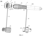
- the adapter 1 includes a lock nut 11, a connection lanyard 12, a ceramic sleeve 13, an adapter body 14, a sealing ring 15, and a protective cap 16.
- the adapter body 14 includes an input end 141 and an output end 142 that is away from the input end 141.
- a penetration hole 143 extending from the input end 141 to the output end 142 is disposed in the adapter body 14.
- An optical signal can be input from the input end 141 of the adapter body 14 and output from the output end 142 through the penetration hole 143.
- the penetration hole 143 accommodates a part of the connecting piece 31 of the optical fiber connector 3.
- a shape of the penetration hole 143 is adapted to a shape of the connecting piece 31 accommodated by the penetration hole 143.
- the ceramic sleeve 13 is disposed in each penetration hole 143. The ceramic sleeve 13 is configured to abut against a part of the connecting piece 31 of the optical fiber connector 3 to transmit an optical signal.
- a lock slot 1412 is disposed on an outer sidewall 1411 of the input end 141.
- the lock slot 1412 extends a second angle in a circumferential direction of the input end 141, and the second angle is less than or equal to 90°.
- the outer sidewall 1411 of the input end 141 is a cylindrical surface.
- the circumferential direction of the input end 141 is a direction perpendicular to and around a central axis of the outer sidewall 1411 of the input end 141.
- the second angle is a central angle of the lock slot 1412.
- the second angle may be an angle from 30° to 90°, such as 30°, 45°, 60°, 75°, or 90°.
- lock slots 1412 there may be one, two, three or more than three lock slots 1412.
- This embodiment is described by using an example in which there are two lock slots 1412.
- the two lock slots 1412 are disposed facing away from each other.
- the two lock slots 1412 are centrosymmetrically distributed.
- a quantity of the lock slots 1412 may be designed based on the second angle, provided that a plurality of lock slots 1412 are designed to be spaced apart from each other. For example, when the second angle is less than 60°, there may be three lock slots 1412.
- the adapter body 14 further includes a stop flange 144 located between the input end 141 and the output end 142.
- An alignment arrow mark 1441 is disposed on a side that is of the stop flange 144 and that faces the input end 141.
- the alignment arrow mark 1441 is configured to indicate a state of connection/disconnection between another component and the adapter body 14.
- a threaded connection portion 1422 is disposed on an outer sidewall 1421 of the output end 142.
- the lock nut 11 is screwed to the threaded connection portion 1422.
- the lock nut 11 is configured to be connected to a box body of a fiber termination box (refer to 101 or 301 in FIG. 1 ).
- the lock nut 11 may alternatively be a connection component configured to implement another connection manner, and the threaded connection portion 1422 is another structure corresponding to the connection component.
- the another connection manner includes but is not limited to a snap-fit connection, a mortise and tenon connection, an interference connection, or an elastic connection.
- FIG. 4 is a schematic diagram of a structure of the protective cap 16 shown in FIG. 3 .
- connection lanyard 12 is sleeved on an outer side of the adapter body 14, and the other end 122 of the connection lanyard 12 is connected to the protective cap 16.
- the end 121 of the connection lanyard 12 is sleeved on an outer side of the output end 142, and is located between the stop flange 144 and the lock nut 11.
- the protective cap 16 includes a connection cap portion 161 and a holding part 322. A top of the connection cap portion 161 is open.
- the holding part 162 is located on a bottom of the connection cap portion 161.
- a connection groove 163 is disposed between the connection cap portion 161 and the holding part 162.
- the connection groove 163 is a continuous annular groove.
- the end 122 that is of the connection lanyard 12 and that is away from the adapter body 14 is located in the connection groove 163, to connect the protective cap 16.
- a protective lock protrusion 164 is disposed on an inner side of an end of the protective cap 16.
- the end of the protective cap 16 can be sleeved on an outer sidewall of the input end 141, and the protective lock protrusion 164 is snap-fitted to the lock slot 1412.
- the protective lock protrusion 164 is disposed on an inner side of the connection cap portion 161.
- the protective lock protrusion 164 slides through the slide area 1414 to the snap-fit area 1415, and then is snap-fitted to the snap-fit surface 1416 of the snap-fit area 1415.
- a snap-fit matching surface matching the snap-fit surface 1416 may be further disposed on the protective lock protrusion 164, to improve snap-fit stability between the protective lock protrusion 164 and the adapter body 14.
- the protective cap 16 is connected to the adapter body 14 in a rotary snap-fit lock manner.
- a structure of the lock slot 1412 is designed, so that an angle of rotation of the protective cap 16 relative to the adapter body 14 is less than or equal to the second angle, where the second angle is less than or equal to 90°. Therefore, assembly and disassembly of the protective cap 16 are simple and time-saving, and a snap-fit connection between the protective cap 16 and the adapter body 14 is highly stable and secure. In this way, the protective cap 16 can effectively protect the adapter body 14 from water, dust, and the like, thereby helping improve reliability of the adapter 1.
- the protective cap 16 is connected to the adapter body 14 by using the connection lanyard 12, so that the protective cap 16 is difficult to be detached, thereby improving the reliability of the adapter 1.
- the connecting piece 31 is partially located in the inner through-hole 395 of the lock cap 39, and the connecting piece 31 partially protrudes relative to an end that is of the lock cap 39 and that is away from the tail ferrule 320.
- the optical cable 2 of the prefabricated optical fiber 20 can extend from one end that is of the tail ferrule 320 and that is away from the lock cap 39 sequentially into the inner through-hole of the tail ferrule 320 and the inner through-hole 395 of the lock cap 39, to be connected to the connecting piece 31.
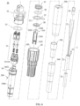
- Other structures of the optical fiber connector 3 are located in the inner through-hole 395 of the lock cap 39 and the inner through-hole of the tail ferrule 320.
- an inner surface of the protective housing 3121 includes a first locating surface 3125 facing the fastening portion 3111.
- the inner surface is a hole wall of the inner through-hole of the protective housing 3121.
- the first locating surface 3125 faces a bottom end face of the protective housing 3121.
- the ferrule 3122 is of a hollow cylinder structure.
- the ferrule 3122 has a bottom close to the fastening portion 3111 and a top away from the fastening portion 3111.
- An outer sidewall of the ferrule 3122 includes a second locating surface 3126 facing away from the fastening portion 3111.
- the second locating surface 3126 faces a top of the ferrule 3122.
- the outer sidewall of the ferrule 3122 further includes an abutting face 3127 facing the fastening portion 3111.
- the abutting face 3127 and the second locating surface 3126 are disposed facing away from each other.
- the elastic connection part 313 is compressed between the ferrule 3122 and the mounting portion 3112. An elastic force of the elastic connection part 313 firmly presses the second locating surface 3126 against the first locating surface 3125.
- one end of the elastic connection part 313 is located between the ferrule 3122 and a body of the protective housing 3121, and abuts against the abutting face 3127 of the ferrule 3122.
- the other end of the elastic connection part 313 is located in the mounting portion 3112 and abuts against the abutting face 31111 of the mounting portion 3112.
- the ferrule 3122 is fastened relative to the protective housing 3121, and the ferrule 3122 is not swaying. This helps ensure connection reliability between the optical fiber connector 3 and the adapter 1.
- the top end face 3128 of the protective housing 3121 can protect the ferrule 3122.
- one or more protective protrusions 31210 are disposed on a top of the protective housing 3121.
- An end face that is of the one or more protective protrusions 31210 and that is away from the connection base is the top end face 3128 of the protective housing 3121.
- two protective protrusions 31210 opposite to each other are further disposed on the top of the protective housing 3121.
- the two protective protrusions 31210 are located on two sides of the inner through-hole of the protective housing 3121 respectively.
- the two protective protrusions 31210 are respectively connected to the two sidewalls that are of the protective housing 3121 and that face away from each other.
- FIG. 12 is a sectional view along a line A-A of the prefabricated optical fiber 20 shown in Figure 5 .
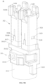
- the connecting piece 31 is fixedly connected to the head end 341 of the main shaft 34 and partially accommodated in the through hole 344.
- the optical cable 2 extends into the through hole 344 and is connected to the connecting piece 31.
- the term "fixedly connected" indicates that a relative location relationship between two assembled components is fixed, and a connection between the two components may be a detachable connection, or a non-detachable connection.
- one end of the connection base 311 of the connecting piece 31 is inserted into the through hole 344, and the one or more connection terminals 312 are fastened to the other end of the connection base 311.
- connection base 311 abuts against a top end face of the main shaft 34 (that is, a top end face that is of the head end 341 and that is away from the tail end 342).
- the connecting piece 31 and the main shaft 34 are located to each other in the axial direction of the optical fiber connector 31.
- the second locating hole 31114 of the fastening portion 3111 of the connecting piece 31 aligns with the first locating hole 3452 of the lug 345 of the main shaft 34.
- a bolt 350 may be inserted into the first locating hole 3452 and the second locating hole 31114, so that the connecting piece 31 and the main shaft 34 are located to each other in the axial direction and a circumferential direction (perpendicular to and around the axial direction of the optical fiber connector 31) of the optical fiber connector 31.
- the insertion block 3115 (refer to FIG. 9A and FIG. 9B ) on the connection base 311 of the connecting piece 31 is inserted into the insertion slot 3414 (refer to FIG. 7 ) on the head end 341 of the main shaft 34.
- the insertion block 3115 is fitted to the insertion slot 3414, so that the main shaft 34 and the connecting piece 31 are located to each other in the circumferential direction of the optical fiber connector 31.
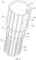
- FIG. 13 is a schematic diagram of a structure of the lock cap 39 shown in FIG. 6
- FIG. 14 is a schematic diagram of an internal structure of the lock cap 39 shown in FIG. 13 .
- the lock cap 39 is a hollow cylinder.
- the lock cap 39 is sleeved on the outer side of the main shaft 34 and the outer side of the connecting piece 31.
- the lock cap 39 includes a sealing portion 391 and a connection portion 392 that is connected to a side of the sealing portion 391.
- the lock cap 39 further includes a limiting portion 393 connected to a side that is of the sealing portion 391 and that is away from the connection portion 392.
- the connection portion 392, the sealing portion 391, and the limiting portion 393 are sequentially arranged in the axial direction of the optical fiber connector 3.
- the inner through-hole 395 of the lock cap 39 penetrates from an end of the connection portion 392 to an end of the limiting portion 393.
- the sealing portion 391 is rotationally connected to the outer side of the head end 341 of the main shaft 34.
- the connection portion 392 is located on a side that is of the head end 341 and that is away from the tail end 342.
- the connection portion 392 wraps around the connecting piece 31.
- the limiting portion 393 is located on an outer side of the transition section 343. Referring to FIG. 2 , when the optical fiber connector 3 is connected to the adapter 1, the connecting piece 31 is partially inserted into the input end 141 of the adapter body 14, and the input end 141 of the adapter body 14 is inserted into the connection portion 392 of the lock cap 39.
- the connection portion 392 is configured to partially accommodate the adapter 1 when the connecting piece 31 is inserted into the adapter 1.
- an inner diameter of the connection portion 392 is greater than an inner diameter of the sealing portion 391.
- the inner diameter of the sealing portion 391 is greater than an inner diameter of the limiting portion 393.
- the inner through-hole 395 of the lock cap 39 is a hole with varying diameters.
- the inner through-hole 395 of the lock cap 39 may alternatively be a through-hole in another shape.
- an outer diameter D1 of the sealing portion 391 is less than an outer diameter D2 of the connection portion 392.
- An outer diameter D3 of the limiting portion 393 may be further less than the outer diameter D1 of the sealing portion 391. That is, the outer diameter D2 of the connection portion 392, the outer diameter D1 of the sealing portion 391, and the outer diameter D3 of the limiting portion 393 sequentially decreases.
- An outer circumferential surface of the lock cap 39 has a step-shaped structure, to meet a requirement for accommodation capacity of the lock cap 39 (where the lock cap 39 is required to accommodate most components of the optical fiber connector 3), and minimize a volume of the lock cap 39. Therefore, the optical fiber connector 3 is more compact.
- a lock protrusion 394 is disposed on an inner side of the connection portion 392.
- the lock protrusion 394 is located on a hole wall of the inner through-hole 395 of the lock cap 39.
- the two lock protrusions 394 are disposed opposite to each other.
- the lock protrusion 394 is configured to be snap-fitted to the lock slot 1412 of the adapter 1 when the lock cap 39 is rotated by a first angle relative to the adapter 1.
- the first angle is less than or equal to 90°.
- the connecting piece 31 is partially inserted into the penetration hole 143 of the adapter body 14
- the connection portion 392 partially accommodates the input end 141 of the adapter body 14 and the lock protrusion 394 is located in the lock slot 1412.
- the lock protrusion 394 is snap-fitted to the lock slot 1412 when the lock cap 39 is rotated by the first angle relative to the adapter body 14.
- the first angle is less than or equal to the second angle.
- the lock protrusion 394 slides from the slide-in area 1413 to the lock slot 1412.
- the lock protrusion 394 slides through the slide area 1414 to the snap-fit area 1415, and then is snap-fitted to the snap-fit surface 1416 of the snap-fit area 1415.
- the penetration hole 143 of the adapter body 14 may be configured to accommodate a part of the connecting piece 31 of the optical fiber connector 3 when the input end 141 is inserted into the lock cap 39 of the optical fiber connector 3.
- the lock slot 1412 of the adapter body 14 is configured to accommodate the lock protrusion 394 on the inner side of the lock cap 39 and be snap-fitted to the lock protrusion 394.
- the first angle of rotation of the lock cap 39 relative to the adapter body 14 is limited by a structure of the lock slot 1412, and the lock slot 1412 extends the second angle in the circumferential direction of the input end 141 of the adapter body 14, so that the first angle is less than or equal to the second angle.
- the lock cap 39 is connected to the adapter body 14 in a rotary snap-fit lock manner. Therefore, the structure of the lock slot 1412 can be designed, to set or change a size of the first angle, thereby changing the angle of rotation required when the lock cap 39 is connected to the adapter body 14.
- the lock cap 39 is connected to the adapter body 14 in a rotary snap-fit lock manner, the angle of rotation of the lock cap 39 relative to the adapter body 14 is less than or equal to the second angle, and the second angle is less than or equal to 90°, so that the lock cap 39 only needs to be rotated by an angle less than one fourth of a circle relative to the adapter body 14, to complete assembly or disassembly of the optical fiber connector 3 and the adapter 1.
- assembly and disassembly of the optical fiber connection assembly 200 are simple and time-saving (approximately one fifth of a time required by a conventional optical fiber connection assembly, or even a shorter time), the snap-fit connection between the optical fiber connector 3 and the adapter 1 is highly stable and secure, and signal transmission of the optical fiber connection assembly 200 is highly reliable.
- no conventional elastic arm is disposed on the connection terminal 312 (refer to FIG. 9B ) of the optical fiber connector 3 in this embodiment.
- a lock requirement between the optical fiber connector 3 and the adapter 1 is met by using a rotary snap-fit lock structure, so that a conventional two-step assembly/disassembly process (elastic arm assembly/disassembly and protective cover assembly/disassembly) is simplified into a one-step assembly/disassembly process, thereby further reducing difficulty of and a time for assembly and disassembly of the optical fiber connector 3 and the adapter 1.
- no elastic arm structure is disposed on the connection terminal 312, so that a volume of the connection terminal 312 is reduced. Therefore, a port density can be increased without increasing a volume of the optical fiber connector 3.
- a snap-fit matching surface matching the snap-fit surface 1416 may be further disposed on the lock protrusion 394, to improve snap-fit stability between the lock protrusion 394 and the adapter body 14. It can be understood that a structure of the lock protrusion 394 matches the structure of the lock slot 1412, and a rotary snap-fit lock connection structure for the lock cap 39 and the adapter body 14 is the same as a rotary snap-fit lock connection structure for the protective cap 16 of the adapter 1 and the adapter body 14.
- Shallow grooves are disposed on both the outer sidewall 3921 of the connection portion 392 and an outer sidewall 3911 of the sealing portion 391.
- a shallow groove 3923 of the connection portion 392 and a shallow groove 3912 of the sealing portion 391 are connected and continuously extend in an axial direction of the lock cap 39 (that is, the axial direction of the optical fiber connector 3).
- the shallow groove 3923 of the connection portion 392 and the shallow groove 3912 of the sealing portion 391 may alternatively have another shape and another connection relationship.
- An outer sidewall of the limiting portion 393 includes a plurality of symmetrically arranged edge-cut planes 3931. There are four edge-cut planes 3931.
- edge-cut planes 3931 that are opposite to each other form one group of edge-cut planes 3931.
- a shallow groove 3932 is disposed on each edge-cut plane 3931.
- the shallow groove 3932 may extend in a direction perpendicular to the axial direction. This provides a user with better hand feel and the lock cap 39 is not likely to slide when the user holds or operates the lock cap 39.
- a stop plane 3913 facing the connection portion 392 is disposed on the sealing portion 391.
- the stop plane 3913 is a part of the hole wall of the inner through-hole 395 of the lock cap 39.
- a second limiting surface 3924 facing the sealing portion 391 is disposed on the limiting portion 393.
- the second limiting surface 3924 may be a part of an end face that is of the limiting portion 393 and that is connected to the sealing portion 391.
- the second limiting surface 3924 is a part of the hole wall of the inner through-hole 395 of the lock cap 39.
- the optical fiber connector 3 further includes the elastic part 35.
- the elastic part 35 is located between the transition section 343 and the sealing portion 391, and two ends of the elastic part 35 abut against the first limiting surface 3431 and the second limiting surface 3924 respectively.
- the elastic part 35 is disposed, so that the first limiting surface 3431 and the second limiting surface 3924 tend to move away from each other, and the lock cap 39 tends to move toward the tail end 342 of the main shaft 34. Therefore, when the lock cap 39 is connected to the adapter 1 (refer to FIG. 3 ), the lock protrusion 394 can be stably snap-fitted to the lock slot 1412 of the adapter body 14, and the connecting piece 31 and the adapter body 14 are fastened to each other in the axial direction of the optical fiber connector 3, so that a connection relationship between the lock cap 39 and the adapter 1 is reliable, thereby achieving good shockproof and anti-looseness effects.
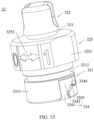
- FIG. 15 is a schematic diagram of a structure of the dust cap 32 shown in FIG. 6 .
- one end 371 of the lanyard 37 of the optical fiber connector 3 is sleeved on the outer side of the main shaft 34, and the other end 372 of the lanyard 37 is connected to the dust cap 32.
- the dust cap 32 includes an insertion portion 321 and a holding portion 322. A top side of the insertion portion 321 is open. The holding portion 322 is connected to a bottom side of the insertion portion 321. A connection groove 323 is disposed between the insertion portion 321 and the holding portion 322. The connection groove 323 is a continuous annular groove.
- the end 372 that is of the lanyard 37 and that is away from the main shaft 34 is located in the connection groove 323, to connect the dust cap 32.
- a dustproof lock slot 324 is disposed on an end of the dust cap 32.
- the end of the dust cap 32 can extend into the connection portion 392, and the dustproof lock slot 324 is snap-fitted to the lock protrusion 394.
- the dustproof lock slot 324 is disposed on an outer sidewall 3211 of the insertion portion 321.
- the dustproof lock slot 324 extends a third angle in a circumferential direction of the insertion portion 321. The third angle may be less than or equal to 90°.
- the outer sidewall 3211 of the insertion portion 321 is a cylindrical surface.
- the circumferential direction of the insertion portion 321 is a direction perpendicular to and around a central axis of the outer sidewall 3211 of the insertion portion 321.
- the third angle is a central angle of the dustproof lock slot 324.
- the third angle may be an angle from 30° to 90°, such as 30°, 45°, 60°, 75°, or 90°.
- the dustproof lock slot 324 includes a slide-in area 3241, a slide area 3242, and a snap-fit area 3242 that are sequentially connected.
- the slide area 3242 and the snap-fit area 3243 extend in the circumferential direction of the insertion portion 321.
- the slide-in area 3241 connects the slide area 3242 to an end face of the insertion portion 321.
- a snap-fit surface 3244 facing away from the slide-in area 3242 is disposed on the snap-fit area 3243.
- a direction from the slide area 3242 to the snap-fit area 3243 is a slide-in direction
- an orientation of the snap-fit surface 3244 is opposite to the slide-in direction.
- the insertion portion 321 of the dust cap 32 completely or partially extends into the connection portion 392 of the lock cap 39.
- the connecting piece 31 partially extends into the insertion portion 321.
- the lock protrusion 394 of the lock cap 39 slides from the slide-in area 3241 to the dustproof lock slot 324.
- the lock protrusion 394 slides through the slide area 3242 to the snap-fit area 3243, and then is snap-fitted to the snap-fit surface 3244 of the snap-fit area 3243.
- a snap-fit matching surface matching the snap-fit surface 3244 may be further disposed on the lock protrusion 394 of the lock cap 39, to improve snap-fit stability between the lock protrusion 394 and the dust cap 32.
- the lock cap 39 of the optical fiber connector 3 of the optical fiber connection assembly 200 is connected to the adapter body 14 of the adapter 1 by using a rotary snap-fit lock structure
- the lock cap 39 of the optical fiber connector 3 is connected to the dust cap 32 of the optical fiber connector 3 also by using a rotary snap-fit lock structure
- the protective cap 16 of the adapter 1 is connected to the adapter body 14 also by using a rotary snap-fit lock structure. Therefore, a connection structure of the protective cap 16 of the adapter 1 is similar to a connection structure of the lock cap 39 of the optical fiber connector 3, and a connection structure of the dust cap 32 of the optical fiber connector 3 is similar to a connection structure of the adapter body 14 of the adapter 1.
- a connection between the optical fiber connector 3 and the adapter 1, a connection between components of the optical fiber connector 3, and a connection between components of the adapter 1 are implemented by using same rotary snap-fit lock structures, so that a structure of the optical fiber connection assembly 200 is further simplified and installation is less difficult.
- the third angle is equal to the second angle, so that the connection action between the dust cap 32 and the lock cap 39 is the same as the connection action between the adapter body 14 and the lock cap 39, thereby improving user experience.
- dustproof lock slots 324 there may be one, two, or more than three dustproof lock slots 324.
- This embodiment is described by using an example in which there are two dustproof lock slots 324.
- the two dustproof lock slots 324 are disposed facing away from each other.
- the two dustproof lock slots 324 are centrosymmetrically distributed.
- a quantity of the dustproof lock slots 324 may be designed based on the second angle, provided that a plurality of dustproof lock slots 324 are designed to be spaced apart from each other. For example, when the second angle is less than 60°, there may be three dustproof lock slots 324.
- the dust cap 32 further includes a middle portion 325 located between the insertion portion 321 and the holding portion 322.
- An alignment arrow mark 3252 is disposed on an outer sidewall 3251 of the middle portion 325.
- the alignment arrow mark 3252 is configured to indicate a connection/disconnection state of another component and the dust cap 32.
- the first sealing ring 33 of the optical fiber connector 3 is located in the connection portion 392.
- a sealing connection groove 3212 is disposed on the outer sidewall 3211 of the insertion portion 321 of the dust cap 32.
- the sealing connection groove 3212 is located between the middle portion 325 and the dustproof lock slot 324.
- the first sealing ring 33 is mounted in the sealing connection groove 3212.
- the first sealing ring 33 is configured to be compressed between the connection portion 392 and the adapter 1.
- the sealing ring 15 of the adapter 1 is detached from the sealing groove 1418.
- the first sealing ring 33 is mounted in the sealing groove 1418.
- the first sealing ring 33 is configured to seal a connection between the lock cap 39 and another component, to achieve waterproof and dustproof effects, so that the optical fiber connector 3 can achieve a protection level of IP68 and has a longer service life and higher reliability.
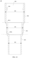
- FIG. 16 is a schematic diagram of an internal structure of the sealing sleeve 340 shown in FIG. 6 .
- One end 3401 of the sealing sleeve 340 of the optical fiber connector 3 is sleeved on an outer side of the tail end 342 of the main shaft 34 in a sealing manner.
- the other end 3402 of the sealing sleeve 340 is configured to allow insertion of the optical cable 2 and be connected to the optical cable 2 in a sealing manner.
- the sealing sleeve 340 is a hollow cylinder.
- the optical cable 2 is inserted into and passes through an inner through-hole of the sealing sleeve 340, and then enters the through hole 344 of the main shaft 34.
- the sealing sleeve 340 is configured to implement a sealed connection between the optical cable 2 and the main shaft 34, to improve reliability of the optical fiber connector 3 and extend a service life of the optical fiber connector 3.
- the sealing sleeve 340 may be a heat shrink tubing.
- the sealing sleeve 340 may be a tube with adhesive on an inner surface, to improve reliability of connections to both the tail end 342 of the main shaft 34 and the optical cable 2.
- an inner diameter of the end 3401 (a top end in FIG. 16 ) connected to the tail end 342 of the main shaft 34 is greater than an inner diameter of the end 3402 (a bottom end in FIG. 16 ) connected to the optical cable 2.
- An inner diameter of a middle portion 3403 between the two ends (3401/3402) of the sealing sleeve 340 may be between the inner diameters of the two ends (3401/3402).
- An inner through-hole 3404 of the sealing sleeve 340 may be a hole with varying diameters.
- An outer sidewall of the sealing sleeve 340 is substantially step-shaped.
- the sealing sleeve 340 is connected to a part of the metal portion 3422 and a part of the rubber portion 3421 in a sealing manner.
- the end 3401 connected to the tail end 342 of the main shaft 34 is connected to both a part of the metal portion 3422 and a part of the rubber portion 3421 in a sealing manner.
- a connection relationship between the sealing sleeve 340 and the tail end 342 of the main shaft 34 is more stable and reliable.
- FIG. 17 is a schematic diagram of an internal structure of the metal crimp ring 330 shown in FIG. 6 .
- the metal crimp ring 330 firmly presses the aramid yarn 22 against the metal portion 3422, thereby improving connection strength between the optical cable 2 and the main shaft 34, and improving tensile strength of the optical fiber connector 3.
- the optical fiber connector 3 further includes the snap ring 38.
- the snap ring 38 is mounted in the limiting groove 3423 of the tail end 342 of the main shaft 34 (refer to FIG. 7 ).
- the snap ring 38 is fastened relative to the main shaft 34.
- An outer sidewall of the snap ring 38 forms a step-shaped structure.
- the outer sidewall of the snap ring 38 has a step-shaped surface 381.
- the step-shaped surface 381 faces the transition section 343 of the main shaft 34.
- the inner snap-fit flange 3202 of the tail ferrule 320 abuts against the step-shaped surface 381.
Landscapes
- Physics & Mathematics (AREA)
- General Physics & Mathematics (AREA)
- Optics & Photonics (AREA)
- Mechanical Coupling Of Light Guides (AREA)
- Light Guides In General And Applications Therefor (AREA)
Claims (14)
- Faseroptischer Verbinder (3), umfassend einen Hauptschaft (34), ein Verbindungsstück (31) und eine Verschlusskappe (39), wobei der Hauptschaft (34) ein Kopfende (341) und ein Schwanzende (342) umfasst, das von dem Kopfende (341) weg weist, ein Durchgangsloch (344), das sich von dem Kopfende (341) zu dem Schwanzende (342) erstreckt, in dem Hauptschaft (34) angeordnet ist, das Verbindungsstück (31) fest mit dem Kopfende (341) verbunden ist und teilweise in dem Durchgangsloch (344) aufgenommen ist, die Verschlusskappe (39) einen Dichtungsabschnitt (391) und einen Verbindungsabschnitt (392) umfasst, der mit einer Seite des Dichtungsabschnitts (391) verbunden ist, der Dichtungsabschnitt (391) drehbar mit einer Außenseite des Kopfendes (341) verbunden ist, sich der Verbindungsabschnitt (392) auf einer Seite befindet, die von dem Kopfende (341) ist und die von dem Schwanzende (342) weg weist, der Verbindungsabschnitt (392) dazu konfiguriert ist, einen Adapter (1) teilweise aufzunehmen, wenn das Verbindungsstück (31) in den Adapter (1) eingeführt ist, ein Sperrvorsprung (394) an einer Innenseite des Verbindungsabschnitts (392) angeordnet ist und der Sperrvorsprung (394) dazu konfiguriert ist, in einem Sicherheits-Slot (39) des Adapters (1) einzurasten, wenn die Verschlusskappe (39) um einen ersten Winkel relativ zu dem Adapter (1) gedreht wird, wobei der erste Winkel kleiner oder gleich 90° ist;
dadurch gekennzeichnet, dassdas Verbindungsstück (31) eine Verbindungsbasis (311) und einen oder mehrere Verbindungsanschlüsse (312) umfasst, wobei ein Ende der Verbindungsbasis (311) in das Durchgangsloch (344) eingeführt ist und der eine oder die mehreren Verbindungsanschlüsse (312) an dem anderen Ende der Verbindungsbasis 311 befestigt sind;wobei die Verbindungsbasis (311) einen Befestigungsabschnitt (3111) und einen oder mehrere Montageabschnitte (3112) umfasst, die sich auf einer Seite des Befestigungsabschnitts (3111) befinden, wobei der eine oder die mehreren Montageabschnitte (3112) teilweise in einer Eins-zu-eins-Entsprechung in den einen oder die mehreren Verbindungsanschlüsse (312) eingeführt sind und der Befestigungsabschnitt (3111) und der eine oder die mehreren Montageabschnitte (3112) einstückig ausgebildet sind;wobei zwei Anschlussklemmen (345) auf einer Oberseite des Kopfendes (341) angeordnet sind, zwei Begrenzungsblöcke (3451) der zwei Anschlussklemmen (345) zueinander gebogen sind und wobei die zwei Anschlussklemmen (345) einander gegenüberliegend angeordnet sind; undwobei eine Positionierebene (31112), die dem einen oder den mehreren Montageabschnitten (3112) zugewandt ist, an dem Befestigungsabschnitt (3111) angeordnet ist, wobei, wenn die Verbindungsbasis (311) des Verbindungsstücks (31) an dem Hauptschaft (34) montiert ist, die zwei Begrenzungsblöcke (3451) an den zwei Anschlussklemmen (345) des Kopfendes (341) des Hauptschafts (34) mit der Positionierebene (31112) eingerastet sind. - Faseroptischer Verbinder (3) nach Anspruch 1, wobei der Hauptschaft (34) ferner einen Übergangsbereich (343) umfasst, der sich zwischen dem Kopfende (341) und dem Schwanzende (342) befindet, eine erste Begrenzungsfläche (3431), die dem Schwanzende (342) zugewandt ist, auf dem Übergangsbereich (343) angeordnet ist, die Verschlusskappe (39) ferner einen Begrenzungsabschnitt (393) umfasst, der mit einer Seite des Dichtungsabschnitts (391) verbunden ist und der von dem Verbindungsabschnitt (392) weg weist, eine zweite Begrenzungsfläche (3924), die dem Dichtungsabschnitt (391) zugewandt ist, auf dem Begrenzungsabschnitt (393) angeordnet ist, der faseroptische Verbinder (3) ferner einen elastischen Teil (35) umfasst, sich der elastische Teil (35) zwischen dem Übergangsbereich (343) und dem Dichtungsabschnitt (391) befindet und zwei Enden des elastischen Teils (35) an der ersten Begrenzungsfläche (3431) bzw. der zweiten Begrenzungsfläche (3924) anliegen.
- Faseroptischer Verbinder (3) nach Anspruch 1, wobei der Verbindungsanschluss (312) ein Schutzgehäuse (3121) und eine in dem Schutzgehäuse (3121) montierte Ferrule (3122) und eine obere Endfläche umfasst, die von dem Schutzgehäuse (3121) ist und die von der Verbindungsbasis (311) weg weist, relativ zu einer oberen Endfläche vorsteht, die von der Ferrule (3122) ist und von der Verbindungsbasis (311) weg weist.
- Faseroptischer Verbinder (3) nach Anspruch 1, wobei der Verbindungsanschluss (312) ein Schutzgehäuse (3121) und eine in dem Schutzgehäuse (3121) montierte Ferrule (3122) umfasst, ein Begrenzungsloch (3123) an dem Schutzgehäuse (3121) angeordnet ist, ein Begrenzungsvorsprung (3119) an dem Montageabschnitt (3112) angeordnet ist, der Montageabschnitt (3112) teilweise in das entsprechende Schutzgehäuse (3121) eingeführt ist und der Begrenzungsvorsprung (3119) teilweise oder vollständig in dem Begrenzungsloch 3123 festgeklemmt ist.
- Faseroptischer Verbinder (3) nach Anspruch 4, wobei eine Innenfläche des Schutzgehäuses (3121) eine erste Positionierfläche (3125) umfasst, die dem Befestigungsabschnitt (3111) zugewandt ist, eine äußere Seitenwand der Ferrule (3122) eine zweite Positionierfläche (3126) aufweist, die von dem Befestigungsabschnitt (3111) weg weist, das Verbindungsstück (31) ferner einen elastischen Verbindungsteil (313) aufweist, der elastische Verbindungsteil (313) zwischen der Ferrule (3122) und dem Montageabschnitt (3112) verdichtet ist und eine elastische Kraft des elastischen Verbindungsteils (313) die zweite Positionierfläche (3126) fest gegen die erste Positionierfläche (3125) drückt.
- Faseroptischer Verbinder (3) nach einem der Ansprüche 1 bis 5, wobei ein Außendurchmesser des Dichtungsabschnitts (391) kleiner als ein Außendurchmesser des Verbindungsabschnitts 392 ist.
- Faseroptischer Verbinder (3) nach einem der Ansprüche 1 bis 6, wobei der faseroptische Verbinder (3) ferner einen ersten Dichtungsring 33 umfasst, sich der erste Dichtungsring 33 in dem Verbindungsabschnitt (392) befindet und der erste Dichtungsring 33 dazu konfiguriert ist, zwischen dem Verbindungsabschnitt (392) und dem Adapter 1 verdichtet zu werden.
- Faseroptischer Verbinder (3) nach einem der Ansprüche 1 bis 7, wobei eine Dichtungsnut 346, die das Durchgangsloch (344) umschließt, an einer äußeren Umfangsseite des Hauptschafts (34) angeordnet ist, der faseroptische Verbinder (3) ferner einen zweiten Dichtungsring 36 umfasst und der zweite Dichtungsring 36 zwischen einer Nutwand der Dichtungsnut 346 und einer Innenseitenfläche des Dichtungsabschnitts 391 verdichtet ist.
- Faseroptischer Verbinder (3) nach einem der Ansprüche 1 bis 8, wobei der faseroptische Verbinder (3) ferner eine Dichtungshülse (340) umfasst, wobei ein Ende der Dichtungshülse (340) dichtend auf eine Außenseite des Schwanzendes (342) aufgesteckt ist und das andere Ende der Dichtungshülse (340) dazu konfiguriert ist, ein Einführen eines optischen Kabels (2) zu ermöglichen und dichtend mit dem optischen Kabel (2) verbunden zu werden.
- Faseroptischer Verbinder (3) nach Anspruch 9, wobei das Schwanzende (342) einen Gummiabschnitt (3421) nahe dem Kopfende (341) und einen Metallabschnitt (3422), der von dem Kopfende weg weist, umfasst, sich der Metallabschnitt (3422) teilweise in dem Gummiabschnitt (3421) befindet und fest mit dem Gummiabschnitt (3421) verbunden ist, und die Dichtungshülse (340) dichtend mit einem Teil des Metallabschnitts (3422) und einem Teil des Gummiabschnitts (3421) verbunden ist.
- Faseroptischer Verbinder (3) nach Anspruch 10, wobei der faseroptische Verbinder (3) ferner einen Metall-Crimpring (330) umfasst, sich der Metall-Crimpring (330) in der Dichtungshülse (340) befindet, ein Ende des Metall-Crimprings (330) auf eine Außenseite des Metallabschnitts (3422) aufgesteckt ist, das andere Ende des Metall-Crimprings (330) dazu konfiguriert ist, auf eine Außenseite des optischen Kabels (2) aufgesteckt zu werden, und das Ende des Metall-Crimprings (330) in der Lage ist, ein Aramidgarn 22 des optischen Kabels (2) fest gegen den Metallabschnitt (3422) zu drücken.
- Faseroptischer Verbinder (3) nach einem der Ansprüche 1 bis 11, wobei der faseroptische Verbinder (3) ferner eine Staubkappe 32 und eine Schnur 37 umfasst, ein Ende der Schnur 37 auf eine Außenseite des Hauptschafts (34) aufgesteckt ist, das andere Ende der Schnur 37 mit der Staubkappe (39) verbunden ist, ein staubdichter Sicherheits-Slot (324) an einem Ende der Staubkappe (39) angeordnet ist, das Ende der Staubkappe (39) dazu in der Lage ist, sich in den Verbindungsabschnitt (392) zu erstrecken, und der staubdichte Sicherheits-Slot (324) an dem Sperrvorsprung (394) eingerastet ist.
- Faseroptische Verbindungsbaugruppe 200, die einen faseroptischen Verbinder (3) nach einem der Ansprüche 1 bis 11 und einen Adapter 1 umfasst, wobeiein Körper des Adapters 14 ein Eingangsende 141 und ein Ausgangsende 142, das von dem Eingangsende 141 weg weist, umfasst, ein Durchgangsloch 143, das sich von dem Eingangsende 141 zu dem Ausgangsende 142 erstreckt, in dem Adapterkörper 14 angeordnet ist, ein Sicherheits-Slot (1412) an einer äußeren Seitenwand des Eingangsendes 141 angeordnet ist, sich der Sicherheits-Slot (1412) in einer Umfangsrichtung des Eingangsendes 141 um einen zweiten Winkel erstreckt und der zweite Winkel kleiner oder gleich 90° ist;wenn das Verbindungsstück (31) teilweise in das Durchgangsloch 143 eingeführt ist, der Verbindungsabschnitt (392) einen Teil des Eingangsendes 141 aufnimmt und sich der Sperrvorsprung (394) in dem Sicherheits-Slot (1412) befindet, der Sperrvorsprung (394) in dem Sicherheits-Slot (1412) eingerastet wird, wenn die Verschlusskappe (39) um einen ersten Winkel relativ zu dem Adapterkörper 14 gedreht wird, und der erste Winkel kleiner oder gleich dem zweiten Winkel ist.
- Faseroptische Verbindungsbaugruppe nach Anspruch 13, wobei der Hauptschaft (34) ferner einen Übergangsbereich (343) umfasst, der sich zwischen dem Kopfende (341) und dem Schwanzende (342) befindet, eine erste Begrenzungsfläche (3431), die dem Schwanzende (342) zugewandt ist, auf dem Übergangsbereich (343) angeordnet ist, die Verschlusskappe (39) ferner einen Begrenzungsabschnitt (393) umfasst, der mit einer Seite verbunden ist, die von dem Dichtungsabschnitt (391) ist und die von dem Verbindungsabschnitt (392) weg weist, eine zweite Begrenzungsfläche (3924), die dem Dichtungsabschnitt (391) zugewandt ist, auf dem Begrenzungsabschnitt (393) angeordnet ist, der faseroptische Verbinder (3) ferner einen elastischen Teil (35) umfasst, sich der elastische Teil (35) zwischen dem Übergangsbereich (343) und dem Dichtungsabschnitt (391) befindet und zwei Enden des elastischen Teils (35) an der ersten Begrenzungsfläche (3431) bzw. der zweiten Begrenzungsfläche (3924) anliegen.
Applications Claiming Priority (1)
| Application Number | Priority Date | Filing Date | Title |
|---|---|---|---|
| PCT/CN2018/125659 WO2020133423A1 (zh) | 2018-12-29 | 2018-12-29 | 光纤连接头、预制光纤、适配器、光纤盒及光纤连接组件 |
Publications (3)
| Publication Number | Publication Date |
|---|---|
| EP3693773A1 EP3693773A1 (de) | 2020-08-12 |
| EP3693773A4 EP3693773A4 (de) | 2021-04-07 |
| EP3693773B1 true EP3693773B1 (de) | 2025-06-25 |
Family
ID=71126157
Family Applications (1)
| Application Number | Title | Priority Date | Filing Date |
|---|---|---|---|
| EP18927228.9A Active EP3693773B1 (de) | 2018-12-29 | 2018-12-29 | Faseroptischer verbinder und faseroptische verbindungsanordnung |
Country Status (9)
| Country | Link |
|---|---|
| US (1) | US11327246B2 (de) |
| EP (1) | EP3693773B1 (de) |
| JP (1) | JP7011049B2 (de) |
| CN (1) | CN111656237B (de) |
| BR (1) | BR112020003318B1 (de) |
| ES (1) | ES3038425T3 (de) |
| MX (1) | MX2020003161A (de) |
| MY (1) | MY207020A (de) |
| WO (1) | WO2020133423A1 (de) |
Families Citing this family (6)
| Publication number | Priority date | Publication date | Assignee | Title |
|---|---|---|---|---|
| WO2022216861A1 (en) | 2021-04-08 | 2022-10-13 | Commscope Technologies Llc | Telecommunications connector with latch release mechanism |
| CN113352007A (zh) * | 2021-07-22 | 2021-09-07 | 岗春激光科技(江苏)有限公司 | 一种激光切割用激光器安装辅助设备 |
| CN113727565B (zh) * | 2021-08-31 | 2022-12-09 | 青岛海信移动通信技术股份有限公司 | 密封连接结构以及智能终端设备 |
| CN114114566B (zh) * | 2021-10-09 | 2023-01-06 | 华为技术有限公司 | 连接盒 |
| CN114460695B (zh) * | 2022-01-25 | 2023-03-03 | 华为技术有限公司 | 光纤连接器及光纤连接器组件 |
| CN115437075B (zh) * | 2022-09-01 | 2023-07-25 | 烽火通信科技股份有限公司 | 一种光纤连接盒和光纤连接盒组件 |
Family Cites Families (26)
| Publication number | Priority date | Publication date | Assignee | Title |
|---|---|---|---|---|
| JPS5891711A (ja) | 1981-11-26 | 1983-05-31 | Kanegafuchi Chem Ind Co Ltd | アクリロニトリル系重合体、その製造方法及びそれからなるモダクリル系合成繊維 |
| JPS5891711U (ja) * | 1981-12-15 | 1983-06-21 | 日立電線株式会社 | 光フアイバ−心線接続部 |
| JPH01312517A (ja) * | 1988-06-13 | 1989-12-18 | Nippon Steel Weld Prod & Eng Co Ltd | 光ファイバ接続部 |
| JPH0451208A (ja) * | 1990-06-20 | 1992-02-19 | Nec Corp | 光コネクタ |
| TW213987B (de) * | 1991-12-19 | 1993-10-01 | American Telephone & Telegraph | |
| IT1277474B1 (it) * | 1995-08-10 | 1997-11-10 | Sirti Spa | Connettore multifibra con ferula cilindrica |
| JP2006146084A (ja) | 2004-11-24 | 2006-06-08 | Sumitomo Electric Ind Ltd | 光ファイバのフェルール取付構造および取付方法 |
| US7556437B2 (en) * | 2007-03-13 | 2009-07-07 | Adc Telecommunications, Inc. | Fiber optic connector with protective cap |
| KR20120030375A (ko) * | 2009-04-23 | 2012-03-28 | 쓰리엠 이노베이티브 프로퍼티즈 컴파니 | 현장 종단접속 가능한 광 커넥터를 위한 칼라 본체 |
| CN101988976B (zh) | 2009-08-05 | 2012-10-03 | 华为技术有限公司 | 微型双芯光纤连接器 |
| CN201689192U (zh) * | 2010-04-26 | 2010-12-29 | 连展科技(天津)有限公司 | 光纤连接器 |
| US8672560B2 (en) | 2010-08-06 | 2014-03-18 | Tyco Electronics Corporation | Hermaphroditic optical fiber ferrule |
| JP5000778B2 (ja) | 2010-09-06 | 2012-08-15 | 株式会社精工技研 | 光コネクタプラグ |
| CN202472043U (zh) * | 2011-12-23 | 2012-10-03 | 宁波展通电信设备实业有限公司 | 压卡式新型现场组装型光纤连接器及其光纤对接结构 |
| HUE031727T2 (en) * | 2012-06-26 | 2017-07-28 | Huawei Tech Co Ltd | Optical fiber connector, optical fiber adaptor and optical fiber connector assembly |
| TWM445188U (zh) * | 2012-08-10 | 2013-01-11 | Gloriole Electroptic Technology Corp | 光纖連接裝置 |
| TWM480682U (zh) * | 2014-01-24 | 2014-06-21 | Gloriole Electroptic Technology Corp | 適用於光纖連接器的作動裝置 |
| FR3021415A1 (fr) | 2014-05-21 | 2015-11-27 | Radiall Sa | Ferule de dimensions reduites pour contact optique, connecteur multi-contacts integrant une pluralite de telles ferules. |
| US9755382B2 (en) | 2015-03-13 | 2017-09-05 | Senko Advanced Components, Inc. | Connector system with interchangeable connector modules for optical fibers, electrical conductors, or both |
| GB2538089B (en) | 2015-05-06 | 2019-06-19 | Fibrefab Ltd | Fibre optic cable assembly |
| CN111948758A (zh) * | 2016-01-28 | 2020-11-17 | 扇港元器件股份有限公司 | 光纤混合适配器和连接器组件 |
| US9625658B1 (en) * | 2016-04-12 | 2017-04-18 | Jyh Eng Technology Co., Ltd. | Communication connector with alterable polarity |
| JP6337048B2 (ja) | 2016-07-21 | 2018-06-06 | ▲ホア▼▲ウェイ▼技術有限公司Huawei Technologies Co.,Ltd. | 光ファイバージョイント、光ファイバーアダプタ、および光ファイバーコネクタ |
| KR20210099211A (ko) | 2016-09-30 | 2021-08-11 | 후아웨이 테크놀러지 컴퍼니 리미티드 | 광섬유 부분 조립체, 광섬유 어댑터, 및 광섬유 연결기 |
| US20190391343A1 (en) | 2017-01-31 | 2019-12-26 | Sei Optifrontier Co., Ltd. | Optical connector and optical fiber with connector |
| CN108459378B (zh) * | 2018-02-22 | 2024-02-13 | 宁波市金泽通信设备有限公司 | 一种光纤连接器 |
-
2018
- 2018-12-29 CN CN201880037165.2A patent/CN111656237B/zh active Active
- 2018-12-29 JP JP2020512464A patent/JP7011049B2/ja active Active
- 2018-12-29 MY MYPI2020000647A patent/MY207020A/en unknown
- 2018-12-29 WO PCT/CN2018/125659 patent/WO2020133423A1/zh not_active Ceased
- 2018-12-29 MX MX2020003161A patent/MX2020003161A/es unknown
- 2018-12-29 EP EP18927228.9A patent/EP3693773B1/de active Active
- 2018-12-29 BR BR112020003318-9A patent/BR112020003318B1/pt active IP Right Grant
- 2018-12-29 ES ES18927228T patent/ES3038425T3/es active Active
-
2020
- 2020-03-16 US US16/819,913 patent/US11327246B2/en active Active
Also Published As
| Publication number | Publication date |
|---|---|
| CN111656237B (zh) | 2022-06-14 |
| EP3693773A4 (de) | 2021-04-07 |
| MY207020A (en) | 2025-01-24 |
| MX2020003161A (es) | 2020-07-29 |
| US20200218014A1 (en) | 2020-07-09 |
| JP2021512345A (ja) | 2021-05-13 |
| CN111656237A (zh) | 2020-09-11 |
| US11327246B2 (en) | 2022-05-10 |
| BR112020003318B1 (pt) | 2024-02-20 |
| JP7011049B2 (ja) | 2022-01-26 |
| WO2020133423A1 (zh) | 2020-07-02 |
| BR112020003318A2 (pt) | 2021-07-20 |
| ES3038425T3 (en) | 2025-10-13 |
| EP3693773A1 (de) | 2020-08-12 |
Similar Documents
| Publication | Publication Date | Title |
|---|---|---|
| US11327246B2 (en) | Optical fiber connector, prefabricated optical fiber, adapter, fiber termination box, and optical fiber connection assembly | |
| JP3240929U (ja) | 光ファイバサブアセンブリ及び光ファイバコネクタ | |
| EP3514590B1 (de) | Glasfaserunteranordnung und glasfaserstecker | |
| EP2759860B1 (de) | Dichtungsgehäuse für einen Verbinder an einem Kabel wie z. B. standardisierte Glasfaserverbinder | |
| US11579374B2 (en) | Hybrid ingress protected connector and adapter assembly | |
| US8061906B2 (en) | Fibre optic duplex connector | |
| KR20020006481A (ko) | 이중 기능의 먼지 덮개 | |
| US9507102B2 (en) | Connector assemblies and methods for providing sealing and strain-relief | |
| TW201518799A (zh) | 光纖連接頭、光纖適配器及光纖連接器 | |
| US8834037B2 (en) | Hermaphroditic connector with multi-fiber termini | |
| US12259583B2 (en) | Pre-connector and communications device | |
| EP3021145B1 (de) | Optischer Adapter zur Montage an einem Behälter zum optischen Verbinden anschlussfertiger optischer Kabel | |
| WO2019157660A1 (zh) | 光纤连接头、光纤适配器和光纤连接装置 | |
| CN112394454A (zh) | 一种线缆保护壳及通信设备 | |
| US10473868B2 (en) | Optical connector plug having a removable and replaceable mating interface | |
| RU2782170C1 (ru) | Оптоволоконный коннектор, пред-изготовленное оптическое волокно, адаптер, блок терминации волокна и узел оптоволоконного соединения | |
| EP2993502B1 (de) | Optischer Adapter zur Montage an einen Behälter zum optischen Verbinden anschlussfertiger optischer Kabel | |
| TWM629465U (zh) | Emi屏蔽件以及具有emi屏蔽件的光纖轉接模組 | |
| CN119960122A (zh) | 一种光纤适配器及分纤箱体 |
Legal Events
| Date | Code | Title | Description |
|---|---|---|---|
| STAA | Information on the status of an ep patent application or granted ep patent |
Free format text: STATUS: UNKNOWN |
|
| STAA | Information on the status of an ep patent application or granted ep patent |
Free format text: STATUS: THE INTERNATIONAL PUBLICATION HAS BEEN MADE |
|
| PUAI | Public reference made under article 153(3) epc to a published international application that has entered the european phase |
Free format text: ORIGINAL CODE: 0009012 |
|
| STAA | Information on the status of an ep patent application or granted ep patent |
Free format text: STATUS: REQUEST FOR EXAMINATION WAS MADE |
|
| 17P | Request for examination filed |
Effective date: 20200128 |
|
| AK | Designated contracting states |
Kind code of ref document: A1 Designated state(s): AL AT BE BG CH CY CZ DE DK EE ES FI FR GB GR HR HU IE IS IT LI LT LU LV MC MK MT NL NO PL PT RO RS SE SI SK SM TR |
|
| AX | Request for extension of the european patent |
Extension state: BA ME |
|
| RIN1 | Information on inventor provided before grant (corrected) |
Inventor name: XIONG, RUI Inventor name: QI, BIAO Inventor name: LI, XIUPENG |
|
| RIC1 | Information provided on ipc code assigned before grant |
Ipc: G02B 6/38 20060101AFI20201001BHEP |
|
| A4 | Supplementary search report drawn up and despatched |
Effective date: 20210305 |
|
| RIC1 | Information provided on ipc code assigned before grant |
Ipc: G02B 6/38 20060101AFI20210301BHEP |
|
| DAV | Request for validation of the european patent (deleted) | ||
| DAX | Request for extension of the european patent (deleted) | ||
| STAA | Information on the status of an ep patent application or granted ep patent |
Free format text: STATUS: EXAMINATION IS IN PROGRESS |
|
| 17Q | First examination report despatched |
Effective date: 20221006 |
|
| GRAP | Despatch of communication of intention to grant a patent |
Free format text: ORIGINAL CODE: EPIDOSNIGR1 |
|
| STAA | Information on the status of an ep patent application or granted ep patent |
Free format text: STATUS: GRANT OF PATENT IS INTENDED |
|
| INTG | Intention to grant announced |
Effective date: 20241126 |
|
| GRAJ | Information related to disapproval of communication of intention to grant by the applicant or resumption of examination proceedings by the epo deleted |
Free format text: ORIGINAL CODE: EPIDOSDIGR1 |
|
| STAA | Information on the status of an ep patent application or granted ep patent |
Free format text: STATUS: EXAMINATION IS IN PROGRESS |
|
| GRAP | Despatch of communication of intention to grant a patent |
Free format text: ORIGINAL CODE: EPIDOSNIGR1 |
|
| STAA | Information on the status of an ep patent application or granted ep patent |
Free format text: STATUS: GRANT OF PATENT IS INTENDED |
|
| INTC | Intention to grant announced (deleted) | ||
| INTG | Intention to grant announced |
Effective date: 20250206 |
|
| GRAS | Grant fee paid |
Free format text: ORIGINAL CODE: EPIDOSNIGR3 |
|
| GRAA | (expected) grant |
Free format text: ORIGINAL CODE: 0009210 |
|
| STAA | Information on the status of an ep patent application or granted ep patent |
Free format text: STATUS: THE PATENT HAS BEEN GRANTED |
|
| AK | Designated contracting states |
Kind code of ref document: B1 Designated state(s): AL AT BE BG CH CY CZ DE DK EE ES FI FR GB GR HR HU IE IS IT LI LT LU LV MC MK MT NL NO PL PT RO RS SE SI SK SM TR |
|
| REG | Reference to a national code |
Ref country code: GB Ref legal event code: FG4D |
|
| REG | Reference to a national code |
Ref country code: CH Ref legal event code: EP |
|
| REG | Reference to a national code |
Ref country code: CH Ref legal event code: EP |
|
| REG | Reference to a national code |
Ref country code: IE Ref legal event code: FG4D |
|
| REG | Reference to a national code |
Ref country code: DE Ref legal event code: R096 Ref document number: 602018083052 Country of ref document: DE |
|
| PG25 | Lapsed in a contracting state [announced via postgrant information from national office to epo] |
Ref country code: FI Free format text: LAPSE BECAUSE OF FAILURE TO SUBMIT A TRANSLATION OF THE DESCRIPTION OR TO PAY THE FEE WITHIN THE PRESCRIBED TIME-LIMIT Effective date: 20250625 |
|
| REG | Reference to a national code |
Ref country code: LT Ref legal event code: MG9D |
|
| PG25 | Lapsed in a contracting state [announced via postgrant information from national office to epo] |
Ref country code: NO Free format text: LAPSE BECAUSE OF FAILURE TO SUBMIT A TRANSLATION OF THE DESCRIPTION OR TO PAY THE FEE WITHIN THE PRESCRIBED TIME-LIMIT Effective date: 20250925 Ref country code: GR Free format text: LAPSE BECAUSE OF FAILURE TO SUBMIT A TRANSLATION OF THE DESCRIPTION OR TO PAY THE FEE WITHIN THE PRESCRIBED TIME-LIMIT Effective date: 20250926 |
|
| REG | Reference to a national code |
Ref country code: ES Ref legal event code: FG2A Ref document number: 3038425 Country of ref document: ES Kind code of ref document: T3 Effective date: 20251013 |
|
| PG25 | Lapsed in a contracting state [announced via postgrant information from national office to epo] |
Ref country code: BG Free format text: LAPSE BECAUSE OF FAILURE TO SUBMIT A TRANSLATION OF THE DESCRIPTION OR TO PAY THE FEE WITHIN THE PRESCRIBED TIME-LIMIT Effective date: 20250625 |
|
| PG25 | Lapsed in a contracting state [announced via postgrant information from national office to epo] |
Ref country code: HR Free format text: LAPSE BECAUSE OF FAILURE TO SUBMIT A TRANSLATION OF THE DESCRIPTION OR TO PAY THE FEE WITHIN THE PRESCRIBED TIME-LIMIT Effective date: 20250625 |
|
| PG25 | Lapsed in a contracting state [announced via postgrant information from national office to epo] |
Ref country code: RS Free format text: LAPSE BECAUSE OF FAILURE TO SUBMIT A TRANSLATION OF THE DESCRIPTION OR TO PAY THE FEE WITHIN THE PRESCRIBED TIME-LIMIT Effective date: 20250925 |
|
| PG25 | Lapsed in a contracting state [announced via postgrant information from national office to epo] |
Ref country code: LV Free format text: LAPSE BECAUSE OF FAILURE TO SUBMIT A TRANSLATION OF THE DESCRIPTION OR TO PAY THE FEE WITHIN THE PRESCRIBED TIME-LIMIT Effective date: 20250625 |
|
| REG | Reference to a national code |
Ref country code: NL Ref legal event code: MP Effective date: 20250625 |
|
| PG25 | Lapsed in a contracting state [announced via postgrant information from national office to epo] |
Ref country code: NL Free format text: LAPSE BECAUSE OF FAILURE TO SUBMIT A TRANSLATION OF THE DESCRIPTION OR TO PAY THE FEE WITHIN THE PRESCRIBED TIME-LIMIT Effective date: 20250625 |
|
| PG25 | Lapsed in a contracting state [announced via postgrant information from national office to epo] |
Ref country code: PT Free format text: LAPSE BECAUSE OF FAILURE TO SUBMIT A TRANSLATION OF THE DESCRIPTION OR TO PAY THE FEE WITHIN THE PRESCRIBED TIME-LIMIT Effective date: 20251027 |
|
| REG | Reference to a national code |
Ref country code: AT Ref legal event code: MK05 Ref document number: 1807036 Country of ref document: AT Kind code of ref document: T Effective date: 20250625 |
|
| PG25 | Lapsed in a contracting state [announced via postgrant information from national office to epo] |
Ref country code: IS Free format text: LAPSE BECAUSE OF FAILURE TO SUBMIT A TRANSLATION OF THE DESCRIPTION OR TO PAY THE FEE WITHIN THE PRESCRIBED TIME-LIMIT Effective date: 20251025 |
|
| PGFP | Annual fee paid to national office [announced via postgrant information from national office to epo] |
Ref country code: DE Payment date: 20251104 Year of fee payment: 8 |
|
| PGFP | Annual fee paid to national office [announced via postgrant information from national office to epo] |
Ref country code: GB Payment date: 20251114 Year of fee payment: 8 |
|
| PG25 | Lapsed in a contracting state [announced via postgrant information from national office to epo] |
Ref country code: SM Free format text: LAPSE BECAUSE OF FAILURE TO SUBMIT A TRANSLATION OF THE DESCRIPTION OR TO PAY THE FEE WITHIN THE PRESCRIBED TIME-LIMIT Effective date: 20250625 Ref country code: AT Free format text: LAPSE BECAUSE OF FAILURE TO SUBMIT A TRANSLATION OF THE DESCRIPTION OR TO PAY THE FEE WITHIN THE PRESCRIBED TIME-LIMIT Effective date: 20250625 |
|
| PGFP | Annual fee paid to national office [announced via postgrant information from national office to epo] |
Ref country code: FR Payment date: 20251110 Year of fee payment: 8 |
|
| PG25 | Lapsed in a contracting state [announced via postgrant information from national office to epo] |
Ref country code: CZ Free format text: LAPSE BECAUSE OF FAILURE TO SUBMIT A TRANSLATION OF THE DESCRIPTION OR TO PAY THE FEE WITHIN THE PRESCRIBED TIME-LIMIT Effective date: 20250625 |
|
| PG25 | Lapsed in a contracting state [announced via postgrant information from national office to epo] |
Ref country code: PL Free format text: LAPSE BECAUSE OF FAILURE TO SUBMIT A TRANSLATION OF THE DESCRIPTION OR TO PAY THE FEE WITHIN THE PRESCRIBED TIME-LIMIT Effective date: 20250625 |
|
| PG25 | Lapsed in a contracting state [announced via postgrant information from national office to epo] |
Ref country code: EE Free format text: LAPSE BECAUSE OF FAILURE TO SUBMIT A TRANSLATION OF THE DESCRIPTION OR TO PAY THE FEE WITHIN THE PRESCRIBED TIME-LIMIT Effective date: 20250625 |
|
| PG25 | Lapsed in a contracting state [announced via postgrant information from national office to epo] |
Ref country code: SK Free format text: LAPSE BECAUSE OF FAILURE TO SUBMIT A TRANSLATION OF THE DESCRIPTION OR TO PAY THE FEE WITHIN THE PRESCRIBED TIME-LIMIT Effective date: 20250625 |
|
| PG25 | Lapsed in a contracting state [announced via postgrant information from national office to epo] |
Ref country code: RO Free format text: LAPSE BECAUSE OF FAILURE TO SUBMIT A TRANSLATION OF THE DESCRIPTION OR TO PAY THE FEE WITHIN THE PRESCRIBED TIME-LIMIT Effective date: 20250625 |
|
| PGFP | Annual fee paid to national office [announced via postgrant information from national office to epo] |
Ref country code: ES Payment date: 20260112 Year of fee payment: 8 |
|
| PG25 | Lapsed in a contracting state [announced via postgrant information from national office to epo] |
Ref country code: DK Free format text: LAPSE BECAUSE OF FAILURE TO SUBMIT A TRANSLATION OF THE DESCRIPTION OR TO PAY THE FEE WITHIN THE PRESCRIBED TIME-LIMIT Effective date: 20250625 |
|
| PG25 | Lapsed in a contracting state [announced via postgrant information from national office to epo] |
Ref country code: IT Free format text: LAPSE BECAUSE OF FAILURE TO SUBMIT A TRANSLATION OF THE DESCRIPTION OR TO PAY THE FEE WITHIN THE PRESCRIBED TIME-LIMIT Effective date: 20250625 |
|
| PLBE | No opposition filed within time limit |
Free format text: ORIGINAL CODE: 0009261 |
|
| STAA | Information on the status of an ep patent application or granted ep patent |
Free format text: STATUS: NO OPPOSITION FILED WITHIN TIME LIMIT |
|
| REG | Reference to a national code |
Ref country code: CH Ref legal event code: L10 Free format text: ST27 STATUS EVENT CODE: U-0-0-L10-L00 (AS PROVIDED BY THE NATIONAL OFFICE) Effective date: 20260507 |