EP3988694A1 - Roue d'insertion, dispositif d'insertion de bandelette terminale et navette d'un métier circulaire équipée de ladite roue d'insertion et dudit dispositif d'insertion - Google Patents
Roue d'insertion, dispositif d'insertion de bandelette terminale et navette d'un métier circulaire équipée de ladite roue d'insertion et dudit dispositif d'insertion Download PDFInfo
- Publication number
- EP3988694A1 EP3988694A1 EP20203512.7A EP20203512A EP3988694A1 EP 3988694 A1 EP3988694 A1 EP 3988694A1 EP 20203512 A EP20203512 A EP 20203512A EP 3988694 A1 EP3988694 A1 EP 3988694A1
- Authority
- EP
- European Patent Office
- Prior art keywords
- wheel
- weft
- partial
- weft ribbon
- ribbon
- Prior art date
- Legal status (The legal status is an assumption and is not a legal conclusion. Google has not performed a legal analysis and makes no representation as to the accuracy of the status listed.)
- Withdrawn
Links
Images

Classifications
-
- D—TEXTILES; PAPER
- D03—WEAVING
- D03D—WOVEN FABRICS; METHODS OF WEAVING; LOOMS
- D03D37/00—Circular looms
-
- D—TEXTILES; PAPER
- D03—WEAVING
- D03D—WOVEN FABRICS; METHODS OF WEAVING; LOOMS
- D03D41/00—Looms not otherwise provided for, e.g. for weaving chenille yarn; Details peculiar to these looms
- D03D41/008—Looms for weaving flat yarns
-
- D—TEXTILES; PAPER
- D03—WEAVING
- D03J—AUXILIARY WEAVING APPARATUS; WEAVERS' TOOLS; SHUTTLES
- D03J5/00—Shuttles
- D03J5/02—Construction of shuttle body
Definitions
- the invention relates to an insert wheel for a weft ribbon inserter, a weft ribbon inserter equipped with an insert wheel and a shuttle of a circular loom equipped with a weft ribbon inserter.
- a plurality of partial shafts are arranged in a circle around a circular reed and each carry a plurality of inner and outer healds for guiding a part of two warp ribbon sheets distributed all around.
- the warp bands are given a counter-rotating up and down alternating movement via a rotating main shaft.
- the shuttles each carry a spool of weft ribbon.
- the weft ribbon inserter located on the shuttle has the function of bringing the weft ribbon as close as possible to the fabric edge, and the weft ribbon inserter can have a weft breakage detection device.
- the appearance of the fabric and the associated strength of the tubular fabric produced are significantly influenced by the evenness of the threads or ribbons inserted into the shed and their tension.
- the density of the weft ribbons in the fabric is also decisive for its tear resistance. So there is light, so-called undercover fabric, in which the adjacent weft tapes are at a distance from each other. In an opaquely woven fabric, the edges of adjacent weft ribbons touch without a gap. Particularly hard-wearing fabric is woven to cover it. This means that less space is made available for each weft ribbon than its nominal (flat) width.
- the tape In order to produce heavy fabric with an overlapping weft, the tape must therefore be folded or rolled around its longitudinal axis before it is delivered to the edge of the fabric. Inserts known from the prior art have a constriction for this purpose on which the ribbon is forced through and thereby compressed. In addition, the ribbon is predominantly guided on stationary thread deflection means.
- the performance limit of circular looms is largely determined by the resilience of those parts on which the centrifugal force of the shuttles acts.
- the centrifugal force primarily depends on the mass of the shuttles, the rotational speed in the round reed and the reed radius. With each increase in the individual parameters, the centrifugal force and thus the load and wear on the components increases. Due to the large number of deflection means, which have to be made from a particularly durable, low-abrasion material, conventional weft ribbon inserts are very heavy and therefore exert a high dynamic load on the circular loom.
- weft ribbons inserted into the fabric edge with conventional weft ribbon inserts are mostly inconsistently aligned.
- This non-uniform alignment of the inserted weft tapes is accompanied by a considerable loss of strength of the fabric and weaving errors, especially in the production of heavy fabric.
- the load on the components exposed to the centrifugal force of the shuttle, caused by heavy components on the shuttle, represents a performance limit for circular looms.
- a circular loom which has shuttles with a weft feeder which has a wheel with a peripheral groove for guiding the weft thread drawn off from a weft thread spool arranged on the shuttle.
- This wheel is used to deflect the weft thread before it is introduced into the fabric edge. Since the base of the circumferential groove has almost the same radius as the wheel, there is hardly any slippage between the weft thread and the base of the circumferential groove on which the weft thread lies, so that the wheel does not contribute to adjusting a tension of the weft thread. Instead, the thread tension is adjusted by a brake arranged on the shuttle.
- a circular loom in which a weft thread inserter is provided on a shuttle, which has a weft thread positioning ring with a circumferential groove with a trapezoidal cross section, in which the weft thread runs and is guided by it.
- the weft positioning ring is arranged on the inclined surface of a fixed inner guide ring of the circular loom in such a way that the rotation movements of the shuttle around the inner guide ring result in the weft positioning ring exhibiting almost no slippage.
- weft thread positioning ring By rotating the weft thread positioning ring with almost no slippage, a short weft thread can be inserted into the shed of the warp threads, ie onto the edge of the fabric, in such a way that it runs tangentially from the circumferential groove to the edge of the fabric. In the absence of slippage, the weft positioning ring does nothing to adjust the tension of the weft.
- the object of the present invention is to provide an insert wheel and a weft ribbon inserter equipped with it, through which the disadvantages of the prior art explained above are overcome.
- this insert wheel and the weft ribbon inserter equipped with it should offer a uniform guidance of the weft ribbon and the maintenance of a uniform tension of the weft ribbon.
- Such an insert wheel should preferably also achieve a defined folding of the weft ribbon in order to minimize weaving loss when producing heavy fabric with an overlapping weft.
- the low weight of the parts of the weft ribbon insert should also be taken into account in the constant effort to achieve lighter weaving shuttles in order to reduce wear and tear on the machine parts.
- a further object of the present invention is to provide a shuttle for a circular loom with a weft ribbon inserter with the properties defined above and the inserter wheel.
- the present invention achieves the stated object by providing a lay-in wheel with the features of claim 1, by providing a weft ribbon layer equipped with a lay-in wheel according to the invention and by providing a shuttle for a circular loom with the weft ribbon layer according to the invention.
- the insert wheel according to the invention has a first part-wheel with a first diameter and a second part-wheel with a second diameter, the first and the second part-wheel having a common axis of rotation and being arranged in a rotationally fixed manner in relation to one another, the second part-wheel having a guide surface designed as a weft ribbon Has peripheral surface and the first diameter of the first partial wheel is greater than the second diameter of the second partial wheel.
- the insert wheel is designed as a stepped wheel with two different effective diameters.
- the weft ribbon inserter according to the invention comprises an arm on which the inserter wheel is rotatably mounted.
- the first partial wheel with the larger first diameter is guided along the fabric edge and presses the weft ribbon already inserted by a preceding weft ribbon inserter against the fabric edge in order to fix it in the fabric.
- the weft ribbon is continuously released into the shed from the weft ribbon guide surface of the second partial wheel with the smaller second diameter.
- the first partial wheel resting against the fabric edge is set in rotation by the friction exerted by the fabric edge on the first partial wheel and thereby determines the rotational speed of the insert wheel. Since the second partial wheel has a smaller diameter than the first partial wheel, the peripheral speed of the second partial wheel is lower than the peripheral speed of the first partial wheel.
- the weft ribbon is drawn into the shed at a speed that corresponds approximately to the peripheral speed of the first partial wheel due to the movement of the weaving shuttle on which the weft ribbon inserter is mounted.
- the weft ribbon is released from the guide surface of the second partial wheel in a mixed rotary-sliding motion, which leads to a constant slippage between the weft ribbon guide surface and the weft ribbon and, as a result, to a constant tension of the inserted weft ribbon.
- This tension of the inserted weft ribbon can be adjusted by determining the ratio of the first diameter of the first partial wheel to the second diameter of the second partial wheel, i.e. by determining the "transmission ratio" of the peripheral speeds of the two partial wheels.
- weft ribbon guide surfaces on the peripheral edge of insert wheels are designed as recessed guide surfaces and therefore have a slightly smaller diameter than the peripheral edge of the insert wheel, but this difference in diameter is far too small to have a significant impact on the tension of the inserted ribbon, and it's not meant to be.
- additional brakes, etc. are provided in the prior art to adjust the weft ribbon tension or in the DE 24 15 569 even the lowest possible slip is explicitly addressed.
- the insert wheels according to the prior art have a considerable height at the outer periphery since the guide surface is formed in the outer peripheral edge. With this construction, the height of the outer edge of the insert wheel must be greater than a width of the ribbon to be guided, which is why the insert wheel is poorly suited for pressing a weft ribbon against the fabric edge.
- a preferred embodiment of the invention provides for the first diameter of the first partial wheel to be dimensioned at least 10% larger than the second diameter of the second partial wheel. It is even more preferred if the first diameter of the first partial wheel is at least 50% larger than the second diameter of the second partial wheel.
- the first partial wheel and the second partial wheel are arranged coaxially next to one another, viewed in the direction of the common axis of rotation, resulting in a stepped insert wheel in which the weft ribbon guide surface is formed in the smaller step.
- the first partial wheel and/or the second partial wheel can be exchanged for partial wheels with different diameters.
- the insert wheel can be designed in one piece. If variability in ribbon tension is desired, a plurality of interchangeable one-piece insert wheels can be provided with different ratios of the first diameter of the first part wheel to the second diameter of the second part wheel.
- the weft ribbon guide surface is formed in a circumferential groove that is narrower than the width of the weft ribbon, the circumferential groove preferably having a V-shaped or U-shaped cross section is.
- the weft ribbon inserter provides that the cross section of the first partial wheel tapers towards the circumference, with preferably the peripheral edge of the first partial wheel has a height that is less than a width of a weft ribbon to be guided.
- the invention also provides that at least one rotatable weft ribbon deflection roller is mounted on the arm of the weft ribbon inserter.
- the rotatable weft ribbon guide roller guides the weft ribbon, but does not exert any significant braking force on it, which is why it does not cause the webbing ribbon to wear.
- one embodiment of the invention provides a weft ribbon breakage detector which, when a loss of weft ribbon is detected, immediately transmits a stop signal to the motor driving the main shaft of the circular loom and, if necessary, to the drive motor of the fabric take-off device.
- a weaving shuttle with a device for monitoring the weft ribbon is for example in the European patent EP 0 786 026 by the applicant of the present invention, which is hereby incorporated by reference into the present application.
- the weft ribbon is guided over a ribbon deflection device that is deflected against the action of spring-like restoring means.
- the ribbon deflection device is part of the weft ribbon inserter and is advantageously designed as a roller with a deflectable axis of rotation. The deflection of this roller depends on the restoring force and the tension of the weft ribbon that at least partially encircles the roller.
- a permanent magnet which is located in the deflected roller, is kept outside of the operative connection with the magnet sensor. If the weft ribbon tears, the restoring force generated, for example by means of spring elements, causes the roll to be moved to its rest position, the permanent magnet comes into operative connection with the magnetic sensor and an electrical control signal is generated, which stops the circular loom.
- a device for regulating the weft ribbon tension is in the European patent EP 2 382 347 disclosed. It is described therein that the restoring force acting on the ribbon deflection device can be generated as an alternative to a spring by means of weights or by the centrifugal force acting on the shuttles during circulation in the round reed.
- the Austrian patent AT 387 797 discloses a weft thread monitor for a circular loom, in which a reflector is arranged on a thread guide rod deflected by the weft thread. In normal operation, the reflector is outside the beam path of a light transmitter. If the weft thread breaks, the thread guide rod moves to an end position in which the reflector is located in the beam path of the light transmitter and reflects the light beams to a light receiver, which then emits a signal that causes the loom to stop.
- the weft ribbon breakage detector in the present invention can be designed according to one of the principles of weft thread monitoring means explained above.
- An embodiment is preferred in which a weft ribbon deflection roller of the weft ribbon inserter is pretensioned by spring force, weights or centrifugal force into a release position for generating a weft ribbon breakage signal, but is deflected away from the release position by the tension of the weft ribbon. If the weft ribbon is intact, a permanent magnet, or an inductor, or a capacitor, or an optical reflector, which is/are arranged in/on the deflected weft ribbon deflection roller, is kept out of the operative connection with a corresponding sensor. If the weft ribbon tears, the restoring force causes the weft ribbon deflection roller to be moved to the release position, where it interacts with the sensor and the sensor generates an electrical control signal that stops the circular loom.
- the invention also includes a shuttle with a body on which a large number of rollers or wheels for guiding the shuttle in a reed of a circular loom and a holder for fastening a weft ribbon spool rotatable about its longitudinal axis are attached, with a weft ribbon insert according to the invention being attached to the body of the shuttle is.
- the body is formed from a one-piece or multi-piece frame, making it lightweight yet very rigid and strong.
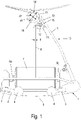
- FIG. 1 shows a schematic plan view of a shuttle 1 according to the invention with a body 2 on which a plurality of rollers 3 and wheels 4 for guiding the shuttle 1 in a reed 5 of a circular loom are attached.
- the body 2 is preferably formed from a one-piece or multi-piece frame.
- On the body 2 of the shuttle 1 there is a holder 6a, 6b for fastening a spool 7, rotatable about its longitudinal axis, on which a weft ribbon 8 is wound. appropriate.
- a weft ribbon insert 10 according to the invention is attached to the body 2 of the shuttle 1 .
- the weft ribbon inserter 10 has an arm 11 on which two deflection wheels 12, 13 for guiding the weft ribbon 8 and an insert wheel 14 are mounted.
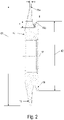
- the insert wheel 14 has a first partial wheel 15 with a first diameter d1 and a second partial wheel 16 with a second diameter d2, the first and the second partial wheel 15, 16 having a common axis of rotation 17 (see FIG 2 ) and are arranged in a rotationally fixed manner with respect to one another.
- the second partial wheel 16 has a weft ribbon guide surface 16a on its circumference.
- the weft ribbon guide surface 16a is designed as a circumferential groove which is narrower than a width b of a weft ribbon 8 to be guided, the circumferential groove preferably being V-shaped or U-shaped in cross section.
- the depth t of the circumferential groove is approximately as large as the width b of the weft ribbon 8, so that the weft ribbon 8 is bent lengthwise in half its legs, with the ribbon being bent again near its longitudinal edges by appropriate measures when guiding the weft ribbon, see 2 .
- the first diameter d1 of the first partial gear 15 is larger than the second diameter d2 of the second partial gear 16, the first diameter d1 of the first partial gear 15 being at least 10%, preferably at least 50% larger than the second diameter d2 of the second partial gear 16 .
- the first partial wheel 15 and the second partial wheel 16 are arranged coaxially next to one another, viewed in the direction of the common axis of rotation 17 , and are designed as a one-piece insert wheel 14 .
- the first partial wheel 15 and the second partial wheel 16 can be designed as individual wheels, which are combined as an insert wheel 14 in a rotationally fixed manner with respect to one another. Provision is made to provide several interchangeable partial wheels 15, 16 with different diameters d1, d2, in order to be able to vary the ratio d1:d2 and thereby the "transmission ratio" of the peripheral speeds of the two partial wheels 15, 16.
- the cross section of the first partial wheel 15 tapers towards its circumference 15a, the first partial wheel 15 having a height h at its circumference 15 that is less than a width b of a weft ribbon 8 to be guided.
- the weft ribbon deflection roller 12 is pivotally mounted on a boom 18 on the arm 11 and forms part of a weft ribbon breakage detector 19.
- the boom 18 is prestressed into a release position by spring means or the like, but is held in place by the weft ribbon 8, which is under tension. which wraps around the deflection roller 12 in part, held away from the release position against the spring means.
- the deflection of this deflection roller 12 depends on the restoring force and the tension of the weft ribbon 8 rotating around the deflection roller 12.
- a permanent magnet, or an inductance, or a capacitance or an optical reflector is/are in/on the deflected weft ribbon - Deflection roller 12 or the boom 18 is arranged (not shown), held outside the operative connection with the sensor 19. If the weft ribbon 8 tears, the restoring force causes the weft ribbon deflection roller 12 to be transported to the release position, where the permanent magnet or the inductance or the capacitance or the optical reflector comes into operative connection with the sensor 19 and the sensor 19 generates an electrical Control signal generated, which stops the circular loom.
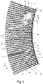
- FIG EP 0 786 026 shows a circular weaving machine 30 schematically and in part.
- FIG EP 0 786 026 shows a circular weaving machine 30 schematically and in part.
- a large number of warp ribbons 31 are fed to the circular loom 30 radially through a circular reed 34 .
- the warp bands 31 are combined into two groups of warp bands 32, 33 (shown in the drawing as light and dark bands of warp 31), with adjacent bands of warp 31 always belonging to different groups of warp bands 32, 33.
- Warp thread lifting means not shown, e.g.
- the weft ribbon inserter 10 located on the shuttle has the function of bringing the weft ribbon 8 as close as possible to the fabric edge 36, and the weft ribbon inserter 10 can have the weft ribbon breakage detector 19 described above.
- the tubular fabric produced in this way is then pulled off via a pull-off ring 37 and wound up folded flat.
- the weft ribbon inserter 10 has the stepped insert wheel 14 with the two different effective diameters d1, d2 of its partial wheels 15, 16.
- the circumference 15a of the larger first partial wheel 15 is guided along the fabric edge 36 and presses the weft ribbon 8 already inserted by the immediately preceding weft ribbon inserter 10 against the fabric edge 36 in order to fix it in the fabric.
- the weft ribbon 8 is continuously released from the second partial wheel 16 with the smaller second diameter d2, which thus has a lower peripheral speed.
- the different peripheral speeds of the first partial wheel 15 and the second partial wheel 16 of the insert wheel 14 result in a constant tensile stress on the inserted weft ribbon.
- This tension of the supplied weft ribbon 8 can be changed by changing the difference in diameter and thus the circumferential speeds of the first partial wheel 15 and the second partial wheel 16 .
- the weft ribbon 8 is guided in a weft ribbon guide surface 16a of the second partial wheel 16, which is designed as a circumferential groove that is narrower than a width b of a weft ribbon 8 to be guided, the circumferential groove is preferably V-shaped or U-shaped in cross-section
- the weft ribbon abrasion is minimized according to the invention in that the weft ribbon 8 is predominantly guided on the rotatable deflection rollers 12, 13 and the insert wheel 14.
- the integrated ribbon breakage detector 19 is also designed with rotating elements in the form of the deflection roller 12 .
- the cross section of the first partial wheel 15 tapers towards its circumference 15a. This "tapering" minimizes the contact surface between the insert wheel 14 and the fabric edge 36 during the fixing of the inserted weft ribbon 8 and there is rolling contact between the weft ribbon insert 10 and the weft ribbon 8 from the preceding one Weft ribbon insert 10, which is pressed.
Landscapes
- Engineering & Computer Science (AREA)
- Textile Engineering (AREA)
- Looms (AREA)
Priority Applications (3)
| Application Number | Priority Date | Filing Date | Title |
|---|---|---|---|
| EP20203512.7A EP3988694A1 (fr) | 2020-10-23 | 2020-10-23 | Roue d'insertion, dispositif d'insertion de bandelette terminale et navette d'un métier circulaire équipée de ladite roue d'insertion et dudit dispositif d'insertion |
| PCT/EP2021/077604 WO2022084044A1 (fr) | 2020-10-23 | 2021-10-06 | Roue d'alimentation, dispositif d'alimentation en rubans en trame et navette d'un métier à tisser circulaire la comprenant |
| TW110139388A TW202219344A (zh) | 2020-10-23 | 2021-10-22 | 嵌輪、引緯器及具有嵌輪、引緯器的圓織機的織梭 |
Applications Claiming Priority (1)
| Application Number | Priority Date | Filing Date | Title |
|---|---|---|---|
| EP20203512.7A EP3988694A1 (fr) | 2020-10-23 | 2020-10-23 | Roue d'insertion, dispositif d'insertion de bandelette terminale et navette d'un métier circulaire équipée de ladite roue d'insertion et dudit dispositif d'insertion |
Publications (1)
| Publication Number | Publication Date |
|---|---|
| EP3988694A1 true EP3988694A1 (fr) | 2022-04-27 |
Family
ID=73014265
Family Applications (1)
| Application Number | Title | Priority Date | Filing Date |
|---|---|---|---|
| EP20203512.7A Withdrawn EP3988694A1 (fr) | 2020-10-23 | 2020-10-23 | Roue d'insertion, dispositif d'insertion de bandelette terminale et navette d'un métier circulaire équipée de ladite roue d'insertion et dudit dispositif d'insertion |
Country Status (3)
| Country | Link |
|---|---|
| EP (1) | EP3988694A1 (fr) |
| TW (1) | TW202219344A (fr) |
| WO (1) | WO2022084044A1 (fr) |
Citations (7)
| Publication number | Priority date | Publication date | Assignee | Title |
|---|---|---|---|---|
| GB190906532A (en) * | 1909-03-18 | 1909-12-16 | Petersen Circular Loom Company | Improvements in and relating to Circular Looms. |
| GB191423060A (en) * | 1914-11-25 | 1915-04-29 | William John Mellersh-Jackson | Improvements in or relating to Circular Looms. |
| DE2415569A1 (de) | 1973-10-12 | 1975-04-24 | Torii Winding Machine Co | Rundwebstuhl |
| AT370787B (de) | 1978-11-29 | 1983-05-10 | Torii Winding Machine Co | Rundwebmaschine |
| AT387797B (de) | 1985-11-26 | 1989-03-10 | Huang Ching Long | Schussfadenwaechter fuer eine rundwebmaschine |
| EP0786026A1 (fr) | 1994-10-20 | 1997-07-30 | STARLINGER & CO. GESELLSCHAFT MBH | Systeme de controle des fils de trame dans un metier a tisser circulaire |
| EP2382347A1 (fr) | 2009-01-22 | 2011-11-02 | Starlinger & Co Gesellschaft m.b.H. | Dispositif de régulation de la tension de rubans en trame sur une navette, navette ainsi configurée et métier à tisser circulaire |
Family Cites Families (3)
| Publication number | Priority date | Publication date | Assignee | Title |
|---|---|---|---|---|
| US3209608A (en) * | 1963-02-18 | 1965-10-05 | Tensitron Inc | Cover for yarn tensioning wheel |
| JPH02293440A (ja) * | 1989-05-02 | 1990-12-04 | Torii Tekkosho:Kk | 円形織機のシャトル支持機構 |
| CN109399333A (zh) * | 2018-11-16 | 2019-03-01 | 刘国军 | 一种纺织机放线器 |
-
2020
- 2020-10-23 EP EP20203512.7A patent/EP3988694A1/fr not_active Withdrawn
-
2021
- 2021-10-06 WO PCT/EP2021/077604 patent/WO2022084044A1/fr not_active Ceased
- 2021-10-22 TW TW110139388A patent/TW202219344A/zh unknown
Patent Citations (7)
| Publication number | Priority date | Publication date | Assignee | Title |
|---|---|---|---|---|
| GB190906532A (en) * | 1909-03-18 | 1909-12-16 | Petersen Circular Loom Company | Improvements in and relating to Circular Looms. |
| GB191423060A (en) * | 1914-11-25 | 1915-04-29 | William John Mellersh-Jackson | Improvements in or relating to Circular Looms. |
| DE2415569A1 (de) | 1973-10-12 | 1975-04-24 | Torii Winding Machine Co | Rundwebstuhl |
| AT370787B (de) | 1978-11-29 | 1983-05-10 | Torii Winding Machine Co | Rundwebmaschine |
| AT387797B (de) | 1985-11-26 | 1989-03-10 | Huang Ching Long | Schussfadenwaechter fuer eine rundwebmaschine |
| EP0786026A1 (fr) | 1994-10-20 | 1997-07-30 | STARLINGER & CO. GESELLSCHAFT MBH | Systeme de controle des fils de trame dans un metier a tisser circulaire |
| EP2382347A1 (fr) | 2009-01-22 | 2011-11-02 | Starlinger & Co Gesellschaft m.b.H. | Dispositif de régulation de la tension de rubans en trame sur une navette, navette ainsi configurée et métier à tisser circulaire |
Also Published As
| Publication number | Publication date |
|---|---|
| TW202219344A (zh) | 2022-05-16 |
| WO2022084044A1 (fr) | 2022-04-28 |
Similar Documents
| Publication | Publication Date | Title |
|---|---|---|
| DE69223575T2 (de) | Selbstregulierende Fadenbremse für eine Schussfadenliefervorrichtung | |
| DE4324412C2 (de) | Vorrichtung zur Einstellung der Fadenspannung | |
| EP0165511B1 (fr) | Dispositif pour bobiner un fil livré à vitesse constante sur une bobine conique | |
| EP3662100B1 (fr) | Ros et métier à tisser circulaire | |
| DE3872557T2 (de) | Vorrichtung und verfahren zum intermittierenden speichern und wiederabgeben von faeden waehrend des aufspulens von konischen spulen mit konstanter fadenzufuehrgeschwindigkeit. | |
| WO1995011183A1 (fr) | Procede et dispositif de guidage d'une bande | |
| EP3257983A1 (fr) | Métier à aiguilles pour tisser les rubans et procédé de tissage correspondant | |
| EP3988694A1 (fr) | Roue d'insertion, dispositif d'insertion de bandelette terminale et navette d'un métier circulaire équipée de ladite roue d'insertion et dudit dispositif d'insertion | |
| EP0443343A1 (fr) | Dispositif pour tisser un tissu à surface rugueuse | |
| DE2643434A1 (de) | Spulenwechselvorrichtung mit einer automatischen trennvorrichtung zum trennen des spulfadens oder bandes | |
| EP0681044A1 (fr) | Procédé et dispositif pour évacuer les déchets de faux lisières | |
| AT525087B1 (de) | Rundwebmaschine zur Herstellung eines Rundgewebes | |
| DE4121781A1 (de) | Getriebe fuer textilmaschinen insbesondere zum verhindern von bildwicklungen beim aufwinden von faeden | |
| DE4014759C2 (fr) | ||
| AT521026B1 (de) | Vorrichtung zur Herstellung einer geflochtenen Ummantelung | |
| DE1035231B (de) | Bandzugsteuervorrichtung fuer eine Maschine zum Bewickeln elektrischer Kabel | |
| DE102018212847B3 (de) | Vorrichtung zum Einstellen der Kettspannung von Kettfäden | |
| EP1217115A1 (fr) | Dispositif d'entraínement du chariot porte-couteau sur un métier à tisser les tapis doubles | |
| DE69305028T2 (de) | Verbesserung von Schussfadenliefervorrichtungen für pneumatische Webmaschinen | |
| DE19703002A1 (de) | Vorrichtung zum Schären einer Fadenschar auf einem Kettbaum | |
| AT526867B1 (de) | Rundwebmaschine zur Herstellung eines Rundgewebes | |
| EP2784196B1 (fr) | Ourdissoir à chaîne | |
| DE19626417A1 (de) | Frottierwebmaschine mit Florkettspannungskompensation | |
| DE2463074C2 (de) | Einprozeß-Zwirnmaschine zur Erzeugung von Zwirn aus zwei Strängen | |
| DE3877927T2 (de) | Drehbares spiralelement zur erzeugung des fadenspannungsausgleichs und des falschdrehens in einem textilen faserband. |
Legal Events
| Date | Code | Title | Description |
|---|---|---|---|
| PUAI | Public reference made under article 153(3) epc to a published international application that has entered the european phase |
Free format text: ORIGINAL CODE: 0009012 |
|
| STAA | Information on the status of an ep patent application or granted ep patent |
Free format text: STATUS: THE APPLICATION HAS BEEN PUBLISHED |
|
| AK | Designated contracting states |
Kind code of ref document: A1 Designated state(s): AL AT BE BG CH CY CZ DE DK EE ES FI FR GB GR HR HU IE IS IT LI LT LU LV MC MK MT NL NO PL PT RO RS SE SI SK SM TR |
|
| STAA | Information on the status of an ep patent application or granted ep patent |
Free format text: STATUS: THE APPLICATION IS DEEMED TO BE WITHDRAWN |
|
| 18D | Application deemed to be withdrawn |
Effective date: 20221028 |