EP3984928B1 - Dockschutzmodul mit doppeltor und luftvorhang - Google Patents
Dockschutzmodul mit doppeltor und luftvorhang Download PDFInfo
- Publication number
- EP3984928B1 EP3984928B1 EP20822754.6A EP20822754A EP3984928B1 EP 3984928 B1 EP3984928 B1 EP 3984928B1 EP 20822754 A EP20822754 A EP 20822754A EP 3984928 B1 EP3984928 B1 EP 3984928B1
- Authority
- EP
- European Patent Office
- Prior art keywords
- gate
- warehouse
- air
- loading
- channel
- Prior art date
- Legal status (The legal status is an assumption and is not a legal conclusion. Google has not performed a legal analysis and makes no representation as to the accuracy of the status listed.)
- Active
Links
Images


Classifications
-
- B—PERFORMING OPERATIONS; TRANSPORTING
- B65—CONVEYING; PACKING; STORING; HANDLING THIN OR FILAMENTARY MATERIAL
- B65G—TRANSPORT OR STORAGE DEVICES, e.g. CONVEYORS FOR LOADING OR TIPPING, SHOP CONVEYOR SYSTEMS OR PNEUMATIC TUBE CONVEYORS
- B65G69/00—Auxiliary measures taken, or devices used, in connection with loading or unloading
- B65G69/28—Loading ramps; Loading docks
- B65G69/287—Constructional features of deck or surround
-
- G—PHYSICS
- G07—CHECKING-DEVICES
- G07C—TIME OR ATTENDANCE REGISTERS; REGISTERING OR INDICATING THE WORKING OF MACHINES; GENERATING RANDOM NUMBERS; VOTING OR LOTTERY APPARATUS; ARRANGEMENTS, SYSTEMS OR APPARATUS FOR CHECKING NOT PROVIDED FOR ELSEWHERE
- G07C9/00—Individual registration on entry or exit
- G07C9/00174—Electronically operated locks; Circuits therefor; Nonmechanical keys therefor, e.g. passive or active electrical keys or other data carriers without mechanical keys
- G07C9/00563—Electronically operated locks; Circuits therefor; Nonmechanical keys therefor, e.g. passive or active electrical keys or other data carriers without mechanical keys using personal physical data of the operator, e.g. finger prints, retinal images, voicepatterns
-
- B—PERFORMING OPERATIONS; TRANSPORTING
- B65—CONVEYING; PACKING; STORING; HANDLING THIN OR FILAMENTARY MATERIAL
- B65G—TRANSPORT OR STORAGE DEVICES, e.g. CONVEYORS FOR LOADING OR TIPPING, SHOP CONVEYOR SYSTEMS OR PNEUMATIC TUBE CONVEYORS
- B65G1/00—Storing articles, individually or in orderly arrangement, in warehouses or magazines
- B65G1/02—Storage devices
- B65G1/04—Storage devices mechanical
-
- B—PERFORMING OPERATIONS; TRANSPORTING
- B65—CONVEYING; PACKING; STORING; HANDLING THIN OR FILAMENTARY MATERIAL
- B65G—TRANSPORT OR STORAGE DEVICES, e.g. CONVEYORS FOR LOADING OR TIPPING, SHOP CONVEYOR SYSTEMS OR PNEUMATIC TUBE CONVEYORS
- B65G67/00—Loading or unloading vehicles
- B65G67/02—Loading or unloading land vehicles
-
- B—PERFORMING OPERATIONS; TRANSPORTING
- B65—CONVEYING; PACKING; STORING; HANDLING THIN OR FILAMENTARY MATERIAL
- B65G—TRANSPORT OR STORAGE DEVICES, e.g. CONVEYORS FOR LOADING OR TIPPING, SHOP CONVEYOR SYSTEMS OR PNEUMATIC TUBE CONVEYORS
- B65G69/00—Auxiliary measures taken, or devices used, in connection with loading or unloading
- B65G69/008—Dock- or bumper-seals
-
- B—PERFORMING OPERATIONS; TRANSPORTING
- B65—CONVEYING; PACKING; STORING; HANDLING THIN OR FILAMENTARY MATERIAL
- B65G—TRANSPORT OR STORAGE DEVICES, e.g. CONVEYORS FOR LOADING OR TIPPING, SHOP CONVEYOR SYSTEMS OR PNEUMATIC TUBE CONVEYORS
- B65G69/00—Auxiliary measures taken, or devices used, in connection with loading or unloading
- B65G69/28—Loading ramps; Loading docks
-
- E—FIXED CONSTRUCTIONS
- E06—DOORS, WINDOWS, SHUTTERS, OR ROLLER BLINDS IN GENERAL; LADDERS
- E06B—FIXED OR MOVABLE CLOSURES FOR OPENINGS IN BUILDINGS, VEHICLES, FENCES OR LIKE ENCLOSURES IN GENERAL, e.g. DOORS, WINDOWS, BLINDS, GATES
- E06B9/00—Screening or protective devices for wall or similar openings, with or without operating or securing mechanisms; Closures of similar construction
- E06B9/56—Operating, guiding or securing devices or arrangements for roll-type closures; Spring drums; Tape drums; Counterweighting arrangements therefor
- E06B9/58—Guiding devices
-
- F—MECHANICAL ENGINEERING; LIGHTING; HEATING; WEAPONS; BLASTING
- F24—HEATING; RANGES; VENTILATING
- F24F—AIR-CONDITIONING; AIR-HUMIDIFICATION; VENTILATION; USE OF AIR CURRENTS FOR SCREENING
- F24F9/00—Use of air currents for screening, e.g. air curtains
-
- F—MECHANICAL ENGINEERING; LIGHTING; HEATING; WEAPONS; BLASTING
- F24—HEATING; RANGES; VENTILATING
- F24F—AIR-CONDITIONING; AIR-HUMIDIFICATION; VENTILATION; USE OF AIR CURRENTS FOR SCREENING
- F24F9/00—Use of air currents for screening, e.g. air curtains
- F24F2009/005—Use of air currents for screening, e.g. air curtains combined with a door
-
- F—MECHANICAL ENGINEERING; LIGHTING; HEATING; WEAPONS; BLASTING
- F24—HEATING; RANGES; VENTILATING
- F24F—AIR-CONDITIONING; AIR-HUMIDIFICATION; VENTILATION; USE OF AIR CURRENTS FOR SCREENING
- F24F9/00—Use of air currents for screening, e.g. air curtains
- F24F2009/007—Use of air currents for screening, e.g. air curtains using more than one jet or band in the air curtain
-
- G—PHYSICS
- G08—SIGNALLING
- G08B—SIGNALLING SYSTEMS, e.g. PERSONAL CALLING SYSTEMS; ORDER TELEGRAPHS; ALARM SYSTEMS
- G08B21/00—Alarms responsive to a single specified undesired or abnormal condition and not otherwise provided for
- G08B21/18—Status alarms
Definitions
- WO 82/02934 A1 discloses a dock shelter module comprising a top frame and side frames, a first gate and an air curtain generator installed on a bottom of the top frame and forming an air curtain dependent from whether the first gate is open or closed.
- the dock seal or dock gate is installed on a wall of the dock
- FIG. 1 is a view showing a dock system having a sealing structure of the related art.
- a dock system of the related art is configured to effectively seal a front space and a side space using a front sealing part and side sealing parts.
- the dock system of the related art also has the problem that air freely flows inside and outside a warehouse from the process of loading freight to the process of opening and closing a door. Further, the dock system has a single sealing unit, so there is a problem that the sealing ability is insufficient and appropriate sealing according to the sizes of vehicles is impossible.
- Prior Art Document Korean Patent NO. 10-1950696
- the present disclosure has been made in an effort to solve the problems of the related art and an objective of the present disclosure is to provide a dock shelter module of which the sealing ability is improved by forming a loading-unloading space with a top frame, side frames, and a bottom frame and disposing a dual gate at the front and rear, that can prevent air from flowing inside and outside a warehouse in loading and unloading by having an air curtain generator, and that forms an appropriate sealing structure regardless of the sizes of transport vehicle.
- the top frame may include a top channel and a top valve selectively controlling the flow of air, in which the top channel may include a first top channel of which an end is connected with the inside of the warehouse and the other end is connected to the top valve, a second top channel of which an end is connected with the outside of the warehouse and the other end is connected to the top valve, and a third top channel of which an end is connected to the air curtain generator and the other end is connected to the top valve.
- the bottom frame may include a bottom channel communicating with the bottom frame and the inside and outside of the warehouse, and a bottom valve selectively controlling the flow of bottom air.
- the dock shell module further includes an opening-closing sensor that senses whether the first gate and the second gate are opened and closed, and a controller that controls the top valve and the bottom valve and controls operation of the air curtain generator so that an air curtain is formed in accordance with whether the gates are opened and closed.
- the side frames may have guides for guiding up-down movement of the first gate and the second gate
- the top frame may have a winder that winds and keeps the first gate and the second gate at the lower end of the top frame.
- the dock shelter module may further include a security module that requires input of pre-stored user information to open the first gate and the second gate, in which the user information and information about opening and closing may be transmitted and stored in a server.
- the closing speed of the first gate is set faster than the closing speed of the second gate when the first gate and the second gate are closed.
- the dock shell module may further include a sealing device that is disposed in the top frame, the side frames, and the bottom frame, and seals gaps by moving when a transport vehicle "is connected to the warehouse, and the sealing device may have air spray nozzles for spraying air.
- the bottom frame may further include a drying device and a drying spray nozzle for drying and sterilizing the loading-unloading space after loading/unloading is finished.
- the second gate may have a reflective plate on a first surface thereof that faces the inside of the warehouse, and may have an air-pocket insulator on a second surface thereof that faces the loading-unloading space, thereby having a dual structure.
- a dual gate is provided ahead of and behind a loading-unloading space, it is possible to effectively isolate the inside and outside of a warehouse not only during loading/unloading, but in normal time.
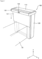
- FIG. 7 is a view showing the state in which a dock shelter module according to a first embodiment of the present disclosure is installed at a warehouse.
- the dock shelter module 10 may further include a security module 400 that requires input of pre-stored user information to open the first gate 210 and the second gate 220.
- a security module 400 that requires input of pre-stored user information to open the first gate 210 and the second gate 220.
- information of the date and time of opening and closing the first gate 210 and the second gate 220 can be transmitted and stored to a separate server together with the user information.
- a separate management server connected with the security module 400 through wireless communication may be provided, which is not described in detail as the related art.
- the loading-unloading space When cold air is sprayed and the loading-unloading space is closed during loading/unloading, the cold air in the loading-unloading space condensates, so dew condensation may occur. Accordingly, the loading-unloading space may be contaminated, or a safety accident may occur in the following loading/unloading. Therefore, it is possible to dry the loading-unloading space by spraying hot air.
- the cold air flows to the bottom frame 150 and flows into the third bottom channel 343 connected to the bottom frame 150.
- the air flowing in the third bottom channel 343 flows to the bottom valve 330.
- the bottom valve 330 is set such that the third bottom channel 343 and the first bottom channel 341 communicate with each other with the first gate 210 and the second gate 220 open. Accordingly, the air flowing inside can flow to the first bottom channel 341 and can be discharged back into the warehouse.
- a fan that make the flow of air smooth may be further disposed in the top channel 320 and the bottom channel 340, whereby air is enabled to smoothly flow inside and outside.
- FIG. 6 is a block diagram schematically showing operation of the dock shelter module according to the first embodiment of the present disclosure.
- the controller 900 can output an operation signal of the air curtain generator 300 and can control the top valve 310 such that the first top channel 321 and the third top channel 323 communicate with each other.
- the controller 900 can control the top valve 310 such that the second top channel 322 and the third top channel 323 communicate with each other.
- the controller 900 may control operation of the heater.
- the controller 900 may output an operation stop signal of the air curtain generator 300 after a predetermined time passes.
- the controller 900 can control the bottom valve 330 such that the second bottom channel 342 and the third bottom channel 343 communicate with each other. Accordingly, when the first gate 210 and the second gate are closed, external air flows into the air curtain generator 300 and sprayed. The sprayed air is discharged outside through the bottom channel 340, whereby air can be circulated.
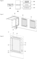
- FIG. 8 is a view showing the state in which a dock shelter module according to a second embodiment of the present disclosure is equipped with a sealing device
- FIG. 9 is a view showing the state in which the sealing device of the dock shelter module according to the second embodiment of the present disclosure is connected to a freight compartment of a transport vehicle.
- a dock shelter module 10 may further include a sealing device 500.
- the sealing device 500 can seal the gaps between the freight compartment, the top frame, the side frames, and the bottom frame.
- the entire sealing device 500 or the portion thereof that is in contact with the transport vehicle 20 may be made of an electromagnet.
- a current flows, so magnetism is generated. Accordingly, they are strongly connected by the magnetic force, whereby the gaps can be effectively sealed. Further, after loading/unloading is finished, the current is removed, and the sealing device can be easily separated from the freight compartment.
- Air spray nozzles 510 that spray air to the surface that is connected to a freight compartment may be disposed at the rectangular frames of the sealing device 500.
- air can be sprayed forward from the air spray nozzles 510.
- the freight compartment of the transport vehicle 20 is uneven, so it is difficult to completely come in close contact with the sealing device 500. Accordingly, it is possible to prevent dust, insects, etc. from entering the gap between the frames and the freight compartment by spraying air through the air spray nozzles 510.
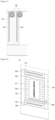
- FIG. 10 is a view showing the state in which a dock shelter module according to a third embodiment of the present disclosure is equipped with a dryer and drying spray nozzles.
- a drying device 600 may be installed at the bottom frame 150.
- the drying device 600 may include one or more spray nozzles 610 that spray a drying substance to the bottom frame 150.
- the drying device 600 may be a steam device that is a device of liquid, etc. treated with water or a chemical into high-temperature and high-pressure steam, or may be a microwave device.
- the drying spray nozzles 610 are installed at the drying device 600 and can spray high-temperature and high-pressure steam or microwaves to the loading-unloading space.
- drying device 600 and the drying spray nozzles 610 are installed at the bottom frame 150, but the drying device 600 and the drying spray nozzles 610 may be installed at the top frame 110 or the side frames 130 to dry the loading-unloading space.
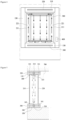
- FIG. 11 is a view showing the state in which a dock shelter module according to a fourth embodiment of the present disclosure is equipped with a winder.
- the side frames 130 may include guides 211 and 212, in which the first gate 210 and the second gate 220 are inserted to be guided up and down, on a surface on which the loading-unloading space is formed by the side frames 130.
- a winder 700 that winds the upper portions of the first gate 210 and the second gate 220 under the top frame 110 when the first gate 210 and the second gate 220 are opened may be disposed at the top frame 110.
- the first gate 210 and the second gate 220 are opened for loading/unloading, the first gate 210 and the second gate 220 can be lifted along the guides 211 and 221 and wound and kept on the winder 700.
- FIG. 12 is a cross-sectional view showing the state in which a commercial video is sent out on a first gate of a dock shelter module according to a fifth embodiment of the present disclosure.
- the first gate 210 may be made of a transparent material and a video device (not shown) that outputs a video to the first gate 210 may be further included.
- the video device outputs a video to the front surface of the first gate 210, whereby the output video image can be displayed on the first gate.
- a commercial video is produced and output, it is possible to see the commercial video displayed on the first gate 210 from the outside of the warehouse, so an advertisement and information effect can be achieved.
- the dock shelter modules according to the second to fifth embodiments are the same as in the other configuration except for the additional configuration separately described above, as compared with the dock shelter module according to the first embodiment. Accordingly, the configuration not specifically described can be applied to the second to fifth embodiments in the same way, and accordingly, repeated description is omitted.
Landscapes
- Engineering & Computer Science (AREA)
- Mechanical Engineering (AREA)
- Chemical & Material Sciences (AREA)
- Combustion & Propulsion (AREA)
- General Engineering & Computer Science (AREA)
- Structural Engineering (AREA)
- Architecture (AREA)
- Civil Engineering (AREA)
- Physics & Mathematics (AREA)
- General Physics & Mathematics (AREA)
- Aviation & Aerospace Engineering (AREA)
- Devices That Are Associated With Refrigeration Equipment (AREA)
- Refrigerator Housings (AREA)
Claims (15)
- Laderampenschutzmodul (10), das konfiguriert ist, an einer Seite einer Lagerhalle angeordnet zu werden, und konfiguriert ist, den Innenraum und den Außenraum der Lagerhalle zu verbinden, wobei das Laderampenschutzmodul (10) umfasst:einen oberen Rahmen (110);ein Paar Seitenrahmen (130), die an beiden Seiten des oberen Rahmens (110) gekoppelt sind, sich längs erstrecken und in Zusammenwirkung mit dem oberen Rahmen einen Lade-/Entlade-Raum bilden;einen unteren Rahmen (150), der an die unteren Enden der Seitenrahmen (130) gekoppelt ist und einen auf ihm gelegenen Laderampenhöhenausgleicher besitzt;ein erstes Tor (210), das an den oberen Rahmen (110) gekoppelt ist, an der Vorderseite des Lade-/Entlade-Raums angeordnet ist und den Außenraum der Lagerhalle und des Lade-/Entlade-Raums öffnet und schließt;ein zweites Tor (220), das an den oberen Rahmen (110) gekoppelt ist, an der Rückseite des Lade-/Entlade-Raums angeordnet ist und den Innenraum der Lagerhalle und des Lade-/Entlade-Raums öffnet und schließt; undeinen Luftvorhangerzeuger (200), der auf der Unterseite des oberen Rahmens (110) zwischen dem ersten Tor (210) und dem zweiten Tor (220) angeordnet ist und einen Luftvorhang in dem Lade-/Entlade-Raum in Übereinstimmung damit, ob das erste Tor (210) und das zweite Tor (220) geöffnet und geschlossen sind, bildet.
- Laderampenschutzmodul nach Anspruch 1, wobei der obere Rahmen enthält:einen oberen Kanal (320), der mit dem Luftvorhangerzeuger (300) und dem Innenraum und dem Außenraum der Lagerhalle kommuniziert; undein oberes Ventil (310), das in dem oberen Kanal angeordnet ist, konfiguriert ist, den Luftstrom wahlweise derart zu steuern, dass kalte Luft in der Lagerhalle in den Luftvorhangerzeuger fließt und ein Luftvorhang in dem Lade-/Entlade-Raum gebildet wird, und derart, dass Luft außerhalb der Lagerhalle in den Luftvorhangerzeuger (300) fließt und ein Luftvorhang gebildet wird, um den Lade-/Entlade-Raum zu trocknen, nachdem das Laden/Entladen abgeschlossen ist.
- Laderampenschutzmodul (10) nach Anspruch 2, wobei der obere Kanal enthält:einen ersten oberen Kanal (321), wovon ein Ende mit dem Innenraum der Lagerhalle verbunden ist und wovon das andere Ende mit dem oberen Ventil verbunden ist, so dass kalte Luft in der Lagerhalle in den oberen Kanal fließt;einen zweiten oberen Kanal (322), wovon ein Ende mit dem Außenraum der Lagerhalle verbunden ist und wovon das andere Ende mit dem oberen Ventil (310) verbunden ist, so dass Luft außerhalb der Lagerhalle in den oberen Kanal (320) fließt; undeinen dritten oberen Kanal (323), wovon ein Ende mit dem Luftvorhangerzeuger verbunden ist und wovon das andere Ende mit dem oberen Ventil (310) verbunden ist, so dass Luft, die innerhalb des oberen Ventils fließt, zu dem Luftvorhangerzeuger (300) fließt,wodurch Luft, die zu dem Luftvorhangerzeuger (300) fließt, wahlweise gesteuert werden kann.
- Laderampenschutzmodul (10) nach Anspruch 3, wobei der untere Rahmen (150) enthält:einen unteren Kanal (340), der mit dem unteren Rahmen und dem Innenraum und dem Außenraum der Lagerhalle kommuniziert; undein unteres Ventil (330), das in dem unteren Kanal (340) angeordnet ist und wahlweise den Luftstrom steuert,
undwobei der obere Kanal (320) enthält:einen ersten unteren Kanal (341), wovon ein Ende mit dem Innenraum der Lagerhalle verbunden ist und wovon das andere Ende mit dem unteren Ventil verbunden ist, so dass Luft, die von dem Luftvorhangerzeuger gesprüht wird, in die Lagerhalle ausgestoßen wird;einen zweiten unteren Kanal (342), wovon ein Ende mit dem Außenraum der Lagerhalle verbunden ist und wovon das andere Ende mit dem unteren Ventil verbunden ist, so dass Luft, die einen Luftvorhang bildet, aus der Lagerhalle heraus ausgestoßen wird; undeinen dritten unteren Kanal (343), wovon ein Ende mit der Unterseite des unteren Rahmens (150) verbunden ist und wovon das andere Ende mit dem unteren Ventil (330) verbunden ist, so dass Luft von dem Luftvorhangerzeuger (300) zu dem unteren Ventil (330) gesprüht wird,wobei Luft, die zu dem Luftvorhangerzeuger (300) fließt, wahlweise umgewälzt werden kann. - Laderampenschutzmodul nach Anspruch 4, das ferner umfasst:einen Öffnungs-Schließ-Sensor (800), der konfiguriert ist, zu erfassen, ob das erste Tor und das zweite Tor geöffnet und geschlossen sind; undeine Steuereinheit (900), die das obere Ventil (310) und das untere Ventil (330) steuert und einen Betrieb des Luftvorhangerzeugers steuert,wobei die Steuereinheit (900) konfiguriert ist, ein Betriebssignal des Luftvorhangerzeugers (300) auszugeben und das obere Ventil (310) derart zu steuern, dass der erste obere Kanal (321) und der dritte obere Kanal (323) miteinander kommunizieren, wenn der Öffnungs-Schließ-Sensor (800) ein Öffnen des ersten Tors (210) und des zweiten Tors (220) erfasst, undkonfiguriert ist, das obere Ventil (310) derart zu steuern, dass der zweite obere Kanal (322) und der dritte obere Kanal (323) miteinander kommunizieren, wenn das erste Tor (210) und das zweite Tor (220) geschlossen sind, und konfiguriert ist, ein Betriebsstoppsignal des Luftvorhangerzeugers (300) auszugeben, um automatisch einen Luftvorhang in Übereinstimmung damit, dass die Tore geöffnet oder geschlossen sind, nachdem eine vorgegebene Zeit vergangen ist, zu bilden.
- Laderampenschutzmodul nach Anspruch 5, wobei die Steuereinheit das untere Ventil (330) derart steuert, dass der erste untere Kanal (341) und der dritte untere Kanal (343) miteinander kommunizieren, wenn der Öffnungs-Schließ-Sensor (800) erfasst, dass sich das erste Tor (210) und das zweite Tor (220) geöffnet haben, und
das untere Ventil (343) derart steuert, dass der zweite untere Kanal (342) und der dritte untere Kanal (343) miteinander kommunizieren, wenn der Öffnungs-Schließ-Sensor (800) erfasst, dass sich das erste Tor und das zweite Tor geschlossen haben. - Laderampenschutzmodul nach Anspruch 1, das ferner eine Aufwickelmaschine (700) umfasst, die das erste Tor und das zweite Tor an dem unteren Ende des oberen Rahmens aufwickelt und hält, wenn das erste Tor und das zweite Tor geöffnet werden,
wobei die Seitenrahmen Führungen besitzen, in die das erste Tor und das zweite Tor eingeführt werden, um auf einer Fläche, auf der die Seitenrahmen einen Lade-/Entlade-Raum bilden, hoch und runter geführt zu werden. - Laderampenschutzmodul nach Anspruch 1, das ferner ein Sicherheitsmodul (400) umfasst, das eine Eingabe von im Voraus gespeicherten Anwenderinformationen benötigt, um das erste Tor und das zweite Tor zu öffnen,
wobei die Anwenderinformationen und Informationen über das Öffnen und Schließen gesendet und in einem Server gespeichert werden und/oder wobei das Sicherheitsmodul ein Fingerabdruckmodul oder ein Irismodul ist. - Laderampenschutzmodul nach Anspruch 1, wobei die Schließgeschwindigkeit des ersten Tors schneller eingestellt ist als die Schließgeschwindigkeit des zweiten Tors, wenn das erste Tor und das zweite Tor geschlossen werden, um den Lade-/Entlade-Raum zu schließen, um zu verhindern, dass kalte Luft in der Lagerhalle nach draußen fließt.
- Laderampenschutzmodul nach Anspruch 1, das ferner eine Dichtungsvorrichtung umfasst, die konfiguriert ist, Lücken zwischen einem Frachtabteil eines Transportfahrzeugs, dem oberen Rahmen, den Seitenrahmen und dem unteren Rahmen abzudichten, wenn das Transportfahrzeug mit der Lagerhalle verbunden wird,
wobei die Dichtungsvorrichtung aus vier rechteckigen Rahmen eines oberen, eines unteren, eines linken und eines rechten Rahmens besteht, die jeweils in dem oberen Rahmen, den Seitenrahmen und dem unteren Rahmen angeordnet sind und mit einem Frachtabteil eines Transportfahrzeugs in engen Kontakt kommen, indem das Transportfahrzeug bewegt wird, wenn das Transportfahrzeug mit der Lagerhalle verbunden wird; und/oder wobei die Dichtungsvorrichtung Luftspraydüsen enthält, die auf Flächen der rechteckigen Rahmen, die mit dem Frachtrahmen in engen Kontakt gebracht werden und Luft sprühen, angeordnet sind. - Laderampenschutzmodul nach Anspruch 1, das ferner eine Trocknungsvorrichtung und eine Trocknungsspraydüse zum Trocknen und Sterilisieren des Lade-/Entlade-Raums, nachdem das Laden/Entladen abgeschlossen ist, umfasst.
- Laderampenschutzmodul nach Anspruch 11, wobei die Trocknungsvorrichtung eine Dampfvorrichtung oder eine Mikrowellenvorrichtung ist.
- Laderampenschutzmodul nach Anspruch 1, wobei das zweite Tor eine reflektive Platte auf einer ersten Fläche von ihm besitzt, die dem Innenraum der Lagerhalle zugewandt ist, und einen Lufttaschenisolator auf einer zweiten Fläche von ihm besitzt, die dem Lade-/Entlade-Raum zugewandt ist, wodurch es eine doppelte Struktur besitzt.
- Laderampenschutzmodul nach Anspruch 1, das ferner einen Puffer umfasst, der Erschütterungen abschwächt und an dem oberen Rahmen, den Seitenrahmen und dem unteren Rahmen angeordnet ist,
wobei der Puffer einen Sensor enthält, der ein Annähern erkennt, wenn sich ein Transportfahrzeug annähert, und einen Signalalarm aussendet, wenn sich das Transportfahrzeug innerhalb eines vorgegebenen Abstands annähert. - Laderampenschutzmodul nach Anspruch 1, wobei das erste Tor aus einem transparenten Material hergestellt ist und
das Laderampenschutzmodul ferner eine Videovorrichtung umfasst, die ein Video auf der Vorderfläche des ersten Tors derart ausgibt, dass ein kommerzielles Video gesehen werden kann, während das erste Tor geschlossen ist.
Applications Claiming Priority (2)
| Application Number | Priority Date | Filing Date | Title |
|---|---|---|---|
| KR1020190069742A KR102090118B1 (ko) | 2019-06-13 | 2019-06-13 | 이중 게이트 및 에어 커튼을 구비한 도크 쉘터 모듈 |
| PCT/KR2020/007620 WO2020251292A1 (ko) | 2019-06-13 | 2020-06-12 | 이중 게이트 및 에어 커튼을 구비한 도크 쉘터 모듈 |
Publications (3)
| Publication Number | Publication Date |
|---|---|
| EP3984928A1 EP3984928A1 (de) | 2022-04-20 |
| EP3984928A4 EP3984928A4 (de) | 2023-04-12 |
| EP3984928B1 true EP3984928B1 (de) | 2024-07-10 |
Family
ID=70003932
Family Applications (1)
| Application Number | Title | Priority Date | Filing Date |
|---|---|---|---|
| EP20822754.6A Active EP3984928B1 (de) | 2019-06-13 | 2020-06-12 | Dockschutzmodul mit doppeltor und luftvorhang |
Country Status (5)
| Country | Link |
|---|---|
| US (1) | US12217561B2 (de) |
| EP (1) | EP3984928B1 (de) |
| KR (1) | KR102090118B1 (de) |
| CN (1) | CN113939463B (de) |
| WO (1) | WO2020251292A1 (de) |
Families Citing this family (10)
| Publication number | Priority date | Publication date | Assignee | Title |
|---|---|---|---|---|
| KR102090118B1 (ko) * | 2019-06-13 | 2020-03-17 | 김재중 | 이중 게이트 및 에어 커튼을 구비한 도크 쉘터 모듈 |
| KR102303758B1 (ko) * | 2021-05-21 | 2021-09-16 | 김유곤 | 드라이룸의 국부 제습을 위한 다단 제습 시스템 |
| CN115584912A (zh) * | 2022-09-14 | 2023-01-10 | 青岛海尔生物医疗股份有限公司 | 生物样本采集窗、采样舱 |
| KR20240054460A (ko) * | 2022-10-18 | 2024-04-26 | 현대자동차주식회사 | 차량과 건물의 도킹 시스템 및 그를 위한 제어 방법 |
| KR102826154B1 (ko) * | 2022-12-05 | 2025-06-27 | 주식회사 아이도어랩 | 물류 자동 운송이 가능한 고정형 지게로봇과 이송 컨베이어 저온작업장화를 위한 에어월 구조물을 구비하는 물류 운송 시스템 |
| KR102903439B1 (ko) * | 2022-12-05 | 2025-12-23 | 주식회사 아이도어랩 | 간편설치가 가능한 사전조립 모듈형 도크 장치 |
| CA3214523A1 (en) * | 2023-06-16 | 2025-06-17 | Ultra-Lite Overhead Doors Ltd. | Dock door screen assembly and method of use thereof |
| DE102023119169B3 (de) * | 2023-07-20 | 2024-10-24 | ASMPT GmbH & Co. KG | Aufnahmevorrichtung und Aufnahmeverfahren |
| JP7572529B1 (ja) * | 2023-11-02 | 2024-10-23 | 博則 稲富 | 倉庫出入口ガード機構 |
| KR102727222B1 (ko) * | 2023-12-19 | 2024-11-07 | 주식회사 아이도어랩 | 도크 씰 |
Family Cites Families (25)
| Publication number | Priority date | Publication date | Assignee | Title |
|---|---|---|---|---|
| WO1982002934A1 (en) * | 1981-02-24 | 1982-09-02 | Vahl Laszlo | Cold-storage building |
| DE3206958C2 (de) * | 1982-02-26 | 1986-09-18 | Schott Glaswerke, 6500 Mainz | Phototropes Glas mit einem Brechungsindex ≥ 1,59, einer Abbezahl ≥ 44 und einer Dichte ≦ 3,0 g/cm↑3↑ |
| JP2002302213A (ja) * | 2001-03-30 | 2002-10-18 | Sanyo Electric Co Ltd | 低温物品搬入設備 |
| US20030145535A1 (en) * | 2002-02-06 | 2003-08-07 | Dibiase Joseph J. | Lead-in bumper for a loading dock |
| JP3897732B2 (ja) * | 2002-06-17 | 2007-03-28 | 株式会社前川製作所 | エアシャッタ及びその設置方法 |
| WO2004079281A2 (en) * | 2003-01-14 | 2004-09-16 | Hcr Incorporated | Conditioned vestibule for a cold storage doorway |
| EP2428474B1 (de) * | 2003-02-10 | 2014-12-17 | Niclas Grunewald | Verfahren zum Betrieb eines Anfahrschutzes |
| TWI296321B (en) * | 2003-05-27 | 2008-05-01 | Maekawa Seisakusho Kk | Air shutter and installation method thereof |
| EP1703825A4 (de) * | 2004-01-06 | 2007-09-26 | Carrier Comm Refrigeration Inc | Kühlauslage mit verbessertem luftvorhang |
| CA2499090A1 (en) * | 2004-03-02 | 2005-09-02 | Asi Technologies, Inc. | Air curtain doorway |
| CN2831321Y (zh) * | 2005-06-24 | 2006-10-25 | 喻天祥 | 公交车投币机广告灯箱 |
| US20080104902A1 (en) * | 2006-11-07 | 2008-05-08 | Rite-Hite Holding Corporation | Low profile support panel for a dock seal |
| US20090291627A1 (en) * | 2008-05-20 | 2009-11-26 | Zimmermann Charles A | Air Curtain Doorway With Integrated Doors |
| CA2691245C (en) * | 2009-01-28 | 2018-09-25 | Bryn Gough Magee | Enhanced entranceway |
| US8672427B2 (en) * | 2010-01-25 | 2014-03-18 | Pepsico, Inc. | Video display for product merchandisers |
| CN102607226B (zh) * | 2012-04-27 | 2013-08-28 | 浙江科技学院 | 一种冷库的短时隔离气帘及其控制方法 |
| KR101379909B1 (ko) * | 2013-03-22 | 2014-04-02 | 김재중 | 실린더 타입의 밀폐부재와 완충부재가 구비된 쉘터 |
| JP6268425B2 (ja) * | 2013-07-16 | 2018-01-31 | シンフォニアテクノロジー株式会社 | Efem、ロードポート、ウェーハ搬送方法 |
| US20180108192A1 (en) * | 2014-12-23 | 2018-04-19 | Gate Labs Inc. | Access management system |
| KR101950696B1 (ko) | 2016-08-08 | 2019-02-21 | 한국철도기술연구원 | 밀폐 구조를 갖는 도크 시스템 |
| KR20180038091A (ko) * | 2016-10-05 | 2018-04-16 | 주식회사 이토피아이앤씨 | 공기정화 버스 쉘터 |
| KR101834863B1 (ko) * | 2016-10-28 | 2018-04-23 | 한국철도기술연구원 | 가변 동선을 위한 통로 폭 조절 장치 |
| JP6411582B1 (ja) * | 2017-06-02 | 2018-10-24 | 日本エアーテック株式会社 | エアーカーテン装置 |
| CN208236291U (zh) * | 2018-05-11 | 2018-12-14 | 四川泓炜特种门业有限责任公司 | 一种防火卷帘门 |
| KR102090118B1 (ko) | 2019-06-13 | 2020-03-17 | 김재중 | 이중 게이트 및 에어 커튼을 구비한 도크 쉘터 모듈 |
-
2019
- 2019-06-13 KR KR1020190069742A patent/KR102090118B1/ko active Active
-
2020
- 2020-06-12 WO PCT/KR2020/007620 patent/WO2020251292A1/ko not_active Ceased
- 2020-06-12 CN CN202080042349.5A patent/CN113939463B/zh active Active
- 2020-06-12 EP EP20822754.6A patent/EP3984928B1/de active Active
- 2020-06-12 US US17/617,474 patent/US12217561B2/en active Active
Also Published As
| Publication number | Publication date |
|---|---|
| EP3984928A4 (de) | 2023-04-12 |
| KR102090118B9 (ko) | 2023-02-21 |
| WO2020251292A1 (ko) | 2020-12-17 |
| CN113939463A (zh) | 2022-01-14 |
| US20220237968A1 (en) | 2022-07-28 |
| CN113939463B (zh) | 2023-10-31 |
| KR102090118B1 (ko) | 2020-03-17 |
| EP3984928A1 (de) | 2022-04-20 |
| US12217561B2 (en) | 2025-02-04 |
Similar Documents
| Publication | Publication Date | Title |
|---|---|---|
| EP3984928B1 (de) | Dockschutzmodul mit doppeltor und luftvorhang | |
| KR950014041B1 (ko) | 자동차 차체를 위한 열기 건조시스템 | |
| EP0636234B1 (de) | Vereisungsschutz | |
| EP3689649B1 (de) | Versandbehälter | |
| US11371285B2 (en) | Rolling door guide area heating method and system | |
| KR102336406B1 (ko) | 차량과 하우스의 연결시스템 | |
| JP2011149604A (ja) | 冷蔵倉庫送風装置 | |
| US6470949B1 (en) | Closing system for refrigerating chambers | |
| EP1327842A2 (de) | Wärmegedämmte Tür zum Steuern des Zugangs zu einem Kühllagerraum | |
| US20030066252A1 (en) | Gate arrangement for closure of a passageway between rooms with markedly different temperatures | |
| EP3722125A1 (de) | Vorhang und kühleinheit für den transport, kühlfahrzeug | |
| JP6411582B1 (ja) | エアーカーテン装置 | |
| US6010399A (en) | Use of a sensor to control the fan filter unit of a standard mechanical inter face | |
| JPH07100452A (ja) | 工場建家の開口部からの粉塵侵入防止方法及び装置 | |
| KR102727222B1 (ko) | 도크 씰 | |
| KR20230082908A (ko) | 차량 및 그 제어방법 | |
| JP4103306B2 (ja) | 保冷・冷凍車 | |
| JPS6218941Y2 (de) | ||
| KR101733037B1 (ko) | 송풍 장치 및 이를 포함하는 쉘터 | |
| JP2708997B2 (ja) | 低温庫 | |
| WO2017191859A1 (ko) | 온도변화를 최소화하기 위한 냉동 컨테이너 및 이를 위한 제어 방법 | |
| JP2001032556A (ja) | 多目的駐車装置 | |
| JP2002370233A (ja) | 加熱炉 | |
| JPH08285461A (ja) | メッシュベルトコンベヤ形雰囲気炉 | |
| JP7187222B2 (ja) | 機械式駐車装置及びその制御装置、制御方法、制御プログラム |
Legal Events
| Date | Code | Title | Description |
|---|---|---|---|
| STAA | Information on the status of an ep patent application or granted ep patent |
Free format text: STATUS: THE INTERNATIONAL PUBLICATION HAS BEEN MADE |
|
| PUAI | Public reference made under article 153(3) epc to a published international application that has entered the european phase |
Free format text: ORIGINAL CODE: 0009012 |
|
| STAA | Information on the status of an ep patent application or granted ep patent |
Free format text: STATUS: REQUEST FOR EXAMINATION WAS MADE |
|
| 17P | Request for examination filed |
Effective date: 20211209 |
|
| AK | Designated contracting states |
Kind code of ref document: A1 Designated state(s): AL AT BE BG CH CY CZ DE DK EE ES FI FR GB GR HR HU IE IS IT LI LT LU LV MC MK MT NL NO PL PT RO RS SE SI SK SM TR |
|
| DAV | Request for validation of the european patent (deleted) | ||
| DAX | Request for extension of the european patent (deleted) | ||
| A4 | Supplementary search report drawn up and despatched |
Effective date: 20230313 |
|
| RIC1 | Information provided on ipc code assigned before grant |
Ipc: F24F 9/00 20060101ALI20230306BHEP Ipc: B65G 69/00 20060101ALI20230306BHEP Ipc: B65G 69/28 20060101AFI20230306BHEP |
|
| RIN1 | Information on inventor provided before grant (corrected) |
Inventor name: KIM, HYUN JU Inventor name: KIM, JAE JUNG |
|
| GRAP | Despatch of communication of intention to grant a patent |
Free format text: ORIGINAL CODE: EPIDOSNIGR1 |
|
| STAA | Information on the status of an ep patent application or granted ep patent |
Free format text: STATUS: GRANT OF PATENT IS INTENDED |
|
| INTG | Intention to grant announced |
Effective date: 20240207 |
|
| GRAS | Grant fee paid |
Free format text: ORIGINAL CODE: EPIDOSNIGR3 |
|
| GRAA | (expected) grant |
Free format text: ORIGINAL CODE: 0009210 |
|
| STAA | Information on the status of an ep patent application or granted ep patent |
Free format text: STATUS: THE PATENT HAS BEEN GRANTED |
|
| AK | Designated contracting states |
Kind code of ref document: B1 Designated state(s): AL AT BE BG CH CY CZ DE DK EE ES FI FR GB GR HR HU IE IS IT LI LT LU LV MC MK MT NL NO PL PT RO RS SE SI SK SM TR |
|
| REG | Reference to a national code |
Ref country code: CH Ref legal event code: EP |
|
| REG | Reference to a national code |
Ref country code: DE Ref legal event code: R096 Ref document number: 602020033853 Country of ref document: DE |
|
| REG | Reference to a national code |
Ref country code: LT Ref legal event code: MG9D |
|
| REG | Reference to a national code |
Ref country code: NL Ref legal event code: MP Effective date: 20240710 |
|
| PG25 | Lapsed in a contracting state [announced via postgrant information from national office to epo] |
Ref country code: PT Free format text: LAPSE BECAUSE OF FAILURE TO SUBMIT A TRANSLATION OF THE DESCRIPTION OR TO PAY THE FEE WITHIN THE PRESCRIBED TIME-LIMIT Effective date: 20241111 |
|
| REG | Reference to a national code |
Ref country code: AT Ref legal event code: MK05 Ref document number: 1701902 Country of ref document: AT Kind code of ref document: T Effective date: 20240710 |
|
| PG25 | Lapsed in a contracting state [announced via postgrant information from national office to epo] |
Ref country code: NL Free format text: LAPSE BECAUSE OF FAILURE TO SUBMIT A TRANSLATION OF THE DESCRIPTION OR TO PAY THE FEE WITHIN THE PRESCRIBED TIME-LIMIT Effective date: 20240710 |
|
| PG25 | Lapsed in a contracting state [announced via postgrant information from national office to epo] |
Ref country code: PT Free format text: LAPSE BECAUSE OF FAILURE TO SUBMIT A TRANSLATION OF THE DESCRIPTION OR TO PAY THE FEE WITHIN THE PRESCRIBED TIME-LIMIT Effective date: 20241111 Ref country code: NL Free format text: LAPSE BECAUSE OF FAILURE TO SUBMIT A TRANSLATION OF THE DESCRIPTION OR TO PAY THE FEE WITHIN THE PRESCRIBED TIME-LIMIT Effective date: 20240710 |
|
| PG25 | Lapsed in a contracting state [announced via postgrant information from national office to epo] |
Ref country code: NO Free format text: LAPSE BECAUSE OF FAILURE TO SUBMIT A TRANSLATION OF THE DESCRIPTION OR TO PAY THE FEE WITHIN THE PRESCRIBED TIME-LIMIT Effective date: 20241010 |
|
| PG25 | Lapsed in a contracting state [announced via postgrant information from national office to epo] |
Ref country code: GR Free format text: LAPSE BECAUSE OF FAILURE TO SUBMIT A TRANSLATION OF THE DESCRIPTION OR TO PAY THE FEE WITHIN THE PRESCRIBED TIME-LIMIT Effective date: 20241011 Ref country code: FI Free format text: LAPSE BECAUSE OF FAILURE TO SUBMIT A TRANSLATION OF THE DESCRIPTION OR TO PAY THE FEE WITHIN THE PRESCRIBED TIME-LIMIT Effective date: 20240710 Ref country code: PL Free format text: LAPSE BECAUSE OF FAILURE TO SUBMIT A TRANSLATION OF THE DESCRIPTION OR TO PAY THE FEE WITHIN THE PRESCRIBED TIME-LIMIT Effective date: 20240710 |
|
| PG25 | Lapsed in a contracting state [announced via postgrant information from national office to epo] |
Ref country code: BG Free format text: LAPSE BECAUSE OF FAILURE TO SUBMIT A TRANSLATION OF THE DESCRIPTION OR TO PAY THE FEE WITHIN THE PRESCRIBED TIME-LIMIT Effective date: 20240710 |
|
| PG25 | Lapsed in a contracting state [announced via postgrant information from national office to epo] |
Ref country code: LV Free format text: LAPSE BECAUSE OF FAILURE TO SUBMIT A TRANSLATION OF THE DESCRIPTION OR TO PAY THE FEE WITHIN THE PRESCRIBED TIME-LIMIT Effective date: 20240710 |
|
| PG25 | Lapsed in a contracting state [announced via postgrant information from national office to epo] |
Ref country code: IS Free format text: LAPSE BECAUSE OF FAILURE TO SUBMIT A TRANSLATION OF THE DESCRIPTION OR TO PAY THE FEE WITHIN THE PRESCRIBED TIME-LIMIT Effective date: 20241110 Ref country code: AT Free format text: LAPSE BECAUSE OF FAILURE TO SUBMIT A TRANSLATION OF THE DESCRIPTION OR TO PAY THE FEE WITHIN THE PRESCRIBED TIME-LIMIT Effective date: 20240710 |
|
| PG25 | Lapsed in a contracting state [announced via postgrant information from national office to epo] |
Ref country code: HR Free format text: LAPSE BECAUSE OF FAILURE TO SUBMIT A TRANSLATION OF THE DESCRIPTION OR TO PAY THE FEE WITHIN THE PRESCRIBED TIME-LIMIT Effective date: 20240710 |
|
| PG25 | Lapsed in a contracting state [announced via postgrant information from national office to epo] |
Ref country code: ES Free format text: LAPSE BECAUSE OF FAILURE TO SUBMIT A TRANSLATION OF THE DESCRIPTION OR TO PAY THE FEE WITHIN THE PRESCRIBED TIME-LIMIT Effective date: 20240710 Ref country code: RS Free format text: LAPSE BECAUSE OF FAILURE TO SUBMIT A TRANSLATION OF THE DESCRIPTION OR TO PAY THE FEE WITHIN THE PRESCRIBED TIME-LIMIT Effective date: 20241010 |
|
| PG25 | Lapsed in a contracting state [announced via postgrant information from national office to epo] |
Ref country code: RS Free format text: LAPSE BECAUSE OF FAILURE TO SUBMIT A TRANSLATION OF THE DESCRIPTION OR TO PAY THE FEE WITHIN THE PRESCRIBED TIME-LIMIT Effective date: 20241010 Ref country code: PL Free format text: LAPSE BECAUSE OF FAILURE TO SUBMIT A TRANSLATION OF THE DESCRIPTION OR TO PAY THE FEE WITHIN THE PRESCRIBED TIME-LIMIT Effective date: 20240710 Ref country code: NO Free format text: LAPSE BECAUSE OF FAILURE TO SUBMIT A TRANSLATION OF THE DESCRIPTION OR TO PAY THE FEE WITHIN THE PRESCRIBED TIME-LIMIT Effective date: 20241010 Ref country code: LV Free format text: LAPSE BECAUSE OF FAILURE TO SUBMIT A TRANSLATION OF THE DESCRIPTION OR TO PAY THE FEE WITHIN THE PRESCRIBED TIME-LIMIT Effective date: 20240710 Ref country code: IS Free format text: LAPSE BECAUSE OF FAILURE TO SUBMIT A TRANSLATION OF THE DESCRIPTION OR TO PAY THE FEE WITHIN THE PRESCRIBED TIME-LIMIT Effective date: 20241110 Ref country code: HR Free format text: LAPSE BECAUSE OF FAILURE TO SUBMIT A TRANSLATION OF THE DESCRIPTION OR TO PAY THE FEE WITHIN THE PRESCRIBED TIME-LIMIT Effective date: 20240710 Ref country code: GR Free format text: LAPSE BECAUSE OF FAILURE TO SUBMIT A TRANSLATION OF THE DESCRIPTION OR TO PAY THE FEE WITHIN THE PRESCRIBED TIME-LIMIT Effective date: 20241011 Ref country code: FI Free format text: LAPSE BECAUSE OF FAILURE TO SUBMIT A TRANSLATION OF THE DESCRIPTION OR TO PAY THE FEE WITHIN THE PRESCRIBED TIME-LIMIT Effective date: 20240710 Ref country code: ES Free format text: LAPSE BECAUSE OF FAILURE TO SUBMIT A TRANSLATION OF THE DESCRIPTION OR TO PAY THE FEE WITHIN THE PRESCRIBED TIME-LIMIT Effective date: 20240710 Ref country code: BG Free format text: LAPSE BECAUSE OF FAILURE TO SUBMIT A TRANSLATION OF THE DESCRIPTION OR TO PAY THE FEE WITHIN THE PRESCRIBED TIME-LIMIT Effective date: 20240710 Ref country code: AT Free format text: LAPSE BECAUSE OF FAILURE TO SUBMIT A TRANSLATION OF THE DESCRIPTION OR TO PAY THE FEE WITHIN THE PRESCRIBED TIME-LIMIT Effective date: 20240710 |
|
| REG | Reference to a national code |
Ref country code: DE Ref legal event code: R097 Ref document number: 602020033853 Country of ref document: DE |
|
| PG25 | Lapsed in a contracting state [announced via postgrant information from national office to epo] |
Ref country code: DK Free format text: LAPSE BECAUSE OF FAILURE TO SUBMIT A TRANSLATION OF THE DESCRIPTION OR TO PAY THE FEE WITHIN THE PRESCRIBED TIME-LIMIT Effective date: 20240710 Ref country code: SM Free format text: LAPSE BECAUSE OF FAILURE TO SUBMIT A TRANSLATION OF THE DESCRIPTION OR TO PAY THE FEE WITHIN THE PRESCRIBED TIME-LIMIT Effective date: 20240710 Ref country code: RO Free format text: LAPSE BECAUSE OF FAILURE TO SUBMIT A TRANSLATION OF THE DESCRIPTION OR TO PAY THE FEE WITHIN THE PRESCRIBED TIME-LIMIT Effective date: 20240710 |
|
| PG25 | Lapsed in a contracting state [announced via postgrant information from national office to epo] |
Ref country code: EE Free format text: LAPSE BECAUSE OF FAILURE TO SUBMIT A TRANSLATION OF THE DESCRIPTION OR TO PAY THE FEE WITHIN THE PRESCRIBED TIME-LIMIT Effective date: 20240710 |
|
| PG25 | Lapsed in a contracting state [announced via postgrant information from national office to epo] |
Ref country code: CZ Free format text: LAPSE BECAUSE OF FAILURE TO SUBMIT A TRANSLATION OF THE DESCRIPTION OR TO PAY THE FEE WITHIN THE PRESCRIBED TIME-LIMIT Effective date: 20240710 |
|
| PG25 | Lapsed in a contracting state [announced via postgrant information from national office to epo] |
Ref country code: SK Free format text: LAPSE BECAUSE OF FAILURE TO SUBMIT A TRANSLATION OF THE DESCRIPTION OR TO PAY THE FEE WITHIN THE PRESCRIBED TIME-LIMIT Effective date: 20240710 Ref country code: IT Free format text: LAPSE BECAUSE OF FAILURE TO SUBMIT A TRANSLATION OF THE DESCRIPTION OR TO PAY THE FEE WITHIN THE PRESCRIBED TIME-LIMIT Effective date: 20240710 |
|
| PLBE | No opposition filed within time limit |
Free format text: ORIGINAL CODE: 0009261 |
|
| STAA | Information on the status of an ep patent application or granted ep patent |
Free format text: STATUS: NO OPPOSITION FILED WITHIN TIME LIMIT |
|
| 26N | No opposition filed |
Effective date: 20250411 |
|
| PGFP | Annual fee paid to national office [announced via postgrant information from national office to epo] |
Ref country code: DE Payment date: 20250603 Year of fee payment: 6 |
|
| PG25 | Lapsed in a contracting state [announced via postgrant information from national office to epo] |
Ref country code: SE Free format text: LAPSE BECAUSE OF FAILURE TO SUBMIT A TRANSLATION OF THE DESCRIPTION OR TO PAY THE FEE WITHIN THE PRESCRIBED TIME-LIMIT Effective date: 20240710 |
|
| REG | Reference to a national code |
Ref country code: CH Ref legal event code: H13 Free format text: ST27 STATUS EVENT CODE: U-0-0-H10-H13 (AS PROVIDED BY THE NATIONAL OFFICE) Effective date: 20260127 |
|
| PG25 | Lapsed in a contracting state [announced via postgrant information from national office to epo] |
Ref country code: MC Free format text: LAPSE BECAUSE OF FAILURE TO SUBMIT A TRANSLATION OF THE DESCRIPTION OR TO PAY THE FEE WITHIN THE PRESCRIBED TIME-LIMIT Effective date: 20240710 |
|
| PG25 | Lapsed in a contracting state [announced via postgrant information from national office to epo] |
Ref country code: LU Free format text: LAPSE BECAUSE OF NON-PAYMENT OF DUE FEES Effective date: 20250612 |
|
| GBPC | Gb: european patent ceased through non-payment of renewal fee |
Effective date: 20250612 |
|
| REG | Reference to a national code |
Ref country code: BE Ref legal event code: MM Effective date: 20250630 |
|
| PG25 | Lapsed in a contracting state [announced via postgrant information from national office to epo] |
Ref country code: GB Free format text: LAPSE BECAUSE OF NON-PAYMENT OF DUE FEES Effective date: 20250612 |
|
| PG25 | Lapsed in a contracting state [announced via postgrant information from national office to epo] |
Ref country code: IE Free format text: LAPSE BECAUSE OF NON-PAYMENT OF DUE FEES Effective date: 20250612 |
|
| PG25 | Lapsed in a contracting state [announced via postgrant information from national office to epo] |
Ref country code: BE Free format text: LAPSE BECAUSE OF NON-PAYMENT OF DUE FEES Effective date: 20250630 |
|
| PG25 | Lapsed in a contracting state [announced via postgrant information from national office to epo] |
Ref country code: FR Free format text: LAPSE BECAUSE OF NON-PAYMENT OF DUE FEES Effective date: 20250630 |