EP3982375B1 - Verpackung für den transport und/oder die lagerung von radioaktivem material, die eine strahlenschutzvorrichtung umfasst, die die risiken eines strahlungsaustritts reduziert - Google Patents
Verpackung für den transport und/oder die lagerung von radioaktivem material, die eine strahlenschutzvorrichtung umfasst, die die risiken eines strahlungsaustritts reduziert Download PDFInfo
- Publication number
- EP3982375B1 EP3982375B1 EP21306304.3A EP21306304A EP3982375B1 EP 3982375 B1 EP3982375 B1 EP 3982375B1 EP 21306304 A EP21306304 A EP 21306304A EP 3982375 B1 EP3982375 B1 EP 3982375B1
- Authority
- EP
- European Patent Office
- Prior art keywords
- radiological protection
- protection elements
- radiological
- package according
- locking member
- Prior art date
- Legal status (The legal status is an assumption and is not a legal conclusion. Google has not performed a legal analysis and makes no representation as to the accuracy of the status listed.)
- Active
Links
Images



Classifications
-
- G—PHYSICS
- G21—NUCLEAR PHYSICS; NUCLEAR ENGINEERING
- G21F—PROTECTION AGAINST X-RADIATION, GAMMA RADIATION, CORPUSCULAR RADIATION OR PARTICLE BOMBARDMENT; TREATING RADIOACTIVELY CONTAMINATED MATERIAL; DECONTAMINATION ARRANGEMENTS THEREFOR
- G21F3/00—Shielding characterised by its physical form, e.g. granules, or shape of the material
- G21F3/04—Bricks; Shields made up therefrom
-
- G—PHYSICS
- G21—NUCLEAR PHYSICS; NUCLEAR ENGINEERING
- G21F—PROTECTION AGAINST X-RADIATION, GAMMA RADIATION, CORPUSCULAR RADIATION OR PARTICLE BOMBARDMENT; TREATING RADIOACTIVELY CONTAMINATED MATERIAL; DECONTAMINATION ARRANGEMENTS THEREFOR
- G21F5/00—Transportable or portable shielded containers
- G21F5/02—Transportable or portable shielded containers with provision for restricted exposure of a radiation source within the container
-
- G—PHYSICS
- G21—NUCLEAR PHYSICS; NUCLEAR ENGINEERING
- G21F—PROTECTION AGAINST X-RADIATION, GAMMA RADIATION, CORPUSCULAR RADIATION OR PARTICLE BOMBARDMENT; TREATING RADIOACTIVELY CONTAMINATED MATERIAL; DECONTAMINATION ARRANGEMENTS THEREFOR
- G21F1/00—Shielding characterised by the composition of the materials
- G21F1/02—Selection of uniform shielding materials
- G21F1/10—Organic substances; Dispersions in organic carriers
-
- G—PHYSICS
- G21—NUCLEAR PHYSICS; NUCLEAR ENGINEERING
- G21F—PROTECTION AGAINST X-RADIATION, GAMMA RADIATION, CORPUSCULAR RADIATION OR PARTICLE BOMBARDMENT; TREATING RADIOACTIVELY CONTAMINATED MATERIAL; DECONTAMINATION ARRANGEMENTS THEREFOR
- G21F5/00—Transportable or portable shielded containers
- G21F5/002—Containers for fluid radioactive wastes
-
- G—PHYSICS
- G21—NUCLEAR PHYSICS; NUCLEAR ENGINEERING
- G21F—PROTECTION AGAINST X-RADIATION, GAMMA RADIATION, CORPUSCULAR RADIATION OR PARTICLE BOMBARDMENT; TREATING RADIOACTIVELY CONTAMINATED MATERIAL; DECONTAMINATION ARRANGEMENTS THEREFOR
- G21F5/00—Transportable or portable shielded containers
- G21F5/005—Containers for solid radioactive wastes, e.g. for ultimate disposal
-
- G—PHYSICS
- G21—NUCLEAR PHYSICS; NUCLEAR ENGINEERING
- G21F—PROTECTION AGAINST X-RADIATION, GAMMA RADIATION, CORPUSCULAR RADIATION OR PARTICLE BOMBARDMENT; TREATING RADIOACTIVELY CONTAMINATED MATERIAL; DECONTAMINATION ARRANGEMENTS THEREFOR
- G21F5/00—Transportable or portable shielded containers
- G21F5/005—Containers for solid radioactive wastes, e.g. for ultimate disposal
- G21F5/008—Containers for fuel elements
-
- G—PHYSICS
- G21—NUCLEAR PHYSICS; NUCLEAR ENGINEERING
- G21F—PROTECTION AGAINST X-RADIATION, GAMMA RADIATION, CORPUSCULAR RADIATION OR PARTICLE BOMBARDMENT; TREATING RADIOACTIVELY CONTAMINATED MATERIAL; DECONTAMINATION ARRANGEMENTS THEREFOR
- G21F5/00—Transportable or portable shielded containers
- G21F5/02—Transportable or portable shielded containers with provision for restricted exposure of a radiation source within the container
- G21F5/04—Means for controlling exposure, e.g. time, size of aperture
-
- G—PHYSICS
- G21—NUCLEAR PHYSICS; NUCLEAR ENGINEERING
- G21F—PROTECTION AGAINST X-RADIATION, GAMMA RADIATION, CORPUSCULAR RADIATION OR PARTICLE BOMBARDMENT; TREATING RADIOACTIVELY CONTAMINATED MATERIAL; DECONTAMINATION ARRANGEMENTS THEREFOR
- G21F5/00—Transportable or portable shielded containers
- G21F5/06—Details of, or accessories to, the containers
-
- G—PHYSICS
- G21—NUCLEAR PHYSICS; NUCLEAR ENGINEERING
- G21F—PROTECTION AGAINST X-RADIATION, GAMMA RADIATION, CORPUSCULAR RADIATION OR PARTICLE BOMBARDMENT; TREATING RADIOACTIVELY CONTAMINATED MATERIAL; DECONTAMINATION ARRANGEMENTS THEREFOR
- G21F5/00—Transportable or portable shielded containers
- G21F5/06—Details of, or accessories to, the containers
- G21F5/12—Closures for containers; Sealing arrangements
Definitions
- the present invention relates to the field of packaging for transporting and/or storing radioactive materials, for example nuclear fuel assemblies or radioactive waste.
- the invention relates to a package comprising a radiological protection device formed by a plurality of distinct elements, for example radiological protection elements made of cast resin.
- radiological shielding elements into an annular space centred on the longitudinal central axis of the package.
- These elements usually take the form of blocks, which, by means of cold clearance, can be introduced into the annular space. This cold clearance also allows the thermal expansion of the radiological shielding material, and thus limits the thermomechanical constraints of these blocks on the parts of the package that define the annular space.
- the radiological protection elements may move and slide relative to each other in the annular space.
- the cumulative movements between these elements can lead locally, between two adjacent elements, to the appearance of a clearance of an unacceptable value with regard to radiological leaks.
- the invention relates to a packaging for the transport and/or storage of radioactive materials, comprising a cavity for housing the radioactive materials, as well as a radiological protection device arranged around the housing cavity in an annular space centered on a longitudinal central axis of the packaging, the radiological protection device comprising radiological protection elements arranged in the annular space.
- a locking member designed to limit/prohibit the separation of the two radiological protection elements relative to each other in the given direction, the locking member cooperating with or being integrated into a first element among said two radiological protection elements, and cooperating with a hollow made on a second element among these two radiological protection elements.
- the invention advantageously makes it possible to simply limit the spacing between the radiological protection elements within the annular space of the packaging, with the consequence of a significant reduction in the risk of radiological leaks between these radiological protection elements.
- the invention further has at least one of the following optional features, taken alone or in combination.
- the locking member is integrated in a single piece into the first radiological protection element.
- the locking member is an elongated member, preferably with a section in the shape of a truncated disk, square or trapezoid. Other shapes can of course be retained, without departing from the scope of the invention.
- the elongate locking member extends orthogonally or substantially orthogonally to said given direction.
- the locking member is a separate part from the first and second radiological protection elements, and this locking member also cooperates with a recess made on the first radiological protection element.
- the locking member is a part of smaller dimensions than that of the first and second radiological protection elements, and preferably made of a different material.
- the locking member is a pin, a key, or a clip.
- the locking member extends only over a portion of the radial thickness of the annular space.
- the first and second radiological protection elements are directly consecutive in said given direction, within the same annular row of radiological protection elements.
- the first and second radiological protection elements belong respectively to two concentric annular rows of radiological protection elements, the first and second radiological protection elements thus being circumferentially offset from each other while partially overlapping in a radial direction of the annular space.
- the locking member is located at a radial overlap zone of the first and second radiological protection elements.
- the annular space is defined by an inner shell and an outer casing.
- the inner shell may form all or part of the lateral body of the packaging, or this inner shell may be provided in addition to the lateral body of the packaging delimiting the cavity housing the radioactive materials.
- the annular space is free of thermal conductors connecting the inner shell to the outer casing.
- the radiological shielding elements are neutron shielding elements, preferably cast resin blocks.
- At least one radiological protection element of the radiological protection device is associated with two locking members designed to limit/prohibit its separation, in said given direction, respectively with respect to each of the two radiological protection elements located on either side of it in this same given direction.
- This arrangement which further limits the risks of accumulation of clearances between the different radiological protection elements, applies both to the configuration with a single annular row and to the configuration with two concentric annular rows of radiological protection elements.
- FIG. 1 there is shown a packaging 1 for the transport and/or storage of radioactive materials, such as nuclear fuel assemblies 3 or radioactive waste (shown only partially and schematically on the figure 1 ).
- radioactive materials such as nuclear fuel assemblies 3 or radioactive waste (shown only partially and schematically on the figure 1 ).
- This packaging 1 is shown in a vertical storage position, in which its longitudinal central axis 2 is oriented vertically. It rests on a packaging base 4, opposite a removable cover 6 in the direction of the height 8, parallel to the longitudinal axis 2.
- the direction of the height 8 thus corresponds to the longitudinal direction of the packaging.
- the packaging 1 comprises a lateral body 10 extending around the axis 2, and internally delimiting a cavity 12 for housing the radioactive materials 3.
- This cavity 12 can constitute a containment enclosure intended to receive the radioactive materials, for example arranged in a storage basket also located in the containment enclosure.
- the containment enclosure is defined entirely by a case, also called a "canister", placed in the aforementioned cavity 12. The latter is closed axially upwards by the cover 6, and downwards by the bottom 4, which can be made in one piece with the lateral body 10 of the packaging.
- These elements 4, 6 and 10 in fact form the body of the packaging, dedicated in particular to ensuring the mechanical resistance of the packaging in the event of a fall, so as to maintain the sealing of the containment enclosure.
- the package 1 is also equipped with a radiological protection device, here a neutron protection device 14.
- a radiological protection device here a neutron protection device 14.
- This device is formed using several neutron protection elements 16, each of which extends over all or part of the length of the lateral body 10 of the package, in the direction 8.
- the device 14 could be formed using blocks 16 stacked in the direction 8.
- Each radiological protection element 16 takes the form of a prefabricated block, preferably made of cast resin. This resin may comprise boron or any other neutron-absorbing element, i.e. neutron-absorbing elements.
- neutral-absorbing elements is meant elements which have an effective section greater than 100 barns for thermal neutrons.
- the neutron protection elements 16 will be referred to as “protection blocks 16” or “blocks 16”.
- the latter are arranged in an annular space 18 centered on the axis 2, and defined by an inner shell 20 and an outer casing 22.
- the internal ferrule 20 is a part added around the lateral body 10 of the packaging, but alternatively, the internal delimitation of the annular space 18 could be directly produced by the external surface of the lateral body 10.
- the external envelope 22 forms the lateral periphery of the packaging 1.
- the elements 4, 6, 10 of the packaging body may be metallic, for example made of steel or cast iron.
- the internal shell 20 and the external casing 22 may also be metallic, for example made of steel.
- no thermal conductors are preferably provided in addition to the protective blocks 16.
- This particular case corresponds to packaging intended for the transport of radioactive materials releasing only a low thermal power, or even none at all.
- thermal conductors we mean conductors conventionally placed in work in the packages, generally arranged alternately with the neutron protection blocks and connecting the inner shell 20 to the outer casing 22. Nevertheless, thermal conductors in the form of an annular disk could be envisaged.
- the blocks 16 then alternate with the thermal conduction disks in the direction 8.
- each block 16 of the annular row is preferably identical, namely of the same shape and the same dimensions.
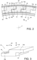
- each block 16 is made in one piece by two substantially parallelepipedal portions 16a, 16b offset from each other in the circumferential direction 28, as well as in the radial direction 30.
- the first portion 16a forms a radially external part of the block 16, connected and offset circumferentially from a second portion 16b forming the radially internal part of this same block.
- the first portion 16a of a first block covers, in the radial direction, at least partially the second portion 16b of a second block 16 directly consecutive in the circumferential direction 28, just as the second portion 16b of the first block is covered, in the radial direction, at least partially by the first portion 16a of a third block 16 directly consecutive in the circumferential direction 28, but arranged opposite the second.
- One of the particularities of the invention lies in the implementation of means for limiting/prohibiting the circumferential spacing between the adjacent blocks 16, and thus preventing the accumulation of such spacings from leading to neutron leaks of an unacceptable level between two directly consecutive blocks 16.
- several blocks 16 of the single annular row, and preferably all or almost all of them are each associated with two members locking means 32 intended to limit/prohibit its circumferential spacing, respectively in relation to each of the two blocks 16 located on either side of it in the circumferential direction 28.
- each locking member 32 located in the annular space 18, is integrated in a single piece into the first portion 16a of its associated first block 16.
- it could be integrated into the second portion 16b, without departing from the scope of the invention.
- this member 32 takes the form of a radial projection towards the inside extending in a long, linear manner in the longitudinal direction 8, that is to say locally orthogonally or substantially orthogonally to the circumferential direction 28.
- the long, linear projection 32 thus preferably extends continuously over the entire length of the associated first block 16, or only over a portion thereof.
- the projection 32 has a truncated disk shape, for example a half-disc, or any other shape such as a square, a rectangle, a trapezoid, etc.
- the projection 32 is housed in a recess 34 of complementary shape, open radially outwards and provided on the second portion 16b of a second block 16 directly adjacent to the first block in the circumferential direction 28. Due to the cooperation between the projection 32 and the recess 34, the first and second protection blocks 16 cannot move away from each other in the circumferential direction 28, or only over an amplitude limited by consumption of the circumferential clearance between these two parts 32, 34. Finally, it is noted that the cooperation between the projections 32 and the recesses 34 of the different blocks 16 is obtained as soon as each of the latter is introduced into the annular space 18, by relative sliding of each projection 32 in its associated recess 34, in the form of a gutter.
- the preferred embodiment which has just been described is also transposable to the case of a succession of protection blocks 16 in the longitudinal direction 8, in the annular space 18.
- This case is shown in the figure 4 , in which the locking members 32 are still in the form of radial projections, but here extending in a long, linear manner in the circumferential direction 28, just like the recesses 34 in which these projections 32 are inserted.
- FIG 5 represents an alternative to the solution proposed on the figure 4 .
- the locking member 32 forms a longitudinal end of the first portion 16a of the block 16, still projecting radially inwards.
- the hollow 34 of the protective block 16 is formed between on the one hand the junction between its two portions 16a, 16b, and on the other hand another projection 16' projecting radially outwards and constituting an opposite longitudinal end of this block 16, provided on the second portion 16b. Still in the context of a single row of protective elements 16, it is possible to provide that the mutual retention of these blocks 16 is carried out by locking members not integrated into these blocks, but distinct and cooperating with the latter.
- FIG. 6 A preferred embodiment in this sense is shown in the figure 6 , in which the blocks 16 always adopt the same general shape with their two portions 16a, 16b.
- the locking members 32 take the form of clips or similar elements, each coupling two directly consecutive blocks 16 in the longitudinal direction 8 to limit/prohibit their relative spacing in this same direction within the annular space 18.
- Each clip 32 thus has two legs respectively housed in two hollows 34 of the first and second protection blocks 16 which it connects.
- the central body of each clip 32 extends in the circumferential direction 28, and its legs arranged at the ends of this body project radially to be housed in the corresponding hollows 34 of the blocks 16.
- the staples 32 are arranged at the longitudinal junctions between the blocks 16, being placed on the external periphery of the annular row of blocks, between the latter and the external casing 22.
- the staples 32 could be placed on the internal periphery of the annular row, between the blocks and the internal shell 20.
- This staple system could also be implemented in a similar manner to limit/prohibit the relative spacing between the blocks 16 in the circumferential direction 28, without departing from the scope of the invention.
- each block 16 has a curvature in the circumferential direction 28 to follow the general shape of the annular space 18 in which it is located.
- each locking member 32 In all the embodiments envisaged with locking members 32 distinct from the protection blocks 16 which they connect, these members 32 each constitute a part of smaller dimensions than that of the blocks 16. Moreover, each locking member 32 only extends over a portion of the radial thickness E1 of the annular space 18, for example over 5 to 30% of this thickness.
- the locking members 32 are preferably made of a material different from that of the blocks 16, for example a metallic material.
- protection device 14 comprises two or more concentric annular rows of protection blocks 16, centered on the axis 2.
- each block 16 extends over all or part of the length of the lateral body 10 of the packaging, in the direction 8. It has a simple shape, for example generally parallelepiped, with possibly a curvature in the circumferential direction 28 to follow the general shape of the annular space 18 in which it is located.
- each block 16 of each of the two rows 36a, 36b is preferably made in a single piece, comprising a first portion 16a as well as a second portion 16b located in the circumferential extension of the first portion 16a.
- each block 16 of the first row 36a has its first portion 16a covered by the second portion 16b of one of the blocks of the second row 36b, just as its second portion 16b is covered by the first portion 16a of the directly consecutive block within the second row 36b.
- each block 16 of the second row 36b the first portion 16a of which is covered by the second portion 16b of one of the blocks of the first row 36a, and the second portion 16b of which is covered by the first portion 16a of the directly consecutive block within the first row 36a.
- a circumferential offset can be observed between two blocks 16 belonging respectively to the two rows 36a, 36b, and which partially overlap each other.
- first portion 16a of a first block 16 of the second row 36b is covered, in the radial direction 30, by the second portion 16b of a second block 16 of the first row 36a, and the second portion 16b of this first block is covered, still in the radial direction 30, by the first portion 16a of a third block 16 of the first row 36a, the second and third blocks 16 being directly consecutive in the circumferential direction 28 within the first row 36a.
- first portion 16a of a first block 16 of the first row 36a is covered, in the radial direction 30, by the second portion 16b of a second block 16 of the second row 36b, and the second portion 16b of this first block is covered, still in the radial direction 30, by the first portion 16a of a third block 16 of the second row 36b, the second and third blocks 16 being directly consecutive in the circumferential direction 28 within the second row 36b.
- first portion 16a of a first block 16 of the first row 36a is covered, in the radial direction 30, by the second portion 16b of a second block 16 of the second row 36b, and the second and third blocks 16 being directly consecutive in the circumferential direction 28 within the second row 36b.
- each protection block 16 of the second row 36b comprises two locking members 32 spaced circumferentially from each other, the first being located in the first portion 16a, and the second being located in the second portion 16b.
- each protection block 16 of the first row 36a comprises two recesses 34 spaced circumferentially from each other, the first being located in the first portion 16a, and the second being located in the second portion 16b.
- each protection block 16 of the second row 36b has its first locking member 32 inserted in the second recess 34 of a block 16 of the first row 16a, while its second locking member 32 is inserted in the first recess 34 of the block 16 directly consecutive within the first row 16a.
- the locking member 32 is located at the level of a radial overlap zone of the two blocks 16 which it helps to retain relative to each other, thus making it possible to limit/prohibit the relative gap between these same two blocks in the circumferential direction 28.
- the radially projecting locking members 32 are identical or similar to those described with reference to the figure 2 , namely in particular of a half-disc shaped cross-section. However, all the other features described with reference to the figure 2 are also applicable, such as the elongated character of the organs 32 in the longitudinal direction 8, etc.
- the radially projecting locking members 32 may be trapezoidal in shape, as may the recesses 34 with which they cooperate.
- the two concentric annular rows 36a, 36b are made of blocks 16 each with a generally U-shaped cross section.
- the second row 36b comprises U-shaped blocks 16 whose two opposite branches project radially outwards, while the first row 36a comprises U-shaped blocks 16 whose two opposite branches project radially inwards.
- the two branches of each block 16 of the second row 36b respectively form the two locking members 32 of this block, while the space 40 defined between the two branches of each block 16 of the first row 36a forms two adjacent hollows 34 merging circumferentially into each other, and intended to receive two branches/members 32 belonging respectively to two directly consecutive blocks 16 of the second row 36b.
- the two adjacent locking members 32, belonging to two separate blocks 16, together have a shape complementary to that of the space 40 in which these two members are inserted.
- the projecting members are replaced by radially oriented pins 32 whose two opposite ends are housed in two recesses 34 belonging respectively to two blocks 16, one of which belongs to the first row 36a, and the other of which belongs to the second row 36b.
- the pin(s) 32 may be replaced by a key extending in this same longitudinal direction 8, with its two opposite edges housed in two recesses 34 each in the form of a longitudinal groove.
Landscapes
- Physics & Mathematics (AREA)
- Engineering & Computer Science (AREA)
- General Engineering & Computer Science (AREA)
- High Energy & Nuclear Physics (AREA)
- Chemical & Material Sciences (AREA)
- Dispersion Chemistry (AREA)
- Buffer Packaging (AREA)
- Measurement Of Radiation (AREA)
Claims (15)
- Verpackung (1) zum Transportieren und/oder Lagern radioaktiver Materialien (3), umfassend einen Hohlraum zum Aufnehmen (12) radioaktiver Materialien sowie eine Strahlenschutzvorrichtung (14), die um den Aufnahmehohlraum herum in einem ringförmigen Raum (18) angeordnet ist, der auf einer Längsmittelachse (2) der Verpackung zentriert ist, wobei die Strahlenschutzvorrichtung (14) Strahlenschutzelemente (16) umfasst, die im ringförmigen Raum (18) angeordnet sind,
dadurch gekennzeichnet, dass mindestens zwei aufeinanderfolgenden Strahlenschutzelementen (16) in einer vorgegebenen Richtung des ringförmigen Raums zugeordnet, darunter eine Längsrichtung (8) und eine Umfangsrichtung (28) des Raums (18), in dem Raum ein Verriegelungselement (32) vorgesehen ist, das dazu ausgelegt ist, die Beabstandung der beiden Strahlenschutzelemente (16) im Verhältnis zueinander in der vorgegebenen Richtung zu begrenzen/zu verhindern, wobei das Verriegelungselement (32) mit einem ersten Element (16) von den beiden Strahlenschutzelementen zusammenwirkt oder in dieses integriert ist und mit einer Vertiefung (34) zusammenwirkt, die an einem zweiten Element (16) von den beiden Strahlenschutzelementen ausgebildet ist. - Verpackung nach Anspruch 1, dadurch gekennzeichnet, dass das Verriegelungselement (32) als ein einziges Bauteil im ersten Strahlenschutzelement (16) integriert ist.
- Verpackung nach Anspruch 2, dadurch gekennzeichnet, dass das Verriegelungselement (32) ein längliches Element ist, vorzugsweise mit einem Querschnitt in einer scheibenstumpfförmigen, quadratischen oder trapezförmigen Form.
- Verpackung nach Anspruch 3, dadurch gekennzeichnet, dass sich das längliche Verriegelungselement (32) orthogonal oder im Wesentlichen orthogonal zu der vorgegebenen Richtung erstreckt.
- Verpackung nach Anspruch 1, dadurch gekennzeichnet, dass das Verriegelungselement (32) ein von dem ersten und dem zweiten Strahlenschutzelement (16) getrenntes Bauteil ist und dass das Verriegelungselement (32) auch mit einer Vertiefung (34) zusammenwirkt, die am ersten Strahlenschutzelement (16) ausgebildet ist.
- Verpackung nach Anspruch 5, dadurch gekennzeichnet, dass das Verriegelungselement (32) ein Bauteil mit einer kleineren Abmessung als die des ersten und des zweiten Strahlenschutzelements (16) ist und vorzugsweise aus einem anderen Material hergestellt ist.
- Verpackung nach Anspruch 5 oder 6, dadurch gekennzeichnet, dass das Verriegelungselement (32) ein Stift, ein Keil oder eine Klammer ist.
- Verpackung nach einem der Ansprüche 5 bis 7, dadurch gekennzeichnet, dass sich das Verriegelungselement (32) nur an einem Teil der radialen Dicke (E1) des ringförmigen Raums (18) erstreckt.
- Verpackung nach einem der vorhergehenden Ansprüche, dadurch gekennzeichnet, dass das erste und das zweite Strahlenschutzelement (16) in der vorgegebenen Richtung in derselben ringförmigen Reihe von Strahlenschutzelementen (16) direkt aufeinander folgen.
- Verpackung nach einem der Ansprüche 1 bis 8, dadurch gekennzeichnet, dass das erste und das zweite Strahlenschutzelement (16) jeweils zu zwei konzentrischen ringförmigen Reihen (36a, 36b) von Strahlenschutzelementen (16) gehören, wobei das erste und das zweite Strahlenschutzelement (16) somit in Umfangsrichtung relativ zueinander versetzt sind und sich in einer radialen Richtung (30) des ringförmigen Raums (18) teilweise überlappen.
- Verpackung nach Anspruch 10, dadurch gekennzeichnet, dass das Verriegelungselement (32) sich auf Höhe eines radialen Überlappungsbereichs des ersten und des zweiten Strahlenschutzelement (16) befindet.
- Verpackung nach einem der vorhergehenden Ansprüche, dadurch gekennzeichnet, dass der ringförmige Raum (18) durch eine innere Hülse (20) und ein äußeres Gehäuse (22) definiert ist.
- Gehäuse nach Anspruch 12, dadurch gekennzeichnet, dass der ringförmige Raum (18) frei von Wärmeleitern ist, die die innere Hülse (20) mit dem äußeren Gehäuse (22) verbinden.
- Verpackung nach einem der vorhergehenden Ansprüche, dadurch gekennzeichnet, dass die Strahlenschutzelemente (16) Neutronenschutzelemente, vorzugsweise Gussharzblöcke, sind.
- Verpackung nach einem der vorhergehenden Ansprüche, dadurch gekennzeichnet, dass mindestens einem Strahlenschutzelement (16) der Strahlenschutzvorrichtung (14) und vorzugsweise mehreren der Elemente oder sogar jedem davon zwei Verriegelungselemente (32) zugeordnet sind, die dazu ausgelegt sind, deren Beabstandung in der vorgegebene Richtung jeweils im Verhältnis zu jedem der beiden Strahlenschutzelemente (16), die sich auf beiden Seiten davon in derselben vorgegebenen Richtung befinden, zu begrenzen/verhindern.
Applications Claiming Priority (1)
| Application Number | Priority Date | Filing Date | Title |
|---|---|---|---|
| FR2010235A FR3114907B1 (fr) | 2020-10-07 | 2020-10-07 | Emballage pour le transport et/ou le stockage de matieres radioactives, comprenant un dispositif de protection radiologique reduisant les risques de fuites radiologiques |
Publications (2)
| Publication Number | Publication Date |
|---|---|
| EP3982375A1 EP3982375A1 (de) | 2022-04-13 |
| EP3982375B1 true EP3982375B1 (de) | 2024-11-06 |
Family
ID=74758883
Family Applications (1)
| Application Number | Title | Priority Date | Filing Date |
|---|---|---|---|
| EP21306304.3A Active EP3982375B1 (de) | 2020-10-07 | 2021-09-21 | Verpackung für den transport und/oder die lagerung von radioaktivem material, die eine strahlenschutzvorrichtung umfasst, die die risiken eines strahlungsaustritts reduziert |
Country Status (8)
| Country | Link |
|---|---|
| US (1) | US11715576B2 (de) |
| EP (1) | EP3982375B1 (de) |
| JP (1) | JP7773335B2 (de) |
| KR (1) | KR20220046485A (de) |
| CN (1) | CN114300171B (de) |
| ES (1) | ES3002185T3 (de) |
| FI (1) | FI3982375T3 (de) |
| FR (1) | FR3114907B1 (de) |
Families Citing this family (2)
| Publication number | Priority date | Publication date | Assignee | Title |
|---|---|---|---|---|
| FR3143175B1 (fr) | 2022-12-09 | 2025-07-18 | Orano Nuclear Packages And Services | Emballage pour le transport et/ou l’entreposage de matieres radioactives, comprenant un dispositif de protection radiologique simplifiee, reduisant les risques de fuites radiologiques |
| DE102023200244A1 (de) * | 2023-01-13 | 2024-07-18 | Forschungszentrum Jülich GmbH | Vorrichtung zur Abschirmung und Montageverfahren |
Citations (6)
| Publication number | Priority date | Publication date | Assignee | Title |
|---|---|---|---|---|
| DE1847142U (de) | 1961-11-23 | 1962-02-22 | Hutterer & Lechner Kg | Ziegel aus blei, schwerbeton oder sonstigem strahlenhemmenden material. |
| FR1323585A (fr) | 1962-02-22 | 1963-04-12 | Commissariat Energie Atomique | éléments de protection et ensemble tel que château formé par ces éléments ou d'autres analogues |
| US3774037A (en) | 1971-05-24 | 1973-11-20 | Nl Industries Inc | Radiation shielding means joint |
| JPS58193496A (ja) | 1982-05-07 | 1983-11-11 | 三菱原子力工業株式会社 | 組立式放射線遮蔽体 |
| JP2004138544A (ja) | 2002-10-18 | 2004-05-13 | Mitsubishi Heavy Ind Ltd | 放射性物質収納容器 |
| US20120007004A1 (en) | 2009-11-10 | 2012-01-12 | Tn International | Canister for transporting and/or storing radioactive materials comprising radially stacked radiological protection components |
Family Cites Families (12)
| Publication number | Priority date | Publication date | Assignee | Title |
|---|---|---|---|---|
| DE2108855A1 (en) * | 1970-05-11 | 1971-11-25 | Dampferzeugerbau Veb K | Canister for atomic wastes |
| FR2776118B1 (fr) * | 1998-03-13 | 2000-06-09 | Transnucleaire | Dispositif de protection contre les rayonnements pour conteneur de transport de matieres radioactives |
| JP3411911B2 (ja) * | 2001-03-29 | 2003-06-03 | 三菱重工業株式会社 | 使用済み燃料収納用角パイプ、バスケットおよび使用済み燃料収納容器 |
| KR100790661B1 (ko) * | 2004-08-10 | 2008-01-02 | 미츠비시 쥬고교 가부시키가이샤 | 캐스크용 완충체 |
| FR2914104B1 (fr) * | 2007-03-21 | 2012-05-04 | Tn Int | Emballage pour le transport et/ou stockage de matieres nucleaires comprenant une protection radiologique en plomb coule sur une armature metallique |
| US7973298B2 (en) * | 2007-10-10 | 2011-07-05 | Kobe Steel, Ltd. | Transport/storage cask for radioactive material |
| JP5030814B2 (ja) * | 2008-02-22 | 2012-09-19 | 三菱重工業株式会社 | キャスク用緩衝体 |
| JP2010008224A (ja) * | 2008-06-26 | 2010-01-14 | Kyushu Electric Power Co Inc | 放射線遮蔽容器 |
| FR3010226B1 (fr) * | 2013-09-05 | 2017-12-29 | Tn Int | Colis comprenant des moyens ameliores d'amortissement de choc entre un ensemble renfermant des matieres radioactives et le couvercle de l'emballage |
| CN107615398B (zh) * | 2016-03-22 | 2019-11-05 | 霍尔泰克国际公司 | 用于存储及/或运输放射性材料的装置 |
| FR3060192B1 (fr) * | 2016-12-09 | 2019-05-17 | Tn International | Emballage de transport et/ou d'entreposage de matieres radioactives comprenant un systeme de communication fluidique ameliore entre l'interieur et l'exterieur de l'enceinte de confinement |
| WO2021202882A1 (en) * | 2020-04-01 | 2021-10-07 | Holtec International | Storage system for radioactive nuclear waste with pressure surge protection |
-
2020
- 2020-10-07 FR FR2010235A patent/FR3114907B1/fr active Active
-
2021
- 2021-09-21 FI FIEP21306304.3T patent/FI3982375T3/fi active
- 2021-09-21 ES ES21306304T patent/ES3002185T3/es active Active
- 2021-09-21 EP EP21306304.3A patent/EP3982375B1/de active Active
- 2021-10-04 US US17/492,900 patent/US11715576B2/en active Active
- 2021-10-06 JP JP2021164804A patent/JP7773335B2/ja active Active
- 2021-10-06 KR KR1020210132028A patent/KR20220046485A/ko active Pending
- 2021-10-08 CN CN202111173138.8A patent/CN114300171B/zh active Active
Patent Citations (6)
| Publication number | Priority date | Publication date | Assignee | Title |
|---|---|---|---|---|
| DE1847142U (de) | 1961-11-23 | 1962-02-22 | Hutterer & Lechner Kg | Ziegel aus blei, schwerbeton oder sonstigem strahlenhemmenden material. |
| FR1323585A (fr) | 1962-02-22 | 1963-04-12 | Commissariat Energie Atomique | éléments de protection et ensemble tel que château formé par ces éléments ou d'autres analogues |
| US3774037A (en) | 1971-05-24 | 1973-11-20 | Nl Industries Inc | Radiation shielding means joint |
| JPS58193496A (ja) | 1982-05-07 | 1983-11-11 | 三菱原子力工業株式会社 | 組立式放射線遮蔽体 |
| JP2004138544A (ja) | 2002-10-18 | 2004-05-13 | Mitsubishi Heavy Ind Ltd | 放射性物質収納容器 |
| US20120007004A1 (en) | 2009-11-10 | 2012-01-12 | Tn International | Canister for transporting and/or storing radioactive materials comprising radially stacked radiological protection components |
Also Published As
| Publication number | Publication date |
|---|---|
| ES3002185T3 (en) | 2025-03-06 |
| JP2022061971A (ja) | 2022-04-19 |
| KR20220046485A (ko) | 2022-04-14 |
| US11715576B2 (en) | 2023-08-01 |
| FR3114907A1 (fr) | 2022-04-08 |
| FR3114907B1 (fr) | 2022-12-23 |
| CN114300171A (zh) | 2022-04-08 |
| US20220108811A1 (en) | 2022-04-07 |
| EP3982375A1 (de) | 2022-04-13 |
| CN114300171B (zh) | 2026-01-02 |
| JP7773335B2 (ja) | 2025-11-19 |
| FI3982375T3 (fi) | 2025-02-12 |
Similar Documents
| Publication | Publication Date | Title |
|---|---|---|
| EP2140459B1 (de) | Container zum transportieren und/oder lagern von kernmaterialien mit einer aus auf eine metallverstärkung gegossenem blei hergestellten radiologischen abschirmung | |
| EP2308059B1 (de) | Lagergestell für frische oder verbrauchte kernbrennstoffbaugruppen | |
| EP3000113B1 (de) | Lagerbehälter für bestrahlten brennstoff mit führungsschienen mit einem stossdämpfenden gehäuse | |
| EP3982375A1 (de) | Verpackung für den transport und/oder die lagerung von radioaktivem material, die eine strahlenschutzvorrichtung umfasst, die die risiken eines strahlungsaustritts reduziert | |
| EP2320429B1 (de) | Verpackung für den Transport und/oder zur Zwischenlagerung radioaktiver Stoffe, die radial geschichtete Strahlenschutzelemente umfasst | |
| FR2557612A1 (fr) | Chambre de detonation pour essais d'explosifs | |
| FR2625928A1 (fr) | Plaque obturatrice pour fermeture a coulisse d'un recipient metallurgique, et fermeture a coulisse comportant de telles plaques | |
| EP1926107B1 (de) | Verstauungsvorrichtung zur Lagerung und/oder zum Transport von Kernbrennelementen | |
| FR3054922A1 (fr) | Panier de rangement pour matieres radioactives, presentant un encombrement optimise | |
| EP3363022A1 (de) | Kühlelement mit sockel für wärmeabfuhr aus einer packung | |
| EP3766082B1 (de) | Verpackung zum transport und/oder lagern von radioaktiven materialien, die eine einfachere herstellung und verbesserte wärmeleitfähigkeit ermöglicht | |
| FR2756328A1 (fr) | Barriere thermique de pompe primaire | |
| FR3143175A1 (fr) | Emballage pour le transport et/ou l’entreposage de matieres radioactives, comprenant un dispositif de protection radiologique simplifiee, reduisant les risques de fuites radiologiques | |
| EP3743928B1 (de) | Lagerkorb für radioaktive materialien mit optimiertem platzbedarf und mit gehäusen mit genauerer geometrie | |
| BE897370A (fr) | Element combustible de reacteur nucleaire, | |
| FR3049756A1 (fr) | Emballage de transport et/ou d'entreposage de matieres radioactives equipe de dispositifs de dissipation de chaleur realises d'un seul tenant | |
| EP4315369B1 (de) | Vorrichtung zum transport von uranhexafluorid mit stossdämpfern | |
| FR3076057A1 (fr) | Emballage de transport et/ou d'entreposage de matieres radioactives presentant des moyens ameliores de maintien de capot amortisseur | |
| FR2872956A1 (fr) | Dispositif externe d'evacuation de chaleur pour emballage destine au stockage et/ou au transport de matieres nucleaires | |
| EP3782168B1 (de) | Behälter für den transport und/oder die lagerung von radioaktivem material mit vorrichtung zum erleichtern der handhabung des radioaktiven materiales | |
| FR3060192A1 (fr) | Emballage de transport et/ou d'entreposage de matieres radioactives comprenant un systeme de communication fluidique ameliore entre l'interieur et l'exterieur de l'enceinte de confinement | |
| WO2004105048A2 (fr) | Dispositif de rangement pour le transport/stockage d'assemblages de combustible nucleaire | |
| FR3160046A1 (fr) | Emballage de transport et/ou d’entreposage de matiéres radioactives présentant une conception améliorée limitant les risques de contamination de ses éléments constituants | |
| WO2022038325A1 (fr) | Ensemble pour le transport d'hexafluorure d'uranium |
Legal Events
| Date | Code | Title | Description |
|---|---|---|---|
| PUAI | Public reference made under article 153(3) epc to a published international application that has entered the european phase |
Free format text: ORIGINAL CODE: 0009012 |
|
| STAA | Information on the status of an ep patent application or granted ep patent |
Free format text: STATUS: REQUEST FOR EXAMINATION WAS MADE |
|
| 17P | Request for examination filed |
Effective date: 20210921 |
|
| AK | Designated contracting states |
Kind code of ref document: A1 Designated state(s): AL AT BE BG CH CY CZ DE DK EE ES FI FR GB GR HR HU IE IS IT LI LT LU LV MC MK MT NL NO PL PT RO RS SE SI SK SM TR |
|
| P01 | Opt-out of the competence of the unified patent court (upc) registered |
Effective date: 20230526 |
|
| GRAP | Despatch of communication of intention to grant a patent |
Free format text: ORIGINAL CODE: EPIDOSNIGR1 |
|
| STAA | Information on the status of an ep patent application or granted ep patent |
Free format text: STATUS: GRANT OF PATENT IS INTENDED |
|
| INTG | Intention to grant announced |
Effective date: 20240731 |
|
| GRAS | Grant fee paid |
Free format text: ORIGINAL CODE: EPIDOSNIGR3 |
|
| GRAA | (expected) grant |
Free format text: ORIGINAL CODE: 0009210 |
|
| STAA | Information on the status of an ep patent application or granted ep patent |
Free format text: STATUS: THE PATENT HAS BEEN GRANTED |
|
| AK | Designated contracting states |
Kind code of ref document: B1 Designated state(s): AL AT BE BG CH CY CZ DE DK EE ES FI FR GB GR HR HU IE IS IT LI LT LU LV MC MK MT NL NO PL PT RO RS SE SI SK SM TR |
|
| REG | Reference to a national code |
Ref country code: GB Ref legal event code: FG4D Free format text: NOT ENGLISH |
|
| REG | Reference to a national code |
Ref country code: CH Ref legal event code: EP |
|
| REG | Reference to a national code |
Ref country code: DE Ref legal event code: R096 Ref document number: 602021021358 Country of ref document: DE |
|
| REG | Reference to a national code |
Ref country code: IE Ref legal event code: FG4D Free format text: LANGUAGE OF EP DOCUMENT: FRENCH |
|
| REG | Reference to a national code |
Ref country code: NL Ref legal event code: FP |
|
| REG | Reference to a national code |
Ref country code: SE Ref legal event code: TRGR |
|
| REG | Reference to a national code |
Ref country code: FI Ref legal event code: FGE |
|
| REG | Reference to a national code |
Ref country code: ES Ref legal event code: FG2A Ref document number: 3002185 Country of ref document: ES Kind code of ref document: T3 Effective date: 20250306 |
|
| REG | Reference to a national code |
Ref country code: LT Ref legal event code: MG9D |
|
| PG25 | Lapsed in a contracting state [announced via postgrant information from national office to epo] |
Ref country code: PT Free format text: LAPSE BECAUSE OF FAILURE TO SUBMIT A TRANSLATION OF THE DESCRIPTION OR TO PAY THE FEE WITHIN THE PRESCRIBED TIME-LIMIT Effective date: 20250306 Ref country code: HR Free format text: LAPSE BECAUSE OF FAILURE TO SUBMIT A TRANSLATION OF THE DESCRIPTION OR TO PAY THE FEE WITHIN THE PRESCRIBED TIME-LIMIT Effective date: 20241106 Ref country code: IS Free format text: LAPSE BECAUSE OF FAILURE TO SUBMIT A TRANSLATION OF THE DESCRIPTION OR TO PAY THE FEE WITHIN THE PRESCRIBED TIME-LIMIT Effective date: 20250306 |
|
| REG | Reference to a national code |
Ref country code: AT Ref legal event code: MK05 Ref document number: 1740331 Country of ref document: AT Kind code of ref document: T Effective date: 20241106 |
|
| PG25 | Lapsed in a contracting state [announced via postgrant information from national office to epo] |
Ref country code: BG Free format text: LAPSE BECAUSE OF FAILURE TO SUBMIT A TRANSLATION OF THE DESCRIPTION OR TO PAY THE FEE WITHIN THE PRESCRIBED TIME-LIMIT Effective date: 20241106 |
|
| PG25 | Lapsed in a contracting state [announced via postgrant information from national office to epo] |
Ref country code: NO Free format text: LAPSE BECAUSE OF FAILURE TO SUBMIT A TRANSLATION OF THE DESCRIPTION OR TO PAY THE FEE WITHIN THE PRESCRIBED TIME-LIMIT Effective date: 20250206 |
|
| PG25 | Lapsed in a contracting state [announced via postgrant information from national office to epo] |
Ref country code: LV Free format text: LAPSE BECAUSE OF FAILURE TO SUBMIT A TRANSLATION OF THE DESCRIPTION OR TO PAY THE FEE WITHIN THE PRESCRIBED TIME-LIMIT Effective date: 20241106 Ref country code: GR Free format text: LAPSE BECAUSE OF FAILURE TO SUBMIT A TRANSLATION OF THE DESCRIPTION OR TO PAY THE FEE WITHIN THE PRESCRIBED TIME-LIMIT Effective date: 20250207 Ref country code: AT Free format text: LAPSE BECAUSE OF FAILURE TO SUBMIT A TRANSLATION OF THE DESCRIPTION OR TO PAY THE FEE WITHIN THE PRESCRIBED TIME-LIMIT Effective date: 20241106 |
|
| PG25 | Lapsed in a contracting state [announced via postgrant information from national office to epo] |
Ref country code: PL Free format text: LAPSE BECAUSE OF FAILURE TO SUBMIT A TRANSLATION OF THE DESCRIPTION OR TO PAY THE FEE WITHIN THE PRESCRIBED TIME-LIMIT Effective date: 20241106 |
|
| PG25 | Lapsed in a contracting state [announced via postgrant information from national office to epo] |
Ref country code: RS Free format text: LAPSE BECAUSE OF FAILURE TO SUBMIT A TRANSLATION OF THE DESCRIPTION OR TO PAY THE FEE WITHIN THE PRESCRIBED TIME-LIMIT Effective date: 20250206 |
|
| PG25 | Lapsed in a contracting state [announced via postgrant information from national office to epo] |
Ref country code: SM Free format text: LAPSE BECAUSE OF FAILURE TO SUBMIT A TRANSLATION OF THE DESCRIPTION OR TO PAY THE FEE WITHIN THE PRESCRIBED TIME-LIMIT Effective date: 20241106 |
|
| PG25 | Lapsed in a contracting state [announced via postgrant information from national office to epo] |
Ref country code: DK Free format text: LAPSE BECAUSE OF FAILURE TO SUBMIT A TRANSLATION OF THE DESCRIPTION OR TO PAY THE FEE WITHIN THE PRESCRIBED TIME-LIMIT Effective date: 20241106 |
|
| PG25 | Lapsed in a contracting state [announced via postgrant information from national office to epo] |
Ref country code: EE Free format text: LAPSE BECAUSE OF FAILURE TO SUBMIT A TRANSLATION OF THE DESCRIPTION OR TO PAY THE FEE WITHIN THE PRESCRIBED TIME-LIMIT Effective date: 20241106 |
|
| PG25 | Lapsed in a contracting state [announced via postgrant information from national office to epo] |
Ref country code: RO Free format text: LAPSE BECAUSE OF FAILURE TO SUBMIT A TRANSLATION OF THE DESCRIPTION OR TO PAY THE FEE WITHIN THE PRESCRIBED TIME-LIMIT Effective date: 20241106 |
|
| PG25 | Lapsed in a contracting state [announced via postgrant information from national office to epo] |
Ref country code: SK Free format text: LAPSE BECAUSE OF FAILURE TO SUBMIT A TRANSLATION OF THE DESCRIPTION OR TO PAY THE FEE WITHIN THE PRESCRIBED TIME-LIMIT Effective date: 20241106 |
|
| REG | Reference to a national code |
Ref country code: DE Ref legal event code: R026 Ref document number: 602021021358 Country of ref document: DE |
|
| PLBI | Opposition filed |
Free format text: ORIGINAL CODE: 0009260 |
|
| PLAX | Notice of opposition and request to file observation + time limit sent |
Free format text: ORIGINAL CODE: EPIDOSNOBS2 |
|
| 26 | Opposition filed |
Opponent name: GNS GESELLSCHAFT FUER NUKLEAR-SERVICE MBH Effective date: 20250804 |
|
| REG | Reference to a national code |
Ref country code: CH Ref legal event code: U11 Free format text: ST27 STATUS EVENT CODE: U-0-0-U10-U11 (AS PROVIDED BY THE NATIONAL OFFICE) Effective date: 20251002 |
|
| PGFP | Annual fee paid to national office [announced via postgrant information from national office to epo] |
Ref country code: FI Payment date: 20250929 Year of fee payment: 5 |
|
| PGFP | Annual fee paid to national office [announced via postgrant information from national office to epo] |
Ref country code: DE Payment date: 20250926 Year of fee payment: 5 |
|
| PGFP | Annual fee paid to national office [announced via postgrant information from national office to epo] |
Ref country code: NL Payment date: 20250926 Year of fee payment: 5 |
|
| PGFP | Annual fee paid to national office [announced via postgrant information from national office to epo] |
Ref country code: GB Payment date: 20250929 Year of fee payment: 5 Ref country code: BE Payment date: 20250929 Year of fee payment: 5 |
|
| PGFP | Annual fee paid to national office [announced via postgrant information from national office to epo] |
Ref country code: FR Payment date: 20250929 Year of fee payment: 5 |
|
| PGFP | Annual fee paid to national office [announced via postgrant information from national office to epo] |
Ref country code: CZ Payment date: 20250911 Year of fee payment: 5 |
|
| PLBB | Reply of patent proprietor to notice(s) of opposition received |
Free format text: ORIGINAL CODE: EPIDOSNOBS3 |
|
| PGFP | Annual fee paid to national office [announced via postgrant information from national office to epo] |
Ref country code: IT Payment date: 20250926 Year of fee payment: 5 |
|
| PGFP | Annual fee paid to national office [announced via postgrant information from national office to epo] |
Ref country code: SE Payment date: 20250930 Year of fee payment: 5 Ref country code: CH Payment date: 20251002 Year of fee payment: 5 |
|
| PGFP | Annual fee paid to national office [announced via postgrant information from national office to epo] |
Ref country code: ES Payment date: 20251010 Year of fee payment: 5 |