EP3977039B1 - Detonationsenergieabsorbtionsvorrichtung und damit ausgestattetes fahrzeug - Google Patents
Detonationsenergieabsorbtionsvorrichtung und damit ausgestattetes fahrzeug Download PDFInfo
- Publication number
- EP3977039B1 EP3977039B1 EP20724059.9A EP20724059A EP3977039B1 EP 3977039 B1 EP3977039 B1 EP 3977039B1 EP 20724059 A EP20724059 A EP 20724059A EP 3977039 B1 EP3977039 B1 EP 3977039B1
- Authority
- EP
- European Patent Office
- Prior art keywords
- vehicle
- energy absorption
- absorption device
- deformation
- securing element
- Prior art date
- Legal status (The legal status is an assumption and is not a legal conclusion. Google has not performed a legal analysis and makes no representation as to the accuracy of the status listed.)
- Active
Links
Images


Classifications
-
- F—MECHANICAL ENGINEERING; LIGHTING; HEATING; WEAPONS; BLASTING
- F41—WEAPONS
- F41H—ARMOUR; ARMOURED TURRETS; ARMOURED OR ARMED VEHICLES; MEANS OF ATTACK OR DEFENCE, e.g. CAMOUFLAGE, IN GENERAL
- F41H7/00—Armoured or armed vehicles
- F41H7/02—Land vehicles with enclosing armour, e.g. tanks
- F41H7/04—Armour construction
- F41H7/046—Shock resilient mounted seats for armoured or fighting vehicles
Definitions
- the invention relates to an energy absorption device for protecting a vehicle element, in particular a vehicle element of a military vehicle, from a detonation effect, comprising a first fastening element which can be connected to a vehicle chassis or a vehicle tub and a second fastening element which can be connected to the vehicle element to be protected, wherein At least two webs are arranged between the first and the second fastening element.
- the application relates to a vehicle with such an energy absorption device.
- a cabin for a construction vehicle which has at least one hydraulically damped rubber bearing means and at least one roll stabilizing means in the rear area of the cabin. This results in improved spring comfort in the cabin during faster transport journeys.
- the suspensions of construction machinery cabins pursue completely different objectives - they do not offer any protection against detonations - than the suspensions of military vehicles, so they are not comparable.
- the FR 2 901 750 already describes a device for protecting a vehicle seat against detonations according to the generic term.
- the invention is based on the object of creating an energy absorption device for a vehicle, in particular a military vehicle, which is small in size and solves this conflict of objectives.
- an energy absorption device for protecting a vehicle element, in particular a military vehicle, from a detonation effect.
- the energy absorption device includes a first fastening element that is connectable to a vehicle chassis or a vehicle tub and a second fastening element that is connectable to the vehicle element to be protected.
- At least two webs are arranged between the first and second fastening elements. The at least two webs are arranged in such a way that they lie one above the other in a common plane.
- a vehicle in particular a military vehicle, comprising such an energy absorption device or as described below and a vehicle element, the vehicle element being connected to the vehicle via the energy absorption device.
- the vehicle can be, for example, a wheeled or tracked vehicle.
- the tracked vehicle can be, for example, a recovery vehicle, an engineer tank, a mine clearing vehicle, an armored personnel carrier or a main battle tank.
- the wheeled vehicle can be, for example, a heavy truck, a tractor-trailer, a crane or a wheeled tank.
- the energy absorption device creates a small-sized energy absorption device which, on the one hand, provides elastic support for the vehicle element that can be connected to it and, at the same time, can absorb high energy in the form of deformation work in the event of a detonation.
- the vehicle element that is connected to the energy absorption device can be, for example, a cabin or a shelter of a vehicle.
- the cabin can be a protected cabin.
- the vehicle element can be a structure, a platform, a floor, a vibrating floor, an intermediate floor, a floor plate or a component of one of the aforementioned elements.
- the vehicle element can be a base plate, a seat device, a weapon system, a device holder, a shelf or a component of one of the aforementioned elements.
- the energy absorption device protects the vehicle element from a detonation effect, such as can be caused, for example, by a mine or a booby trap.
- the energy absorption device according to the invention makes it possible for it to be plastically deformed in a controlled manner in the event of a detonation and for the vehicle element that can be connected to it not to be damaged.
- the webs have at least one deformation zone.
- the at least one deformation zone is a zone in which the webs deform plastically when they are deflected to a correspondingly strong extent. This happens due to the design of the energy absorption device, which requires that the webs first deform in the deformation zones.
- the webs in the deformation zones are weakened by the choice of material or geometry in such a way that they deform first in the deformation zones.
- first fastening element, the second fastening element, the at least two webs and the at least one deformation zone are arranged such that they lie one above the other in the plane that is perpendicular to the first and the second fastening element.
- the fastening elements and the webs of the energy absorption device are arranged in an accordion-like manner in a common plane, so that a small energy absorption device is created.
- the webs are designed to be flexible, so that the energy absorption device resiliently supports the vehicle element.
- flexurally stiffened transition zones are formed between the fastening devices and the respective adjacent webs.
- the webs of the energy absorption device do not simply bend or break off, but rather a defined deformation is achieved in the area of the transition deformation zones of the webs.
- transition deformation zones are formed adjacent to the flexurally stiffened transition zones.
- bend-stiffened, in particular substantially bend-resistant, corners are formed between the webs.
- the deformation zones are formed adjacent to the bending-stiffened corners.
- the deformation zones from the second fastening element towards the first fastening element are at least partially designed to be more difficult to deform than the previous deformation zones, so that the energy absorption device has a progressive deformation characteristic.
- the thickness of the webs increases from the second fastening element towards the first fastening element, so that the energy absorption device has a progressive spring characteristic.
- the spring characteristic can be degressive.
- the webs are arranged in a zigzag manner in an alternating direction.
- inner radii between the webs are formed in rigid corners and/or inner radii in the transition zones.
- notch stresses are specifically induced in the deformation zones.
- the notch stress that occurs can be influenced by the size of the radius of the inner radii, so that the size of the notch stress and also the limit at which the deformation occurs can be adjusted by the radius.
- the inner radii between the webs in rigid corners and/or the inner radii in the transition deformation zones from the second fastening element to the first fastening element become larger.
- the deformation sequence is set specifically so that a deformation from the second fastening element to the first fastening element occurs gradually.
- the inner radii between the webs in rigid corners and/or the inner radii in the transition zones from the first fastening element to the second fastening element to become larger. This ensures that the notch stresses within the deformation zones are highest directly on the second fastening element and the deformation occurs first in the vicinity of the vehicle element.
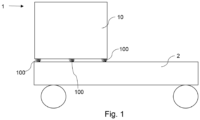
- Fig. 1 shows a first vehicle 1 according to the invention with a vehicle chassis 2.
- a vehicle element 10 is formed on the vehicle chassis 2.
- the vehicle 1 is preferably a military vehicle.
- the vehicle element 10 can be, for example, a cabin, a driver's cab, a platform, a structure or similar act.
- At least one energy absorption device 100 which supports the vehicle element 10 on the vehicle 1, is arranged between the vehicle element 10 and the vehicle chassis 2.
- the energy absorption device 100 serves to protect the vehicle element 10 from a detonation effect and is described in more detail in the 4a to 6 shown.
- the energy absorption device 100 according to 4a to 6 can be found in all vehicles Fig. 1 to 3 .
- Fig. 2 shows a second vehicle 1′ according to the invention, which essentially corresponds to the first vehicle 1, with the difference that the vehicle element 10′ is a floor or intermediate floor.
- the vehicle element 10′ is mounted on the vehicle chassis 2 of the vehicle 1 by means of at least one energy absorption device 100.
- the vehicle element 10' is arranged within a cabin or a driver's cab.
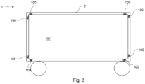
- Fig. 3 shows a third vehicle 1" according to the invention with a vehicle tub 2'.
- a vehicle element 10" is mounted within the vehicle tub 2' by means of at least one energy absorption device 100.
- the vehicle element 10" can be, for example, a vehicle interior or a protective space. Deviating from this Fig. 3
- the vehicle element 10" can also be a floor or intermediate floor.
- the vehicle element 10′′ is connected to the vehicle tub 2′ by several energy absorption devices 100 and is stored within it.
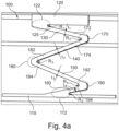
- Fig. 4a shows a schematic representation of an energy absorption device 100 according to the invention in a starting position, i.e. a position in which the energy absorption device 100 is not deformed.
- the energy absorption device 100 includes a first fastening element 110, which can be connected to the vehicle chassis 2 or the vehicle tub 2 'of the vehicle 1.
- the first fastening element 110 is designed as a plate or sheet metal and is connected to the vehicle chassis 2 or the vehicle tub 2 'in the installed state.
- the energy absorption device 100 includes a second fastening element 120, which can be connected to the vehicle element 10 to be protected.
- the second fastening element 110 is preferably also designed as a plate or sheet metal and is connected to the vehicle element 10 in the installed state.
- the wall thickness and the dimensions of the first fastening element 110 and the second fastening element 120 can be adapted to the geometry of the energy absorption device 100 in different ways. Like in the Fig. 1 shown, the first fastening element 110 can have a smaller wall thickness and be wider than the second fastening element 120.
- At least two webs 130, 140, 150, 160 are arranged between the first and second fastening elements 110, 120.
- four webs 130, 140, 150, 160 are shown.
- the first fastening element 110, the second fastening element 120, the webs 130, 140, 150, 160 and the deformation zones 172, 174, 182, 184, 192, 194 are arranged such that they are one above the other in a common plane E are arranged, the common plane E being perpendicular to the two fastening elements 110, 120.
- the webs 130, 140, 150, 160 are alternately arranged one above the other in a zigzag manner in different directions. In other words, the webs 130, 140, 150, 160 are arranged one above the other in an accordion-like manner.
- the webs 130, 140, 150, 160 are each designed to be flexible.
- the length of the webs 130, 140, 150, 160 can differ from one another, so that, for example, a first web 130 and a fourth web 160, which are connected to the fastening elements 110, 120, are shorter than a second web 140 and third web 150.
- the different lengths of the webs 130, 140, 150, 160 ensure that they can deflect elastically to different degrees and result in a defined bending pattern of the energy absorption device 100 in the event of an elastic deformation.
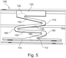
- a bending figure as a result of an elastic deformation is, for example, in Fig. 5 shown.
- Bending-stiffened corners 170, 180, 190 are formed between the webs 130, 140, 150, 160.
- the bend-stiffened corners 170, 180, 190 are designed in such a way that they essentially do not bend and ensure that when the webs 130, 140, 150, 160 are elastically deformed, the bend-stiffened corners 170, 180, 190 ensure that the Webs 130, 140, 150, 160 cannot be folded together due to deformation of the corners 170, 180, 190. This ensures that, in addition to elastic deformation in the event of a With greater deflection, plastic deformation of the deformation zones 172, 174, 182, 184, 192, 194 can take place.
- the webs 130, 140, 150, 160 each have at least one deformation zone 172, 174, 182, 184, 192, 194.
- the deformation zones 172, 174, 182, 184, 192, 194 are each formed adjacent to the bend-stiffened corners 170, 180, 190.
- flexurally stiffened transition zones 112, 122 are formed. These have a comparable effect to the bend-stiffened corners 170, 180, 190.
- transition deformation zones 115, 125 are formed adjacent to the flexurally stiffened transition zones 112, 122.
- inner radii R2, R3, R4 are formed between the webs 130, 140, 150, 160 in the deformation zones 172, 174, 182, 184, 192, 194 and/or inner radii R1, R5 in the transition zones 112, 122.
- Fig. 4a are the inner radii R2, R3, R4, which are formed between the webs 130, 140, 150, 160 in the rigid corners 170, 180, 190, increasing from the second fastening element 120 to the first fastening element 110.
- a fourth radius R4 between the third web 150 and fourth web 160 is largest.
- a third radius R3 between the second web 140 and the third web 150 is smaller than the fourth radius (R3 ⁇ R4).
- a second radius R2 between the first web 130 and the second web 140 is smaller than the third radius R3.
- the thickness t1, t2, t3, t4 of the webs 130, 140, 150, 160 can be made larger from the second fastening element 120 towards the first fastening element 110, so that the energy absorption device 100 has a progressive spring characteristic.
- the following mathematical relationship applies to the thicknesses t1 to t4: t1 ⁇ t2 ⁇ t3 ⁇ t4.
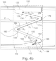
- Fig. 4b clearly illustrates the location of level E again, with level E marked by hatching.
- the plane E lies perpendicular to the first and second fastening elements 110, 120.
- the first fastening element 110, the second fastening element 120, the at least two webs 130, 140, 150, 160 and the at least one deformation zone 172, 174, 182, 184, 192, 194 are arranged in such a way that they lie one above the other in plane E.
- Fig. 5 shows a schematic representation of the energy absorption device 100 according to the invention in an intermediate position in which the energy absorption device 100 is elastically deformed.
- the rigid corners 170, 180, 190 are essentially undeformed in this intermediate position and the webs 130, 140, 150, 160 are elastically deformed.
- Fig. 5 shows the energy absorption device 100 in an elastically compressed state.
- Fig. 6 shows a schematic representation of the energy absorption device 100 according to the invention in a deformed position in which the energy absorption device 100 is plastically deformed.
- the deformation zones 172, 174, 182, 184, 192, 194 are designed to be at least partially more difficult to deform from the second fastening element 120 to the first fastening element 110 than the previous deformation zones 172, 174, 182, 184, 192, 194, so that the energy absorption device 100 is a has progressive deformation characteristic.
- a deformation sequence of the deformation zones of the energy absorption device 100 is specified by the different degrees of deformation.
Landscapes
- Engineering & Computer Science (AREA)
- General Engineering & Computer Science (AREA)
- Vibration Dampers (AREA)
- Body Structure For Vehicles (AREA)
Applications Claiming Priority (2)
| Application Number | Priority Date | Filing Date | Title |
|---|---|---|---|
| DE102019114514.7A DE102019114514A1 (de) | 2019-05-29 | 2019-05-29 | Energieabsorbtionsvorrichtung und Fahrzeug |
| PCT/EP2020/062269 WO2020239362A1 (de) | 2019-05-29 | 2020-05-04 | Detonationsenergieabsorbtionsvorrichtung und damit ausgestattetes fahrzeug |
Publications (2)
| Publication Number | Publication Date |
|---|---|
| EP3977039A1 EP3977039A1 (de) | 2022-04-06 |
| EP3977039B1 true EP3977039B1 (de) | 2023-11-22 |
Family
ID=70554052
Family Applications (1)
| Application Number | Title | Priority Date | Filing Date |
|---|---|---|---|
| EP20724059.9A Active EP3977039B1 (de) | 2019-05-29 | 2020-05-04 | Detonationsenergieabsorbtionsvorrichtung und damit ausgestattetes fahrzeug |
Country Status (11)
| Country | Link |
|---|---|
| EP (1) | EP3977039B1 (da) |
| AU (1) | AU2020284371B2 (da) |
| CA (1) | CA3142087C (da) |
| DE (1) | DE102019114514A1 (da) |
| DK (1) | DK3977039T3 (da) |
| ES (1) | ES2969453T3 (da) |
| FI (1) | FI3977039T3 (da) |
| HU (1) | HUE065437T2 (da) |
| PL (1) | PL3977039T3 (da) |
| SG (1) | SG11202113139SA (da) |
| WO (1) | WO2020239362A1 (da) |
Cited By (1)
| Publication number | Priority date | Publication date | Assignee | Title |
|---|---|---|---|---|
| WO2025203132A1 (en) * | 2024-03-26 | 2025-10-02 | Waage Bjarki V | Vehicle body comprising an inner body unit suspended within an outer body unit |
Families Citing this family (1)
| Publication number | Priority date | Publication date | Assignee | Title |
|---|---|---|---|---|
| DE102023115117A1 (de) * | 2023-06-09 | 2024-12-12 | Thyssenkrupp Ag | Plastisch aufgehängte Delaborationsvorrichtung |
Family Cites Families (13)
| Publication number | Priority date | Publication date | Assignee | Title |
|---|---|---|---|---|
| US4752058A (en) * | 1986-12-04 | 1988-06-21 | Weber Milton N | Shock-absorbing support rail |
| US5280889A (en) * | 1991-04-08 | 1994-01-25 | Texas Instruments Incorporated | Shock isolator |
| DE4341952B4 (de) * | 1992-12-18 | 2010-01-21 | Volkswagen Ag | Fahrzeugsitz mit einer ganz oder teilweise klappbaren Rückenlehne |
| US5813649A (en) * | 1996-03-13 | 1998-09-29 | Simula, Inc. | Energy-absorbing deformable bracket |
| US6394241B1 (en) * | 1999-10-21 | 2002-05-28 | Simula, Inc. | Energy absorbing shear strip bender |
| DE10033340C1 (de) * | 2000-07-08 | 2001-10-25 | Daimler Chrysler Ag | Sitzbefestigungsvorrichtung |
| IL160939A (en) * | 2004-03-18 | 2010-11-30 | Plasan Kibbutz Sasa | Energy absorbing device for a vechicle seat |
| FR2901750A1 (fr) * | 2006-05-31 | 2007-12-07 | Jean Michel Ritter | Base de siege a capacite d'absorption des ondes de chocs |
| DE102007002576A1 (de) * | 2007-01-11 | 2008-07-17 | Rheinmetall Landsysteme Gmbh | Entkoppelte Pedaleinheit in einem minengeschützten, insbesondere militärischen Fahrzeug |
| DE102008053152B4 (de) * | 2008-10-24 | 2012-05-31 | Krauss-Maffei Wegmann Gmbh & Co. Kg | Deformationselement zum Schutz einer Einrichtung, insbesondere einer Fußauflagenplatte, in einem insbesondere militärischen Fahrzeug |
| DE102010052151A1 (de) * | 2010-11-22 | 2012-05-24 | Liebherr-Werk Bischofshofen Gmbh | Kabine für ein Baufahrzeug |
| DE102012103036A1 (de) * | 2012-04-10 | 2013-10-10 | Krauss-Maffei Wegmann Gmbh & Co. Kg | Gehäuse, insbesondere gegen Detonationswirkung geschütztes Fahrzeuggehäuse |
| DE102012109190B4 (de) * | 2012-09-27 | 2014-05-28 | Krauss-Maffei Wegmann Gmbh & Co. Kg | Deformationselement und Verfahren zur Herstellung eines Deformationselements |
-
2019
- 2019-05-29 DE DE102019114514.7A patent/DE102019114514A1/de active Pending
-
2020
- 2020-05-04 PL PL20724059.9T patent/PL3977039T3/pl unknown
- 2020-05-04 CA CA3142087A patent/CA3142087C/en active Active
- 2020-05-04 WO PCT/EP2020/062269 patent/WO2020239362A1/de not_active Ceased
- 2020-05-04 FI FIEP20724059.9T patent/FI3977039T3/fi active
- 2020-05-04 ES ES20724059T patent/ES2969453T3/es active Active
- 2020-05-04 EP EP20724059.9A patent/EP3977039B1/de active Active
- 2020-05-04 HU HUE20724059A patent/HUE065437T2/hu unknown
- 2020-05-04 SG SG11202113139SA patent/SG11202113139SA/en unknown
- 2020-05-04 DK DK20724059.9T patent/DK3977039T3/da active
- 2020-05-04 AU AU2020284371A patent/AU2020284371B2/en active Active
Cited By (1)
| Publication number | Priority date | Publication date | Assignee | Title |
|---|---|---|---|---|
| WO2025203132A1 (en) * | 2024-03-26 | 2025-10-02 | Waage Bjarki V | Vehicle body comprising an inner body unit suspended within an outer body unit |
Also Published As
| Publication number | Publication date |
|---|---|
| ES2969453T3 (es) | 2024-05-20 |
| PL3977039T3 (pl) | 2024-03-25 |
| CA3142087C (en) | 2024-04-30 |
| AU2020284371B2 (en) | 2023-09-28 |
| WO2020239362A1 (de) | 2020-12-03 |
| AU2020284371A1 (en) | 2021-12-23 |
| DE102019114514A1 (de) | 2020-12-03 |
| EP3977039A1 (de) | 2022-04-06 |
| HUE065437T2 (hu) | 2024-05-28 |
| SG11202113139SA (en) | 2021-12-30 |
| DK3977039T3 (da) | 2024-01-29 |
| FI3977039T3 (fi) | 2024-01-15 |
| CA3142087A1 (en) | 2020-12-03 |
Similar Documents
| Publication | Publication Date | Title |
|---|---|---|
| EP3668777B1 (de) | Fahrzeuglängsträgeranordnung | |
| DE102020112133B4 (de) | Baugruppe für ein Fahrzeug | |
| DE202007006500U1 (de) | Baumaschine | |
| DE102015112506A1 (de) | Frontendmodul | |
| DE102014009337B4 (de) | Stoßfängersystem für ein Fahrzeug | |
| EP3977039B1 (de) | Detonationsenergieabsorbtionsvorrichtung und damit ausgestattetes fahrzeug | |
| EP3661813B1 (de) | Stossfängeranordnung mit einem querträger und zwei crashboxen | |
| DE102015218267B4 (de) | Vorrichtung zur Verbesserung des Insassenschutzes in einem Fahrzeug sowie Fahrzeug mit einer derartigen Vorrichtung | |
| DE10256000A1 (de) | Vorrichtung zur Stoßenergieaufnahme | |
| EP1081451B1 (de) | Vorrichtung an Fahrzeugen, insbesondere an militärischen Kettenfahrzeugen | |
| EP1855901B1 (de) | Vorrichtung für ein kraftfahrzeug zum insassenschutz bei einem kollisionsbedingten, auf eine kraftfahrzeugtür gerichteten energieeintrag | |
| DE102018112377A1 (de) | Batterieanordnung für ein Kraftfahrzeug mit einem Crashschutzelement | |
| DE102023003982A1 (de) | Vorrichtung zur Optimierung eines Crash-Verhaltens einer Tür eines Fahrzeuges | |
| DE102016004384A1 (de) | Sicherheitssystem für einen Energiespeicher eines Kraftfahrzeugs und Kraftfahrzeug mit einem Sicherheitssystem | |
| DE102014111794A1 (de) | Versteifungsanordnung für einen Vorderwagen eines Kraftfahrzeugs | |
| DE102015004790B4 (de) | Crashstruktur in einem Fahrzeugfrontbereich | |
| DE102013105142A1 (de) | Stirnwand für ein Kraftfahrzeug | |
| DE10357157A1 (de) | Fahrzeug | |
| DE102011056236B4 (de) | Fahrzeug | |
| DE102014015298A1 (de) | Fahrzeugbodenstruktur | |
| DE102005011162B4 (de) | Vorrichtung für ein Kraftfahrzeug zum Insassenschutz bei einem kollisionsbedingten, auf eine Kraftfahrzeugtür gerichteten Engergieeintrag | |
| DE102024105564B3 (de) | Unterfahrschutz | |
| DE102024202730A1 (de) | Türaufprallträger, Tür und Kraftfahrzeug | |
| DE102012000457A1 (de) | Stoßfängeranordnung für einen Kraftwagen sowie Baukastensystem für eine Stoßfängeranordnung | |
| DE102014003388A1 (de) | Hilfsrahmen und Crashstruktur für ein Fahrzeug |
Legal Events
| Date | Code | Title | Description |
|---|---|---|---|
| STAA | Information on the status of an ep patent application or granted ep patent |
Free format text: STATUS: UNKNOWN |
|
| STAA | Information on the status of an ep patent application or granted ep patent |
Free format text: STATUS: THE INTERNATIONAL PUBLICATION HAS BEEN MADE |
|
| PUAI | Public reference made under article 153(3) epc to a published international application that has entered the european phase |
Free format text: ORIGINAL CODE: 0009012 |
|
| STAA | Information on the status of an ep patent application or granted ep patent |
Free format text: STATUS: REQUEST FOR EXAMINATION WAS MADE |
|
| 17P | Request for examination filed |
Effective date: 20211117 |
|
| AK | Designated contracting states |
Kind code of ref document: A1 Designated state(s): AL AT BE BG CH CY CZ DE DK EE ES FI FR GB GR HR HU IE IS IT LI LT LU LV MC MK MT NL NO PL PT RO RS SE SI SK SM TR |
|
| DAV | Request for validation of the european patent (deleted) | ||
| DAX | Request for extension of the european patent (deleted) | ||
| GRAP | Despatch of communication of intention to grant a patent |
Free format text: ORIGINAL CODE: EPIDOSNIGR1 |
|
| STAA | Information on the status of an ep patent application or granted ep patent |
Free format text: STATUS: GRANT OF PATENT IS INTENDED |
|
| INTG | Intention to grant announced |
Effective date: 20230725 |
|
| GRAS | Grant fee paid |
Free format text: ORIGINAL CODE: EPIDOSNIGR3 |
|
| GRAA | (expected) grant |
Free format text: ORIGINAL CODE: 0009210 |
|
| STAA | Information on the status of an ep patent application or granted ep patent |
Free format text: STATUS: THE PATENT HAS BEEN GRANTED |
|
| AK | Designated contracting states |
Kind code of ref document: B1 Designated state(s): AL AT BE BG CH CY CZ DE DK EE ES FI FR GB GR HR HU IE IS IT LI LT LU LV MC MK MT NL NO PL PT RO RS SE SI SK SM TR |
|
| REG | Reference to a national code |
Ref country code: GB Ref legal event code: FG4D Free format text: NOT ENGLISH |
|
| REG | Reference to a national code |
Ref country code: CH Ref legal event code: EP |
|
| REG | Reference to a national code |
Ref country code: DE Ref legal event code: R096 Ref document number: 502020006124 Country of ref document: DE |
|
| REG | Reference to a national code |
Ref country code: IE Ref legal event code: FG4D Free format text: LANGUAGE OF EP DOCUMENT: GERMAN |
|
| REG | Reference to a national code |
Ref country code: FI Ref legal event code: FGE |
|
| REG | Reference to a national code |
Ref country code: DK Ref legal event code: T3 Effective date: 20240122 |
|
| REG | Reference to a national code |
Ref country code: NL Ref legal event code: FP |
|
| REG | Reference to a national code |
Ref country code: SE Ref legal event code: TRGR |
|
| REG | Reference to a national code |
Ref country code: GR Ref legal event code: EP Ref document number: 20240400149 Country of ref document: GR Effective date: 20240209 |
|
| REG | Reference to a national code |
Ref country code: LT Ref legal event code: MG9D |
|
| REG | Reference to a national code |
Ref country code: SK Ref legal event code: T3 Ref document number: E 43377 Country of ref document: SK |
|
| PG25 | Lapsed in a contracting state [announced via postgrant information from national office to epo] |
Ref country code: IS Free format text: LAPSE BECAUSE OF FAILURE TO SUBMIT A TRANSLATION OF THE DESCRIPTION OR TO PAY THE FEE WITHIN THE PRESCRIBED TIME-LIMIT Effective date: 20240322 |
|
| PG25 | Lapsed in a contracting state [announced via postgrant information from national office to epo] |
Ref country code: LT Free format text: LAPSE BECAUSE OF FAILURE TO SUBMIT A TRANSLATION OF THE DESCRIPTION OR TO PAY THE FEE WITHIN THE PRESCRIBED TIME-LIMIT Effective date: 20231122 |
|
| PG25 | Lapsed in a contracting state [announced via postgrant information from national office to epo] |
Ref country code: LT Free format text: LAPSE BECAUSE OF FAILURE TO SUBMIT A TRANSLATION OF THE DESCRIPTION OR TO PAY THE FEE WITHIN THE PRESCRIBED TIME-LIMIT Effective date: 20231122 Ref country code: IS Free format text: LAPSE BECAUSE OF FAILURE TO SUBMIT A TRANSLATION OF THE DESCRIPTION OR TO PAY THE FEE WITHIN THE PRESCRIBED TIME-LIMIT Effective date: 20240322 Ref country code: BG Free format text: LAPSE BECAUSE OF FAILURE TO SUBMIT A TRANSLATION OF THE DESCRIPTION OR TO PAY THE FEE WITHIN THE PRESCRIBED TIME-LIMIT Effective date: 20240222 Ref country code: PT Free format text: LAPSE BECAUSE OF FAILURE TO SUBMIT A TRANSLATION OF THE DESCRIPTION OR TO PAY THE FEE WITHIN THE PRESCRIBED TIME-LIMIT Effective date: 20240322 |
|
| REG | Reference to a national code |
Ref country code: ES Ref legal event code: FG2A Ref document number: 2969453 Country of ref document: ES Kind code of ref document: T3 Effective date: 20240520 |
|
| REG | Reference to a national code |
Ref country code: HU Ref legal event code: AG4A Ref document number: E065437 Country of ref document: HU |
|
| PG25 | Lapsed in a contracting state [announced via postgrant information from national office to epo] |
Ref country code: RS Free format text: LAPSE BECAUSE OF FAILURE TO SUBMIT A TRANSLATION OF THE DESCRIPTION OR TO PAY THE FEE WITHIN THE PRESCRIBED TIME-LIMIT Effective date: 20231122 Ref country code: LV Free format text: LAPSE BECAUSE OF FAILURE TO SUBMIT A TRANSLATION OF THE DESCRIPTION OR TO PAY THE FEE WITHIN THE PRESCRIBED TIME-LIMIT Effective date: 20231122 Ref country code: HR Free format text: LAPSE BECAUSE OF FAILURE TO SUBMIT A TRANSLATION OF THE DESCRIPTION OR TO PAY THE FEE WITHIN THE PRESCRIBED TIME-LIMIT Effective date: 20231122 |
|
| PG25 | Lapsed in a contracting state [announced via postgrant information from national office to epo] |
Ref country code: SM Free format text: LAPSE BECAUSE OF FAILURE TO SUBMIT A TRANSLATION OF THE DESCRIPTION OR TO PAY THE FEE WITHIN THE PRESCRIBED TIME-LIMIT Effective date: 20231122 Ref country code: RO Free format text: LAPSE BECAUSE OF FAILURE TO SUBMIT A TRANSLATION OF THE DESCRIPTION OR TO PAY THE FEE WITHIN THE PRESCRIBED TIME-LIMIT Effective date: 20231122 Ref country code: EE Free format text: LAPSE BECAUSE OF FAILURE TO SUBMIT A TRANSLATION OF THE DESCRIPTION OR TO PAY THE FEE WITHIN THE PRESCRIBED TIME-LIMIT Effective date: 20231122 |
|
| REG | Reference to a national code |
Ref country code: DE Ref legal event code: R026 Ref document number: 502020006124 Country of ref document: DE |
|
| PLBI | Opposition filed |
Free format text: ORIGINAL CODE: 0009260 |
|
| PLAX | Notice of opposition and request to file observation + time limit sent |
Free format text: ORIGINAL CODE: EPIDOSNOBS2 |
|
| 26 | Opposition filed |
Opponent name: KNDS DEUTSCHLAND GMBH & CO. KG Effective date: 20240808 |
|
| PG25 | Lapsed in a contracting state [announced via postgrant information from national office to epo] |
Ref country code: SI Free format text: LAPSE BECAUSE OF FAILURE TO SUBMIT A TRANSLATION OF THE DESCRIPTION OR TO PAY THE FEE WITHIN THE PRESCRIBED TIME-LIMIT Effective date: 20231122 |
|
| PG25 | Lapsed in a contracting state [announced via postgrant information from national office to epo] |
Ref country code: SI Free format text: LAPSE BECAUSE OF FAILURE TO SUBMIT A TRANSLATION OF THE DESCRIPTION OR TO PAY THE FEE WITHIN THE PRESCRIBED TIME-LIMIT Effective date: 20231122 |
|
| PLBB | Reply of patent proprietor to notice(s) of opposition received |
Free format text: ORIGINAL CODE: EPIDOSNOBS3 |
|
| PG25 | Lapsed in a contracting state [announced via postgrant information from national office to epo] |
Ref country code: MC Free format text: LAPSE BECAUSE OF FAILURE TO SUBMIT A TRANSLATION OF THE DESCRIPTION OR TO PAY THE FEE WITHIN THE PRESCRIBED TIME-LIMIT Effective date: 20231122 |
|
| PG25 | Lapsed in a contracting state [announced via postgrant information from national office to epo] |
Ref country code: LU Free format text: LAPSE BECAUSE OF NON-PAYMENT OF DUE FEES Effective date: 20240504 |
|
| PG25 | Lapsed in a contracting state [announced via postgrant information from national office to epo] |
Ref country code: MC Free format text: LAPSE BECAUSE OF FAILURE TO SUBMIT A TRANSLATION OF THE DESCRIPTION OR TO PAY THE FEE WITHIN THE PRESCRIBED TIME-LIMIT Effective date: 20231122 Ref country code: LU Free format text: LAPSE BECAUSE OF NON-PAYMENT OF DUE FEES Effective date: 20240504 |
|
| PG25 | Lapsed in a contracting state [announced via postgrant information from national office to epo] |
Ref country code: IE Free format text: LAPSE BECAUSE OF NON-PAYMENT OF DUE FEES Effective date: 20240504 |
|
| PGFP | Annual fee paid to national office [announced via postgrant information from national office to epo] |
Ref country code: NL Payment date: 20250521 Year of fee payment: 6 |
|
| PGFP | Annual fee paid to national office [announced via postgrant information from national office to epo] |
Ref country code: FI Payment date: 20250526 Year of fee payment: 6 |
|
| PGFP | Annual fee paid to national office [announced via postgrant information from national office to epo] |
Ref country code: PL Payment date: 20250418 Year of fee payment: 6 Ref country code: DE Payment date: 20250521 Year of fee payment: 6 |
|
| PGFP | Annual fee paid to national office [announced via postgrant information from national office to epo] |
Ref country code: GB Payment date: 20250527 Year of fee payment: 6 Ref country code: DK Payment date: 20250526 Year of fee payment: 6 |
|
| PGFP | Annual fee paid to national office [announced via postgrant information from national office to epo] |
Ref country code: HU Payment date: 20250523 Year of fee payment: 6 Ref country code: NO Payment date: 20250523 Year of fee payment: 6 |
|
| PGFP | Annual fee paid to national office [announced via postgrant information from national office to epo] |
Ref country code: BE Payment date: 20250521 Year of fee payment: 6 Ref country code: IT Payment date: 20250527 Year of fee payment: 6 |
|
| PGFP | Annual fee paid to national office [announced via postgrant information from national office to epo] |
Ref country code: FR Payment date: 20250528 Year of fee payment: 6 |
|
| PGFP | Annual fee paid to national office [announced via postgrant information from national office to epo] |
Ref country code: GR Payment date: 20250523 Year of fee payment: 6 |
|
| PGFP | Annual fee paid to national office [announced via postgrant information from national office to epo] |
Ref country code: CH Payment date: 20250601 Year of fee payment: 6 |
|
| PGFP | Annual fee paid to national office [announced via postgrant information from national office to epo] |
Ref country code: AT Payment date: 20250522 Year of fee payment: 6 |
|
| PGFP | Annual fee paid to national office [announced via postgrant information from national office to epo] |
Ref country code: SK Payment date: 20250428 Year of fee payment: 6 |
|
| PGFP | Annual fee paid to national office [announced via postgrant information from national office to epo] |
Ref country code: CZ Payment date: 20250429 Year of fee payment: 6 |
|
| PGFP | Annual fee paid to national office [announced via postgrant information from national office to epo] |
Ref country code: SE Payment date: 20250521 Year of fee payment: 6 |
|
| PG25 | Lapsed in a contracting state [announced via postgrant information from national office to epo] |
Ref country code: CY Free format text: LAPSE BECAUSE OF FAILURE TO SUBMIT A TRANSLATION OF THE DESCRIPTION OR TO PAY THE FEE WITHIN THE PRESCRIBED TIME-LIMIT; INVALID AB INITIO Effective date: 20200504 |
|
| PGFP | Annual fee paid to national office [announced via postgrant information from national office to epo] |
Ref country code: ES Payment date: 20250630 Year of fee payment: 6 |
|
| PLCK | Communication despatched that opposition was rejected |
Free format text: ORIGINAL CODE: EPIDOSNREJ1 |