EP3977039B1 - Blast wave energy absorption device and vehicle equipped with such a device - Google Patents
Blast wave energy absorption device and vehicle equipped with such a device Download PDFInfo
- Publication number
- EP3977039B1 EP3977039B1 EP20724059.9A EP20724059A EP3977039B1 EP 3977039 B1 EP3977039 B1 EP 3977039B1 EP 20724059 A EP20724059 A EP 20724059A EP 3977039 B1 EP3977039 B1 EP 3977039B1
- Authority
- EP
- European Patent Office
- Prior art keywords
- vehicle
- energy absorption
- absorption device
- deformation
- securing element
- Prior art date
- Legal status (The legal status is an assumption and is not a legal conclusion. Google has not performed a legal analysis and makes no representation as to the accuracy of the status listed.)
- Active
Links
- 238000010521 absorption reaction Methods 0.000 title claims description 70
- 230000007704 transition Effects 0.000 claims description 21
- 238000005474 detonation Methods 0.000 claims description 10
- 230000000750 progressive effect Effects 0.000 claims description 6
- 238000009434 installation Methods 0.000 claims 1
- 230000000694 effects Effects 0.000 description 5
- 230000005489 elastic deformation Effects 0.000 description 4
- 239000000725 suspension Substances 0.000 description 4
- 238000005452 bending Methods 0.000 description 3
- 238000011161 development Methods 0.000 description 3
- 230000018109 developmental process Effects 0.000 description 3
- 238000010276 construction Methods 0.000 description 2
- 239000002184 metal Substances 0.000 description 2
- 241001415801 Sulidae Species 0.000 description 1
- 230000001609 comparable effect Effects 0.000 description 1
- 230000012447 hatching Effects 0.000 description 1
- 239000000463 material Substances 0.000 description 1
- 230000001681 protective effect Effects 0.000 description 1
- 238000011084 recovery Methods 0.000 description 1
- 230000000087 stabilizing effect Effects 0.000 description 1
Images


Classifications
-
- F—MECHANICAL ENGINEERING; LIGHTING; HEATING; WEAPONS; BLASTING
- F41—WEAPONS
- F41H—ARMOUR; ARMOURED TURRETS; ARMOURED OR ARMED VEHICLES; MEANS OF ATTACK OR DEFENCE, e.g. CAMOUFLAGE, IN GENERAL
- F41H7/00—Armoured or armed vehicles
- F41H7/02—Land vehicles with enclosing armour, e.g. tanks
- F41H7/04—Armour construction
- F41H7/046—Shock resilient mounted seats for armoured or fighting vehicles
Definitions
- the invention relates to an energy absorption device for protecting a vehicle element, in particular a vehicle element of a military vehicle, from a detonation effect, comprising a first fastening element which can be connected to a vehicle chassis or a vehicle tub and a second fastening element which can be connected to the vehicle element to be protected, wherein At least two webs are arranged between the first and the second fastening element.
- the application relates to a vehicle with such an energy absorption device.
- a cabin for a construction vehicle which has at least one hydraulically damped rubber bearing means and at least one roll stabilizing means in the rear area of the cabin. This results in improved spring comfort in the cabin during faster transport journeys.
- the suspensions of construction machinery cabins pursue completely different objectives - they do not offer any protection against detonations - than the suspensions of military vehicles, so they are not comparable.
- the FR 2 901 750 already describes a device for protecting a vehicle seat against detonations according to the generic term.
- the invention is based on the object of creating an energy absorption device for a vehicle, in particular a military vehicle, which is small in size and solves this conflict of objectives.
- an energy absorption device for protecting a vehicle element, in particular a military vehicle, from a detonation effect.
- the energy absorption device includes a first fastening element that is connectable to a vehicle chassis or a vehicle tub and a second fastening element that is connectable to the vehicle element to be protected.
- At least two webs are arranged between the first and second fastening elements. The at least two webs are arranged in such a way that they lie one above the other in a common plane.
- a vehicle in particular a military vehicle, comprising such an energy absorption device or as described below and a vehicle element, the vehicle element being connected to the vehicle via the energy absorption device.
- the vehicle can be, for example, a wheeled or tracked vehicle.
- the tracked vehicle can be, for example, a recovery vehicle, an engineer tank, a mine clearing vehicle, an armored personnel carrier or a main battle tank.
- the wheeled vehicle can be, for example, a heavy truck, a tractor-trailer, a crane or a wheeled tank.
- the energy absorption device creates a small-sized energy absorption device which, on the one hand, provides elastic support for the vehicle element that can be connected to it and, at the same time, can absorb high energy in the form of deformation work in the event of a detonation.
- the vehicle element that is connected to the energy absorption device can be, for example, a cabin or a shelter of a vehicle.
- the cabin can be a protected cabin.
- the vehicle element can be a structure, a platform, a floor, a vibrating floor, an intermediate floor, a floor plate or a component of one of the aforementioned elements.
- the vehicle element can be a base plate, a seat device, a weapon system, a device holder, a shelf or a component of one of the aforementioned elements.
- the energy absorption device protects the vehicle element from a detonation effect, such as can be caused, for example, by a mine or a booby trap.
- the energy absorption device according to the invention makes it possible for it to be plastically deformed in a controlled manner in the event of a detonation and for the vehicle element that can be connected to it not to be damaged.
- the webs have at least one deformation zone.
- the at least one deformation zone is a zone in which the webs deform plastically when they are deflected to a correspondingly strong extent. This happens due to the design of the energy absorption device, which requires that the webs first deform in the deformation zones.
- the webs in the deformation zones are weakened by the choice of material or geometry in such a way that they deform first in the deformation zones.
- first fastening element, the second fastening element, the at least two webs and the at least one deformation zone are arranged such that they lie one above the other in the plane that is perpendicular to the first and the second fastening element.
- the fastening elements and the webs of the energy absorption device are arranged in an accordion-like manner in a common plane, so that a small energy absorption device is created.
- the webs are designed to be flexible, so that the energy absorption device resiliently supports the vehicle element.
- flexurally stiffened transition zones are formed between the fastening devices and the respective adjacent webs.
- the webs of the energy absorption device do not simply bend or break off, but rather a defined deformation is achieved in the area of the transition deformation zones of the webs.
- transition deformation zones are formed adjacent to the flexurally stiffened transition zones.
- bend-stiffened, in particular substantially bend-resistant, corners are formed between the webs.
- the deformation zones are formed adjacent to the bending-stiffened corners.
- the deformation zones from the second fastening element towards the first fastening element are at least partially designed to be more difficult to deform than the previous deformation zones, so that the energy absorption device has a progressive deformation characteristic.
- the thickness of the webs increases from the second fastening element towards the first fastening element, so that the energy absorption device has a progressive spring characteristic.
- the spring characteristic can be degressive.
- the webs are arranged in a zigzag manner in an alternating direction.
- inner radii between the webs are formed in rigid corners and/or inner radii in the transition zones.
- notch stresses are specifically induced in the deformation zones.
- the notch stress that occurs can be influenced by the size of the radius of the inner radii, so that the size of the notch stress and also the limit at which the deformation occurs can be adjusted by the radius.
- the inner radii between the webs in rigid corners and/or the inner radii in the transition deformation zones from the second fastening element to the first fastening element become larger.
- the deformation sequence is set specifically so that a deformation from the second fastening element to the first fastening element occurs gradually.
- the inner radii between the webs in rigid corners and/or the inner radii in the transition zones from the first fastening element to the second fastening element to become larger. This ensures that the notch stresses within the deformation zones are highest directly on the second fastening element and the deformation occurs first in the vicinity of the vehicle element.
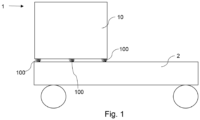
- Fig. 1 shows a first vehicle 1 according to the invention with a vehicle chassis 2.
- a vehicle element 10 is formed on the vehicle chassis 2.
- the vehicle 1 is preferably a military vehicle.
- the vehicle element 10 can be, for example, a cabin, a driver's cab, a platform, a structure or similar act.
- At least one energy absorption device 100 which supports the vehicle element 10 on the vehicle 1, is arranged between the vehicle element 10 and the vehicle chassis 2.
- the energy absorption device 100 serves to protect the vehicle element 10 from a detonation effect and is described in more detail in the 4a to 6 shown.
- the energy absorption device 100 according to 4a to 6 can be found in all vehicles Fig. 1 to 3 .
- Fig. 2 shows a second vehicle 1′ according to the invention, which essentially corresponds to the first vehicle 1, with the difference that the vehicle element 10′ is a floor or intermediate floor.
- the vehicle element 10′ is mounted on the vehicle chassis 2 of the vehicle 1 by means of at least one energy absorption device 100.
- the vehicle element 10' is arranged within a cabin or a driver's cab.
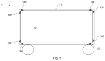
- Fig. 3 shows a third vehicle 1" according to the invention with a vehicle tub 2'.
- a vehicle element 10" is mounted within the vehicle tub 2' by means of at least one energy absorption device 100.
- the vehicle element 10" can be, for example, a vehicle interior or a protective space. Deviating from this Fig. 3
- the vehicle element 10" can also be a floor or intermediate floor.
- the vehicle element 10′′ is connected to the vehicle tub 2′ by several energy absorption devices 100 and is stored within it.
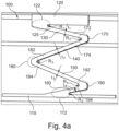
- Fig. 4a shows a schematic representation of an energy absorption device 100 according to the invention in a starting position, i.e. a position in which the energy absorption device 100 is not deformed.
- the energy absorption device 100 includes a first fastening element 110, which can be connected to the vehicle chassis 2 or the vehicle tub 2 'of the vehicle 1.
- the first fastening element 110 is designed as a plate or sheet metal and is connected to the vehicle chassis 2 or the vehicle tub 2 'in the installed state.
- the energy absorption device 100 includes a second fastening element 120, which can be connected to the vehicle element 10 to be protected.
- the second fastening element 110 is preferably also designed as a plate or sheet metal and is connected to the vehicle element 10 in the installed state.
- the wall thickness and the dimensions of the first fastening element 110 and the second fastening element 120 can be adapted to the geometry of the energy absorption device 100 in different ways. Like in the Fig. 1 shown, the first fastening element 110 can have a smaller wall thickness and be wider than the second fastening element 120.
- At least two webs 130, 140, 150, 160 are arranged between the first and second fastening elements 110, 120.
- four webs 130, 140, 150, 160 are shown.
- the first fastening element 110, the second fastening element 120, the webs 130, 140, 150, 160 and the deformation zones 172, 174, 182, 184, 192, 194 are arranged such that they are one above the other in a common plane E are arranged, the common plane E being perpendicular to the two fastening elements 110, 120.
- the webs 130, 140, 150, 160 are alternately arranged one above the other in a zigzag manner in different directions. In other words, the webs 130, 140, 150, 160 are arranged one above the other in an accordion-like manner.
- the webs 130, 140, 150, 160 are each designed to be flexible.
- the length of the webs 130, 140, 150, 160 can differ from one another, so that, for example, a first web 130 and a fourth web 160, which are connected to the fastening elements 110, 120, are shorter than a second web 140 and third web 150.
- the different lengths of the webs 130, 140, 150, 160 ensure that they can deflect elastically to different degrees and result in a defined bending pattern of the energy absorption device 100 in the event of an elastic deformation.
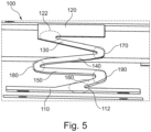
- a bending figure as a result of an elastic deformation is, for example, in Fig. 5 shown.
- Bending-stiffened corners 170, 180, 190 are formed between the webs 130, 140, 150, 160.
- the bend-stiffened corners 170, 180, 190 are designed in such a way that they essentially do not bend and ensure that when the webs 130, 140, 150, 160 are elastically deformed, the bend-stiffened corners 170, 180, 190 ensure that the Webs 130, 140, 150, 160 cannot be folded together due to deformation of the corners 170, 180, 190. This ensures that, in addition to elastic deformation in the event of a With greater deflection, plastic deformation of the deformation zones 172, 174, 182, 184, 192, 194 can take place.
- the webs 130, 140, 150, 160 each have at least one deformation zone 172, 174, 182, 184, 192, 194.
- the deformation zones 172, 174, 182, 184, 192, 194 are each formed adjacent to the bend-stiffened corners 170, 180, 190.
- flexurally stiffened transition zones 112, 122 are formed. These have a comparable effect to the bend-stiffened corners 170, 180, 190.
- transition deformation zones 115, 125 are formed adjacent to the flexurally stiffened transition zones 112, 122.
- inner radii R2, R3, R4 are formed between the webs 130, 140, 150, 160 in the deformation zones 172, 174, 182, 184, 192, 194 and/or inner radii R1, R5 in the transition zones 112, 122.
- Fig. 4a are the inner radii R2, R3, R4, which are formed between the webs 130, 140, 150, 160 in the rigid corners 170, 180, 190, increasing from the second fastening element 120 to the first fastening element 110.
- a fourth radius R4 between the third web 150 and fourth web 160 is largest.
- a third radius R3 between the second web 140 and the third web 150 is smaller than the fourth radius (R3 ⁇ R4).
- a second radius R2 between the first web 130 and the second web 140 is smaller than the third radius R3.
- the thickness t1, t2, t3, t4 of the webs 130, 140, 150, 160 can be made larger from the second fastening element 120 towards the first fastening element 110, so that the energy absorption device 100 has a progressive spring characteristic.
- the following mathematical relationship applies to the thicknesses t1 to t4: t1 ⁇ t2 ⁇ t3 ⁇ t4.
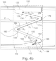
- Fig. 4b clearly illustrates the location of level E again, with level E marked by hatching.
- the plane E lies perpendicular to the first and second fastening elements 110, 120.
- the first fastening element 110, the second fastening element 120, the at least two webs 130, 140, 150, 160 and the at least one deformation zone 172, 174, 182, 184, 192, 194 are arranged in such a way that they lie one above the other in plane E.
- Fig. 5 shows a schematic representation of the energy absorption device 100 according to the invention in an intermediate position in which the energy absorption device 100 is elastically deformed.
- the rigid corners 170, 180, 190 are essentially undeformed in this intermediate position and the webs 130, 140, 150, 160 are elastically deformed.
- Fig. 5 shows the energy absorption device 100 in an elastically compressed state.
- Fig. 6 shows a schematic representation of the energy absorption device 100 according to the invention in a deformed position in which the energy absorption device 100 is plastically deformed.
- the deformation zones 172, 174, 182, 184, 192, 194 are designed to be at least partially more difficult to deform from the second fastening element 120 to the first fastening element 110 than the previous deformation zones 172, 174, 182, 184, 192, 194, so that the energy absorption device 100 is a has progressive deformation characteristic.
- a deformation sequence of the deformation zones of the energy absorption device 100 is specified by the different degrees of deformation.
Landscapes
- Engineering & Computer Science (AREA)
- General Engineering & Computer Science (AREA)
- Vibration Dampers (AREA)
- Body Structure For Vehicles (AREA)
Description
Die Erfindung betrifft eine Energieabsorbtionsvorrichtung zum Schutz eines Fahrzeugelements, insbesondere eines Fahrzeugelements eines militärischen Fahrzeugs, vor einer Detonationswirkung, umfassend ein erstes Befestigungselement, das mit einem Fahrzeugchassis oder einer Fahrzeugwanne verbindbar ist und ein zweites Befestigungselement, das mit dem zu schützenden Fahrzeugelement verbindbar ist, wobei zwischen dem ersten und dem zweiten Befestigungselement zumindest zwei Stege angeordnet sind.The invention relates to an energy absorption device for protecting a vehicle element, in particular a vehicle element of a military vehicle, from a detonation effect, comprising a first fastening element which can be connected to a vehicle chassis or a vehicle tub and a second fastening element which can be connected to the vehicle element to be protected, wherein At least two webs are arranged between the first and the second fastening element.
Weiterhin betrifft die Anmeldung ein Fahrzeug mit einer solchen Energieabsorbtionsvorrichtung.Furthermore, the application relates to a vehicle with such an energy absorption device.
Aus der
Aus der
Aufhängungen von Fahrzeugelementen militärischer Fahrzeuge sind z.B. aus
Die
Ausgehend davon, liegt der Erfindung die Aufgabe zugrunde, eine Energieabsorbtionsvorrichtung für ein Fahrzeug, insbesondere ein militärisches Fahrzeug, zu schaffen, die kleinbauend ist und diesen Zielkonflikt löst.Based on this, the invention is based on the object of creating an energy absorption device for a vehicle, in particular a military vehicle, which is small in size and solves this conflict of objectives.
Diese Aufgabe wird durch die Energieabsorbtionsvorrichtung des Anspruchs 1 gelöst. Vorteilhafte Ausgestaltungen und Weiterbildungen sind Gegenstand der jeweiligen Unteransprüche.This task is solved by the energy absorption device of
Erfindungsgemäß wird eine Energieabsorbtionsvorrichtung zum Schutz eines Fahrzeugelements, insbesondere eines militärischen Fahrzeugs, vor einer Detonationswirkung, bereitgestellt. Die Energieabsorbtionsvorrichtung umfasst ein erstes Befestigungselement, das mit einem Fahrzeugchassis oder einer Fahrzeugwanne verbindbar ist und ein zweites Befestigungselement, das mit dem zu schützenden Fahrzeugelement verbindbar ist. Zwischen dem ersten und dem zweiten Befestigungselement sind zumindest zwei Stege angeordnet. Die zumindest zwei Stege sind derart angeordnet sind, dass diese übereinander in einer gemeinsamen Ebene liegen.According to the invention, an energy absorption device is provided for protecting a vehicle element, in particular a military vehicle, from a detonation effect. The energy absorption device includes a first fastening element that is connectable to a vehicle chassis or a vehicle tub and a second fastening element that is connectable to the vehicle element to be protected. At least two webs are arranged between the first and second fastening elements. The at least two webs are arranged in such a way that they lie one above the other in a common plane.
Weiterhin wird erfindungsgemäß ein Fahrzeug, insbesondere ein militärisches Fahrzeug, bereitgestellt, umfassend eine solche oder wie nachstehend beschriebene Energieabsorbtionsvorrichtung und ein Fahrzeugelement, wobei das Fahrzeugelement über die Energieabsorbtionsvorrichtung mit dem Fahrzeug verbunden ist.Furthermore, according to the invention, a vehicle, in particular a military vehicle, is provided, comprising such an energy absorption device or as described below and a vehicle element, the vehicle element being connected to the vehicle via the energy absorption device.
Bei dem Fahrzeug kann es sich beispielsweise um ein Rad- oder Kettenfahrzeug handeln. Das Kettenfahrzeug kann beispielsweise ein Bergepanzer, ein Pionierpanzer, ein Minenräumpanzer, ein Schützenpanzer oder ein Kampfpanzer sein. Das Radfahrzeug kann beispielsweise ein schwerer Lastwagen, ein Sattelzug, ein Kran oder ein Radpanzer sein.The vehicle can be, for example, a wheeled or tracked vehicle. The tracked vehicle can be, for example, a recovery vehicle, an engineer tank, a mine clearing vehicle, an armored personnel carrier or a main battle tank. The wheeled vehicle can be, for example, a heavy truck, a tractor-trailer, a crane or a wheeled tank.
Durch die erfindungsgemäße Energieabsorbtionsvorrichtung wird eine kleinbauende Energieabsorbtionsvorrichtung geschaffen, die einerseits eine elastische Lagerung des damit verbindbaren Fahrzeugelements bereitstellt und gleichermaßen eine hohe Energie in Form von Formänderungsarbeit im Fall einer Detonation absorbieren ist kann.The energy absorption device according to the invention creates a small-sized energy absorption device which, on the one hand, provides elastic support for the vehicle element that can be connected to it and, at the same time, can absorb high energy in the form of deformation work in the event of a detonation.
Das Fahrzeugelement, das mit der Energieabsorbtionsvorrichtung verbunden ist, kann beispielsweise eine Kabine oder ein Schutzraum eines Fahrzeugs sein. Insbesondere kann es sich bei der Kabine um eine geschützte Kabine handeln. Ebenso kann das Fahrzeugelement ein Aufbau, eine Plattform, ein Boden, ein Schwingungsboden, ein Zwischenboden, eine Bodenplatte oder ein Bestandteil eines der vorgenannten Elemente sein.The vehicle element that is connected to the energy absorption device can be, for example, a cabin or a shelter of a vehicle. In particular, the cabin can be a protected cabin. Likewise, the vehicle element can be a structure, a platform, a floor, a vibrating floor, an intermediate floor, a floor plate or a component of one of the aforementioned elements.
Ferner kann das Fahrzeugelement ein Fußblech, eine Sitzeinrichtung, eine Waffenanlage, eine Gerätehalterung, ein Regal sein oder ein Bestandteil eines der vorgenannten Elemente sein.Furthermore, the vehicle element can be a base plate, a seat device, a weapon system, a device holder, a shelf or a component of one of the aforementioned elements.
Durch die erfindungsgemäße Energieabsorbtionsvorrichtung wird das Fahrzeugelement vor einer Detonationswirkung geschützt, wie diese z.B. durch Mine oder eine Sprengfalle hervorgerufen werden kann.The energy absorption device according to the invention protects the vehicle element from a detonation effect, such as can be caused, for example, by a mine or a booby trap.
Die erfindungsgemäße Energieabsorbtionsvorrichtung macht es möglich, dass diese im Falle einer Detonation kontrolliert plastisch verformt wird und das damit verbindbare Fahrzeugelement keinen Schaden nimmt.The energy absorption device according to the invention makes it possible for it to be plastically deformed in a controlled manner in the event of a detonation and for the vehicle element that can be connected to it not to be damaged.
Vorzugsweise kann vorgesehen sein, dass die Stege zumindest eine Deformationszone aufweisen.It can preferably be provided that the webs have at least one deformation zone.
Die zumindest eine Deformationszone ist eine Zone, in der sich die Stege plastisch Verformen, wenn diese entsprechend stark ausgelenkt werden. Dies geschieht durch die Konstruktion der Energieabsorbtionsvorrichtung, welche bedingt, dass sich die Stege zuerst in den Deformationszonen deformieren.The at least one deformation zone is a zone in which the webs deform plastically when they are deflected to a correspondingly strong extent. This happens due to the design of the energy absorption device, which requires that the webs first deform in the deformation zones.
Ferner kann vorgesehen sein, dass in den Deformationszonen die Stege durch Werkstoffwahl oder Geometrie derart geschwächt sind, dass diese in den Deformationszonen zuerst deformieren.Furthermore, it can be provided that the webs in the deformation zones are weakened by the choice of material or geometry in such a way that they deform first in the deformation zones.
Ferner kann vorgesehen sein, dass das erste Befestigungselement, das zweite Befestigungselement, die zumindest zwei Stege und die zumindest eine Deformationszone derart angeordnet sind, dass diese übereinander in der Ebene liegen, die senkrecht zu dem ersten und dem zweiten Befestigungselement liegt.Furthermore, it can be provided that the first fastening element, the second fastening element, the at least two webs and the at least one deformation zone are arranged such that they lie one above the other in the plane that is perpendicular to the first and the second fastening element.
Dabei sind die Befestigungselemente und die Stege der Energieabsorbtionsvorrichtung ziehharmonikaartig in einer gemeinsamen Ebene angeordnet, sodass eine kleinbauende Energieabsorbtionsvorrichtung geschaffen wird.The fastening elements and the webs of the energy absorption device are arranged in an accordion-like manner in a common plane, so that a small energy absorption device is created.
In Weiterbildung der Energieabsorbtionsvorrichtung kann vorgesehen sein, dass die Stege biegeelastisch ausgebildet sind, sodass die Energieabsorbtionsvorrichtung das Fahrzeugelement federnd lagert.In a further development of the energy absorption device, it can be provided that the webs are designed to be flexible, so that the energy absorption device resiliently supports the vehicle element.
Hierdurch wird erreicht, dass die Energieabsorbtionsvorrichtung eine elastische Lagerung des Fahrzeugelements erlaubt, sofern die Auslenkung nicht zu groß wird. Somit kann in normalen Fahrsituationen des Fahrzeugs eine Lagerung des Fahrzeugelements stattfinden, wohingegen zum Schutz vor einer Detonationswirkung eine Energieabsorbtion durch plastische Verformung realisiert ist.This ensures that the energy absorption device allows elastic mounting of the vehicle element as long as the deflection does not become too large. Thus, in normal driving situations of the vehicle, storage of the vehicle element can take place, whereas energy absorption is realized through plastic deformation to protect against a detonation effect.
Nach einer Ausgestaltung ist vorgesehen, dass zwischen den Befestigungseinrich-tungen und den jeweils angrenzenden Stegen biegeversteifte Übergangszonen ausgebildet sind.According to one embodiment, it is provided that flexurally stiffened transition zones are formed between the fastening devices and the respective adjacent webs.
Durch Ausbildung der biegeversteiften, insbesondere im Wesentlichen biegesteifen, Übergangszonen wird erreicht, dass die Stege der Energieabsorbtionsvorrichtung nicht einfach abknicken oder abbrechen, sondern im Bereich der Übergangsdeformationszonen der Stege eine definierte Deformation erreicht wird.By designing the flexurally stiff, in particular essentially flexurally rigid, transition zones, it is achieved that the webs of the energy absorption device do not simply bend or break off, but rather a defined deformation is achieved in the area of the transition deformation zones of the webs.
Ferner kann in Weiterbildung vorgesehen sein, dass an den biegeversteiften Übergangszonen angrenzend Übergangsdeformationszonen ausgebildet sind.Furthermore, in a further development it can be provided that transition deformation zones are formed adjacent to the flexurally stiffened transition zones.
Weiterhin ist nach einer Ausgestaltung vorgesehen, dass zwischen den Stegen jeweils biegeversteifte, insbesondere im Wesentlichen biegesteife, Ecken ausgebildet sind.Furthermore, according to one embodiment, it is provided that bend-stiffened, in particular substantially bend-resistant, corners are formed between the webs.
Hierdurch wird erreicht, dass gezielt die Stege und nicht die Ecken eine Deformation erfahren. Ferner wird erreicht, dass die Energieabsorbtionsvorrichtung in den Ecken nicht einfach abknickt oder zusammenfällt und ein auf Block liegen der Stege vermieden wird. Die Stege können somit gezielt auf Biegung belastet werden. Zudem ist auf diese Weise sichergestellt, dass eine plastische Deformation einer Deformationszone des Steges möglich ist, die im Federweg einer elastischen Deformation eines Steges nachgeordnet ist. Somit ist sichergestellt, dass sowohl eine ausreichende elastische Federung als auch eine plastische Deformation möglich ist.This ensures that the webs and not the corners undergo deformation. Furthermore, it is ensured that the energy absorption device does not simply bend or collapse in the corners and that the webs are prevented from lying on a block. The webs can therefore be subjected to specific bending loads. In addition, it is ensured in this way that a plastic deformation of a deformation zone of the web is possible, which is subordinate to an elastic deformation of a web in the spring travel. This ensures that both sufficient elastic suspension and plastic deformation are possible.
In Ausgestaltung kann ferner vorgesehen sein, dass an den biegeversteiften Ecken angrenzend die Deformationszonen ausgebildet sind.In an embodiment it can also be provided that the deformation zones are formed adjacent to the bending-stiffened corners.
Weiterhin kann vorgesehen sein, dass die Deformationszonen von dem zweiten Befestigungselement zum ersten Befestigungselement hin zumindest teilweise schwerer deformierbar ausgebildet sind als die vorhergehenden Deformationszonen, sodass die Energieabsorbtionsvorrichtung eine progressive Deformationskennlinie aufweist.Furthermore, it can be provided that the deformation zones from the second fastening element towards the first fastening element are at least partially designed to be more difficult to deform than the previous deformation zones, so that the energy absorption device has a progressive deformation characteristic.
Hierdurch wird die Deformationsreihenfolge gezielt beeinflusst, sodass die Deformationszonen in einer definierten Reihenfolge deformiert werden.This specifically influences the deformation sequence so that the deformation zones are deformed in a defined order.
Ferner kann vorgesehen sein, dass die Dicke der Stege von dem zweiten Befestigungselement zum ersten Befestigungselement hin größer wird, sodass die Energieabsorbtionsvorrichtung eine progressive Federkennlinie aufweist.Furthermore, it can be provided that the thickness of the webs increases from the second fastening element towards the first fastening element, so that the energy absorption device has a progressive spring characteristic.
Hierdurch wird erreicht, dass die elastische Verformbarkeit der Stege unterschiedlich ausgebildet ist und die Federkennlinie der Energieabsorbtionsvorrichtung gezielt beeinflusst werden kann.This ensures that the elastic deformability of the webs is designed differently and the spring characteristic of the energy absorption device can be influenced in a targeted manner.
Die Federkennlinie kann alternativ degressiv sein.Alternatively, the spring characteristic can be degressive.
Ferner kann vorgesehen sein, dass die Stege in alternierender Richtung zick-zack-artig angeordnet sind.Furthermore, it can be provided that the webs are arranged in a zigzag manner in an alternating direction.
Hierdurch wird eine besonders platzsparende Energieabsorbtionsvorrichtung geschaffen.This creates a particularly space-saving energy absorption device.
In Ausgestaltung der Energieabsorbtionsvorrichtung kann vorgesehen sein, dass Innenradien zwischen den Stegen in biegesteifen Ecken und/oder Innenradien in den Übergangszonen ausgebildet sind.In an embodiment of the energy absorption device, it can be provided that inner radii between the webs are formed in rigid corners and/or inner radii in the transition zones.
Durch das Ausbilden von Innenradien werden gezielt Kerbspannungen in den Deformationszonen induziert. Durch die Größe des Radius der Innenradien lässt sich die auftretende Kerbspannung beeinflussen, sodass sich die Größe der Kerbspannungen und auch die Grenze in der die Deformation eintritt durch den Radius einstellen lässt.By forming inner radii, notch stresses are specifically induced in the deformation zones. The notch stress that occurs can be influenced by the size of the radius of the inner radii, so that the size of the notch stress and also the limit at which the deformation occurs can be adjusted by the radius.
Erfindungsgemäß werden die Innenradien zwischen den Stegen in biegesteifen Ecken und/oder die Innenradien in den Übergangsdeformationszonen von dem zweiten Befestigungselement zum ersten Befestigungselement hin größer.According to the invention, the inner radii between the webs in rigid corners and/or the inner radii in the transition deformation zones from the second fastening element to the first fastening element become larger.
Hierdurch wird die Deformationsreihenfolge gezielt eingestellt, sodass eine Deformation vom zweiten Befestigungselement zum ersten Befestigungselement hin nach und nach eintritt.As a result, the deformation sequence is set specifically so that a deformation from the second fastening element to the first fastening element occurs gradually.
Hierdurch wird erreicht, dass die Kerbspannungen innerhalb der Deformationszonen unmittelbar am ersten Befestigungselement am höchsten sind und auch die Deformation zuerst in der Nähe des Chassis eintritt.This ensures that the notch stresses within the deformation zones are highest directly on the first fastening element and the deformation also occurs first in the vicinity of the chassis.
Alternativ zu der oben genannten Reihenfolge ist es jedoch auch möglich, dass die Innenradien zwischen den Stegen in biegesteifen Ecken und/oder die Innenradien in den Übergangszonen von dem ersten Befestigungselement zum zweiten Befestigungselement hin größer werden. Hierdurch wird erreicht, dass die Kerbspannungen innerhalb der Deformationszonen unmittelbar am zweiten Befestigungselement am höchsten sind und die Deformation zuerst in der Nähe des Fahrzeugelements eintritt.As an alternative to the above-mentioned sequence, it is also possible for the inner radii between the webs in rigid corners and/or the inner radii in the transition zones from the first fastening element to the second fastening element to become larger. This ensures that the notch stresses within the deformation zones are highest directly on the second fastening element and the deformation occurs first in the vicinity of the vehicle element.
Nachfolgend soll die Erfindung anhand von Ausführungsbeispielen mit Bezug auf die Zeichnungen erläutert werden.The invention will be explained below using exemplary embodiments with reference to the drawings.
Es zeigen:
- Fig. 1
- eine schematische Darstellung eines ersten erfindungsgemäßen Fahrzeugs mit zumindest einer erfindungsgemäßen Deformationsvorrichtung;
- Fig. 2
- eine schematische Darstellung eines zweiten erfindungsgemäßen Fahrzeugs mit zumindest einer erfindungsgemäßen Deformationsvorrichtung;
- Fig. 3
- eine schematische Darstellung eines dritten erfindungsgemäßen Fahrzeugs mit zumindest einer erfindungsgemäßen Deformationsvorrichtung;
- Fig. 4a
- eine schematische Darstellung einer erfindungsgemäßen Energieabsorbtionsvorrichtung in einer Ausgangsstellung;
- Fig. 4b
- eine schematische Darstellung der erfindungsgemäßen Energieabsorbtionsvorrichtung in einer Ausgangsstellung mit Kenntlichmachung der Ebene E;
- Fig. 5
- eine schematische Darstellung der erfindungsgemäßen Energieabsorbtionsvorrichtung in einer Zwischenstellung; und
- Fig. 6
- eine schematische Darstellung der erfindungsgemäßen Energieabsorbtionsvorrichtung in einer deformierten Stellung.
- Fig. 1
- a schematic representation of a first vehicle according to the invention with at least one deformation device according to the invention;
- Fig. 2
- a schematic representation of a second vehicle according to the invention with at least one deformation device according to the invention;
- Fig. 3
- a schematic representation of a third vehicle according to the invention with at least one deformation device according to the invention;
- Fig. 4a
- a schematic representation of an energy absorption device according to the invention in an initial position;
- Fig. 4b
- a schematic representation of the energy absorption device according to the invention in a starting position with plane E identified;
- Fig. 5
- a schematic representation of the energy absorption device according to the invention in an intermediate position; and
- Fig. 6
- a schematic representation of the energy absorption device according to the invention in a deformed position.
Die Energieabsorbtionsvorrichtung 100 dient zum Schutz des Fahrzeugelements 10, vor einer Detonationswirkung und ist detaillierter in den
Gemäß
Die Energieabsorbtionsvorrichtung 100 umfasst ein erstes Befestigungselement 110, das mit dem Fahrzeugchassis 2 oder der Fahrzeugwanne 2' des Fahrzeugs 1 verbindbar ist. Das erste Befestigungselement 110 ist als Platte oder Blech ausgebildet und ist im eingebauten Zustand mit dem Fahrzeugchassis 2 oder der Fahrzeugwanne 2'verbunden.The
Weiterhin umfasst die Energieabsorbtionsvorrichtung 100 ein zweites Befestigungselement 120, das mit dem zu schützenden Fahrzeugelement 10 verbindbar ist. Das zweite Befestigungselement 110 ist vorzugsweise ebenfalls als Platte oder Blech ausgebildet und ist im eingebauten Zustand mit dem Fahrzeugelement 10 verbunden.Furthermore, the
Die Wandstärke und die Ausmaße des ersten Befestigungselements 110 und des zweiten Befestigungselements 120 können voneinander abweichend an die Geometrie der Energieabsorbtionsvorrichtung 100 angepasst sein. Wie in der
Zwischen dem ersten und dem zweiten Befestigungselement 110, 120 sind zumindest zwei Stege 130, 140, 150, 160 angeordnet. In Ausgestaltung können wie in
Wie in
Die Stege 130, 140, 150, 160 sind dabei alternierend in unterschiedlicher Richtung zick-zack-artig übereinander angeordnet. Mit anderen Worten sind die Stege 130, 140, 150, 160 ziehharmonikaartig übereinander angeordnet.The
Um eine federnde Lagerung des Fahrzeugelements 10 durch die Energieabsorbtionsvorrichtung 100 zu erreichen, sind die Stege 130, 140, 150, 160 jeweils biegeelastisch ausgebildet.In order to achieve resilient mounting of the
Die Länge der Stege 130, 140, 150, 160 kann voneinander abweichen, sodass beispielsweise ein erster Steg 130 und ein vierter Steg 160, die mit den Befestigungselementen 110, 120 verbunden sind, kürzer sind, als ein zweiter Steg 140 und dritter Steg 150.The length of the
Durch die unterschiedliche Länge der Stege 130, 140, 150, 160 wird erreicht, dass diese unterschiedlich stark elastisch einfedern können und sich eine definierte Biegefigur der Energieabsorbtionsvorrichtung 100 bei einer elastischen Deformation ergibt. Eine solche Biegefigur infolge einer elastischen Deformation ist beispielsweise in
Zwischen den Stegen 130, 140, 150, 160 sind jeweils biegeversteifte Ecken 170, 180, 190 ausgebildet. Die biegeversteiften Ecken 170, 180, 190 sind derart ausgebildet, dass sich diese im Wesentlichen nicht verbiegen und dafür sorgen, dass bei einer elastischen Verformung der Stege 130, 140, 150, 160 die biegeversteiften Ecken 170, 180, 190 dafür sorgen, dass die Stege 130, 140, 150, 160 nicht durch Deformation der Ecken 170, 180, 190 zusammengefaltet werden. Hierdurch wird erreicht, dass neben einer elastischen Deformation im Falle einer stärkeren Auslenkung eine plastische Deformation der Deformationszonen 172, 174, 182, 184, 192, 194 stattfinden kann.Bending-stiffened
Wie in
Zwischen den Befestigungseinrichtungen 110, 120 und den jeweils angrenzenden Stegen 130, 160 sind biegeversteifte Übergangszonen 112, 122 ausgebildet. Diese haben eine vergleichbare Wirkung wie die biegeversteiften Ecken 170, 180, 190.Between the
An den biegeversteiften Übergangszonen 112, 122 sind angrenzend die Übergangsdeformationszonen 115, 125 ausgebildet.The
Wie in der
Gemäß
In Ausgestaltung ist ein vierter Radius R4 zwischen dem dritten Steg 150 und vierten Steg 160 am größten. Ein dritter Radius R3 zwischen dem zweiten Steg 140 und dem dritten Steg 150 ist kleiner als der vierte Radius (R3<R4). Ein zweiter Radius R2 zwischen dem ersten Steg 130 und dem zweiten Steg 140 ist kleiner als der dritte Radius R3. Es gilt für die Radien R2 bis R4 folgender mathematischer Zusammenhang: R2<R3<R4.In an embodiment, a fourth radius R4 between the
Die Innenradien R1, R5 in den Übergangszonen 112, 122 sind gemäß
Die Dicke t1, t2, t3, t4 der Stege 130, 140, 150, 160 kann von dem zweiten Befestigungselement 120 zum ersten Befestigungselement 110 hin größer ausgebildet sein, sodass die Energie- absorbtionsvorrichtung 100 eine progressive Federkennlinie aufweist. Es gilt für die Dicken t1 bis t4 folgender mathematischer Zusammenhang: t1<t2<t3<t4.The thickness t1, t2, t3, t4 of the
Die Deformationszonen 172, 174, 182, 184, 192, 194 sind von dem zweiten Befestigungselement 120 zum ersten Befestigungselement 110 hin zumindest teilweise schwerer deformierbar ausgebildet als die vorhergehenden Deformationszonen 172, 174, 182, 184, 192, 194, sodass die Energieabsorbtionsvorrichtung 100 eine progressive Deformationskennlinie aufweist. Zudem wird durch die unterschiedlich starke Deformation eine Deformationsreihenfolge der Deformationszonen der Energieabsorbtionsvorrichtung 100 vorgegeben.The
Soweit sich die vorstehende Offenbarung auf eine die Energieabsorbtionsvorrichtung 100 als solche bezieht, so gilt diese gleichzeitig auch für ein Fahrzeug mit einer solchen Energieabsorbtionsvorrichtung 100 als offenbart.Insofar as the above disclosure relates to an
- 11
- erstes Fahrzeugfirst vehicle
- 1'1'
- zweites Fahrzeugsecond vehicle
- 1"1"
- drittes Fahrzeugthird vehicle
- 22
- FahrzeugchassisVehicle chassis
- 2'2'
- Fahrzeugwannevehicle tub
- 1010
- FahrzeugelementVehicle element
- 10'10'
- FahrzeugelementVehicle element
- 10"10"
- FahrzeugelementVehicle element
- 100100
- EnergieabsorbtionsvorrichtungEnergy absorption device
- 110110
- erstes Befestigungselementfirst fastener
- 112112
- erste Übergangszonefirst transition zone
- 115115
- erste Übergangsdeformationszonefirst transition deformation zone
- 120120
- zweites Befestigungselementsecond fastener
- 122122
- zweite Übergangszonesecond transition zone
- 125125
- zweite Übergangsdeformationszonesecond transition deformation zone
- 130130
- erster Stegfirst bridge
- 140140
- zweiter Stegsecond bridge
- 150150
- dritter Stegthird bridge
- 160160
- vierter Stegfourth bridge
- 170170
- erste Deformationszonefirst deformation zone
- 180180
- zweite Deformationszonesecond deformation zone
- 190190
- dritte Deformationszonethird deformation zone
- R1R1
- erster Radiusfirst radius
- R2R2
- zweiter Radiussecond radius
- R3R3
- dritter Radiusthird radius
- R4R4
- vierter Radiusfourth radius
- R5R5
- fünfter Radiusfifth radius
- EE
- Ebenelevel
- t1t1
- Dicke des ersten StegsThickness of the first bar
- t2t2
- Dicke des zweiten StegsThickness of the second bar
- t3t3
- Dicke des dritten StegsThickness of the third bar
- t4t4
- Dicke des vierten StegsThickness of the fourth bar
Claims (11)
- Energy absorption device (100) for protecting a vehicle element (10, 10', 10"), in particular a military vehicle (1, 1', 1"), from a detonation impact, comprising a first securing element (110) which can be connected to a vehicle chassis (2) and/or a vehicle cradle (2), and comprising a second securing element (120) which can be connected to the vehicle element (10, 10', 10") to be protected,at least two connecting pieces (130, 140, 150, 160) being arranged between the first and the second securing element (110, 120),the at least two connecting pieces (130, 140, 150, 160) being arranged such that they lie one above the other in a common plane (E),characterized in thatflexurally rigid corners (170, 180, 190) are formed in each case between the connecting pieces (130, 140, 150, 160), inner radii (R2, R3, R4) becoming greater between the connecting pieces (130, 140, 150, 160) in the flexurally rigid corners (170, 180, 190) from the second securing element (120) toward the first securing element (110); and/orin that flexurally rigid transition zones (112, 122) are formed between the securing elements (110, 120) and each of the adjacent connecting pieces (130, 160), inner radii (R1, R5) becoming greater in the transition zones (112, 122) from the second securing element (120) toward the first securing element (110).
- Energy absorption device (100) according to claim 1,
characterized in that the connecting pieces (130, 140, 150, 160) have at least one deformation zone (172, 174, 182, 184, 192, 194). - Energy absorption device (100) according to claim 2,
characterized in that the first securing element (110), the second securing element (120), the at least two connecting pieces (130, 140, 150, 160) and the at least one deformation zone (172, 174, 182, 184, 192, 194) are arranged such that they lie one above the other in the plane (E) which is perpendicular to the first and the second securing element (110, 120). - Energy absorption device (100) according to any of the preceding claims, characterized in that the connecting pieces (130, 140, 150, 160) are flexurally elastic.
- Energy absorption device (100) according to any of claims 1 to 4, characterized in that transition deformation zones (115, 125) are adjacent to the flexurally rigid transition zones (112, 122).
- Energy absorption device (100) according to claim 2 or claim 3 as well as according to claim 4 or claim 5 when referring back to claim 2 or claim 3, characterized in that the deformation zones (172, 174, 182, 184, 192, 194) are adjacent to the flexurally rigid corners (170, 180, 190).
- Energy absorption device (100) according to any of claims 2, 3 or 6 as well as according to claim 4 or claim 5 when referring back to claim 2 or claim 3, characterized in that the deformation zones (172, 174, 182, 184, 192, 194) are designed to be at least partly more difficult to deform from the second securing element (120) toward the first securing element (110) than the preceding deformation zones (172, 174, 182, 184, 192, 194) so that the energy absorption device (100) has a progressive deformation characteristic curve.
- Energy absorption device (100) according to any of the preceding claims, characterized in that a thickness (t1, t2, t3, t4) of the connecting pieces (130, 140, 150, 160) is greater from the second securing element (120) toward the first securing element (110) so that the energy absorption device (100) has a progressive spring characteristic curve.
- Energy absorption device (100) according to any of the preceding claims, characterized in that the connecting pieces (130, 140, 150, 160) are arranged in an alternating direction in a sawtooth-like manner.
- Vehicle (1, 1', 1") comprising an energy absorption device (100) according to any of claims 1-9 and a vehicle element (10, 10', 10"), wherein the vehicle element (10, 10', 10") is connected to the vehicle (1, 1', 1") via the energy absorption device (100).
- Vehicle (1, 1', 1") according to claim 10, wherein the vehicle element (10, 10', 10") is a cabin, in particular a vehicle cabin, a floor, an intermediate floor, a structure, a foot plate, a seat apparatus, a weapon installation, an appliance holder or a shelf.
Applications Claiming Priority (2)
| Application Number | Priority Date | Filing Date | Title |
|---|---|---|---|
| DE102019114514.7A DE102019114514A1 (en) | 2019-05-29 | 2019-05-29 | Energy absorbing device and vehicle |
| PCT/EP2020/062269 WO2020239362A1 (en) | 2019-05-29 | 2020-05-04 | Detonation energy absorption device and vehicle equipped with same |
Publications (2)
| Publication Number | Publication Date |
|---|---|
| EP3977039A1 EP3977039A1 (en) | 2022-04-06 |
| EP3977039B1 true EP3977039B1 (en) | 2023-11-22 |
Family
ID=70554052
Family Applications (1)
| Application Number | Title | Priority Date | Filing Date |
|---|---|---|---|
| EP20724059.9A Active EP3977039B1 (en) | 2019-05-29 | 2020-05-04 | Blast wave energy absorption device and vehicle equipped with such a device |
Country Status (11)
| Country | Link |
|---|---|
| EP (1) | EP3977039B1 (en) |
| AU (1) | AU2020284371B2 (en) |
| CA (1) | CA3142087C (en) |
| DE (1) | DE102019114514A1 (en) |
| DK (1) | DK3977039T3 (en) |
| ES (1) | ES2969453T3 (en) |
| FI (1) | FI3977039T3 (en) |
| HU (1) | HUE065437T2 (en) |
| PL (1) | PL3977039T3 (en) |
| SG (1) | SG11202113139SA (en) |
| WO (1) | WO2020239362A1 (en) |
Family Cites Families (13)
| Publication number | Priority date | Publication date | Assignee | Title |
|---|---|---|---|---|
| US4752058A (en) * | 1986-12-04 | 1988-06-21 | Weber Milton N | Shock-absorbing support rail |
| US5280889A (en) * | 1991-04-08 | 1994-01-25 | Texas Instruments Incorporated | Shock isolator |
| DE4341952B4 (en) * | 1992-12-18 | 2010-01-21 | Volkswagen Ag | Vehicle seat with a fully or partially folding backrest |
| US5813649A (en) * | 1996-03-13 | 1998-09-29 | Simula, Inc. | Energy-absorbing deformable bracket |
| US6394241B1 (en) * | 1999-10-21 | 2002-05-28 | Simula, Inc. | Energy absorbing shear strip bender |
| DE10033340C1 (en) * | 2000-07-08 | 2001-10-25 | Daimler Chrysler Ag | Seat fixing device, for vehicle, has rail in which seat moves and at least one foot element connected between rail and vehicle floor and having deformation section to absorb energy in accident |
| IL160939A (en) * | 2004-03-18 | 2010-11-30 | Plasan Kibbutz Sasa | Energy absorbing device for a vechicle seat |
| FR2901750A1 (en) * | 2006-05-31 | 2007-12-07 | Jean Michel Ritter | Device for progressively absorbing an acceleration induced at an occupant seat of a vehicle with large wheels or a endless track, comprises panels that are preformed and assembled to deform itself progressively under the effect of crushing |
| DE102007002576A1 (en) * | 2007-01-11 | 2008-07-17 | Rheinmetall Landsysteme Gmbh | Decoupled pedal unit in a mine protected, in particular military vehicle |
| DE102008053152B4 (en) * | 2008-10-24 | 2012-05-31 | Krauss-Maffei Wegmann Gmbh & Co. Kg | Deformation element for protecting a device, in particular a footrest plate, in a particular military vehicle |
| DE102010052151A1 (en) * | 2010-11-22 | 2012-05-24 | Liebherr-Werk Bischofshofen Gmbh | Cabin, particularly vehicle driver's cabin for construction vehicle, particularly wheel loader, has hydraulically damped rubber mounting unit and rolling stabilizing unit at rear side of cabin |
| DE102012103036A1 (en) * | 2012-04-10 | 2013-10-10 | Krauss-Maffei Wegmann Gmbh & Co. Kg | Housing, especially against detonation protected vehicle housing |
| DE102012109190B4 (en) * | 2012-09-27 | 2014-05-28 | Krauss-Maffei Wegmann Gmbh & Co. Kg | Deformation element and method for producing a deformation element |
-
2019
- 2019-05-29 DE DE102019114514.7A patent/DE102019114514A1/en active Pending
-
2020
- 2020-05-04 CA CA3142087A patent/CA3142087C/en active Active
- 2020-05-04 SG SG11202113139SA patent/SG11202113139SA/en unknown
- 2020-05-04 EP EP20724059.9A patent/EP3977039B1/en active Active
- 2020-05-04 HU HUE20724059A patent/HUE065437T2/en unknown
- 2020-05-04 PL PL20724059.9T patent/PL3977039T3/en unknown
- 2020-05-04 WO PCT/EP2020/062269 patent/WO2020239362A1/en unknown
- 2020-05-04 DK DK20724059.9T patent/DK3977039T3/en active
- 2020-05-04 AU AU2020284371A patent/AU2020284371B2/en active Active
- 2020-05-04 FI FIEP20724059.9T patent/FI3977039T3/en active
- 2020-05-04 ES ES20724059T patent/ES2969453T3/en active Active
Also Published As
| Publication number | Publication date |
|---|---|
| ES2969453T3 (en) | 2024-05-20 |
| SG11202113139SA (en) | 2021-12-30 |
| CA3142087A1 (en) | 2020-12-03 |
| FI3977039T3 (en) | 2024-01-15 |
| WO2020239362A1 (en) | 2020-12-03 |
| CA3142087C (en) | 2024-04-30 |
| AU2020284371B2 (en) | 2023-09-28 |
| EP3977039A1 (en) | 2022-04-06 |
| HUE065437T2 (en) | 2024-05-28 |
| DK3977039T3 (en) | 2024-01-29 |
| PL3977039T3 (en) | 2024-03-25 |
| DE102019114514A1 (en) | 2020-12-03 |
| AU2020284371A1 (en) | 2021-12-23 |
Similar Documents
| Publication | Publication Date | Title |
|---|---|---|
| EP3668777B1 (en) | Vehicle longitudinal beam arrangement | |
| EP2142421B1 (en) | Construction machine | |
| DE102015112506A1 (en) | front end module | |
| DE102014009337B4 (en) | Bumper system for a vehicle | |
| DE102017120739B4 (en) | Protection arrangement for at least one battery module arrangement of a motor vehicle | |
| EP1855901B1 (en) | Device for protecting passengers in a motor vehicle in the event of an energy input caused by a collision and oriented towards a motor vehicle door | |
| DE102018120296A1 (en) | battery case | |
| DE102015224894A1 (en) | Hinterachshilfsrahmen and motor vehicle with such a Hinterachshilfsrahmen | |
| EP3661813B1 (en) | Bumper arrangement with a crossmember and two crash boxes | |
| EP3977039B1 (en) | Blast wave energy absorption device and vehicle equipped with such a device | |
| DE102018112377A1 (en) | Battery arrangement for a motor vehicle with a crash protection element | |
| DE10256000A1 (en) | Shock absorbing and indicating metal box for being positioned behind bumper, comprising openings integrated in corner areas | |
| EP1081451B1 (en) | Device mounted on a vehicle, especially a military tracked vehicle | |
| EP3558757B1 (en) | Bumper arrangement for the front region of a passenger car | |
| DE102014109887B4 (en) | Vehicle body reinforcement structure | |
| DE10357157A1 (en) | Underride protection component for a motor vehicle has protection trim together with strengthening and deformation components for protection of any downwards projecting components | |
| DE102014111794A1 (en) | Stiffening arrangement for a front end of a motor vehicle | |
| DE102017203020A1 (en) | Vehicle, in particular motor vehicle | |
| DE102015004790B4 (en) | Crash structure in a vehicle front area | |
| DE102019114300B4 (en) | Support element for a body panel of a vehicle and vehicle | |
| EP1182421A1 (en) | Protective system for a vehicle against the effects of an explosive device | |
| EP1900615B1 (en) | Protection cover device at the front or rear wall area of a vehicle | |
| DE10031372A1 (en) | Wing fitting for vehicle has support sheet with one upper wall sector angled outwards and second wall sector angled further outwards via bead | |
| DE102023003982A1 (en) | Device for optimizing the crash behavior of a vehicle door | |
| DE102015007756A1 (en) | Side impact beam, side door and vehicle |
Legal Events
| Date | Code | Title | Description |
|---|---|---|---|
| STAA | Information on the status of an ep patent application or granted ep patent |
Free format text: STATUS: UNKNOWN |
|
| STAA | Information on the status of an ep patent application or granted ep patent |
Free format text: STATUS: THE INTERNATIONAL PUBLICATION HAS BEEN MADE |
|
| PUAI | Public reference made under article 153(3) epc to a published international application that has entered the european phase |
Free format text: ORIGINAL CODE: 0009012 |
|
| STAA | Information on the status of an ep patent application or granted ep patent |
Free format text: STATUS: REQUEST FOR EXAMINATION WAS MADE |
|
| 17P | Request for examination filed |
Effective date: 20211117 |
|
| AK | Designated contracting states |
Kind code of ref document: A1 Designated state(s): AL AT BE BG CH CY CZ DE DK EE ES FI FR GB GR HR HU IE IS IT LI LT LU LV MC MK MT NL NO PL PT RO RS SE SI SK SM TR |
|
| DAV | Request for validation of the european patent (deleted) | ||
| DAX | Request for extension of the european patent (deleted) | ||
| GRAP | Despatch of communication of intention to grant a patent |
Free format text: ORIGINAL CODE: EPIDOSNIGR1 |
|
| STAA | Information on the status of an ep patent application or granted ep patent |
Free format text: STATUS: GRANT OF PATENT IS INTENDED |
|
| INTG | Intention to grant announced |
Effective date: 20230725 |
|
| GRAS | Grant fee paid |
Free format text: ORIGINAL CODE: EPIDOSNIGR3 |
|
| GRAA | (expected) grant |
Free format text: ORIGINAL CODE: 0009210 |
|
| STAA | Information on the status of an ep patent application or granted ep patent |
Free format text: STATUS: THE PATENT HAS BEEN GRANTED |
|
| AK | Designated contracting states |
Kind code of ref document: B1 Designated state(s): AL AT BE BG CH CY CZ DE DK EE ES FI FR GB GR HR HU IE IS IT LI LT LU LV MC MK MT NL NO PL PT RO RS SE SI SK SM TR |
|
| REG | Reference to a national code |
Ref country code: GB Ref legal event code: FG4D Free format text: NOT ENGLISH |
|
| REG | Reference to a national code |
Ref country code: CH Ref legal event code: EP |
|
| REG | Reference to a national code |
Ref country code: DE Ref legal event code: R096 Ref document number: 502020006124 Country of ref document: DE |
|
| REG | Reference to a national code |
Ref country code: IE Ref legal event code: FG4D Free format text: LANGUAGE OF EP DOCUMENT: GERMAN |
|
| REG | Reference to a national code |
Ref country code: DK Ref legal event code: T3 Effective date: 20240122 |
|
| REG | Reference to a national code |
Ref country code: NL Ref legal event code: FP |
|
| REG | Reference to a national code |
Ref country code: SE Ref legal event code: TRGR |
|
| REG | Reference to a national code |
Ref country code: GR Ref legal event code: EP Ref document number: 20240400149 Country of ref document: GR Effective date: 20240209 |
|
| REG | Reference to a national code |
Ref country code: LT Ref legal event code: MG9D |
|
| REG | Reference to a national code |
Ref country code: SK Ref legal event code: T3 Ref document number: E 43377 Country of ref document: SK |
|
| PG25 | Lapsed in a contracting state [announced via postgrant information from national office to epo] |
Ref country code: IS Free format text: LAPSE BECAUSE OF FAILURE TO SUBMIT A TRANSLATION OF THE DESCRIPTION OR TO PAY THE FEE WITHIN THE PRESCRIBED TIME-LIMIT Effective date: 20240322 |
|
| PG25 | Lapsed in a contracting state [announced via postgrant information from national office to epo] |
Ref country code: LT Free format text: LAPSE BECAUSE OF FAILURE TO SUBMIT A TRANSLATION OF THE DESCRIPTION OR TO PAY THE FEE WITHIN THE PRESCRIBED TIME-LIMIT Effective date: 20231122 |
|
| PG25 | Lapsed in a contracting state [announced via postgrant information from national office to epo] |
Ref country code: LT Free format text: LAPSE BECAUSE OF FAILURE TO SUBMIT A TRANSLATION OF THE DESCRIPTION OR TO PAY THE FEE WITHIN THE PRESCRIBED TIME-LIMIT Effective date: 20231122 Ref country code: IS Free format text: LAPSE BECAUSE OF FAILURE TO SUBMIT A TRANSLATION OF THE DESCRIPTION OR TO PAY THE FEE WITHIN THE PRESCRIBED TIME-LIMIT Effective date: 20240322 Ref country code: BG Free format text: LAPSE BECAUSE OF FAILURE TO SUBMIT A TRANSLATION OF THE DESCRIPTION OR TO PAY THE FEE WITHIN THE PRESCRIBED TIME-LIMIT Effective date: 20240222 Ref country code: PT Free format text: LAPSE BECAUSE OF FAILURE TO SUBMIT A TRANSLATION OF THE DESCRIPTION OR TO PAY THE FEE WITHIN THE PRESCRIBED TIME-LIMIT Effective date: 20240322 |
|
| REG | Reference to a national code |
Ref country code: ES Ref legal event code: FG2A Ref document number: 2969453 Country of ref document: ES Kind code of ref document: T3 Effective date: 20240520 |
|
| REG | Reference to a national code |
Ref country code: HU Ref legal event code: AG4A Ref document number: E065437 Country of ref document: HU |
|
| PG25 | Lapsed in a contracting state [announced via postgrant information from national office to epo] |
Ref country code: RS Free format text: LAPSE BECAUSE OF FAILURE TO SUBMIT A TRANSLATION OF THE DESCRIPTION OR TO PAY THE FEE WITHIN THE PRESCRIBED TIME-LIMIT Effective date: 20231122 Ref country code: LV Free format text: LAPSE BECAUSE OF FAILURE TO SUBMIT A TRANSLATION OF THE DESCRIPTION OR TO PAY THE FEE WITHIN THE PRESCRIBED TIME-LIMIT Effective date: 20231122 Ref country code: HR Free format text: LAPSE BECAUSE OF FAILURE TO SUBMIT A TRANSLATION OF THE DESCRIPTION OR TO PAY THE FEE WITHIN THE PRESCRIBED TIME-LIMIT Effective date: 20231122 |
|
| PGFP | Annual fee paid to national office [announced via postgrant information from national office to epo] |
Ref country code: NL Payment date: 20240521 Year of fee payment: 5 |
|
| PGFP | Annual fee paid to national office [announced via postgrant information from national office to epo] |
Ref country code: GB Payment date: 20240521 Year of fee payment: 5 |
|
| PGFP | Annual fee paid to national office [announced via postgrant information from national office to epo] |
Ref country code: DE Payment date: 20240521 Year of fee payment: 5 |
|
| PGFP | Annual fee paid to national office [announced via postgrant information from national office to epo] |
Ref country code: DK Payment date: 20240527 Year of fee payment: 5 |
|
| PGFP | Annual fee paid to national office [announced via postgrant information from national office to epo] |
Ref country code: GR Payment date: 20240523 Year of fee payment: 5 |
|
| PGFP | Annual fee paid to national office [announced via postgrant information from national office to epo] |
Ref country code: CH Payment date: 20240602 Year of fee payment: 5 |
|
| PGFP | Annual fee paid to national office [announced via postgrant information from national office to epo] |
Ref country code: ES Payment date: 20240627 Year of fee payment: 5 |
|
| PGFP | Annual fee paid to national office [announced via postgrant information from national office to epo] |
Ref country code: CZ Payment date: 20240429 Year of fee payment: 5 |
|
| PGFP | Annual fee paid to national office [announced via postgrant information from national office to epo] |
Ref country code: SK Payment date: 20240429 Year of fee payment: 5 |
|
| PG25 | Lapsed in a contracting state [announced via postgrant information from national office to epo] |
Ref country code: SM Free format text: LAPSE BECAUSE OF FAILURE TO SUBMIT A TRANSLATION OF THE DESCRIPTION OR TO PAY THE FEE WITHIN THE PRESCRIBED TIME-LIMIT Effective date: 20231122 Ref country code: RO Free format text: LAPSE BECAUSE OF FAILURE TO SUBMIT A TRANSLATION OF THE DESCRIPTION OR TO PAY THE FEE WITHIN THE PRESCRIBED TIME-LIMIT Effective date: 20231122 Ref country code: EE Free format text: LAPSE BECAUSE OF FAILURE TO SUBMIT A TRANSLATION OF THE DESCRIPTION OR TO PAY THE FEE WITHIN THE PRESCRIBED TIME-LIMIT Effective date: 20231122 |
|
| PGFP | Annual fee paid to national office [announced via postgrant information from national office to epo] |
Ref country code: NO Payment date: 20240528 Year of fee payment: 5 Ref country code: FR Payment date: 20240527 Year of fee payment: 5 Ref country code: FI Payment date: 20240527 Year of fee payment: 5 |
|
| PGFP | Annual fee paid to national office [announced via postgrant information from national office to epo] |
Ref country code: PL Payment date: 20240418 Year of fee payment: 5 |
|
| REG | Reference to a national code |
Ref country code: DE Ref legal event code: R026 Ref document number: 502020006124 Country of ref document: DE |
|
| PLBI | Opposition filed |
Free format text: ORIGINAL CODE: 0009260 |
|
| PGFP | Annual fee paid to national office [announced via postgrant information from national office to epo] |
Ref country code: SE Payment date: 20240521 Year of fee payment: 5 Ref country code: HU Payment date: 20240523 Year of fee payment: 5 Ref country code: BE Payment date: 20240521 Year of fee payment: 5 |
|
| PLAX | Notice of opposition and request to file observation + time limit sent |
Free format text: ORIGINAL CODE: EPIDOSNOBS2 |
|
| 26 | Opposition filed |
Opponent name: KNDS DEUTSCHLAND GMBH & CO. KG Effective date: 20240808 |