EP3974093B1 - Lichtbogenschweissverfahren und lichtbogenschweissvorrichtung - Google Patents
Lichtbogenschweissverfahren und lichtbogenschweissvorrichtung Download PDFInfo
- Publication number
- EP3974093B1 EP3974093B1 EP20810279.8A EP20810279A EP3974093B1 EP 3974093 B1 EP3974093 B1 EP 3974093B1 EP 20810279 A EP20810279 A EP 20810279A EP 3974093 B1 EP3974093 B1 EP 3974093B1
- Authority
- EP
- European Patent Office
- Prior art keywords
- welding
- arc
- short
- welding wire
- power value
- Prior art date
- Legal status (The legal status is an assumption and is not a legal conclusion. Google has not performed a legal analysis and makes no representation as to the accuracy of the status listed.)
- Active
Links
Images


Classifications
-
- B—PERFORMING OPERATIONS; TRANSPORTING
- B23—MACHINE TOOLS; METAL-WORKING NOT OTHERWISE PROVIDED FOR
- B23K—SOLDERING OR UNSOLDERING; WELDING; CLADDING OR PLATING BY SOLDERING OR WELDING; CUTTING BY APPLYING HEAT LOCALLY, e.g. FLAME CUTTING; WORKING BY LASER BEAM
- B23K9/00—Arc welding or cutting
- B23K9/06—Arrangements or circuits for starting the arc, e.g. by generating ignition voltage, or for stabilising the arc
- B23K9/073—Stabilising the arc
- B23K9/0732—Stabilising of the arc current
-
- B—PERFORMING OPERATIONS; TRANSPORTING
- B23—MACHINE TOOLS; METAL-WORKING NOT OTHERWISE PROVIDED FOR
- B23K—SOLDERING OR UNSOLDERING; WELDING; CLADDING OR PLATING BY SOLDERING OR WELDING; CUTTING BY APPLYING HEAT LOCALLY, e.g. FLAME CUTTING; WORKING BY LASER BEAM
- B23K9/00—Arc welding or cutting
- B23K9/16—Arc welding or cutting making use of shielding gas
- B23K9/173—Arc welding or cutting making use of shielding gas and of a consumable electrode
-
- B—PERFORMING OPERATIONS; TRANSPORTING
- B23—MACHINE TOOLS; METAL-WORKING NOT OTHERWISE PROVIDED FOR
- B23K—SOLDERING OR UNSOLDERING; WELDING; CLADDING OR PLATING BY SOLDERING OR WELDING; CUTTING BY APPLYING HEAT LOCALLY, e.g. FLAME CUTTING; WORKING BY LASER BEAM
- B23K9/00—Arc welding or cutting
- B23K9/06—Arrangements or circuits for starting the arc, e.g. by generating ignition voltage, or for stabilising the arc
- B23K9/073—Stabilising the arc
-
- B—PERFORMING OPERATIONS; TRANSPORTING
- B23—MACHINE TOOLS; METAL-WORKING NOT OTHERWISE PROVIDED FOR
- B23K—SOLDERING OR UNSOLDERING; WELDING; CLADDING OR PLATING BY SOLDERING OR WELDING; CUTTING BY APPLYING HEAT LOCALLY, e.g. FLAME CUTTING; WORKING BY LASER BEAM
- B23K9/00—Arc welding or cutting
- B23K9/09—Arrangements or circuits for arc welding with pulsed current or voltage
-
- B—PERFORMING OPERATIONS; TRANSPORTING
- B23—MACHINE TOOLS; METAL-WORKING NOT OTHERWISE PROVIDED FOR
- B23K—SOLDERING OR UNSOLDERING; WELDING; CLADDING OR PLATING BY SOLDERING OR WELDING; CUTTING BY APPLYING HEAT LOCALLY, e.g. FLAME CUTTING; WORKING BY LASER BEAM
- B23K9/00—Arc welding or cutting
- B23K9/09—Arrangements or circuits for arc welding with pulsed current or voltage
- B23K9/091—Arrangements or circuits for arc welding with pulsed current or voltage characterised by the circuits
- B23K9/092—Arrangements or circuits for arc welding with pulsed current or voltage characterised by the circuits characterised by the shape of the pulses produced
-
- B—PERFORMING OPERATIONS; TRANSPORTING
- B23—MACHINE TOOLS; METAL-WORKING NOT OTHERWISE PROVIDED FOR
- B23K—SOLDERING OR UNSOLDERING; WELDING; CLADDING OR PLATING BY SOLDERING OR WELDING; CUTTING BY APPLYING HEAT LOCALLY, e.g. FLAME CUTTING; WORKING BY LASER BEAM
- B23K9/00—Arc welding or cutting
- B23K9/095—Monitoring or automatic control of welding parameters
-
- B—PERFORMING OPERATIONS; TRANSPORTING
- B23—MACHINE TOOLS; METAL-WORKING NOT OTHERWISE PROVIDED FOR
- B23K—SOLDERING OR UNSOLDERING; WELDING; CLADDING OR PLATING BY SOLDERING OR WELDING; CUTTING BY APPLYING HEAT LOCALLY, e.g. FLAME CUTTING; WORKING BY LASER BEAM
- B23K9/00—Arc welding or cutting
- B23K9/095—Monitoring or automatic control of welding parameters
- B23K9/0953—Monitoring or automatic control of welding parameters using computing means
-
- B—PERFORMING OPERATIONS; TRANSPORTING
- B23—MACHINE TOOLS; METAL-WORKING NOT OTHERWISE PROVIDED FOR
- B23K—SOLDERING OR UNSOLDERING; WELDING; CLADDING OR PLATING BY SOLDERING OR WELDING; CUTTING BY APPLYING HEAT LOCALLY, e.g. FLAME CUTTING; WORKING BY LASER BEAM
- B23K9/00—Arc welding or cutting
- B23K9/095—Monitoring or automatic control of welding parameters
- B23K9/0956—Monitoring or automatic control of welding parameters using sensing means, e.g. optical
-
- B—PERFORMING OPERATIONS; TRANSPORTING
- B23—MACHINE TOOLS; METAL-WORKING NOT OTHERWISE PROVIDED FOR
- B23K—SOLDERING OR UNSOLDERING; WELDING; CLADDING OR PLATING BY SOLDERING OR WELDING; CUTTING BY APPLYING HEAT LOCALLY, e.g. FLAME CUTTING; WORKING BY LASER BEAM
- B23K9/00—Arc welding or cutting
- B23K9/12—Automatic feeding or moving of electrodes or work for spot or seam welding or cutting
- B23K9/124—Circuits or methods for feeding welding wire
- B23K9/125—Feeding of electrodes
Definitions
- the present invention relates to an arc welding method and an arc welding device.
- PTL 1 discloses a method for controlling an arc welding device that calculates a variation of welding voltage per predetermined time, and determines a constriction of a droplet based on the variation of welding voltage per predetermined time and a constriction determination threshold of a droplet.
- PTL 2 discloses an arc welding method where, when the constriction of droplet is detected, the welding current is reduced to a low-level current value. When the elapsed time from the constriction detection reaches a reference time before an arc is regenerated, the welding current is increased to a high-level current value. When the arc is regenerated, the welding current is changed to an initial arc current value. The initial arc current value is changed according to the value correlated with a heat input amount to a welding wire during a compensation period.
- the present invention is made in view of such a point, and an object thereof is to reduce occurrence of spatters at the time of opening a short-circuit.
- a first aspect of the present invention is directed to an arc welding method as defined in the appended claims and including alternately a short-circuit period provided with a short-circuit state where a welding wire and a base material are short-circuited, and an arc period provided with an arc state where an arc is generated between the welding wire and the base material.
- the arc welding method includes the steps of: a) calculating an integrated power value by integrating power supplied to the welding wire within a predetermined period after the welding wire is short-circuited; and b) reducing a welding current to be supplied to the welding wire when the integrated power value is larger than a predetermined threshold.
- an integrated power value within the predetermined period is calculated after the welding wire is short-circuited.
- the integrated power value is larger than a predetermined threshold, the welding current is reduced.
- the amount of heat input to the welding wire is reduced by reducing the welding current before opening of the short-circuit based on the integrated amount of power supplied to the welding wire. This enables reducing occurrence of spatters at the time of opening the short-circuit.
- the welding current is reduced before opening of the short-circuit without detecting occurrence of a constriction, so that a defect caused by erroneous determination whether there is a constriction can be avoided.
- a second aspect of the present invention in the first aspect thereof is configured such that in the step a), calculation of the integrated power value is started after a predetermined time elapses after the welding wire has been short-circuited.
- the calculation of the integrated power value is started when the short-circuit is stabilized, for example, after elapse of a predetermined time after the welding wire has been short-circuited. This enables calculating an integrated value of power excluding a period in which the short-circuit is not stable.
- a third aspect of the present invention in the first or second aspect thereof is configured such that in the step a), the calculation of the integrated power value is started after the welding current starts to increase after the welding wire has been short-circuited.
- the calculation of the integrated power value is started after the welding current starts to increase after the welding wire has been short-circuited. This enables an appropriate amount of heat to be applied to the welding wire even when a welding voltage changes.
- a fourth aspect of the present invention in any one of the first to third further includes the step of reversely feeding the welding wire after the welding current starts to increase after the welding wire has been short-circuited, or after a predetermined time elapses after the welding wire has been short-circuited.
- the welding wire is reversely fed after the welding current starts to increase after the welding wire has been short-circuited, or after a predetermined time elapses after the welding wire has been short-circuited. This enables buckling of the welding wire to be reduced.
- a fifth aspect of the present invention in claim 1 may further include the step of determining whether the integrated power value is larger than a predetermined threshold.
- the predetermined threshold may be a fixed value.
- the fixed value may be determined for each welding condition.
- a sixth aspect of the present invention is directed to an arc welding device as defined in the appended claims and that performs welding including alternately repeating a short-circuit period provided with a short-circuit state where a welding wire and a base material are short-circuited, and an arc period provided with an arc state where an arc is generated between the welding wire and the base material.
- the welding device includes: a calculation unit that calculates an integrated power value by integrating power supplied to the welding wire within a predetermined period after the welding wire is short-circuited; and a controller that reduces a welding current to be supplied to the welding wire when the integrated power value is larger than a predetermined threshold.
- the calculation unit calculates the integrated power value within the predetermined period, after the welding wire is short-circuited.
- the controller reduces the welding current when the integrated power value is larger than a predetermined threshold.
- the amount of heat input to the welding wire is reduced by reducing the welding current before opening of the short-circuit based on the integrated amount of power supplied to the welding wire. This enables reducing occurrence of spatters at the time of opening the short-circuit.
- a seventh aspect of the present invention includes a plurality of the arc welding devices according to the sixth aspect thereof, and a cable on a ground side in each of the plurality of the arc welding devices is connected to the base material.
- the cable on the ground side in each of the plurality of the arc welding devices is connected to the base material.
- the plurality of the arc welding devices is configured such that the welding current at the time of opening the short-circuit is reduced based on an integrated value of power supplied to the welding wire, i.e., the amount of heat input actually applied to the welding wire.
- control for reducing the welding current before opening of the short-circuit between the welding wire and the base material can be reliably performed based on the integrated power value.
- An eighth aspect of the present invention in the sixth aspect thereof includes the controller that may further determine whether the integrated power value is larger than a predetermined threshold.
- the predetermined threshold may be a fixed value.
- the fixed value may be determined for each welding condition.
- the present invention enables reducing occurrence of spatters at the time of opening a short circuit.
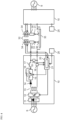
- arc welding device 10 performs welding alternately and repeatedly including a short-circuit period provided with a short-circuit state where welding wire 34 serving as a consumable electrode and base material 35 serving as an object to be welded are short-circuited, and an arc period provided with an arc state where an arc is generated between welding wire 34 and base material 35.
- Arc welding device 10 includes first rectifier 11, first switching unit 12, transformer 13, second rectifier 14, second switching unit 15, resistor 16, reactor 17, welding current detector 18, welding voltage detector 19, and controller 20.
- First rectifier 11 rectifies an input voltage input from input power source S outside arc welding device 10.
- First switching unit 12 adjusts output of first rectifier 11 by switching operation.
- Transformer 13 converts output of first switching unit 12 into output suitable for welding.
- Second rectifier 14 rectifies output of transformer 13.
- Second switching unit 15 adjusts output of second rectifier 14 by switching operation.
- Resistor 16 is connected in parallel with second switching unit 15.
- Reactor 17 is connected in series with second switching unit 15. Reactor 17 smooths output of second switching unit 15.
- Welding current detector 18 detects a welding current supplied through welding wire 34 and base material 35. A detection signal indicating the welding current detected by welding current detector 18 is transmitted to controller 20.
- Welding voltage detector 19 detects a welding voltage supplied across welding wire 34 and base material 35. A detection signal indicating the welding voltage detected by welding voltage detector 19 is transmitted to controller 20.
- Welding torch 30, base material 35, wire feeder 32, and setting unit 25 are connected to arc welding device 10 to constitute an arc welding system.
- Welding torch 30 is provided with welding tip 31 for supplying power to welding wire 34.
- wire feeder 32 performs feeding control for feeding welding wire 34, such as constant feeding control at a predetermined feeding speed, or feeding control for alternately performing forward feeding for feeding welding wire 34 in a direction to base material 35 and reverse feeding for feeding welding wire 34 in a direction opposite to the direction of the forward feeding.
- the welding is performed by alternately generating the short-circuit state and the arc state while alternately repeating the forward feeding and the reverse feeding as feeding of welding wire 34. This causes the forward feeding and the reverse feeding to be periodically performed so that the short-circuit state and the arc state are mechanically generated alternately.
- Switching between the forward feeding and the reverse feeding may be performed in accordance with a state of a welding phenomenon without performing periodical switching between the forward feeding and the reverse feeding.
- the reverse feeding is performed when welding wire 34 and base material 35 are short-circuited to cause the short-circuit state
- the forward feeding is performed when the short-circuit is opened to cause the arc state.
- Setting unit 25 is used for setting welding conditions in arc welding device 10.
- Welding output of arc welding device 10 is supplied to welding wire 34 through welding tip 31.
- the welding output of arc welding device 10 then causes arc 36 to be generated between welding wire 34 and base material 35 to perform welding.
- Controller 20 transmits signals between respective units of arc welding device 10 and devices outside arc welding device 10.
- the respective units of arc welding device 10 are first switching unit 12, second switching unit 15, welding current detector 18, and welding voltage detector 19.
- the devices outside arc welding device 10 are wire feeder 32 and setting unit 25.
- Controller 20 outputs control signals to first switching unit 12 and second switching unit 15 to control the welding output. Controller 20 outputs a control signal to wire feeder 32 to control wire feeding speed.
- Controller 20 includes a processor and a memory that is electrically connected to the processor and stores programs and information for operating the processor. Controller 20 includes calculation unit 21.
- Calculation unit 21 calculates an integrated power value by integrating power supplied to welding wire 34 within the predetermined period, after welding wire 34 is short-circuited.
- the power supplied to the welding wire is calculated based on the product of the welding current and the welding voltage.
- Controller 20 compares the welding voltage detected by welding voltage detector 19 with a threshold voltage that is preset. When the welding voltage is equal to or lower than the threshold voltage, controller 20 determines the short-circuit state. In contrast, when the welding voltage exceeds the threshold voltage, controller 20 determines the arc state.
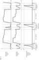
- controller 20 when determining the short-circuit state at time t1, controller 20 reduces the welding current to an initial current by adjusting the output of first switching unit 12. At this time, second switching unit 15 is continuously maintained in a conductive state.
- controller 20 adjusts the output of first switching unit 12 to increase the welding current at a predetermined rate of current increase from time t2 to time t3.
- operation of wire feeder 32 is controlled to reversely feed welding wire 34.
- welding wire 34 may be reversely fed with elapse of a predetermined time after being short-circuited (after the short-circuit is stabilized).
- opening of the short-circuit between welding wire 34 and base material 35 can be promoted.
- the feeding control for the forward feeding and the reverse feeding of welding wire 34 may not be performed.
- control for constant feeding at a predetermined feeding speed without reversely feeding welding wire 34 may be performed.
- Calculation unit 21 calculates the integrated power value by integrating power from time t2 to time t4. Specifically, the calculation of the integrated power value is started after the welding current starts to increase after welding wire 34 has been short-circuited. For example, when an increase in the welding current is detected, calculation unit 21 starts to calculate the integrated power value upon the detection. Instead of this, for example, when elapse of time during which the welding current is expected to increase is detected, calculation unit 21 starts to calculate the integrated power value upon the detection.
- the calculation of the integrated power value may be started after a predetermined time elapses after welding wire 34 has been short-circuited, for example, after the short-circuit is stabilized. For example, the calculation of the integrated power value may be started between time t1 and time t2. When the elapse of the predetermined time is detected, calculation unit 21 may start the calculation of the integrated power value upon the detection.
- Controller 20 determines whether the integrated power value is larger than threshold P predetermined. In the example illustrated in FIG. 2 , the integrated power value is larger than threshold P at time t3. When the integrated power value is larger than predetermined threshold P, controller 20 reduces the welding current to be supplied to welding wire 34 by switching a state of second switching unit 15 from the conductive state to an interrupted state.
- Controller 20 adjusts the output of first switching unit 12 such that the welding current becomes a predetermined current.
- second switching unit 15 is continuously maintained in a conductive state. Then, at time t4, the short circuit is opened and the state shifts to the arc state.
- integration of the integrated power value is terminated after the integrated power value is reset at a time point at which the integrated power value exceeds threshold P during the short-circuit period.
- the integration is terminated after the integrated power value is reset in arc determination for determining the arc state.
- arc welding device 10 is configured such that the amount of heat input to welding wire 34 is reduced by reducing the welding current before opening of the short-circuit based on the integrated amount of power supplied to welding wire 34. This enables reducing occurrence of spatters at the time of opening the short-circuit.
- the integrated current value indicates three peak values P1, P2, and P3.
- P1 being the largest integrated current value is defined as a threshold
- integrated current values being P2 and P3 are below threshold P1.
- controller 20 does not reduce the welding current to be supplied to welding wire 34 at the time when the integrated current value becomes P2 or P3.
- the integrated power value is larger than threshold P.
- the amount of heat input at the time of opening the short-circuit increases to generate spatters.
- controller 20 reduces the welding current at timing when the amount of heat input is unnecessary to be reduced before the time at which the integrated current value becomes P1 or P2, thereby varying the amount of heat input.
- a plurality of arc welding devices 10 is provided (two in the example illustrated in FIG. 4 ).
- Two arc welding devices 10 each include a ground-side cable connected to one base material 35.
- welding is performed by the plurality of arc welding devices 10 on common base material 35 electrically connected or base material 35 on a common jig (not illustrated). This causes two arc welding devices 10 to simultaneously generate arc 36.
- Arc welding device 10 of the present exemplary embodiment is configured such that the welding current at the time of opening the short circuit is reduced based on the integrated value of power supplied to welding wire 34, i.e., the amount of heat input actually applied to welding wire 34.
- the present invention is extremely useful and has high industrial applicability because it can obtain a highly practical effect of enabling occurrence of spatters at the time of opening a short-circuit to be reduced.
Landscapes
- Engineering & Computer Science (AREA)
- Physics & Mathematics (AREA)
- Plasma & Fusion (AREA)
- Mechanical Engineering (AREA)
- Theoretical Computer Science (AREA)
- Arc Welding Control (AREA)
Claims (8)
- Lichtbogenschweißverfahren, das das abwechselnde Wiederholen einer Kurzschlussperiode, die mit einem Kurzschlusszustand versehen ist, in dem ein Schweißdraht (34) und ein Basismaterial (35) kurzgeschlossen werden, und einer Lichtbogenperiode, die mit einem Lichtbogenzustand versehen ist, in dem zwischen dem Schweißdraht (34) und dem Basismaterial (35) ein Lichtbogen erzeugt wird, beinhaltet, wobei das Lichtbogenschweißverfahren durch die folgenden Schritte gekennzeichnet ist:a) Berechnen eines integrierten Leistungswertes durch Integrieren einer Leistung, die dem Schweißdraht (34) in einer vorbestimmten Periode zugeführt wird, in der ein Schweißstrom mit einer vorbestimmten Rate der Stromerhöhung erhöht wird, nachdem der Schweißdraht (34) kurzgeschlossen wurde;b) Reduzieren eines Schweißstroms, der dem Schweißdraht (34) zuzuführen ist, wenn der integrierte Leistungswert in der Kurzschlussperiode größer ist als ein vorbestimmter Schwellwert (P); undc) Beenden der Integration des integrierten Leistungswertes, nachdem der integrierte Leistungswert zum Bestimmen des Lichtbogenzustands in eine Lichtbogenbestimmung zurückgesetzt wurde, wenn der integrierte Leistungswert den vorbestimmten Schwellwert (P) nicht überschreitet.
- Lichtbogenschweißverfahren nach Anspruch 1, wobei in Schritt a) eine Berechnung des integrierten Leistungswertes gestartet wird, nachdem eine vorbestimmte Zeit vergangen ist, nachdem der Schweißdraht (34) kurzgeschlossen wurde.
- Lichtbogenschweißverfahren nach Anspruch 1 oder 2, wobei in Schritt a) die Berechnung des integrierten Leistungswertes gestartet wird, nachdem eine Erhöhung des Schweißstroms gestartet wurde, nachdem der Schweißdraht (34) kurzgeschlossen wurde.
- Lichtbogenschweißverfahren nach einem der Ansprüche 1 bis 3, das ferner den Schritt des umgekehrten Zuführens des Schweißdrahtes (34) umfasst, nachdem eine Erhöhung des Schweißstroms gestartet wurde, nachdem der Schweißdraht kurzgeschlossen wurde, oder nachdem eine vorbestimmte Zeit vergangen ist, nachdem der Schweißdraht (34) kurzgeschlossen wurde.
- Lichtbogenschweißverfahren nach Anspruch 1, das ferner den Schritt des Bestimmens, ob der integrierte Leistungswert größer ist als ein vorbestimmter Schwellwert (P), umfasst,
wobei der vorbestimmte Schwellwert (P) ein fester Wert ist. - Lichtbogenschweißvorrichtung (10), die ein Schweißen durchführt, das das abwechselnde Wiederholen einer Kurzschlussperiode, die mit einem Kurzschlusszustand versehen ist, in dem ein Schweißdraht (34) und ein Basismaterial (35) kurzgeschlossen werden, und einer Lichtbogenperiode, die mit einem Lichtbogenzustand versehen ist, in dem zwischen dem Schweißdraht (34) und dem Basismaterial (35) ein Lichtbogen erzeugt wird, beinhaltet, wobei die Lichtbogenschweißvorrichtung (10) durch Umfassen von Folgendem gekennzeichnet ist:eine Berechnungseinheit (21), die durch Integrieren einer Leistung, die dem Schweißdraht (34) in einer vorbestimmten Periode zugeführt wird, in der ein Schweißstrom mit einer vorbestimmten Rate der Stromerhöhung erhöht wird, nachdem der Schweißdraht (34) kurzgeschlossen wurde, einen integrierten Leistungswert berechnet, undeine Steuerung (20), die einen dem Schweißdraht (34) zuzuführenden Schweißstrom reduziert, wenn der integrierte Leistungswert in der Kurzschlussperiode größer ist als ein vorbestimmter Schwellwert (P), und eine Integration des integrierten Leistungswertes beendet, nachdem der integrierte Leistungswert zum Bestimmen des Lichtbogenzustands in eine Lichtbogenbestimmung zurückgesetzt wurde, wenn der integrierte Leistungswert den vorbestimmten Schwellwert (P) nicht überschreitet.
- Lichtbogenschweißvorrichtung (10) nach Anspruch 6, die eine Vielzahl der Lichtbogenschweißvorrichtungen (10) umfasst,
wobei Kabel auf einer Bodenseite in der Vielzahl von Lichtbogenschweißvorrichtungen (10) jeweils mit dem Basismaterial (35) verbunden sind. - Lichtbogenschweißvorrichtung (10) nach Anspruch 6, wobeidie Steuerung (20) ferner bestimmt, ob der integrierte Leistungswert größer ist als der vorbestimmte Schwellwert (P), undder vorbestimmte Schwellwert (P) ein fester Wert ist.
Applications Claiming Priority (2)
| Application Number | Priority Date | Filing Date | Title |
|---|---|---|---|
| JP2019096140 | 2019-05-22 | ||
| PCT/JP2020/017615 WO2020235293A1 (ja) | 2019-05-22 | 2020-04-24 | アーク溶接方法及びアーク溶接装置 |
Publications (3)
| Publication Number | Publication Date |
|---|---|
| EP3974093A1 EP3974093A1 (de) | 2022-03-30 |
| EP3974093A4 EP3974093A4 (de) | 2022-12-21 |
| EP3974093B1 true EP3974093B1 (de) | 2024-05-29 |
Family
ID=73458090
Family Applications (1)
| Application Number | Title | Priority Date | Filing Date |
|---|---|---|---|
| EP20810279.8A Active EP3974093B1 (de) | 2019-05-22 | 2020-04-24 | Lichtbogenschweissverfahren und lichtbogenschweissvorrichtung |
Country Status (5)
| Country | Link |
|---|---|
| US (1) | US20220055135A1 (de) |
| EP (1) | EP3974093B1 (de) |
| JP (2) | JP7499433B2 (de) |
| CN (1) | CN113891772B (de) |
| WO (1) | WO2020235293A1 (de) |
Families Citing this family (2)
| Publication number | Priority date | Publication date | Assignee | Title |
|---|---|---|---|---|
| US12521811B2 (en) * | 2021-11-10 | 2026-01-13 | Lincoln Global, Inc. | Welding or additive manufacturing system with discontinuous electrode feeding |
| WO2024034363A1 (ja) * | 2022-08-08 | 2024-02-15 | パナソニックIpマネジメント株式会社 | アーク溶接方法 |
Family Cites Families (12)
| Publication number | Priority date | Publication date | Assignee | Title |
|---|---|---|---|---|
| JPS5970469A (ja) * | 1982-10-14 | 1984-04-20 | Mitsubishi Electric Corp | 直流ア−ク溶接装置 |
| US6703579B1 (en) * | 2002-09-30 | 2004-03-09 | Cinetic Automation Corporation | Arc control for spraying |
| JP4661164B2 (ja) * | 2004-10-26 | 2011-03-30 | パナソニック株式会社 | 消耗電極式アーク溶接装置 |
| JP4760053B2 (ja) | 2005-02-28 | 2011-08-31 | パナソニック株式会社 | アーク溶接装置の制御方法およびアーク溶接装置 |
| JP2010214399A (ja) * | 2009-03-16 | 2010-09-30 | Daihen Corp | アーク溶接方法 |
| JP5840921B2 (ja) * | 2011-11-04 | 2016-01-06 | 株式会社ダイヘン | 消耗電極アーク溶接のくびれ検出制御方法 |
| US10040142B2 (en) * | 2013-03-15 | 2018-08-07 | Lincoln Global, Inc. | Variable polarity pulse with constant droplet size |
| US11014186B2 (en) * | 2014-02-14 | 2021-05-25 | Panasonic Intellectual Property Management Co., Ltd. | Wire fed arc welding method having abnormal arc or abnormal short circuit welding steps |
| US10052707B2 (en) * | 2014-04-04 | 2018-08-21 | Lincoln Global, Inc. | Method and system to use AC welding waveform and enhanced consumable to improve welding of galvanized workpiece |
| JP6341610B2 (ja) * | 2014-09-22 | 2018-06-13 | 株式会社ダイヘン | アーク溶接制御方法 |
| CN107921565B (zh) * | 2015-09-03 | 2019-10-11 | 松下知识产权经营株式会社 | 电弧焊接方法以及电弧焊接装置 |
| US11691212B2 (en) * | 2015-09-30 | 2023-07-04 | Daihen Corporation | Arc welding apparatus and arc welding method |
-
2020
- 2020-04-24 EP EP20810279.8A patent/EP3974093B1/de active Active
- 2020-04-24 CN CN202080036730.0A patent/CN113891772B/zh active Active
- 2020-04-24 WO PCT/JP2020/017615 patent/WO2020235293A1/ja not_active Ceased
- 2020-04-24 JP JP2021520668A patent/JP7499433B2/ja active Active
-
2021
- 2021-11-08 US US17/520,770 patent/US20220055135A1/en active Pending
-
2024
- 2024-05-13 JP JP2024078284A patent/JP7742530B2/ja active Active
Also Published As
| Publication number | Publication date |
|---|---|
| CN113891772B (zh) | 2023-10-24 |
| WO2020235293A1 (ja) | 2020-11-26 |
| EP3974093A4 (de) | 2022-12-21 |
| JP7499433B2 (ja) | 2024-06-14 |
| JP7742530B2 (ja) | 2025-09-22 |
| JPWO2020235293A1 (de) | 2020-11-26 |
| JP2024099058A (ja) | 2024-07-24 |
| EP3974093A1 (de) | 2022-03-30 |
| US20220055135A1 (en) | 2022-02-24 |
| CN113891772A (zh) | 2022-01-04 |
Similar Documents
| Publication | Publication Date | Title |
|---|---|---|
| US9616514B2 (en) | System and method to detect droplet detachment | |
| KR102124223B1 (ko) | 펄스 아크 용접의 출력 제어 방법 | |
| US9333581B2 (en) | Apparatus and method for energy replacement in a welding waveform during welding | |
| US20220055136A1 (en) | Arc welding method and arc welding device | |
| JP2006334601A (ja) | パルスアーク溶接制御方法及びパルスアーク溶接装置 | |
| JP7742530B2 (ja) | アーク溶接方法及びアーク溶接装置 | |
| US20160346864A1 (en) | Arc welding method | |
| US12220772B2 (en) | Arc welding control method and arc welding device | |
| KR20200116058A (ko) | 아크 용접 회로의 실시간 저항 모니터링 | |
| US9615404B2 (en) | Consumable electrode arc welding method | |
| JP4815966B2 (ja) | アーク溶接システム | |
| JP7556681B2 (ja) | 時間に基づく短絡応答 | |
| JP5871360B2 (ja) | 消耗電極アーク溶接のくびれ検出制御方法 | |
| JP2022091176A (ja) | 消耗電極アーク溶接のくびれ検出制御方法 | |
| EP3974092B1 (de) | Lichtbogenschweissverfahren | |
| JP2005288540A (ja) | くびれ検出時電流急減機能付溶接電源及び溶接装置 | |
| JP2020082195A (ja) | スパッタを低減するためのアーク溶接システム制御方法 | |
| JPH0557071B2 (de) | ||
| JP2026016906A (ja) | アーク溶接方法及びアーク溶接制御プログラム | |
| JP2014039951A (ja) | 消耗電極アーク溶接制御方法 | |
| JP2020062667A (ja) | 消耗電極アーク溶接のくびれ検出制御方法 | |
| JP7108368B2 (ja) | 溶接電源のくびれ検出制御方法 |
Legal Events
| Date | Code | Title | Description |
|---|---|---|---|
| STAA | Information on the status of an ep patent application or granted ep patent |
Free format text: STATUS: THE INTERNATIONAL PUBLICATION HAS BEEN MADE |
|
| PUAI | Public reference made under article 153(3) epc to a published international application that has entered the european phase |
Free format text: ORIGINAL CODE: 0009012 |
|
| STAA | Information on the status of an ep patent application or granted ep patent |
Free format text: STATUS: REQUEST FOR EXAMINATION WAS MADE |
|
| 17P | Request for examination filed |
Effective date: 20211108 |
|
| AK | Designated contracting states |
Kind code of ref document: A1 Designated state(s): AL AT BE BG CH CY CZ DE DK EE ES FI FR GB GR HR HU IE IS IT LI LT LU LV MC MK MT NL NO PL PT RO RS SE SI SK SM TR |
|
| DAV | Request for validation of the european patent (deleted) | ||
| DAX | Request for extension of the european patent (deleted) | ||
| A4 | Supplementary search report drawn up and despatched |
Effective date: 20221122 |
|
| RIC1 | Information provided on ipc code assigned before grant |
Ipc: B23K 26/12 20140101ALI20221116BHEP Ipc: B23K 9/12 20060101ALI20221116BHEP Ipc: B23K 9/073 20060101AFI20221116BHEP |
|
| RIC1 | Information provided on ipc code assigned before grant |
Ipc: B23K 9/173 20060101ALI20231029BHEP Ipc: B23K 9/095 20060101ALI20231029BHEP Ipc: B23K 9/09 20060101ALI20231029BHEP Ipc: B23K 9/073 20060101AFI20231029BHEP |
|
| GRAP | Despatch of communication of intention to grant a patent |
Free format text: ORIGINAL CODE: EPIDOSNIGR1 |
|
| STAA | Information on the status of an ep patent application or granted ep patent |
Free format text: STATUS: GRANT OF PATENT IS INTENDED |
|
| INTG | Intention to grant announced |
Effective date: 20240108 |
|
| GRAS | Grant fee paid |
Free format text: ORIGINAL CODE: EPIDOSNIGR3 |
|
| GRAA | (expected) grant |
Free format text: ORIGINAL CODE: 0009210 |
|
| STAA | Information on the status of an ep patent application or granted ep patent |
Free format text: STATUS: THE PATENT HAS BEEN GRANTED |
|
| AK | Designated contracting states |
Kind code of ref document: B1 Designated state(s): AL AT BE BG CH CY CZ DE DK EE ES FI FR GB GR HR HU IE IS IT LI LT LU LV MC MK MT NL NO PL PT RO RS SE SI SK SM TR |
|
| REG | Reference to a national code |
Ref country code: CH Ref legal event code: EP |
|
| REG | Reference to a national code |
Ref country code: IE Ref legal event code: FG4D |
|
| REG | Reference to a national code |
Ref country code: DE Ref legal event code: R096 Ref document number: 602020031753 Country of ref document: DE |
|
| REG | Reference to a national code |
Ref country code: LT Ref legal event code: MG9D |
|
| REG | Reference to a national code |
Ref country code: NL Ref legal event code: MP Effective date: 20240529 |
|
| PG25 | Lapsed in a contracting state [announced via postgrant information from national office to epo] |
Ref country code: IS Free format text: LAPSE BECAUSE OF FAILURE TO SUBMIT A TRANSLATION OF THE DESCRIPTION OR TO PAY THE FEE WITHIN THE PRESCRIBED TIME-LIMIT Effective date: 20240929 |
|
| PG25 | Lapsed in a contracting state [announced via postgrant information from national office to epo] |
Ref country code: BG Free format text: LAPSE BECAUSE OF FAILURE TO SUBMIT A TRANSLATION OF THE DESCRIPTION OR TO PAY THE FEE WITHIN THE PRESCRIBED TIME-LIMIT Effective date: 20240529 |
|
| PG25 | Lapsed in a contracting state [announced via postgrant information from national office to epo] |
Ref country code: HR Free format text: LAPSE BECAUSE OF FAILURE TO SUBMIT A TRANSLATION OF THE DESCRIPTION OR TO PAY THE FEE WITHIN THE PRESCRIBED TIME-LIMIT Effective date: 20240529 Ref country code: FI Free format text: LAPSE BECAUSE OF FAILURE TO SUBMIT A TRANSLATION OF THE DESCRIPTION OR TO PAY THE FEE WITHIN THE PRESCRIBED TIME-LIMIT Effective date: 20240529 |
|
| PG25 | Lapsed in a contracting state [announced via postgrant information from national office to epo] |
Ref country code: GR Free format text: LAPSE BECAUSE OF FAILURE TO SUBMIT A TRANSLATION OF THE DESCRIPTION OR TO PAY THE FEE WITHIN THE PRESCRIBED TIME-LIMIT Effective date: 20240830 |
|
| REG | Reference to a national code |
Ref country code: AT Ref legal event code: MK05 Ref document number: 1690228 Country of ref document: AT Kind code of ref document: T Effective date: 20240529 |
|
| PG25 | Lapsed in a contracting state [announced via postgrant information from national office to epo] |
Ref country code: ES Free format text: LAPSE BECAUSE OF FAILURE TO SUBMIT A TRANSLATION OF THE DESCRIPTION OR TO PAY THE FEE WITHIN THE PRESCRIBED TIME-LIMIT Effective date: 20240529 |
|
| PG25 | Lapsed in a contracting state [announced via postgrant information from national office to epo] |
Ref country code: AT Free format text: LAPSE BECAUSE OF FAILURE TO SUBMIT A TRANSLATION OF THE DESCRIPTION OR TO PAY THE FEE WITHIN THE PRESCRIBED TIME-LIMIT Effective date: 20240529 |
|
| PG25 | Lapsed in a contracting state [announced via postgrant information from national office to epo] |
Ref country code: PL Free format text: LAPSE BECAUSE OF FAILURE TO SUBMIT A TRANSLATION OF THE DESCRIPTION OR TO PAY THE FEE WITHIN THE PRESCRIBED TIME-LIMIT Effective date: 20240529 |
|
| PG25 | Lapsed in a contracting state [announced via postgrant information from national office to epo] |
Ref country code: LV Free format text: LAPSE BECAUSE OF FAILURE TO SUBMIT A TRANSLATION OF THE DESCRIPTION OR TO PAY THE FEE WITHIN THE PRESCRIBED TIME-LIMIT Effective date: 20240529 |
|
| PG25 | Lapsed in a contracting state [announced via postgrant information from national office to epo] |
Ref country code: PL Free format text: LAPSE BECAUSE OF FAILURE TO SUBMIT A TRANSLATION OF THE DESCRIPTION OR TO PAY THE FEE WITHIN THE PRESCRIBED TIME-LIMIT Effective date: 20240529 Ref country code: NO Free format text: LAPSE BECAUSE OF FAILURE TO SUBMIT A TRANSLATION OF THE DESCRIPTION OR TO PAY THE FEE WITHIN THE PRESCRIBED TIME-LIMIT Effective date: 20240829 Ref country code: LV Free format text: LAPSE BECAUSE OF FAILURE TO SUBMIT A TRANSLATION OF THE DESCRIPTION OR TO PAY THE FEE WITHIN THE PRESCRIBED TIME-LIMIT Effective date: 20240529 Ref country code: IS Free format text: LAPSE BECAUSE OF FAILURE TO SUBMIT A TRANSLATION OF THE DESCRIPTION OR TO PAY THE FEE WITHIN THE PRESCRIBED TIME-LIMIT Effective date: 20240929 Ref country code: HR Free format text: LAPSE BECAUSE OF FAILURE TO SUBMIT A TRANSLATION OF THE DESCRIPTION OR TO PAY THE FEE WITHIN THE PRESCRIBED TIME-LIMIT Effective date: 20240529 Ref country code: GR Free format text: LAPSE BECAUSE OF FAILURE TO SUBMIT A TRANSLATION OF THE DESCRIPTION OR TO PAY THE FEE WITHIN THE PRESCRIBED TIME-LIMIT Effective date: 20240830 Ref country code: FI Free format text: LAPSE BECAUSE OF FAILURE TO SUBMIT A TRANSLATION OF THE DESCRIPTION OR TO PAY THE FEE WITHIN THE PRESCRIBED TIME-LIMIT Effective date: 20240529 Ref country code: ES Free format text: LAPSE BECAUSE OF FAILURE TO SUBMIT A TRANSLATION OF THE DESCRIPTION OR TO PAY THE FEE WITHIN THE PRESCRIBED TIME-LIMIT Effective date: 20240529 Ref country code: BG Free format text: LAPSE BECAUSE OF FAILURE TO SUBMIT A TRANSLATION OF THE DESCRIPTION OR TO PAY THE FEE WITHIN THE PRESCRIBED TIME-LIMIT Effective date: 20240529 Ref country code: AT Free format text: LAPSE BECAUSE OF FAILURE TO SUBMIT A TRANSLATION OF THE DESCRIPTION OR TO PAY THE FEE WITHIN THE PRESCRIBED TIME-LIMIT Effective date: 20240529 Ref country code: RS Free format text: LAPSE BECAUSE OF FAILURE TO SUBMIT A TRANSLATION OF THE DESCRIPTION OR TO PAY THE FEE WITHIN THE PRESCRIBED TIME-LIMIT Effective date: 20240829 |
|
| PG25 | Lapsed in a contracting state [announced via postgrant information from national office to epo] |
Ref country code: NL Free format text: LAPSE BECAUSE OF FAILURE TO SUBMIT A TRANSLATION OF THE DESCRIPTION OR TO PAY THE FEE WITHIN THE PRESCRIBED TIME-LIMIT Effective date: 20240529 |
|
| PG25 | Lapsed in a contracting state [announced via postgrant information from national office to epo] |
Ref country code: NL Free format text: LAPSE BECAUSE OF FAILURE TO SUBMIT A TRANSLATION OF THE DESCRIPTION OR TO PAY THE FEE WITHIN THE PRESCRIBED TIME-LIMIT Effective date: 20240529 |
|
| PG25 | Lapsed in a contracting state [announced via postgrant information from national office to epo] |
Ref country code: DK Free format text: LAPSE BECAUSE OF FAILURE TO SUBMIT A TRANSLATION OF THE DESCRIPTION OR TO PAY THE FEE WITHIN THE PRESCRIBED TIME-LIMIT Effective date: 20240529 |
|
| PG25 | Lapsed in a contracting state [announced via postgrant information from national office to epo] |
Ref country code: EE Free format text: LAPSE BECAUSE OF FAILURE TO SUBMIT A TRANSLATION OF THE DESCRIPTION OR TO PAY THE FEE WITHIN THE PRESCRIBED TIME-LIMIT Effective date: 20240529 |
|
| PG25 | Lapsed in a contracting state [announced via postgrant information from national office to epo] |
Ref country code: CZ Free format text: LAPSE BECAUSE OF FAILURE TO SUBMIT A TRANSLATION OF THE DESCRIPTION OR TO PAY THE FEE WITHIN THE PRESCRIBED TIME-LIMIT Effective date: 20240529 |
|
| PG25 | Lapsed in a contracting state [announced via postgrant information from national office to epo] |
Ref country code: SK Free format text: LAPSE BECAUSE OF FAILURE TO SUBMIT A TRANSLATION OF THE DESCRIPTION OR TO PAY THE FEE WITHIN THE PRESCRIBED TIME-LIMIT Effective date: 20240529 Ref country code: RO Free format text: LAPSE BECAUSE OF FAILURE TO SUBMIT A TRANSLATION OF THE DESCRIPTION OR TO PAY THE FEE WITHIN THE PRESCRIBED TIME-LIMIT Effective date: 20240529 |
|
| PG25 | Lapsed in a contracting state [announced via postgrant information from national office to epo] |
Ref country code: SM Free format text: LAPSE BECAUSE OF FAILURE TO SUBMIT A TRANSLATION OF THE DESCRIPTION OR TO PAY THE FEE WITHIN THE PRESCRIBED TIME-LIMIT Effective date: 20240529 |
|
| PG25 | Lapsed in a contracting state [announced via postgrant information from national office to epo] |
Ref country code: SM Free format text: LAPSE BECAUSE OF FAILURE TO SUBMIT A TRANSLATION OF THE DESCRIPTION OR TO PAY THE FEE WITHIN THE PRESCRIBED TIME-LIMIT Effective date: 20240529 Ref country code: SK Free format text: LAPSE BECAUSE OF FAILURE TO SUBMIT A TRANSLATION OF THE DESCRIPTION OR TO PAY THE FEE WITHIN THE PRESCRIBED TIME-LIMIT Effective date: 20240529 Ref country code: RO Free format text: LAPSE BECAUSE OF FAILURE TO SUBMIT A TRANSLATION OF THE DESCRIPTION OR TO PAY THE FEE WITHIN THE PRESCRIBED TIME-LIMIT Effective date: 20240529 Ref country code: EE Free format text: LAPSE BECAUSE OF FAILURE TO SUBMIT A TRANSLATION OF THE DESCRIPTION OR TO PAY THE FEE WITHIN THE PRESCRIBED TIME-LIMIT Effective date: 20240529 Ref country code: DK Free format text: LAPSE BECAUSE OF FAILURE TO SUBMIT A TRANSLATION OF THE DESCRIPTION OR TO PAY THE FEE WITHIN THE PRESCRIBED TIME-LIMIT Effective date: 20240529 Ref country code: CZ Free format text: LAPSE BECAUSE OF FAILURE TO SUBMIT A TRANSLATION OF THE DESCRIPTION OR TO PAY THE FEE WITHIN THE PRESCRIBED TIME-LIMIT Effective date: 20240529 |
|
| PG25 | Lapsed in a contracting state [announced via postgrant information from national office to epo] |
Ref country code: IT Free format text: LAPSE BECAUSE OF FAILURE TO SUBMIT A TRANSLATION OF THE DESCRIPTION OR TO PAY THE FEE WITHIN THE PRESCRIBED TIME-LIMIT Effective date: 20240529 |
|
| REG | Reference to a national code |
Ref country code: DE Ref legal event code: R097 Ref document number: 602020031753 Country of ref document: DE |
|
| PLBE | No opposition filed within time limit |
Free format text: ORIGINAL CODE: 0009261 |
|
| STAA | Information on the status of an ep patent application or granted ep patent |
Free format text: STATUS: NO OPPOSITION FILED WITHIN TIME LIMIT |
|
| PG25 | Lapsed in a contracting state [announced via postgrant information from national office to epo] |
Ref country code: SI Free format text: LAPSE BECAUSE OF FAILURE TO SUBMIT A TRANSLATION OF THE DESCRIPTION OR TO PAY THE FEE WITHIN THE PRESCRIBED TIME-LIMIT Effective date: 20240529 |
|
| 26N | No opposition filed |
Effective date: 20250303 |
|
| PG25 | Lapsed in a contracting state [announced via postgrant information from national office to epo] |
Ref country code: SE Free format text: LAPSE BECAUSE OF FAILURE TO SUBMIT A TRANSLATION OF THE DESCRIPTION OR TO PAY THE FEE WITHIN THE PRESCRIBED TIME-LIMIT Effective date: 20240529 |
|
| REG | Reference to a national code |
Ref country code: CH Ref legal event code: H13 Free format text: ST27 STATUS EVENT CODE: U-0-0-H10-H13 (AS PROVIDED BY THE NATIONAL OFFICE) Effective date: 20251125 |
|
| PG25 | Lapsed in a contracting state [announced via postgrant information from national office to epo] |
Ref country code: LU Free format text: LAPSE BECAUSE OF NON-PAYMENT OF DUE FEES Effective date: 20250424 |
|
| PG25 | Lapsed in a contracting state [announced via postgrant information from national office to epo] |
Ref country code: MC Free format text: LAPSE BECAUSE OF FAILURE TO SUBMIT A TRANSLATION OF THE DESCRIPTION OR TO PAY THE FEE WITHIN THE PRESCRIBED TIME-LIMIT Effective date: 20240529 |
|
| GBPC | Gb: european patent ceased through non-payment of renewal fee |
Effective date: 20250424 |
|
| REG | Reference to a national code |
Ref country code: BE Ref legal event code: MM Effective date: 20250430 |
|
| PG25 | Lapsed in a contracting state [announced via postgrant information from national office to epo] |
Ref country code: GB Free format text: LAPSE BECAUSE OF NON-PAYMENT OF DUE FEES Effective date: 20250424 |
|
| PG25 | Lapsed in a contracting state [announced via postgrant information from national office to epo] |
Ref country code: FR Free format text: LAPSE BECAUSE OF NON-PAYMENT OF DUE FEES Effective date: 20250430 |
|
| PG25 | Lapsed in a contracting state [announced via postgrant information from national office to epo] |
Ref country code: BE Free format text: LAPSE BECAUSE OF NON-PAYMENT OF DUE FEES Effective date: 20250430 |
|
| PG25 | Lapsed in a contracting state [announced via postgrant information from national office to epo] |
Ref country code: CH Free format text: LAPSE BECAUSE OF NON-PAYMENT OF DUE FEES Effective date: 20250430 |
|
| PG25 | Lapsed in a contracting state [announced via postgrant information from national office to epo] |
Ref country code: IE Free format text: LAPSE BECAUSE OF NON-PAYMENT OF DUE FEES Effective date: 20250424 |
|
| PG25 | Lapsed in a contracting state [announced via postgrant information from national office to epo] |
Ref country code: CY Free format text: LAPSE BECAUSE OF FAILURE TO SUBMIT A TRANSLATION OF THE DESCRIPTION OR TO PAY THE FEE WITHIN THE PRESCRIBED TIME-LIMIT Effective date: 20240529 |
|
| PG25 | Lapsed in a contracting state [announced via postgrant information from national office to epo] |
Ref country code: LT Free format text: LAPSE BECAUSE OF FAILURE TO SUBMIT A TRANSLATION OF THE DESCRIPTION OR TO PAY THE FEE WITHIN THE PRESCRIBED TIME-LIMIT Effective date: 20240529 |
|
| PG25 | Lapsed in a contracting state [announced via postgrant information from national office to epo] |
Ref country code: PT Free format text: LAPSE BECAUSE OF NON-PAYMENT OF DUE FEES Effective date: 20240529 |
|
| PGFP | Annual fee paid to national office [announced via postgrant information from national office to epo] |
Ref country code: DE Payment date: 20260422 Year of fee payment: 7 |