EP3972392B1 - Weicher röntgenstrahlenapparat zur beseitigung statischer elektrizität - Google Patents
Weicher röntgenstrahlenapparat zur beseitigung statischer elektrizität Download PDFInfo
- Publication number
- EP3972392B1 EP3972392B1 EP20804912.2A EP20804912A EP3972392B1 EP 3972392 B1 EP3972392 B1 EP 3972392B1 EP 20804912 A EP20804912 A EP 20804912A EP 3972392 B1 EP3972392 B1 EP 3972392B1
- Authority
- EP
- European Patent Office
- Prior art keywords
- soft
- ionized air
- ray
- sheet
- ray shielding
- Prior art date
- Legal status (The legal status is an assumption and is not a legal conclusion. Google has not performed a legal analysis and makes no representation as to the accuracy of the status listed.)
- Active
Links
Images


Classifications
-
- H—ELECTRICITY
- H05—ELECTRIC TECHNIQUES NOT OTHERWISE PROVIDED FOR
- H05F—STATIC ELECTRICITY; NATURALLY-OCCURRING ELECTRICITY
- H05F3/00—Carrying-off electrostatic charges
- H05F3/06—Carrying-off electrostatic charges by means of ionising radiation
-
- G—PHYSICS
- G21—NUCLEAR PHYSICS; NUCLEAR ENGINEERING
- G21F—PROTECTION AGAINST X-RADIATION, GAMMA RADIATION, CORPUSCULAR RADIATION OR PARTICLE BOMBARDMENT; TREATING RADIOACTIVELY CONTAMINATED MATERIAL; DECONTAMINATION ARRANGEMENTS THEREFOR
- G21F3/00—Shielding characterised by its physical form, e.g. granules, or shape of the material
-
- H—ELECTRICITY
- H01—ELECTRIC ELEMENTS
- H01T—SPARK GAPS; OVERVOLTAGE ARRESTERS USING SPARK GAPS; SPARKING PLUGS; CORONA DEVICES; GENERATING IONS TO BE INTRODUCED INTO NON-ENCLOSED GASES
- H01T23/00—Apparatus for generating ions to be introduced into non-enclosed gases, e.g. into the atmosphere
Definitions
- a static electricity removal apparatus that generates ions for preventing electric charging and removing static electricity on a substrate surface is installed in semiconductor, liquid crystal, and organic EL manufacturing apparatuses.
- the static electricity removal apparatus a corona discharge static electricity removal apparatus that ionizes air by high voltage and a soft X-ray static electricity removal apparatus that irradiates air with a soft X ray to ionize air are provided.
- Document WO2008023727 discloses a soft X-ray shielding sheet that includes a first external layer sheet having a supply opening for supplying ionized air, an intermediate layer sheet having an ionized air flow-in opening communicating with the supply opening; and a second external layer sheet having a discharge opening communicating with the ionized air passage.
- the sheets are overlaid on one another and boded.
- One or more ionized air passages 9 are provided to communicate with the supply opening, the ionized air passage, and the discharge opening.
- Document JPH076860 discloses an ion gas generator including a cylindrical body containing an inlet and a gas blowoff port of the gas, the cylindrical body, inlet a gas supply means for flowing gas from, provided on the air outlet of the tubular body, and a perforated plate having a plurality of fine through holes, the radiation and the gas of X-ray in the desired region of the tubular body inside which the gas has flowed, comprising an X-ray generating tube to ionize.
- Patent Literature 1 International Publication No. WO2008/023727
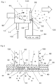
- a soft X-ray static electricity removal apparatus 1 includes, as illustrated in Figure 1 and Figure 2 for example, a soft X-ray generation device 90, a container 10, a soft X-ray shielding sheet 20, and an insulating layer 50.
- the soft X-ray generation device 90 generates soft X-rays 92 for ionizing air 102.
- the container 10 has an outlet 12 from which ionized air 100 that has been ionized by the soft X-rays 92 flows out.
- the ionized air passage 38 extending from the supply ports 32 to the discharge port 42 has a bent portion 39.
- the ionized air passage through which ionized air flows has the bent portions and this increases the number of times soft X-rays hit the ionized air passage during passing through the passage, thereby making the soft X-rays difficult to pass.
- the soft X-ray shielding sheet 20 has a circular cross section; and the insulating layer 50 has a plurality of arc-shaped ceramics 52 which are arranged so as to surround an outer periphery of the soft X-ray shielding sheet 20.
- the insulating layer has a plurality of arc shaped ceramics and this prevents deterioration due to soft X-rays and prevents cracks at both the time of manufacture and the time of use.
- a soft X-ray static electricity removal apparatus 1 further includes, as illustrated in Figure 1 for example, a power supply device 60 that applies a potential difference to the container 10 and the soft X-ray shielding sheet 20.
- a potential difference can be applied to the container and the soft X-ray shielding sheet and this allows adjustment of the amount of positive ions/negative ions.
- a soft X-ray static electricity removal apparatus 1 further includes, as illustrated in Figure 1 and Figure 5 for example, a casing 55 that holds the insulating layer 50 at the outlet 12 of the container 10 so as to have the insulating layer 50 and the soft X-ray shielding sheet 20 arranged at the outlet 12 and that has a gap 56 between itself and the soft X-ray shielding sheet 20.
- a casing 55 that holds the insulating layer 50 at the outlet 12 of the container 10 so as to have the insulating layer 50 and the soft X-ray shielding sheet 20 arranged at the outlet 12 and that has a gap 56 between itself and the soft X-ray shielding sheet 20.
- air can be ionized by soft X-rays, the soft X-rays can be shielded while allowing passage of the ionized air with the soft X-ray shielding sheet, and further the soft X-ray shielding sheet is insulated from the container.
- the amount of ionized air discharged can be increased.
- the amount of positive ions/negative ions discharged can be adjusted.
- the soft X-ray static electricity removal apparatus 1 includes a container 10 that provides a space in which air is ionized and through which ionized air 100, which has been ionized, flows.
- the container 10 has an air inlet 14 that takes air 102 into the container 10.
- the air inlet 14 may include a fan to forcibly take the air 102 outside the container 10 into the container 10.
- a soft X-ray generation device 90 is arranged near a position where the air inlet 14 is provided.
- Soft X-rays 92 are generated from the soft X-ray generation device 90 and air is irradiated therewith within the container 10; thereby the air is ionized.
- the soft X-ray generation device 90 may be a known soft X-ray device and thus, detailed description thereof is omitted.
- an outlet 12 for the ionized air 100 is formed at a position away from a position where the air inlet 14 is provided.
- air is caused to flow from the air inlet 14 to the outlet 12, the air can be ionized by the soft X-rays 92 from the soft X-ray generation device 90, and the ionized air 100 is discharged from the outlet in a short period of time.
- this arrangement is preferable; but other arrangements are acceptable.
- the container 10 is formed by stainless steel or other metal.
- a soft X-ray shielding sheet 20 is arranged. That is, the ionized air 100 is discharged from the container 10 by passing through the soft X-ray shielding sheet 20.
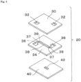
- FIG. 2 is a cross-sectional view in the vicinity of the ionized air transmission portion 44 of the soft X-ray shielding sheet 20; and Figure 3 is an exploded perspective view thereof.
- the soft X-ray shielding sheet 20 is formed by stacking and adhering three sheets of: a first outer sheet 30 that is formed of a material opaque to the soft X-rays 92, an interlayer sheet 34 that is formed of a material opaque to the soft X-rays 92, and a second outer sheet that is formed of a material opaque to the soft X-rays 92.
- the material opaque to soft X-rays is typically a metal such as lead, iron, or aluminum, but is not limited to the metal. Metal can block the transmission of soft X-rays 92 even if it is thin and in addition, it is easily formed to be thin, so it is suitable for the soft X-ray shielding sheet 20. Furthermore, a method for stacking and adhering them is not particularly limited.
- supply ports 32 through which the ionized air 100 in the container 10 enters the soft X-ray shielding sheet 20 are formed.
- an ionized air passage 38 that has an ionized air inlet opening 36 at both end parts thereof is formed.
- a discharge port 42 through which the ionized air 100 is discharged to the outside of the container 10 is formed.
- the ionized air passage 38 in the interlayer sheet 34 includes the ionized air inlet openings 36 which are respectively formed at positions where communication with the supply ports 32 in the first outer sheet 30 is performed; and is formed so as to communicate with each of the ionized air inlet openings 36.
- the discharge port 42 in the second outer sheet 40 is formed at a position where communication with the ionized air passage 38 is performed in the interlayer sheet 34.
- the supply ports 32 in the first outer sheet 30 and the ionized air inlet openings 36 in the interlayer sheet 34 are made to communicate with each other, respectively and furthermore, at the center of the ionized air passage 38 in the interlayer sheet 34, the ionized air passage 38 and the discharge port 42 in the second outer sheet 40 communicate with each other; thereby forming an ionized air transmission portion 44.
- one ionized air transmission portion 44 may be formed; however, a plurality of ionized air transmission portions 44 may be formed.
- bent portions 39 that bend at 90 degrees on a plane are provided so that the number of times the soft X-rays 92 hit an inner surface 41 of the second outer sheet 40 and an inner surface 31 of the first outer sheet 30 while entering from the supply ports 32 and reaching the discharge port 42 increases and the soft X-rays 92 are attenuated or disappear.
- each of the bent portions 39 of the ionized air passage 38 is formed to have a curved face 37 that is to reduce the fluid resistance of the ionized air. That is, the ionized air passage 38 has at least one or more bent portions 39 that bend at 90 degrees on a plane and thereby allows the soft X-rays 92 to disappear due to its hit on an inner surface, that is, the passage.
- the shape of the ionized air passage 38 may be other shapes. The shape is preferably such that the fluid resistance of the ionized air 100 is controlled while the number of times the soft X-rays 92 hit the passage is increased.
- the ionized air 100 which has been ionized into positive ions and negative ions by the soft X-rays 92 is in a pressurized state which is caused by feeding the air 102 into the container 10. Therefore, the ionized air 100 flows from the supply ports 32 through the ionized air inlet openings 36 and the ionized air passage 38 and is discharged from the discharge port 42 to a downstream side of the soft X-ray shielding sheet 20.
- the soft X-rays 92 are incident from each of the supply ports 32 and go straight, pass the ionized air passage 38 through the ionized air inlet openings 36, and reach the discharge port 42; during which as illustrated in Figure 2 , they hit the inner surface 41 of the second outer sheet 40, the inner surface 31 of the first outer sheet 30, the curved faces 37 of the bent portions 39, or the like, thereby preventing their travel in a straight line.
- the soft X-rays 92 are attenuated and eventually almost disappear, so that the dangerous soft X-rays 92 are prevented from leaking from the discharge port 42.
- the size and length of a cross section of the ionized air transmission portion 44 and the number of bent portions 39, that is, a path of the ionized air passage 38 and the like are designed. It should be noted that the number of sheets constituting the soft X-ray shielding sheet 20 may be not three but four or more.
- the ionized air 100 introduced from the supply ports 32 passes through the ionized air passage 38 and reaches the discharge port 42. Since the bent portions 39 of the ionized air passage 38, which are provided from the viewpoint of preventing leakage of the soft X-rays 92, are formed to have the curved face 37, the fluid resistance is reduced, allowing the ionized air 100 to reach the discharge port 42 in a short period of time. In particular, it is preferable that the ionized air 100 should pass through the soft X-ray shielding sheet 20 in a short period of time so as to prevent recombination of positive ions and negative ions; and thus, the path of the ionized air transmission portion 44 is shortened. Therefore, a large amount of ions are discharged to a downstream side of the discharge port 42.
- two supply ports 32 and one discharge port 42 are provided, where the ionized air 100 passes the ionized air passage 38 and two flows of it collide at the discharge port 42 and thereby, the ionized air 100 from the discharge port 42 can be made to blow out vertically.
- a conventional soft X-ray static electricity removal apparatus 201 the container 10 and the soft X-ray shielding sheet 20 are conducted to each other.
- a grounding wire 210 is connected to the container 10 so that a potential 212 from the container 10 and the soft X-ray shielding sheet 20 is passed to the ground.
- the ionized air 100 is trapped in the soft X-ray shielding sheet 20 and the amount of ionized air 100 that passes through the soft X-ray shielding sheet 20 is apt to decrease.
- the container 10 and the soft X-ray shielding sheet 20 are insulated from each other by the insulating layer 50.
- the soft X-ray shielding sheet 20 illustrated in Figure 4 has a circular cross section and has a number of ionized air transmission portions 44 formed therein. On a circular outer periphery thereof, the insulating layer 50 is arranged.
- Figure 5 illustrates one example of the insulating layer 50.
- the soft X-ray shielding sheet 20 On the circular outer periphery of the soft X-ray shielding sheet 20, three arc-shaped ceramics 52 are arranged. Although there are insulating materials such as plastic and the like other than ceramic, they deteriorate by being irradiated with soft X-rays and generate powders. Ceramic does not deteriorate even when being irradiated with soft X-rays and is therefore preferable. In addition, an annular-shaped ceramic that covers the outer periphery of the soft X-ray shielding sheet 20 is acceptable; however, ceramic is a fragile material and therefore, may be broken at the time of manufacture or use.
- the annular-shaped insulating layer 50 which covers the outer periphery of the soft X-ray shielding sheet 20, and from leaking, the annular-shaped insulating layer 50 is covered by a casing 55 (see Figure 6 ) of the soft X-ray shielding sheet 20.
- the casing 55 is commonly formed with the same material as that of the container 10, such as stainless steel.
- the casing 55 is structured so as to cover the soft X-ray shielding sheet 20 with a narrow gap 56 (for example, a clearance of 0.5 mm and a radial-direction width of 2 mm).
- a narrow gap 56 for example, a clearance of 0.5 mm and a radial-direction width of 2 mm.
- the gap 56 is made narrow and long, that is, the width in a radial direction is made larger than the clearance; and thereby, the soft X-rays 92 are prevented from passing through a space between the soft X-ray shielding sheet 20 and the casing 55.
- the gap 56 is shaped so that, when the soft X-rays 92 pass through the gap 56, they hit the soft X-ray shielding sheet 20 and the casing 55 three times or more.
- the soft X-rays 92 are prevented from traveling in a straight line and hit the casing 55 and around the outer periphery of the soft X-ray shielding sheet 20, thereby being attenuated and disappearing.
- the casing 55 of the soft X-ray shielding sheet 20 preferably, as illustrated in Figure 5 (a) , is a circular ring having a cross section of a U shape and is configured to store the arc-shaped ceramics 52 within the U shape, which facilitates handling the insulating layer 50.
- the arc-shaped ceramics 52 obtained by dividing its circumference into three equal parts are used; however, the number thereof is freely selected.
- the container 10 and the soft X-ray shielding sheet 20 are insulated from each other by the insulating layer 50 and thereby when ions are trapped in the soft X-ray shielding sheet 20 in an initial stage of operation, the soft X-ray shielding sheet 20 gets the potential of trapped ions (positive or negative) and thereafter, ions of the same potential are not trapped and are transmitted through the soft X-ray shielding sheet 20. Therefore, the ionized air 100 that is discharged through the soft X-ray shielding sheet 20 increases.
- a potential difference can be applied to the container 10 and the soft X-ray shielding sheet 20.
- a power supply device 60 is provided, the positive or negative electrode of which is connected to the soft X-ray shielding sheet 20 with a soft X-ray shielding sheet cable 62, and the other electrode of which is connected to the container 10 with a container cable 64. Then, the soft X-ray shielding sheet 20 is positively or negatively charged and the container 10 is charged with a positive or negative voltage that is opposite thereto.
- the soft X-ray shielding sheet 20 is insulated and thereby the amount of ionized air 100 discharged can be increased.
- a potential difference is applied to the container 10 and the soft X-ray shielding sheet 20 and thereby, the amount of positive/negative ions discharged can be adjusted.
- the soft X-ray static electricity removal apparatus used in the experiment is C-IGB-CA-100434 manufactured by Kondoh Industries, Ltd. and its outer shape is illustrated in Figure 6 .
- the charge plate is H0601 manufactured by Shishido electrostatic, Ltd. and the dimensions of the plate are 150 mm x 150 mm.
- Table 1 The results shown in Table 1 are averages of three actual measurements. Items indicated by "***" in Table 1 indicate results that static electricity was not removed (not lowered to 100 V) after 200 seconds had passed.
- Table 2 The results shown in Table 2 are averages of three actual measurements. A difference in the results in the voltage applied of ⁇ 0 V from those in Table 1 is estimated to be because measurement dates were different and the static electricity removal time, which is greatly influenced by atmospheric conditions (humidity, temperature, and the like), was changed due to the influence of a different atmosphere.
Landscapes
- Health & Medical Sciences (AREA)
- General Health & Medical Sciences (AREA)
- Toxicology (AREA)
- Physics & Mathematics (AREA)
- Engineering & Computer Science (AREA)
- General Engineering & Computer Science (AREA)
- High Energy & Nuclear Physics (AREA)
- Elimination Of Static Electricity (AREA)
Claims (5)
- Eine Vorrichtung (1) zur Beseitigung statischer Elektrizität durch weiche Röntgenstrahlen, umfassend:eine Vorrichtung zur Erzeugung weicher Röntgenstrahlen (90), die weiche Röntgenstrahlen (92) zur Ionisierung von Luft erzeugt;einen Behälter (10) mit einem Auslass (12), wobei ionisierte Luft (100) aus dem Auslass (12) ausströmt, wobei die ionisierte Luft (100) mit den weichen Röntgenstrahlen ionisiert worden ist;eine weiche Röntgenabschirmungsfolie (20), die am Auslass (12) des Behälters (10) verwendet wird und Folgendes umfasst:eine erste äußere Folie (30) aus einem für die weichen Röntgenstrahlen (92) undurchsichtigen Material;eine Zwischenschicht (34) aus einem für weiche Röntgenstrahlen undurchlässigen Material (92); undeine zweite äußere Folie (40) aus einem für die weichen Röntgenstrahlen (92) undurchsichtigen Material;wobei die erste Außenfolie (30) eine Zuführungsöffnung (32) für die darin gebildete ionisierte Luft aufweist;die Zwischenschichtplatte (34) einen darin ausgebildeten Durchgang für ionisierte Luft aufweist, wobei der Durchgang (38) für ionisierte Luft eine Einlassöffnung (36) für ionisierte Luft aufweist, wobei die Einlassöffnung (36) für ionisierte Luft mit dem Zufuhranschluss (32) in Verbindung steht; unddie zweite äußere Platte (40) eine darin ausgebildete Auslassöffnung (42) aufweist, wobei die Auslassöffnung (42) mit dem Durchgang für ionisierte Luft (38) in Verbindung steht; undund wobei die erste äußere Folie (30), die Zwischenschichtfolie (34) und die zweite äußere Folie (40) gestapelt und verklebt sind und die Zufuhröffnung (32), der Durchgang für ionisierte Luft (38) und die Auslassöffnung (42) miteinander in Verbindung stehen, um einen Übertragungsabschnitt für ionisierte Luft bereitzustellen;dadurch gekennzeichnet, dass sie ferner eine Isolierschicht (50) aus Keramik umfasst, die die weiche Röntgenabschirmfolie (20) und den Behälter (10) voneinander isoliert;wobei das weiche Röntgenabschirmungsblatt (20) einen kreisförmigen Querschnitt hat und eine Anzahl von darin ausgebildeten Übertragungsabschnitten (44) für ionisierte Luft aufweist, unddie Isolierschicht (50) ringförmig ist und eine Vielzahl von bogenförmigen Keramiken (52) aufweist, wobei die Keramiken so angeordnet sind, dass sie einen Außenumfang der weichen Röntgenabschirmplatte (20) umgeben, und die Isolierschicht (50) an einem kreisförmigen Außenumfang davon angeordnet ist.
- Die Vorrichtung (1) zur Beseitigung statischer Elektrizität durch weiche Röntgenstrahlen nach Anspruch 1,
wobei der Durchgang für ionisierte Luft (38), der sich von der Zufuhröffnung (32) zur Auslassöffnung (42) erstreckt, einen gebogenen Abschnitt (39) aufweist. - Die Vorrichtung zur Beseitigung statischer Elektrizität mit weichen Röntgenstrahlen nach Anspruch 1 oder 2,
wobei die Isolierschicht (50) von einer Umhüllung (55) der weichen Röntgenabschirmfolie (20) bedeckt ist. - Die Vorrichtung zur Beseitigung statischer Elektrizität durch weiche Röntgenstrahlen nach Anspruch 3,
wobei das Gehäuse (55) so strukturiert ist, dass es die weiche Röntgenabschirmplatte (20) mit einem schmalen Spalt (56) abdeckt, wobei der Spalt (56) in radialer Richtung eine Breite aufweist, die größer ist als der Abstand, und das Gehäuse (55) einen U-förmigen Querschnitt aufweist und so konfiguriert ist, dass es die bogenförmigen Keramiken (52) innerhalb der U-Form lagert, was die Handhabung der Isolierschicht (50) erleichtert. - Die Vorrichtung (1) zur Beseitigung statischer Elektrizität durch weiche Röntgenstrahlen nach Anspruch 1 oder 2, ferner umfassend:
eine Stromversorgungseinrichtung (60), die eine Potentialdifferenz an den Behälter (10) und die weiche Röntgenabschirmfolie (20) anlegt.
Applications Claiming Priority (2)
| Application Number | Priority Date | Filing Date | Title |
|---|---|---|---|
| JP2019092937A JP7262299B2 (ja) | 2019-05-16 | 2019-05-16 | 軟x線式静電除去装置 |
| PCT/JP2020/019358 WO2020230873A1 (ja) | 2019-05-16 | 2020-05-14 | 軟x線式静電除去装置 |
Publications (3)
| Publication Number | Publication Date |
|---|---|
| EP3972392A1 EP3972392A1 (de) | 2022-03-23 |
| EP3972392A4 EP3972392A4 (de) | 2023-06-14 |
| EP3972392B1 true EP3972392B1 (de) | 2025-03-12 |
Family
ID=73222449
Family Applications (1)
| Application Number | Title | Priority Date | Filing Date |
|---|---|---|---|
| EP20804912.2A Active EP3972392B1 (de) | 2019-05-16 | 2020-05-14 | Weicher röntgenstrahlenapparat zur beseitigung statischer elektrizität |
Country Status (6)
| Country | Link |
|---|---|
| US (1) | US11765810B2 (de) |
| EP (1) | EP3972392B1 (de) |
| JP (1) | JP7262299B2 (de) |
| KR (1) | KR102760726B1 (de) |
| CN (1) | CN113826446B (de) |
| WO (1) | WO2020230873A1 (de) |
Families Citing this family (2)
| Publication number | Priority date | Publication date | Assignee | Title |
|---|---|---|---|---|
| JP7262299B2 (ja) * | 2019-05-16 | 2023-04-21 | ケンブリッジフィルターコーポレーション株式会社 | 軟x線式静電除去装置 |
| WO2025033006A1 (ja) * | 2023-08-10 | 2025-02-13 | ケンブリッジフィルターコーポレーション株式会社 | 軟x線遮蔽シートユニットおよびその製造方法 |
Family Cites Families (15)
| Publication number | Priority date | Publication date | Assignee | Title |
|---|---|---|---|---|
| US5055963A (en) * | 1990-08-15 | 1991-10-08 | Ion Systems, Inc. | Self-balancing bipolar air ionizer |
| CA2157611C (en) * | 1990-08-15 | 2001-01-02 | Leslie W. Partridge | Self-balancing bipolar air ionizer |
| JP2677945B2 (ja) * | 1993-06-18 | 1997-11-17 | 浜松ホトニクス株式会社 | イオンガス発生装置 |
| JP3496588B2 (ja) * | 1999-09-14 | 2004-02-16 | ダイキン工業株式会社 | 空気清浄機およびそのイオン化ユニット |
| JP4168160B2 (ja) | 2000-03-10 | 2008-10-22 | 株式会社テクノ菱和 | 静電気対策用吹出口 |
| US6850403B1 (en) * | 2001-11-30 | 2005-02-01 | Ion Systems, Inc. | Air ionizer and method |
| US20060018808A1 (en) * | 2004-07-23 | 2006-01-26 | Sharper Image Corporation | Air conditioner device with individually removable driver electrodes |
| KR100941689B1 (ko) * | 2004-08-12 | 2010-02-17 | 윈테크주식회사 | 정전기 제거용 연 x 선 발생관 |
| DE102005000983A1 (de) * | 2005-01-07 | 2006-07-20 | Fraunhofer-Gesellschaft zur Förderung der angewandten Forschung e.V. | Universeller Ionisierungsaufsatz für ein Sprühgerät, elektrostatisches Sprühgerät und Sprühbeschichtungsverfahren zur Sprühbeschichtung |
| CN2879015Y (zh) * | 2005-05-31 | 2007-03-14 | 美的集团有限公司 | 一种带有负离子发生器的电热水器 |
| JP2007048539A (ja) | 2005-08-09 | 2007-02-22 | Kondo Kogyo Kk | 静電除去装置におけるイオン化気流制御装置 |
| JP4751275B2 (ja) | 2006-08-23 | 2011-08-17 | 近藤工業株式会社 | 軟x線式静電除去装置に使用する軟x線遮蔽シートおよびその製造方法 |
| JP6721562B2 (ja) | 2017-11-24 | 2020-07-15 | 株式会社平和 | 遊技機 |
| JP7262299B2 (ja) * | 2019-05-16 | 2023-04-21 | ケンブリッジフィルターコーポレーション株式会社 | 軟x線式静電除去装置 |
| DE102021117682B3 (de) * | 2021-07-08 | 2022-09-08 | Kist + Escherich GmbH | Vorrichtung und Verfahren sowie deren Verwendung zur Ionisation gasförmiger Medien |
-
2019
- 2019-05-16 JP JP2019092937A patent/JP7262299B2/ja active Active
-
2020
- 2020-05-14 WO PCT/JP2020/019358 patent/WO2020230873A1/ja not_active Ceased
- 2020-05-14 CN CN202080036060.2A patent/CN113826446B/zh active Active
- 2020-05-14 EP EP20804912.2A patent/EP3972392B1/de active Active
- 2020-05-14 KR KR1020217037293A patent/KR102760726B1/ko active Active
- 2020-05-14 US US17/611,079 patent/US11765810B2/en active Active
Also Published As
| Publication number | Publication date |
|---|---|
| EP3972392A1 (de) | 2022-03-23 |
| CN113826446A (zh) | 2021-12-21 |
| KR102760726B1 (ko) | 2025-01-24 |
| JP2020187960A (ja) | 2020-11-19 |
| JP7262299B2 (ja) | 2023-04-21 |
| US20220256680A1 (en) | 2022-08-11 |
| CN113826446B (zh) | 2024-12-31 |
| US11765810B2 (en) | 2023-09-19 |
| KR20220007066A (ko) | 2022-01-18 |
| WO2020230873A1 (ja) | 2020-11-19 |
| EP3972392A4 (de) | 2023-06-14 |
Similar Documents
| Publication | Publication Date | Title |
|---|---|---|
| EP0671871B1 (de) | Vorrichtung und verfahren zur herstellung von gasförmigen ionen unter verwendung von röntgenstrahlen und deren anwendung in verschiedenen geräten und strukturen | |
| JP2018082149A (ja) | 酸素適合性プラズマ源 | |
| JP2018082150A (ja) | 改善したプロファイルを有するデュアルチャネルシャワーヘッド | |
| EP3972392B1 (de) | Weicher röntgenstrahlenapparat zur beseitigung statischer elektrizität | |
| US20120212136A1 (en) | Penetrating plasma generating apparatus for high vacuum chambers | |
| KR101563396B1 (ko) | 진공 성막 장치 | |
| US20210057192A1 (en) | Active gas generation apparatus | |
| US11705307B2 (en) | Plasma system and filter device | |
| KR100842851B1 (ko) | 에어로졸 입자 하전장치 | |
| JP4409641B2 (ja) | 空気イオン化装置及び方法 | |
| JP6865417B2 (ja) | 除電装置 | |
| TW201724165A (zh) | 電漿蝕刻光阻裝置 | |
| JP4489883B2 (ja) | チャンバ型イオン搬送式イオン化装置 | |
| JP2025006960A (ja) | 軟x線式静電除去装置 | |
| US20080278880A1 (en) | Remover of Static Charges on Surfaces of Substrates of Semiconductors and Liquid Crystals in the Processes of Their Manufacture | |
| JPH03107481A (ja) | プラズマ処理装置 | |
| WO2025033006A1 (ja) | 軟x線遮蔽シートユニットおよびその製造方法 | |
| JP2015005780A (ja) | プラズマ処理装置 | |
| TW202537336A (zh) | 靜電消除裝置及半導體製程設備 | |
| KR102802280B1 (ko) | 내벽 부재의 재생 방법 | |
| KR101230114B1 (ko) | 복수개의 전극을 갖는 상압 플라즈마 장치 | |
| CN120129134A (zh) | 一种线圈组件、等离子体发生装置及镀膜设备 | |
| JP2007194453A (ja) | 非接触枚葉搬送における除電システム | |
| JP2010027614A (ja) | チャンバ型イオン搬送式イオン化装置 | |
| JPH05205685A (ja) | 高電圧部排気装置 |
Legal Events
| Date | Code | Title | Description |
|---|---|---|---|
| STAA | Information on the status of an ep patent application or granted ep patent |
Free format text: STATUS: THE INTERNATIONAL PUBLICATION HAS BEEN MADE |
|
| PUAI | Public reference made under article 153(3) epc to a published international application that has entered the european phase |
Free format text: ORIGINAL CODE: 0009012 |
|
| STAA | Information on the status of an ep patent application or granted ep patent |
Free format text: STATUS: REQUEST FOR EXAMINATION WAS MADE |
|
| 17P | Request for examination filed |
Effective date: 20211013 |
|
| AK | Designated contracting states |
Kind code of ref document: A1 Designated state(s): AL AT BE BG CH CY CZ DE DK EE ES FI FR GB GR HR HU IE IS IT LI LT LU LV MC MK MT NL NO PL PT RO RS SE SI SK SM TR |
|
| RAP1 | Party data changed (applicant data changed or rights of an application transferred) |
Owner name: CAMBRIDGE FILTER CORPORATION |
|
| DAV | Request for validation of the european patent (deleted) | ||
| DAX | Request for extension of the european patent (deleted) | ||
| A4 | Supplementary search report drawn up and despatched |
Effective date: 20230512 |
|
| RIC1 | Information provided on ipc code assigned before grant |
Ipc: H01T 23/00 20060101ALI20230508BHEP Ipc: H05F 3/06 20060101AFI20230508BHEP |
|
| GRAP | Despatch of communication of intention to grant a patent |
Free format text: ORIGINAL CODE: EPIDOSNIGR1 |
|
| STAA | Information on the status of an ep patent application or granted ep patent |
Free format text: STATUS: GRANT OF PATENT IS INTENDED |
|
| RIC1 | Information provided on ipc code assigned before grant |
Ipc: H01T 23/00 20060101ALI20241115BHEP Ipc: H05F 3/06 20060101AFI20241115BHEP |
|
| INTG | Intention to grant announced |
Effective date: 20241128 |
|
| GRAS | Grant fee paid |
Free format text: ORIGINAL CODE: EPIDOSNIGR3 |
|
| GRAA | (expected) grant |
Free format text: ORIGINAL CODE: 0009210 |
|
| STAA | Information on the status of an ep patent application or granted ep patent |
Free format text: STATUS: THE PATENT HAS BEEN GRANTED |
|
| AK | Designated contracting states |
Kind code of ref document: B1 Designated state(s): AL AT BE BG CH CY CZ DE DK EE ES FI FR GB GR HR HU IE IS IT LI LT LU LV MC MK MT NL NO PL PT RO RS SE SI SK SM TR |
|
| REG | Reference to a national code |
Ref country code: GB Ref legal event code: FG4D |
|
| REG | Reference to a national code |
Ref country code: CH Ref legal event code: EP |
|
| REG | Reference to a national code |
Ref country code: DE Ref legal event code: R096 Ref document number: 602020047656 Country of ref document: DE |
|
| REG | Reference to a national code |
Ref country code: IE Ref legal event code: FG4D |
|
| PG25 | Lapsed in a contracting state [announced via postgrant information from national office to epo] |
Ref country code: RS Free format text: LAPSE BECAUSE OF FAILURE TO SUBMIT A TRANSLATION OF THE DESCRIPTION OR TO PAY THE FEE WITHIN THE PRESCRIBED TIME-LIMIT Effective date: 20250612 |
|
| PG25 | Lapsed in a contracting state [announced via postgrant information from national office to epo] |
Ref country code: FI Free format text: LAPSE BECAUSE OF FAILURE TO SUBMIT A TRANSLATION OF THE DESCRIPTION OR TO PAY THE FEE WITHIN THE PRESCRIBED TIME-LIMIT Effective date: 20250312 |
|
| PGFP | Annual fee paid to national office [announced via postgrant information from national office to epo] |
Ref country code: DE Payment date: 20250519 Year of fee payment: 6 |
|
| PG25 | Lapsed in a contracting state [announced via postgrant information from national office to epo] |
Ref country code: ES Free format text: LAPSE BECAUSE OF FAILURE TO SUBMIT A TRANSLATION OF THE DESCRIPTION OR TO PAY THE FEE WITHIN THE PRESCRIBED TIME-LIMIT Effective date: 20250312 |
|
| PGFP | Annual fee paid to national office [announced via postgrant information from national office to epo] |
Ref country code: GB Payment date: 20250522 Year of fee payment: 6 |
|
| REG | Reference to a national code |
Ref country code: LT Ref legal event code: MG9D |
|
| PG25 | Lapsed in a contracting state [announced via postgrant information from national office to epo] |
Ref country code: NO Free format text: LAPSE BECAUSE OF FAILURE TO SUBMIT A TRANSLATION OF THE DESCRIPTION OR TO PAY THE FEE WITHIN THE PRESCRIBED TIME-LIMIT Effective date: 20250612 |
|
| PG25 | Lapsed in a contracting state [announced via postgrant information from national office to epo] |
Ref country code: HR Free format text: LAPSE BECAUSE OF FAILURE TO SUBMIT A TRANSLATION OF THE DESCRIPTION OR TO PAY THE FEE WITHIN THE PRESCRIBED TIME-LIMIT Effective date: 20250312 |
|
| REG | Reference to a national code |
Ref country code: NL Ref legal event code: MP Effective date: 20250312 |
|
| PG25 | Lapsed in a contracting state [announced via postgrant information from national office to epo] |
Ref country code: LV Free format text: LAPSE BECAUSE OF FAILURE TO SUBMIT A TRANSLATION OF THE DESCRIPTION OR TO PAY THE FEE WITHIN THE PRESCRIBED TIME-LIMIT Effective date: 20250312 |
|
| PG25 | Lapsed in a contracting state [announced via postgrant information from national office to epo] |
Ref country code: BG Free format text: LAPSE BECAUSE OF FAILURE TO SUBMIT A TRANSLATION OF THE DESCRIPTION OR TO PAY THE FEE WITHIN THE PRESCRIBED TIME-LIMIT Effective date: 20250312 Ref country code: GR Free format text: LAPSE BECAUSE OF FAILURE TO SUBMIT A TRANSLATION OF THE DESCRIPTION OR TO PAY THE FEE WITHIN THE PRESCRIBED TIME-LIMIT Effective date: 20250613 |
|
| REG | Reference to a national code |
Ref country code: AT Ref legal event code: MK05 Ref document number: 1776097 Country of ref document: AT Kind code of ref document: T Effective date: 20250312 |
|
| PG25 | Lapsed in a contracting state [announced via postgrant information from national office to epo] |
Ref country code: NL Free format text: LAPSE BECAUSE OF FAILURE TO SUBMIT A TRANSLATION OF THE DESCRIPTION OR TO PAY THE FEE WITHIN THE PRESCRIBED TIME-LIMIT Effective date: 20250312 |
|
| PG25 | Lapsed in a contracting state [announced via postgrant information from national office to epo] |
Ref country code: SE Free format text: LAPSE BECAUSE OF FAILURE TO SUBMIT A TRANSLATION OF THE DESCRIPTION OR TO PAY THE FEE WITHIN THE PRESCRIBED TIME-LIMIT Effective date: 20250312 |
|
| PG25 | Lapsed in a contracting state [announced via postgrant information from national office to epo] |
Ref country code: SM Free format text: LAPSE BECAUSE OF FAILURE TO SUBMIT A TRANSLATION OF THE DESCRIPTION OR TO PAY THE FEE WITHIN THE PRESCRIBED TIME-LIMIT Effective date: 20250312 |
|
| PG25 | Lapsed in a contracting state [announced via postgrant information from national office to epo] |
Ref country code: PT Free format text: LAPSE BECAUSE OF FAILURE TO SUBMIT A TRANSLATION OF THE DESCRIPTION OR TO PAY THE FEE WITHIN THE PRESCRIBED TIME-LIMIT Effective date: 20250714 |
|
| PG25 | Lapsed in a contracting state [announced via postgrant information from national office to epo] |
Ref country code: PL Free format text: LAPSE BECAUSE OF FAILURE TO SUBMIT A TRANSLATION OF THE DESCRIPTION OR TO PAY THE FEE WITHIN THE PRESCRIBED TIME-LIMIT Effective date: 20250312 Ref country code: IT Free format text: LAPSE BECAUSE OF FAILURE TO SUBMIT A TRANSLATION OF THE DESCRIPTION OR TO PAY THE FEE WITHIN THE PRESCRIBED TIME-LIMIT Effective date: 20250312 |
|
| PG25 | Lapsed in a contracting state [announced via postgrant information from national office to epo] |
Ref country code: AT Free format text: LAPSE BECAUSE OF FAILURE TO SUBMIT A TRANSLATION OF THE DESCRIPTION OR TO PAY THE FEE WITHIN THE PRESCRIBED TIME-LIMIT Effective date: 20250312 |
|
| PG25 | Lapsed in a contracting state [announced via postgrant information from national office to epo] |
Ref country code: CZ Free format text: LAPSE BECAUSE OF FAILURE TO SUBMIT A TRANSLATION OF THE DESCRIPTION OR TO PAY THE FEE WITHIN THE PRESCRIBED TIME-LIMIT Effective date: 20250312 Ref country code: EE Free format text: LAPSE BECAUSE OF FAILURE TO SUBMIT A TRANSLATION OF THE DESCRIPTION OR TO PAY THE FEE WITHIN THE PRESCRIBED TIME-LIMIT Effective date: 20250312 |
|
| PG25 | Lapsed in a contracting state [announced via postgrant information from national office to epo] |
Ref country code: RO Free format text: LAPSE BECAUSE OF FAILURE TO SUBMIT A TRANSLATION OF THE DESCRIPTION OR TO PAY THE FEE WITHIN THE PRESCRIBED TIME-LIMIT Effective date: 20250312 |
|
| PG25 | Lapsed in a contracting state [announced via postgrant information from national office to epo] |
Ref country code: SK Free format text: LAPSE BECAUSE OF FAILURE TO SUBMIT A TRANSLATION OF THE DESCRIPTION OR TO PAY THE FEE WITHIN THE PRESCRIBED TIME-LIMIT Effective date: 20250312 |
|
| PG25 | Lapsed in a contracting state [announced via postgrant information from national office to epo] |
Ref country code: IS Free format text: LAPSE BECAUSE OF FAILURE TO SUBMIT A TRANSLATION OF THE DESCRIPTION OR TO PAY THE FEE WITHIN THE PRESCRIBED TIME-LIMIT Effective date: 20250712 |
|
| REG | Reference to a national code |
Ref country code: DE Ref legal event code: R097 Ref document number: 602020047656 Country of ref document: DE |
|
| REG | Reference to a national code |
Ref country code: CH Ref legal event code: H13 Free format text: ST27 STATUS EVENT CODE: U-0-0-H10-H13 (AS PROVIDED BY THE NATIONAL OFFICE) Effective date: 20251223 |
|
| PG25 | Lapsed in a contracting state [announced via postgrant information from national office to epo] |
Ref country code: DK Free format text: LAPSE BECAUSE OF FAILURE TO SUBMIT A TRANSLATION OF THE DESCRIPTION OR TO PAY THE FEE WITHIN THE PRESCRIBED TIME-LIMIT Effective date: 20250312 |
|
| PG25 | Lapsed in a contracting state [announced via postgrant information from national office to epo] |
Ref country code: LU Free format text: LAPSE BECAUSE OF NON-PAYMENT OF DUE FEES Effective date: 20250514 |
|
| PLBE | No opposition filed within time limit |
Free format text: ORIGINAL CODE: 0009261 |
|
| STAA | Information on the status of an ep patent application or granted ep patent |
Free format text: STATUS: NO OPPOSITION FILED WITHIN TIME LIMIT |
|
| PG25 | Lapsed in a contracting state [announced via postgrant information from national office to epo] |
Ref country code: CH Free format text: LAPSE BECAUSE OF NON-PAYMENT OF DUE FEES Effective date: 20250531 |
|
| REG | Reference to a national code |
Ref country code: CH Ref legal event code: L10 Free format text: ST27 STATUS EVENT CODE: U-0-0-L10-L00 (AS PROVIDED BY THE NATIONAL OFFICE) Effective date: 20260121 |
|
| REG | Reference to a national code |
Ref country code: BE Ref legal event code: MM Effective date: 20250531 |
|
| PG25 | Lapsed in a contracting state [announced via postgrant information from national office to epo] |
Ref country code: MC Free format text: LAPSE BECAUSE OF FAILURE TO SUBMIT A TRANSLATION OF THE DESCRIPTION OR TO PAY THE FEE WITHIN THE PRESCRIBED TIME-LIMIT Effective date: 20250312 |
|
| 26N | No opposition filed |
Effective date: 20251215 |