EP3972004A1 - Ladeschale für batteriekappen - Google Patents
Ladeschale für batteriekappen Download PDFInfo
- Publication number
- EP3972004A1 EP3972004A1 EP20837143.5A EP20837143A EP3972004A1 EP 3972004 A1 EP3972004 A1 EP 3972004A1 EP 20837143 A EP20837143 A EP 20837143A EP 3972004 A1 EP3972004 A1 EP 3972004A1
- Authority
- EP
- European Patent Office
- Prior art keywords
- tray
- grooves
- groove
- battery cap
- trays
- Prior art date
- Legal status (The legal status is an assumption and is not a legal conclusion. Google has not performed a legal analysis and makes no representation as to the accuracy of the status listed.)
- Granted
Links
Images


Classifications
-
- H—ELECTRICITY
- H01—ELECTRIC ELEMENTS
- H01M—PROCESSES OR MEANS, e.g. BATTERIES, FOR THE DIRECT CONVERSION OF CHEMICAL ENERGY INTO ELECTRICAL ENERGY
- H01M50/00—Constructional details or processes of manufacture of the non-active parts of electrochemical cells other than fuel cells, e.g. hybrid cells
- H01M50/20—Mountings; Secondary casings or frames; Racks, modules or packs; Suspension devices; Shock absorbers; Transport or carrying devices; Holders
-
- B—PERFORMING OPERATIONS; TRANSPORTING
- B65—CONVEYING; PACKING; STORING; HANDLING THIN OR FILAMENTARY MATERIAL
- B65D—CONTAINERS FOR STORAGE OR TRANSPORT OF ARTICLES OR MATERIALS, e.g. BAGS, BARRELS, BOTTLES, BOXES, CANS, CARTONS, CRATES, DRUMS, JARS, TANKS, HOPPERS, FORWARDING CONTAINERS; ACCESSORIES, CLOSURES, OR FITTINGS THEREFOR; PACKAGING ELEMENTS; PACKAGES
- B65D19/00—Pallets or like platforms, with or without side walls, for supporting loads to be lifted or lowered
- B65D19/38—Details or accessories
- B65D19/44—Elements or devices for locating articles on platforms
-
- B—PERFORMING OPERATIONS; TRANSPORTING
- B65—CONVEYING; PACKING; STORING; HANDLING THIN OR FILAMENTARY MATERIAL
- B65D—CONTAINERS FOR STORAGE OR TRANSPORT OF ARTICLES OR MATERIALS, e.g. BAGS, BARRELS, BOTTLES, BOXES, CANS, CARTONS, CRATES, DRUMS, JARS, TANKS, HOPPERS, FORWARDING CONTAINERS; ACCESSORIES, CLOSURES, OR FITTINGS THEREFOR; PACKAGING ELEMENTS; PACKAGES
- B65D1/00—Rigid or semi-rigid containers having bodies formed in one piece, e.g. by casting metallic material, by moulding plastics, by blowing vitreous material, by throwing ceramic material, by moulding pulped fibrous material or by deep-drawing operations performed on sheet material
- B65D1/34—Trays or like shallow containers
- B65D1/36—Trays or like shallow containers with moulded compartments or partitions
-
- B—PERFORMING OPERATIONS; TRANSPORTING
- B65—CONVEYING; PACKING; STORING; HANDLING THIN OR FILAMENTARY MATERIAL
- B65D—CONTAINERS FOR STORAGE OR TRANSPORT OF ARTICLES OR MATERIALS, e.g. BAGS, BARRELS, BOTTLES, BOXES, CANS, CARTONS, CRATES, DRUMS, JARS, TANKS, HOPPERS, FORWARDING CONTAINERS; ACCESSORIES, CLOSURES, OR FITTINGS THEREFOR; PACKAGING ELEMENTS; PACKAGES
- B65D19/00—Pallets or like platforms, with or without side walls, for supporting loads to be lifted or lowered
- B65D19/0002—Platforms, i.e. load supporting devices without provision for handling by a forklift
-
- B—PERFORMING OPERATIONS; TRANSPORTING
- B65—CONVEYING; PACKING; STORING; HANDLING THIN OR FILAMENTARY MATERIAL
- B65D—CONTAINERS FOR STORAGE OR TRANSPORT OF ARTICLES OR MATERIALS, e.g. BAGS, BARRELS, BOTTLES, BOXES, CANS, CARTONS, CRATES, DRUMS, JARS, TANKS, HOPPERS, FORWARDING CONTAINERS; ACCESSORIES, CLOSURES, OR FITTINGS THEREFOR; PACKAGING ELEMENTS; PACKAGES
- B65D21/00—Nestable, stackable or joinable containers; Containers of variable capacity
- B65D21/02—Containers specially shaped, or provided with fittings or attachments, to facilitate nesting, stacking, or joining together
- B65D21/0209—Containers specially shaped, or provided with fittings or attachments, to facilitate nesting, stacking, or joining together stackable or joined together one-upon-the-other in the upright or upside-down position
- B65D21/0213—Containers presenting a continuous stacking profile along the upper or lower edge of at least two opposite side walls
-
- B—PERFORMING OPERATIONS; TRANSPORTING
- B65—CONVEYING; PACKING; STORING; HANDLING THIN OR FILAMENTARY MATERIAL
- B65D—CONTAINERS FOR STORAGE OR TRANSPORT OF ARTICLES OR MATERIALS, e.g. BAGS, BARRELS, BOTTLES, BOXES, CANS, CARTONS, CRATES, DRUMS, JARS, TANKS, HOPPERS, FORWARDING CONTAINERS; ACCESSORIES, CLOSURES, OR FITTINGS THEREFOR; PACKAGING ELEMENTS; PACKAGES
- B65D25/00—Details of other kinds or types of rigid or semi-rigid containers
- B65D25/02—Internal fittings
- B65D25/10—Devices to locate articles in containers
- B65D25/107—Grooves, ribs, or the like, situated on opposed walls and between which the articles are located
-
- B—PERFORMING OPERATIONS; TRANSPORTING
- B65—CONVEYING; PACKING; STORING; HANDLING THIN OR FILAMENTARY MATERIAL
- B65D—CONTAINERS FOR STORAGE OR TRANSPORT OF ARTICLES OR MATERIALS, e.g. BAGS, BARRELS, BOTTLES, BOXES, CANS, CARTONS, CRATES, DRUMS, JARS, TANKS, HOPPERS, FORWARDING CONTAINERS; ACCESSORIES, CLOSURES, OR FITTINGS THEREFOR; PACKAGING ELEMENTS; PACKAGES
- B65D85/00—Containers, packaging elements or packages, specially adapted for particular articles or materials
- B65D85/68—Containers, packaging elements or packages, specially adapted for particular articles or materials for machines, engines or vehicles in assembled or dismantled form
-
- H—ELECTRICITY
- H01—ELECTRIC ELEMENTS
- H01M—PROCESSES OR MEANS, e.g. BATTERIES, FOR THE DIRECT CONVERSION OF CHEMICAL ENERGY INTO ELECTRICAL ENERGY
- H01M10/00—Secondary cells; Manufacture thereof
- H01M10/04—Construction or manufacture in general
- H01M10/0404—Machines for assembling batteries
- H01M10/0409—Machines for assembling batteries for cells with wound electrodes
-
- H—ELECTRICITY
- H01—ELECTRIC ELEMENTS
- H01M—PROCESSES OR MEANS, e.g. BATTERIES, FOR THE DIRECT CONVERSION OF CHEMICAL ENERGY INTO ELECTRICAL ENERGY
- H01M50/00—Constructional details or processes of manufacture of the non-active parts of electrochemical cells other than fuel cells, e.g. hybrid cells
- H01M50/10—Primary casings; Jackets or wrappings
- H01M50/147—Lids or covers
- H01M50/148—Lids or covers characterised by their shape
- H01M50/152—Lids or covers characterised by their shape for cells having curved cross-section, e.g. round or elliptic
-
- H—ELECTRICITY
- H01—ELECTRIC ELEMENTS
- H01M—PROCESSES OR MEANS, e.g. BATTERIES, FOR THE DIRECT CONVERSION OF CHEMICAL ENERGY INTO ELECTRICAL ENERGY
- H01M50/00—Constructional details or processes of manufacture of the non-active parts of electrochemical cells other than fuel cells, e.g. hybrid cells
- H01M50/20—Mountings; Secondary casings or frames; Racks, modules or packs; Suspension devices; Shock absorbers; Transport or carrying devices; Holders
- H01M50/256—Carrying devices, e.g. belts
-
- B—PERFORMING OPERATIONS; TRANSPORTING
- B65—CONVEYING; PACKING; STORING; HANDLING THIN OR FILAMENTARY MATERIAL
- B65D—CONTAINERS FOR STORAGE OR TRANSPORT OF ARTICLES OR MATERIALS, e.g. BAGS, BARRELS, BOTTLES, BOXES, CANS, CARTONS, CRATES, DRUMS, JARS, TANKS, HOPPERS, FORWARDING CONTAINERS; ACCESSORIES, CLOSURES, OR FITTINGS THEREFOR; PACKAGING ELEMENTS; PACKAGES
- B65D2585/00—Containers, packaging elements or packages specially adapted for particular articles or materials
- B65D2585/68—Containers, packaging elements or packages specially adapted for particular articles or materials for machines, engines, or vehicles in assembled or dismantled form
- B65D2585/86—Containers, packaging elements or packages specially adapted for particular articles or materials for machines, engines, or vehicles in assembled or dismantled form for electrical components
- B65D2585/88—Batteries
-
- Y—GENERAL TAGGING OF NEW TECHNOLOGICAL DEVELOPMENTS; GENERAL TAGGING OF CROSS-SECTIONAL TECHNOLOGIES SPANNING OVER SEVERAL SECTIONS OF THE IPC; TECHNICAL SUBJECTS COVERED BY FORMER USPC CROSS-REFERENCE ART COLLECTIONS [XRACs] AND DIGESTS
- Y02—TECHNOLOGIES OR APPLICATIONS FOR MITIGATION OR ADAPTATION AGAINST CLIMATE CHANGE
- Y02E—REDUCTION OF GREENHOUSE GAS [GHG] EMISSIONS, RELATED TO ENERGY GENERATION, TRANSMISSION OR DISTRIBUTION
- Y02E60/00—Enabling technologies; Technologies with a potential or indirect contribution to GHG emissions mitigation
- Y02E60/10—Energy storage using batteries
Definitions
- the present invention relates to a tray for loading a battery cap, which stores and transfers a battery cap coupled to an upper end of a can of a cylindrical battery, and more particularly, to a tray for loading a battery cap, in which more battery caps are capable of being loaded, and the battery caps are capable of stacked in more stages.
- rechargeable secondary batteries are being developed not only for digital devices but also for vehicles such as electric vehicles.
- Secondary batteries are variously classified according to materials and external shapes of a positive electrode and a negative electrode. Among them, since such a lithium secondary battery using a lithium compound material has large capacity and a low self-discharge rate, the lithium secondary battery is being widely used instead of a nickelcadmium secondary battery according to the related art.
- the lithium secondary battery may be manufactured in various shapes.
- the lithium secondary battery may be manufactured in a cylinder type, a prismatic type, or a pouch type.
- a disk-shaped battery cap is coupled to an upper end of a can.
- the battery cap has a structure in which a safety vent that is broken to discharge a gas at a predetermined pressure so as to prevent explosion when a gas pressure inside a can increases, a PTC element that interrupts current at a high temperature, a current interrupt device (CID) that interrupts current when an internal pressure increases, and a top cap connected to a positive electrode tab of an electrode assembly to serve as a positive electrode terminal and disposed at the uppermost end are mounted.
- a safety vent that is broken to discharge a gas at a predetermined pressure so as to prevent explosion when a gas pressure inside a can increases
- a PTC element that interrupts current at a high temperature
- a current interrupt device (CID) that interrupts current when an internal pressure increases
- a top cap connected to a positive electrode tab of an electrode assembly to serve as a positive electrode terminal and disposed at the uppermost end are mounted.
- the battery cap is coupled to an upper end of the can in a state in which several components are mounted, the battery cap is manufactured in a process that is separated from processes for manufacturing the can and is transported as a combination device of the can and the battery cap in a state of being seated on the tray.
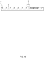
- the tray 1 As illustrated in FIGS. 1a and 1b , which illustrate the tray for transport and storage according to the related art, the tray 1 according to the related art has a rectangular plate shape and has a structure in which a plurality of grooves 2 are defined along horizontal and vertical rows so that a battery cap 3 is laid horizontally and seated on a top surface of the tray 1.
- the structure of the tray 1 according to the related art has been difficult to supply a sufficient quantity of battery caps 3 at once as a production rate in a production line increases. That is, when a predetermined quantity of battery caps 3 has to be provided in the production line, the number of battery caps 3 mounted on each tray decreases, and thus, more trays 1 are required. As a result, a large space and much time are required for transporting and storing the trays 1.
- a main object of the present invention is to provide a tray for loading a battery cap, which is capable of mounting more battery caps per unit volume when compared to the structure according to the related art.
- a tray for loading a battery cap, on which the battery cap is mounted comprises: first trays, each having a top surface, in which first grooves are defined, and a bottom surface, in which second grooves are defined; and second trays, each having a top surface, in which third grooves are defined, and a bottom surface, in which fourth grooves are defined and disposed above or below the first tray, wherein, when the first tray is disposed above the second tray, each of the second grooves and each of the third grooves communicate with each other to provide a communication space, and when the first tray is disposed below the second tray, each of the first grooves and each of the fourth grooves communicate with each other to provide a communication space, wherein the battery cap is mounted in a vertically erect state in the first tray and the second tray.
- the battery cap may mean a disk-shaped battery cap coupled to an upper end of a can of the cylindrical secondary battery.
- the battery cap may be replaced with a button-type secondary battery or different disk-shaped components of the secondary battery, such as a top cap placed at the uppermost end of the battery cap.
- the battery cap may be a plate-shaped component that is mounted vertically with an area greater than a thickness thereof.
- the first grooves and the second grooves may be alternately arranged so that the second groove is disposed between the first grooves adjacent to each other in the first tray, and the third grooves and the fourth grooves may be alternately arranged so that the fourth groove is disposed between the third grooves adjacent to each other in the second tray.
- an upper end of the battery cap may be restricted in the second groove or the fourth groove, and a lower end of the battery cap may be restricted in the first groove or the third groove to prevent the first tray and the second tray from being separated.
- the first tray may have a rectangular plate shape in which the first grooves and the second grooves are alternately arranged along a vertical line, wherein the first trays having the same shape may be continuously arranged along a horizontal line, and the second tray may have a rectangular plate shape in which the third grooves and the fourth grooves are arranged along the vertical line, wherein the second trays having the same shape may be continuously arranged along the horizontal line.
- the first tray may have a zigzag-shaped cross-section vertically along the vertical line in a region in which the first grooves and the second grooves are alternately arranged
- the second tray may have a zigzag-shaped cross-section vertically along the vertical line in a region in which the third grooves and the fourth grooves are alternately arranged.
- the first tray and the second tray may have the same area, and the first trays and the second trays may be alternately and continuously stacked.
- each of the first groove and the second groove may have a width in which the battery cap is maintained in the erect state.
- the number of first grooves arranged in the vertical line and the number of first grooves arranged in the horizontal line may be the same, and in the second tray, the number of third grooves arranged in the vertical line and the number of third grooves arranged in the horizontal line may be the same.
- the uppermost end of the battery cap may not contact the first tray or the second tray.
- each of the first tray and the second tray may be made of a material having hardness less than that of the battery cap.
- the first tray may have one of a protrusion or a groove at a portion having a shape protruding upward by the second groove between the first grooves adjacent to each other, and the other of the protrusion or the groove at a portion having a shape protruding downward by the first groove between the second grooves adjacent to each other
- the second tray may have one of a protrusion or a groove, which is engaged with the protrusion or the groove disposed at a lower portion of the first tray, at a portion having a shape protruding upward by the fourth groove between the third grooves, and the other of the protrusion or the groove at a portion having a shape protruding downward by the third groove between the fourth grooves adjacent to each other.
- a magnet may be attached to a portion at which the first tray and the second tray contact each other to guide the first tray and the second tray to be disposed in position by magnetism when the first tray and the second tray are stacked.
- the battery cap stacked below may be disposed between the battery caps stacked above to reduce the stacked height. That is, in the present invention, one of the first trays and one of the second trays may be stacked in the two layers, and the height of the battery caps mounted on the stacked trays may be lower than twice the diameter of the battery cap. Therefore, the number of stacked trays may further increase.
- the upper end of the battery cap may be restricted in the second groove or the fourth groove, and the lower end of the battery cap may be restricted in the first groove or the third groove to prevent the first tray and the second tray from being separated. That is, it is possible to more robustly prevent the trays from falling down by the impact applied from the lateral direction.
- each of the first groove and the third groove of the first tray and the second tray has the width in which the battery cap is maintained in the erect state when the battery cap is seated in the erect state, the dispensing equipment may more easily dispense one or multiple battery caps when compared to the state in which the dispensing equipment is laid in the production process.
- each of the first tray and the second tray is made of the material having hardness less than that of the battery case, when the trays and the battery cap collide with each other, it may prevent the battery cap from being scratched or damaged.
- the seated positions of the first tray and the second tray may be guided by the protrusion and the groove or by the magnet and thus be prevented from being shaken after being seated.
- the present invention relates to a tray for loading a battery cap, on which a disk-shaped battery cap 30 is mounted, i.e., a tray for loading a battery cap 30, in which the battery cap 30 is mounted in a vertically erect state so that more battery caps 30 per unit volume are capable of being mounted when compared to the structure of the battery cap according to the related art, and thus, the battery caps 30 are more easily stored, transported, and dispensed.
- FIGS. 2 to 5 illustrate a configuration of a first tray and a second tray according to a first embodiment of the present invention.
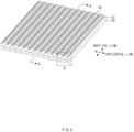
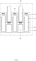
- FIG. 2 is a perspective view illustrating a state in which the first tray is stacked on the second tray in a state in which a battery cap is mounted on the first tray and the second tray according to a first embodiment of the present invention
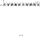
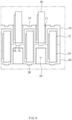
- FIG. 3 is a cross-sectional view taken along line A-A in FIG. 2
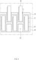
- FIG. 4 is an enlarged view of a portion C in FIG. 3
- FIG. 5 is a see-through view illustrating a portion B in FIG. 2 .
- the tray according to the first embodiment of the present invention comprises a first tray 10 and a second tray 20.
- the first tray 10 and the second tray 20 are alternately and continuously stacked.
- the first tray 10 has a structure in which a first groove 11 is defined in a top surface thereof, and a second groove 12 is defined in a bottom surface thereof, and the second tray 20 has a structure in which a third groove 23 is defined in a top surface thereof, and a fourth groove 24 is defined in a bottom surface thereof.
- the second tray 20 may be stacked above and below the first tray 10.
- the first tray 10 When the first tray 10 is disposed above the second tray 20, the second groove 12 and the third groove 23 communicate with each other to provide a communication space, and when the first tray 10 is disposed below the second tray 20, the first groove 11 and the fourth groove 24 communicate with each other to provide a communication space.
- the battery cap 30 is mounted in a vertically erect state in the first tray 10 and the second tray 20. That is, the battery cap 30 is mounted in the vertically erect state within the first groove 11 and the third groove 23, i.e., in the communication space between the second groove 12 and the third groove 23 and the communication space between the first groove 11 and the fourth groove 24.
- the battery cap 30 means a disk-shaped battery cap coupled to an upper end of a can of a cylindrical secondary battery.
- the battery cap 30 may be replaced with a button-type secondary battery or different disk-shaped components of the secondary battery, such as a top cap placed at the uppermost end of the battery cap 30.
- the first tray having the same shape are continuously arranged along a horizontal line, ad as illustrated in FIGS. 3 and 4 , the first tray 10 has a rectangular plate shape in which the first grooves 11 and the second grooves 12 are alternately arranged along a vertical line.
- the second tray 20 has a rectangular plate shape in which the third grooves 23 and the fourth grooves 24 are arranged along the vertical line, and the second trays 20 having the same shape are continuously arranged along the horizontal line.
- the second tray 20 is different from the first tray 10 in the positions of the grooves 11 and 12 so that the third groove 23 and the fourth groove 24 of the second tray 20 respectively communicate with the second groove 12 and the first groove 11.
- first tray 10 and the second tray 20 have the rectangular plate shapes having the same area, respectively, the first trays 10 and the second trays 20 may be alternately and continuously stacked.
- the number of first grooves 11 provided in the vertical line and the number of first grooves 11 provided in the horizontal line may be the same, and in the second tray 20, the number of third grooves 23 provided in the vertical line and the number of third grooves 23 provided in the horizontal line may be the same (however, the arrangement and number of grooves may be different according to a shape and size of the tray).
- first grooves 11 and the second grooves 12 may be alternately arranged so that the second groove 12 is disposed between the first grooves 11 adjacent to each other in the first tray 10
- the third grooves 23 and the fourth grooves 24 may be alternately arranged so that the fourth groove 24 is disposed between the third grooves 23 adjacent to each other in the second tray 20.
- the second groove 12 and the third groove 23 may communicate with each other
- the first groove 11 and the fourth groove 24 may communicate with each other according to the stacked positions of the first tray 10 and the second tray 20.
- the first tray 10 has a zigzag-shaped cross-section vertically along the vertical line in the region in which the first grooves 11 and the second grooves 12 are alternately arranged
- the second tray 20 has a zigzag-shaped cross-section vertically along the vertical line in the region in which the third grooves 23 and the fourth grooves 24 are alternately arranged
- the battery cap 30 may be mounted in the space between the grooves, and thus, the space may have a size greater than that of the battery cap 30.
- each of the first groove 11 and the third groove 23 has a width in which the battery cap 30 is maintained in the erect state when the battery cap 30 is seated in the erect state.
- the uppermost end of the battery cap 30 does not contact the first tray 10 or the second tray 20.
- each of the first tray 10 and the second tray 20 are made of a material having hardness less than that of the battery cap 30.
- the each of the first tray 10 and the second tray 20 is made of a relatively soft material when compared to the battery cap 30 so as to suppress or minimize an occurrence of scratch or deformation of the battery cap 30.
- the battery cap 30 since the battery cap 30 is mounted in the vertically erect state in the first tray 10 and the second tray 20, more battery caps 30 per unit area may be loaded when compared to the tray mounted to be laid horizontally according to the related art.
- the battery caps 30 stacked below may be placed between the battery caps 30 stacked above to reduce a stacked height. That is, as illustrated in FIG. 5 , when the first tray 10 is stacked above the second tray 20, the total height may be less than twice a diameter of the battery cap 30. Therefore, the number of stacked trays may further increase.
- each of the first tray 10 and the second tray 20 is made of the material having the hardness less than that of the battery cap 30, the occurrence of the stretch or damage of the battery cap 30 may be prevented when the trays 10 and 20 collide with the battery cap 30.
- a structure which is capable of fixing a first tray 10 and a second tray 20 to prevent the first tray 10 and the second tray 20 from being shaken in a state in which a battery cap 30 is mounted between the first tray 10 and the second tray 20, is provided.
- the first tray 10 has a groove 14 in a portion having a shape protruding upward by a second groove 12 between first grooves 11 adjacent to each other. Also, a protrusion 15 is disposed to protrude downward at a portion having a shape protruding downward by the first groove 11 between the second grooves 12 adjacent to each other.
- the second tray 20 has a groove 25, which is engaged with the protrusion 15 disposed at a lower portion of the first tray 10, in a portion having a shape protruding upward by a fourth groove 24 between third grooves 23, and a protrusion 26 is disposed at a portion having a shape protruding downward by the third groove 23 between the fourth grooves 24 adjacent to each other.
- the protrusions 15 and 26 may be fitted into the grooves 14 and 25 and thus be prevented from being separated from the grooves 14 and 25 by a weight of each of the tray and the battery cap 30, which are disposed above the first and second trays 10 and 20, thereby stably stacking the trays in more stages.
- a structure that is capable of preventing a first tray 10 and a second tray 20 from being shaken and capable of guiding the first tray 10 and the second tray 20 to be disposed in position when seated.
- a magnet 50 may be attached to one of portions contacting each other when the first tray 10 and the second tray 20 are seated in position, and a metal may be placed on the other portion to be in contact with the magnet 50 so as to be magnetized to generate attraction force or may be coated with a predetermined thickness.
- magnets 50 may be respectively disposed at each of portions at which the first tray 10 and the second tray contact each other to generate the attraction force at the positions contacting each other so that the portions having opposite polarities face each other, thereby guiding the first tray 10 and the second tray 20 to be disposed in position.
- the positions of the first and second trays 10 and 20, which are to be seated may be guided by magnetism.
- the first and second trays 10 and 20 may be prevented from being shaken.
Landscapes
- Engineering & Computer Science (AREA)
- Mechanical Engineering (AREA)
- Chemical & Material Sciences (AREA)
- Chemical Kinetics & Catalysis (AREA)
- Electrochemistry (AREA)
- General Chemical & Material Sciences (AREA)
- Manufacturing & Machinery (AREA)
- Ceramic Engineering (AREA)
- Stackable Containers (AREA)
- Battery Mounting, Suspending (AREA)
Applications Claiming Priority (2)
| Application Number | Priority Date | Filing Date | Title |
|---|---|---|---|
| KR1020190082166A KR102841897B1 (ko) | 2019-07-08 | 2019-07-08 | 전지캡 적재용 트레이 |
| PCT/KR2020/008765 WO2021006572A1 (ko) | 2019-07-08 | 2020-07-03 | 전지캡 적재용 트레이 |
Publications (3)
| Publication Number | Publication Date |
|---|---|
| EP3972004A1 true EP3972004A1 (de) | 2022-03-23 |
| EP3972004A4 EP3972004A4 (de) | 2022-07-06 |
| EP3972004B1 EP3972004B1 (de) | 2025-06-04 |
Family
ID=74114290
Family Applications (1)
| Application Number | Title | Priority Date | Filing Date |
|---|---|---|---|
| EP20837143.5A Active EP3972004B1 (de) | 2019-07-08 | 2020-07-03 | Ladeschale für batteriekappen |
Country Status (7)
| Country | Link |
|---|---|
| US (1) | US20220355968A1 (de) |
| EP (1) | EP3972004B1 (de) |
| KR (1) | KR102841897B1 (de) |
| CN (1) | CN114007946A (de) |
| ES (1) | ES3034139T3 (de) |
| HU (1) | HUE071953T2 (de) |
| WO (1) | WO2021006572A1 (de) |
Families Citing this family (3)
| Publication number | Priority date | Publication date | Assignee | Title |
|---|---|---|---|---|
| CN115892675B (zh) * | 2022-11-23 | 2024-06-28 | 厦门海辰储能科技股份有限公司 | 搬运装置 |
| US12275578B1 (en) | 2023-12-21 | 2025-04-15 | Solon Manufacturing Company | Product packaging for washers and method of use |
| US20250236433A1 (en) * | 2024-01-23 | 2025-07-24 | Redwood Materials, Inc. | Battery storage and transport system |
Family Cites Families (16)
| Publication number | Priority date | Publication date | Assignee | Title |
|---|---|---|---|---|
| US2936922A (en) * | 1958-03-07 | 1960-05-17 | Keyes Fibre Co | Molded pulp packing tray |
| US3141596A (en) * | 1963-01-03 | 1964-07-21 | Waldorf Paper Prod Co | Dispensing containers |
| US3306462A (en) * | 1965-03-31 | 1967-02-28 | Cruz Edward Da | Storage case for disk-shaped objects |
| FR2768066B1 (fr) * | 1997-09-08 | 1999-11-26 | Gilson Sa | Portoir pour cones de pipette multicanaux |
| JP2003104476A (ja) * | 2001-10-01 | 2003-04-09 | Mikiro Akigawa | 卵収容トレー |
| US6662949B2 (en) * | 2001-12-28 | 2003-12-16 | Hon Hai Precision Ind. Co., Ltd. | Package for mechanical or electrical components |
| KR20070051296A (ko) * | 2007-02-28 | 2007-05-17 | 스펜션 엘엘씨 | 적층형 반도체 장치용 캐리어 구성, 그 제조 방법 및적층형 반도체 장치의 제조 방법 |
| CN201043034Y (zh) * | 2007-04-27 | 2008-04-02 | 中山大洋电机股份有限公司 | 一种小功率电机的循环回收包装 |
| CN101952992A (zh) * | 2008-02-12 | 2011-01-19 | 松下电器产业株式会社 | 电池收纳托盘及使用其的集合电池收纳托盘 |
| CN203127507U (zh) * | 2013-01-31 | 2013-08-14 | 中山大洋电机制造有限公司 | 一种电机吸塑包装结构 |
| KR102210880B1 (ko) * | 2014-03-31 | 2021-02-02 | 삼성에스디아이 주식회사 | 배터리 트레이 및 이를 구비하는 배터리 적재용기 |
| CH713290B1 (de) * | 2016-12-23 | 2020-08-31 | Varta Microbattery Gmbh | Mehrteilige Transport- und Lagerverpackung für vorassemblierte elektrochemische Zellen. |
| JP6890809B2 (ja) * | 2017-07-20 | 2021-06-18 | 三甲株式会社 | トレー |
| CN207239610U (zh) * | 2017-09-19 | 2018-04-17 | 科源(天津)电源部品有限公司 | 一种锂电池盖帽上料盘 |
| CN108011062A (zh) * | 2017-12-13 | 2018-05-08 | 北方奥钛纳米技术有限公司 | 纽扣电池放置托盘 |
| CN208344912U (zh) * | 2018-06-14 | 2019-01-08 | 湖北三江航天万峰科技发展有限公司 | 一种电子元器件专用托盘 |
-
2019
- 2019-07-08 KR KR1020190082166A patent/KR102841897B1/ko active Active
-
2020
- 2020-07-03 ES ES20837143T patent/ES3034139T3/es active Active
- 2020-07-03 WO PCT/KR2020/008765 patent/WO2021006572A1/ko not_active Ceased
- 2020-07-03 HU HUE20837143A patent/HUE071953T2/hu unknown
- 2020-07-03 CN CN202080042320.7A patent/CN114007946A/zh active Pending
- 2020-07-03 US US17/618,723 patent/US20220355968A1/en not_active Abandoned
- 2020-07-03 EP EP20837143.5A patent/EP3972004B1/de active Active
Also Published As
| Publication number | Publication date |
|---|---|
| KR20210006181A (ko) | 2021-01-18 |
| ES3034139T3 (en) | 2025-08-13 |
| HUE071953T2 (hu) | 2025-10-28 |
| EP3972004A4 (de) | 2022-07-06 |
| CN114007946A (zh) | 2022-02-01 |
| US20220355968A1 (en) | 2022-11-10 |
| KR102841897B1 (ko) | 2025-08-04 |
| WO2021006572A1 (ko) | 2021-01-14 |
| EP3972004B1 (de) | 2025-06-04 |
Similar Documents
| Publication | Publication Date | Title |
|---|---|---|
| EP3972004B1 (de) | Ladeschale für batteriekappen | |
| US6396242B2 (en) | Battery charging and discharging system | |
| US10243193B2 (en) | Battery pack | |
| KR102587699B1 (ko) | 배터리 팩 | |
| US20150303412A1 (en) | Embedded frame for pouch-type secondary battery and secondary battery having embedded frame | |
| US20090061294A1 (en) | Battery case and battery pack using the same | |
| US20160149277A1 (en) | Frame for secondary battery and battery module including the same | |
| KR101208998B1 (ko) | 전극판 이송장치 | |
| KR101402539B1 (ko) | 소성용기 | |
| US20120231302A1 (en) | Case for battery pack and battery pack having the same | |
| US20110117414A1 (en) | Secondary Battery | |
| JP2014212113A (ja) | 二次電池用バッテリーセルおよびこれを含むバッテリーパック | |
| US20250105440A1 (en) | Battery module, and battery pack and vehicle comprising the same | |
| US12362434B2 (en) | Button-type secondary battery | |
| KR20180007854A (ko) | 전지셀 활성화 트레이 | |
| US11929500B2 (en) | Electrode assembly | |
| US10262809B2 (en) | Electric energy storage device having improved terminal structure | |
| US20230099231A1 (en) | Power storage device | |
| EP3783730B1 (de) | Sekundärbatterie | |
| KR200225219Y1 (ko) | 충전기 | |
| US11223085B2 (en) | Battery pack fixing apparatus | |
| US12567636B2 (en) | Battery pack having handle | |
| US20240282999A1 (en) | Battery tray and method for manufacturing battery using same | |
| KR101864918B1 (ko) | 배터리 모듈 및 배터리 모듈 제조방법 | |
| US20100330412A1 (en) | Secondary battery |
Legal Events
| Date | Code | Title | Description |
|---|---|---|---|
| STAA | Information on the status of an ep patent application or granted ep patent |
Free format text: STATUS: THE INTERNATIONAL PUBLICATION HAS BEEN MADE |
|
| PUAI | Public reference made under article 153(3) epc to a published international application that has entered the european phase |
Free format text: ORIGINAL CODE: 0009012 |
|
| STAA | Information on the status of an ep patent application or granted ep patent |
Free format text: STATUS: REQUEST FOR EXAMINATION WAS MADE |
|
| 17P | Request for examination filed |
Effective date: 20211213 |
|
| AK | Designated contracting states |
Kind code of ref document: A1 Designated state(s): AL AT BE BG CH CY CZ DE DK EE ES FI FR GB GR HR HU IE IS IT LI LT LU LV MC MK MT NL NO PL PT RO RS SE SI SK SM TR |
|
| RAP3 | Party data changed (applicant data changed or rights of an application transferred) |
Owner name: LG ENERGY SOLUTION, LTD. |
|
| REG | Reference to a national code |
Ref country code: DE Free format text: PREVIOUS MAIN CLASS: H99Z9999999999 Ref country code: DE Ref legal event code: R079 Ref document number: 602020052402 Country of ref document: DE Free format text: PREVIOUS MAIN CLASS: H99Z9999999999 Ipc: H01M0050152000 |
|
| A4 | Supplementary search report drawn up and despatched |
Effective date: 20220608 |
|
| RIC1 | Information provided on ipc code assigned before grant |
Ipc: H01M 10/04 20060101ALI20220601BHEP Ipc: H01M 50/152 20210101AFI20220601BHEP |
|
| DAV | Request for validation of the european patent (deleted) | ||
| DAX | Request for extension of the european patent (deleted) | ||
| GRAP | Despatch of communication of intention to grant a patent |
Free format text: ORIGINAL CODE: EPIDOSNIGR1 |
|
| STAA | Information on the status of an ep patent application or granted ep patent |
Free format text: STATUS: GRANT OF PATENT IS INTENDED |
|
| INTG | Intention to grant announced |
Effective date: 20250321 |
|
| GRAS | Grant fee paid |
Free format text: ORIGINAL CODE: EPIDOSNIGR3 |
|
| GRAA | (expected) grant |
Free format text: ORIGINAL CODE: 0009210 |
|
| STAA | Information on the status of an ep patent application or granted ep patent |
Free format text: STATUS: THE PATENT HAS BEEN GRANTED |
|
| P01 | Opt-out of the competence of the unified patent court (upc) registered |
Free format text: CASE NUMBER: APP_16834/2025 Effective date: 20250407 |
|
| AK | Designated contracting states |
Kind code of ref document: B1 Designated state(s): AL AT BE BG CH CY CZ DE DK EE ES FI FR GB GR HR HU IE IS IT LI LT LU LV MC MK MT NL NO PL PT RO RS SE SI SK SM TR |
|
| REG | Reference to a national code |
Ref country code: GB Ref legal event code: FG4D |
|
| REG | Reference to a national code |
Ref country code: CH Ref legal event code: EP |
|
| REG | Reference to a national code |
Ref country code: DE Ref legal event code: R096 Ref document number: 602020052402 Country of ref document: DE |
|
| REG | Reference to a national code |
Ref country code: IE Ref legal event code: FG4D |
|
| PGFP | Annual fee paid to national office [announced via postgrant information from national office to epo] |
Ref country code: GB Payment date: 20250624 Year of fee payment: 6 |
|
| PGFP | Annual fee paid to national office [announced via postgrant information from national office to epo] |
Ref country code: BE Payment date: 20250623 Year of fee payment: 6 |
|
| PGFP | Annual fee paid to national office [announced via postgrant information from national office to epo] |
Ref country code: FR Payment date: 20250624 Year of fee payment: 6 |
|
| REG | Reference to a national code |
Ref country code: ES Ref legal event code: FG2A Ref document number: 3034139 Country of ref document: ES Kind code of ref document: T3 Effective date: 20250813 |
|
| REG | Reference to a national code |
Ref country code: NL Ref legal event code: MP Effective date: 20250604 |
|
| PG25 | Lapsed in a contracting state [announced via postgrant information from national office to epo] |
Ref country code: FI Free format text: LAPSE BECAUSE OF FAILURE TO SUBMIT A TRANSLATION OF THE DESCRIPTION OR TO PAY THE FEE WITHIN THE PRESCRIBED TIME-LIMIT Effective date: 20250604 |
|
| PGFP | Annual fee paid to national office [announced via postgrant information from national office to epo] |
Ref country code: ES Payment date: 20250822 Year of fee payment: 6 |
|
| PGFP | Annual fee paid to national office [announced via postgrant information from national office to epo] |
Ref country code: DE Payment date: 20250624 Year of fee payment: 6 |
|
| REG | Reference to a national code |
Ref country code: LT Ref legal event code: MG9D |
|
| PG25 | Lapsed in a contracting state [announced via postgrant information from national office to epo] |
Ref country code: NO Free format text: LAPSE BECAUSE OF FAILURE TO SUBMIT A TRANSLATION OF THE DESCRIPTION OR TO PAY THE FEE WITHIN THE PRESCRIBED TIME-LIMIT Effective date: 20250904 Ref country code: GR Free format text: LAPSE BECAUSE OF FAILURE TO SUBMIT A TRANSLATION OF THE DESCRIPTION OR TO PAY THE FEE WITHIN THE PRESCRIBED TIME-LIMIT Effective date: 20250905 |
|
| PG25 | Lapsed in a contracting state [announced via postgrant information from national office to epo] |
Ref country code: PL Free format text: LAPSE BECAUSE OF FAILURE TO SUBMIT A TRANSLATION OF THE DESCRIPTION OR TO PAY THE FEE WITHIN THE PRESCRIBED TIME-LIMIT Effective date: 20250604 |
|
| PG25 | Lapsed in a contracting state [announced via postgrant information from national office to epo] |
Ref country code: BG Free format text: LAPSE BECAUSE OF FAILURE TO SUBMIT A TRANSLATION OF THE DESCRIPTION OR TO PAY THE FEE WITHIN THE PRESCRIBED TIME-LIMIT Effective date: 20250604 |
|
| PGFP | Annual fee paid to national office [announced via postgrant information from national office to epo] |
Ref country code: HU Payment date: 20250929 Year of fee payment: 6 |
|
| PG25 | Lapsed in a contracting state [announced via postgrant information from national office to epo] |
Ref country code: HR Free format text: LAPSE BECAUSE OF FAILURE TO SUBMIT A TRANSLATION OF THE DESCRIPTION OR TO PAY THE FEE WITHIN THE PRESCRIBED TIME-LIMIT Effective date: 20250604 |
|
| PG25 | Lapsed in a contracting state [announced via postgrant information from national office to epo] |
Ref country code: RS Free format text: LAPSE BECAUSE OF FAILURE TO SUBMIT A TRANSLATION OF THE DESCRIPTION OR TO PAY THE FEE WITHIN THE PRESCRIBED TIME-LIMIT Effective date: 20250904 |
|
| REG | Reference to a national code |
Ref country code: HU Ref legal event code: AG4A Ref document number: E071953 Country of ref document: HU |
|
| PG25 | Lapsed in a contracting state [announced via postgrant information from national office to epo] |
Ref country code: LV Free format text: LAPSE BECAUSE OF FAILURE TO SUBMIT A TRANSLATION OF THE DESCRIPTION OR TO PAY THE FEE WITHIN THE PRESCRIBED TIME-LIMIT Effective date: 20250604 |
|
| PG25 | Lapsed in a contracting state [announced via postgrant information from national office to epo] |
Ref country code: NL Free format text: LAPSE BECAUSE OF FAILURE TO SUBMIT A TRANSLATION OF THE DESCRIPTION OR TO PAY THE FEE WITHIN THE PRESCRIBED TIME-LIMIT Effective date: 20250604 |
|
| PG25 | Lapsed in a contracting state [announced via postgrant information from national office to epo] |
Ref country code: PT Free format text: LAPSE BECAUSE OF FAILURE TO SUBMIT A TRANSLATION OF THE DESCRIPTION OR TO PAY THE FEE WITHIN THE PRESCRIBED TIME-LIMIT Effective date: 20251006 |
|
| REG | Reference to a national code |
Ref country code: AT Ref legal event code: MK05 Ref document number: 1801287 Country of ref document: AT Kind code of ref document: T Effective date: 20250604 |
|
| PG25 | Lapsed in a contracting state [announced via postgrant information from national office to epo] |
Ref country code: IS Free format text: LAPSE BECAUSE OF FAILURE TO SUBMIT A TRANSLATION OF THE DESCRIPTION OR TO PAY THE FEE WITHIN THE PRESCRIBED TIME-LIMIT Effective date: 20251004 |
|
| PG25 | Lapsed in a contracting state [announced via postgrant information from national office to epo] |
Ref country code: AT Free format text: LAPSE BECAUSE OF FAILURE TO SUBMIT A TRANSLATION OF THE DESCRIPTION OR TO PAY THE FEE WITHIN THE PRESCRIBED TIME-LIMIT Effective date: 20250604 Ref country code: SM Free format text: LAPSE BECAUSE OF FAILURE TO SUBMIT A TRANSLATION OF THE DESCRIPTION OR TO PAY THE FEE WITHIN THE PRESCRIBED TIME-LIMIT Effective date: 20250604 |
|
| PG25 | Lapsed in a contracting state [announced via postgrant information from national office to epo] |
Ref country code: CZ Free format text: LAPSE BECAUSE OF FAILURE TO SUBMIT A TRANSLATION OF THE DESCRIPTION OR TO PAY THE FEE WITHIN THE PRESCRIBED TIME-LIMIT Effective date: 20250604 |
|
| PG25 | Lapsed in a contracting state [announced via postgrant information from national office to epo] |
Ref country code: EE Free format text: LAPSE BECAUSE OF FAILURE TO SUBMIT A TRANSLATION OF THE DESCRIPTION OR TO PAY THE FEE WITHIN THE PRESCRIBED TIME-LIMIT Effective date: 20250604 |
|
| PG25 | Lapsed in a contracting state [announced via postgrant information from national office to epo] |
Ref country code: SK Free format text: LAPSE BECAUSE OF FAILURE TO SUBMIT A TRANSLATION OF THE DESCRIPTION OR TO PAY THE FEE WITHIN THE PRESCRIBED TIME-LIMIT Effective date: 20250604 Ref country code: RO Free format text: LAPSE BECAUSE OF FAILURE TO SUBMIT A TRANSLATION OF THE DESCRIPTION OR TO PAY THE FEE WITHIN THE PRESCRIBED TIME-LIMIT Effective date: 20250604 |
|
| PG25 | Lapsed in a contracting state [announced via postgrant information from national office to epo] |
Ref country code: IT Free format text: LAPSE BECAUSE OF FAILURE TO SUBMIT A TRANSLATION OF THE DESCRIPTION OR TO PAY THE FEE WITHIN THE PRESCRIBED TIME-LIMIT Effective date: 20250604 |
|
| REG | Reference to a national code |
Ref country code: CH Ref legal event code: H13 Free format text: ST27 STATUS EVENT CODE: U-0-0-H10-H13 (AS PROVIDED BY THE NATIONAL OFFICE) Effective date: 20260224 |
|
| REG | Reference to a national code |
Ref country code: DE Ref legal event code: R097 Ref document number: 602020052402 Country of ref document: DE |
|
| PG25 | Lapsed in a contracting state [announced via postgrant information from national office to epo] |
Ref country code: LU Free format text: LAPSE BECAUSE OF NON-PAYMENT OF DUE FEES Effective date: 20250703 |
|
| PG25 | Lapsed in a contracting state [announced via postgrant information from national office to epo] |
Ref country code: MC Free format text: LAPSE BECAUSE OF FAILURE TO SUBMIT A TRANSLATION OF THE DESCRIPTION OR TO PAY THE FEE WITHIN THE PRESCRIBED TIME-LIMIT Effective date: 20250604 |
|
| PLBE | No opposition filed within time limit |
Free format text: ORIGINAL CODE: 0009261 |
|
| STAA | Information on the status of an ep patent application or granted ep patent |
Free format text: STATUS: NO OPPOSITION FILED WITHIN TIME LIMIT |
|
| PG25 | Lapsed in a contracting state [announced via postgrant information from national office to epo] |
Ref country code: DK Free format text: LAPSE BECAUSE OF FAILURE TO SUBMIT A TRANSLATION OF THE DESCRIPTION OR TO PAY THE FEE WITHIN THE PRESCRIBED TIME-LIMIT Effective date: 20250604 |
|
| REG | Reference to a national code |
Ref country code: CH Ref legal event code: L10 Free format text: ST27 STATUS EVENT CODE: U-0-0-L10-L00 (AS PROVIDED BY THE NATIONAL OFFICE) Effective date: 20260416 |
|
| PG25 | Lapsed in a contracting state [announced via postgrant information from national office to epo] |
Ref country code: CH Free format text: LAPSE BECAUSE OF NON-PAYMENT OF DUE FEES Effective date: 20250731 |