EP3971679B1 - Modularer rahmen - Google Patents
Modularer rahmen Download PDFInfo
- Publication number
- EP3971679B1 EP3971679B1 EP21189250.0A EP21189250A EP3971679B1 EP 3971679 B1 EP3971679 B1 EP 3971679B1 EP 21189250 A EP21189250 A EP 21189250A EP 3971679 B1 EP3971679 B1 EP 3971679B1
- Authority
- EP
- European Patent Office
- Prior art keywords
- key hole
- processing region
- modular frame
- key
- configuration
- Prior art date
- Legal status (The legal status is an assumption and is not a legal conclusion. Google has not performed a legal analysis and makes no representation as to the accuracy of the status listed.)
- Active
Links
Images


Classifications
-
- H—ELECTRICITY
- H01—ELECTRIC ELEMENTS
- H01H—ELECTRIC SWITCHES; RELAYS; SELECTORS; EMERGENCY PROTECTIVE DEVICES
- H01H13/00—Switches having rectilinearly-movable operating part or parts adapted for pushing or pulling in one direction only, e.g. push-button switch
- H01H13/70—Switches having rectilinearly-movable operating part or parts adapted for pushing or pulling in one direction only, e.g. push-button switch having a plurality of operating members associated with different sets of contacts, e.g. keyboard
- H01H13/86—Switches having rectilinearly-movable operating part or parts adapted for pushing or pulling in one direction only, e.g. push-button switch having a plurality of operating members associated with different sets of contacts, e.g. keyboard characterised by the casing, e.g. sealed casings or casings reducible in size
-
- G—PHYSICS
- G06—COMPUTING OR CALCULATING; COUNTING
- G06F—ELECTRIC DIGITAL DATA PROCESSING
- G06F1/00—Details not covered by groups G06F3/00 - G06F13/00 and G06F21/00
- G06F1/16—Constructional details or arrangements
- G06F1/1613—Constructional details or arrangements for portable computers
- G06F1/1633—Constructional details or arrangements of portable computers not specific to the type of enclosures covered by groups G06F1/1615 - G06F1/1626
- G06F1/1656—Details related to functional adaptations of the enclosure, e.g. to provide protection against EMI, shock, water, or to host detachable peripherals like a mouse or removable expansions units like PCMCIA cards, or to provide access to internal components for maintenance or to removable storage supports like CDs or DVDs, or to mechanically mount accessories
-
- G—PHYSICS
- G06—COMPUTING OR CALCULATING; COUNTING
- G06F—ELECTRIC DIGITAL DATA PROCESSING
- G06F3/00—Input arrangements for transferring data to be processed into a form capable of being handled by the computer; Output arrangements for transferring data from processing unit to output unit, e.g. interface arrangements
- G06F3/01—Input arrangements or combined input and output arrangements for interaction between user and computer
- G06F3/02—Input arrangements using manually operated switches, e.g. using keyboards or dials
- G06F3/0202—Constructional details or processes of manufacture of the input device
-
- H—ELECTRICITY
- H01—ELECTRIC ELEMENTS
- H01H—ELECTRIC SWITCHES; RELAYS; SELECTORS; EMERGENCY PROTECTIVE DEVICES
- H01H13/00—Switches having rectilinearly-movable operating part or parts adapted for pushing or pulling in one direction only, e.g. push-button switch
- H01H13/70—Switches having rectilinearly-movable operating part or parts adapted for pushing or pulling in one direction only, e.g. push-button switch having a plurality of operating members associated with different sets of contacts, e.g. keyboard
- H01H13/88—Processes specially adapted for manufacture of rectilinearly movable switches having a plurality of operating members associated with different sets of contacts, e.g. keyboards
-
- G—PHYSICS
- G06—COMPUTING OR CALCULATING; COUNTING
- G06F—ELECTRIC DIGITAL DATA PROCESSING
- G06F1/00—Details not covered by groups G06F3/00 - G06F13/00 and G06F21/00
- G06F1/16—Constructional details or arrangements
- G06F1/1613—Constructional details or arrangements for portable computers
- G06F1/1633—Constructional details or arrangements of portable computers not specific to the type of enclosures covered by groups G06F1/1615 - G06F1/1626
- G06F1/1662—Details related to the integrated keyboard
-
- H—ELECTRICITY
- H01—ELECTRIC ELEMENTS
- H01H—ELECTRIC SWITCHES; RELAYS; SELECTORS; EMERGENCY PROTECTIVE DEVICES
- H01H2223/00—Casings
- H01H2223/034—Bezel
-
- H—ELECTRICITY
- H01—ELECTRIC ELEMENTS
- H01H—ELECTRIC SWITCHES; RELAYS; SELECTORS; EMERGENCY PROTECTIVE DEVICES
- H01H2231/00—Applications
- H01H2231/002—Calculator, computer
-
- H—ELECTRICITY
- H01—ELECTRIC ELEMENTS
- H01H—ELECTRIC SWITCHES; RELAYS; SELECTORS; EMERGENCY PROTECTIVE DEVICES
- H01H2233/00—Key modules
- H01H2233/03—Key modules mounted on support plate or frame
- H01H2233/032—Locating pins
Definitions
- the disclosure relates to a modular frame; particularly, the disclosure relates to a modular frame that may be selectively switched to different keyboard configurations.
- keyboards are mainly divided into three keyboard configurations, i.e., US keyboard, UK keyboard, and JIS keyboard. Therefore, in production, it is necessary to develop corresponding molds in accordance with the US, UK, and JIS configurations. In the current way, the production costs of the keyboard are increased.
- CN 201 622 533 U discloses a modularized frame of a keyboard, including a keyboard container, which comprises a letter function hole unit, a number function hole unit, a Space function hole, an Enter function hole, a right Shift function hole, a left Shift function hole and a Backspace function hole.
- the Space function hole, the right Shift function hole and the left Shift function hole can hold at least one key cap.
- the Enter function hole can hold two key caps, one of which is Enter key cap.
- the present invention is provided by the appended claims.
- the following disclosure serves a better understanding of the present invention. Accordingly, the disclosure provides a modular frame, which is applicable to US, UK, and JIS keyboard configurations by arranging forms of push-button holes through processing. As such, it is possible to prevent frames of different configurations from material shortage or excess inventory, effectively saving the production costs.
- a modular frame of the disclosure includes a push-button area.
- the push-button area includes a function key hole group, an alphabet key hole group, a number key hole group, a shift key hole, a space key hole, a backspace key hole, and an enter key hole.
- the function key hole group is disposed at a top end of the push-button area.
- the alphabet key hole group is disposed at a middle of the push-button area.
- the number key hole group is disposed between the function key hole group and the alphabet key hole group.
- the shift key hole is located at one side of the alphabet key hole group and includes a first processing region.
- the space key hole is disposed at a bottom end of the push-button area opposite to the function key hole group and includes a second processing region, a third processing region, and a fourth processing region.
- the backspace key hole is located between the function key hole group and the alphabet key hole group and at one side of the number key hole group, and the backspace key hole includes a fifth processing region.
- the enter key hole is located in the alphabet key hole group and below the backspace key hole and includes a sixth processing region and a seventh processing region.
- a plurality of rib structures is selectively disposed in at least one of the first processing region to the seventh processing region to switch the modular frame to a first configuration, a second configuration, or a third configuration.
- the modular frame of the disclosure has the first processing region to the seventh processing region on which processes (such as a punching, cutting, or hot melt process) may be selectively performed to change the keyboard configuration.
- processes such as a punching, cutting, or hot melt process
- the rib structures formed in the first processing region to the seventh processing region are adapted to be selectively cut through a punching or cutting process, thereby switching the modular frame to the first configuration, the second configuration, or the third configuration, but the rib structure may also be selectively mounted in the first processing region to the seventh processing region, and multiple rib structures may be fixed to the corresponding first processing region to seventh processing region adopting a hot melt process, thereby switching the modular frame to the first configuration, the second configuration, or the third configuration.
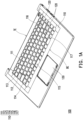
- FIG. 1A is a schematic perspective view of a modular frame according to an embodiment of the disclosure.
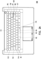
- FIG. 1B is a schematic top plan view of the modular frame of FIG. 1A .
- FIG. 1C is a schematic diagram showing processing of the modular frame of FIG. 1B where a punching process is adopted.
- FIG. 1D is a schematic diagram showing processing of the modular frame of FIG. 1B where a cutting process is adopted.
- a modular frame 100 of the disclosure includes a push-button area 110 and a plurality of rib structures 120.
- the push-button area 110 includes a function key hole group 111, an alphabet key hole group 112, a number key hole group 113, a shift key hole 114, a space key hole 115, a backspace key hole 116, and an enter key hole 117.
- the modular frame 100 is applicable to a keyboard of a notebook computer, and formats of the keyboard may be divided into US, UK, and JIS keyboard configurations.
- the modular frame may further include a touch area 130.
- the function key hole group 111 is disposed at a top end TE of the push-button area 110 and is presented in a long strip shape.
- the alphabet key hole group 112 is disposed at a middle of the push-button area 110.
- the number key hole group 113 is disposed between the function key hole group 111 and the alphabet key hole group 112.
- the shift key hole 114 is located at one side of the alphabet key hole group 112, and the shift key hole 114 includes a first processing region R1.
- the space key hole 115 is disposed at a bottom end BE of the push-button area 110 opposite to the function key hole group 111, and the space key hole 115 includes a second processing region R2, a third processing region R3, and a fourth processing region R4.
- the backspace key hole 116 is located between the function key hole group 111 and the alphabet key hole group 112 and at one side of the number key hole group 113, and the backspace key hole 116 includes a fifth processing region R5.
- the enter key hole 117 is located in the alphabet key hole group 112 and below the backspace key hole 116, and the enter key hole 117 includes a sixth processing region R6 and a seventh processing region R7.
- the rib structures 120 are selectively disposed in the first processing region R1 to the seventh processing region R7.
- the rib structures 120 may be formed in the first processing region R1 to the seventh processing region R7, respectively.
- each rib structure 120 may be integrally formed with each corresponding processing region (R1 to R7).
- the shift key hole 114 is divided into two sub-key holes; the space key hole 115 is divided into four sub-key holes, and the three rib structures 120 of the space key hole 115 are parallel to each other; the backspace key hole 116 is divided into two sub-key holes; and the enter key hole 117 is divided into three sub-key holes, and the two rib structures 120 in the enter key hole 117 are perpendicular to each other.
- the touch area 130 is adjacent to the bottom end BE of the push-button area 110, and the touch area 130 is configured to be mounted with a touch panel.
- the modular frame 100 of this embodiment includes a plurality of rib structures 120 integrally formed.
- the rib structures 120 formed in the first processing region R1 to the seventh processing region R7 may be selectively cut to switch the push-button area 110 to a first configuration (corresponding to a US keyboard configuration), a second configuration (corresponding to a UK keyboard configuration) or a third configuration (corresponding to a JIS keyboard configuration).
- a punching process or cutting process the redundant rib structures 120 are cut and removed from the push-button area 110, such that keys in the US, UK, and JIS keyboard configurations can be accommodated.
- a gap G is formed between each rib structure 120 and a top surface TS of the push-button area 110.
- the gap G prevents residual burrs on the top surface TS of the push-button area 110 after the rib structure 120 is cut.
- the push-button area 110 is placed on two inserts IP and the rib structure 120 to be cut is suspended between the two inserts IP. Then, a punch head PH is aligned with the rib structure 120 to be cut along a normal direction ND of the push-button area 110. Then, the punch head PH is activated to strike toward the rib structure 120 to be cut so as to cut the rib structure 120. After the cutting is completed, the push-button area 110 may be removed. Alternatively, another rib structure 120 to be cut may be suspended between the two inserts IP, and the above process may be repeated.
- the push-button area 110 is clamped by a vise VS, and the rib structure 120 to be cut is suspended between the vise VS.
- a knife KF is moved toward the rib structure 120 to be cut along the normal direction ND of the push-button area 110 so as to cut the rib structure 120.
- the push-button area 110 may be removed.
- another rib structure 120 to be cut may be suspended between the vise VS, and the above process may be repeated.
- FIG. 2A is a schematic top plan view of the modular frame of FIG. 1B switched to the first configuration.
- the rib structures 120 formed in the first processing region R1 to the sixth processing region R6 are cut through a punching or cutting process, to present the shift key hole 114, the space key hole 115, and the backspace key hole 116 each as a single key hole in a rectangular appearance, and present the enter key hole 117 as two sub-key holes by the rib structure 120 of the seventh processing region R7.
- FIG. 2B is a schematic top plan view of the modular frame of FIG. 1B switched to the second configuration.
- the rib structures 120 in the second processing region R2 to the fifth processing region R5 and the seventh processing region R7 are cut through a punching or cutting process, to present the space key hole 115 and the backspace key hole 116 each as a single key hole in a rectangular appearance, present the shift key hole 114 as two sub-key holes by the rib structure 120 of the first processing region R1, and present the enter key hole 117 as two sub-key holes by the rib structure 120 of the sixth processing region R6.
- FIG. 2C is a schematic top plan view of the modular frame of FIG. 1B switched to the third configuration.
- the two rib structures 120 formed in the first processing region R1 and the seventh processing region R7 are cut through a punching or cutting process, to present the shift key hole 114 as a single key hole in a rectangular appearance, and present the enter key hole 117 as two sub-key holes by the rib structure 120 of the sixth processing region R6.
- the space key hole 115 is divided into four sub-key holes by the three rib structures 120 in the second processing region R2 to the fourth processing region R4, and the backspace key hole 116 is presented as two sub-key holes by the rib structure 120 of the fifth processing region R5.
- FIG. 3A is a schematic top plan view of a modular frame according to another embodiment of the disclosure.
- FIG. 3B is a perspective view of the modular frame of FIG. 3A combined with a rib structure.
- FIG. 3C is a schematic diagram showing processing of the modular frame of FIG. 3B where a hot melt process is adopted.
- the modular frame 100A includes a push-button area 110a and at least one rib structure 120a.
- the push-button area 110a includes a function key hole group 111a, an alphabet key hole group 112a, a number key hole group 113a, a shift key hole 114a, a space key hole 115a, a backspace key hole 116a, and an enter key hole 117a.
- the modular frame 100A is applicable to a keyboard of a notebook computer, and formats of the keyboard may be divided into US, UK, and JIS keyboard configurations.
- the at least one rib structure 120a is selectively disposed in at least one of the first processing region R1 to the seventh processing region R7.
- the at least one rib structure 120a may be not integrally formed with each corresponding processing region (R1 to R7).
- the rib structure 120a is an external member and includes a plurality of rib structures, and the number of the rib structures depends on the requirements of the corresponding keyboard configuration.
- each of the at least one rib structure 120a includes two engaging portions 121a and two through holes TH, and at least one of the first processing region R1 to the seventh processing region R7 includes two positioning grooves PG and two hot melt pillars HP.
- each positioning groove PG is formed on a bottom surface BS of the push-button area 110a, and each hot melt pillar HP is disposed in each positioning groove PG.
- the two engaging portions 121a of each of the at least one of rib structure 120a are adapted to be disposed in the corresponding two positioning grooves PG and are rubbed and contacted by an inner wall IW.
- the two through holes TH are adapted to be sleeved on the corresponding two hot melt pillars HP.
- each hot melt pillar HP heat is transferred through an external heat source to each hot melt pillar HP, such that an end of each hot melt pillar HP passing through each through hole TH melts when heated, to adhere the at least one rib structure 120a to the push-button area 110a.
- the at least one rib structure 120a is fixed to at least one of the first processing region R1 to the seventh processing region R7, then switching the modular frame 100A to the first configuration (corresponding to the US keyboard configuration), the second configuration (corresponding to the UK keyboard configuration), or the third configuration (corresponding to the JIS keyboard configuration).
- the rib structure 120a since a melting point of the rib structure 120a is higher than a melting point of the hot melt pillar HP, the rib structure 120a remains in its original state during heating.
- FIG. 4A is a schematic top plan view of the modular frame of FIG. 3A switched to the first configuration.
- one rib structure 120a is disposed in the seventh processing region R7, to divide the enter key hole 117a into two sub-key holes by the rib structure 120a of the seventh processing region R7.
- the shift key hole 114a, the space key hole 115a, and the backspace key hole 116a each of them is presented as a single key hole in a rectangular appearance.
- FIG. 4B is a schematic top plan view of the modular frame of FIG. 3A to be switched to the second configuration.
- the at least one rib structure 120a when the modular frame 100a is switched to the second configuration (see FIG. 4B ), the at least one rib structure 120a includes two rib structures 120a respectively disposed in the first processing region R1 and the sixth processing region R6.
- the shift key hole 114a is divided into two sub-key holes by the rib structure 120a of the first processing region R1.
- the enter key hole 117a is divided into two sub-key holes by the rib structure 120a of the sixth processing region R6.
- the space key hole 115a and the backspace key hole 116a each of them is presented as a single key hole in a rectangular appearance.
- FIG. 4C is a schematic top plan view of the modular frame of FIG. 3A to be switched to the third configuration.
- the at least one rib structure 120a when the modular frame 100a is switched to the third configuration (see FIG. 4C ), the at least one rib structure 120a includes five rib structures 120a respectively disposed in the second processing region R2 to the sixth processing region R6.
- the space key hole 115a is divided into four sub-key holes by the rib structures 120a of the second processing region R2 to the fourth processing region R4.
- the backspace key hole 116a is divided into two sub-key holes by the rib structure 120a of the fifth processing region R5.
- the enter key hole 117a is divided into two sub-key holes by the rib structure 120 of the sixth processing region R6.
- the shift key hole 114a it is presented as a single key hole in a rectangular appearance.
- the modular frame of the disclosure includes the first processing region to the seventh processing region on which processes (such as a punching, cutting, or hot melt process) may be selectively performed to change the keyboard configuration.
- processes such as a punching, cutting, or hot melt process
- the rib structures formed in the first processing region to the seventh processing region are adapted to be selectively cut through a punching or cutting process, thereby switching the modular frame to the first configuration, the second configuration, or the third configuration, but the rib structure may also be selectively mounted in the first processing region to the seventh processing region, and multiple rib structures may be fixed to the corresponding first processing region to seventh processing region adopting a hot melt process, thereby switching the modular frame to the first configuration, the second configuration, or the third configuration.
Landscapes
- Engineering & Computer Science (AREA)
- Theoretical Computer Science (AREA)
- General Engineering & Computer Science (AREA)
- Computer Hardware Design (AREA)
- Human Computer Interaction (AREA)
- Physics & Mathematics (AREA)
- General Physics & Mathematics (AREA)
- Input From Keyboards Or The Like (AREA)
- Push-Button Switches (AREA)
Claims (7)
- Modularer Rahmen (100, 100A), umfassend:
einen Druckknopfbereich (110, 110a), umfassend:eine Funktionstasten-Lochgruppe (111, 111a), die an einem oberen Ende (TE) desDruckknopfbereichs (110, 110a) angeordnet ist;eine Buchstabentasten-Lochgruppe (112, 112a), die in der Mitte des Druckknopfbereichs (110, 110a) angeordnet ist;eine Zahlentasten-Lochgruppe (113, 113a), die zwischen der Funktionstasten-Lochgruppe (111, 111a) und der Buchstabentasten-Lochgruppe (112, 112a) angeordnet ist;ein Umschalt-Tastenloch (114, 114a), das sich an einer Seite der Buchstabentasten-Lochgruppe (112, 112a) befindet, wobei das Umschalt-Tastenloch (114, 114a) einen ersten Verarbeitungsbereich (R1) umfasst;ein Leertastenloch (115, 115a), das an einem unteren Ende (BE) des Druckknopfbereichs (110, 110a) gegenüber der Funktionstasten-Lochgruppe (111, 111a) angeordnet ist, wobei das Leertastenloch (115, 115a) einen zweiten Verarbeitungsbereich (R2), einen dritten Verarbeitungsbereich (R3) und einen vierten Verarbeitungsbereich (R4) umfasst;ein Backspace-Tastenloch (116, 116a), das sich zwischen der Funktionstasten-Lochgruppe (111, 111a) und der Buchstabentasten-Lochgruppe (112, 112a) und an einer Seite der Zahlentasten-Lochgruppe (113, 113a) befindet, wobei das Backspace-Tastenloch (116, 116a) einen fünften Verarbeitungsbereich (R5) umfasst; undein Eingabe-Tastenloch (117, 117a), das sich in der Buchstabentasten-Lochgruppe (112, 112a) und unterhalb des Backspace-Tastenlochs (116, 116a) befindet, wobei das Eingabe-Tastenloch (117, 117a) einen sechsten Verarbeitungsbereich (R6) und einen siebten Verarbeitungsbereich (R7) umfasst, wobei der modulare Rahmen (100, 100A) dadurch gekennzeichnet ist, dass er ferner umfasst:
eine Vielzahl von Rippenstrukturen (120, 120a), die selektiv in mindestens einem von dem ersten Verarbeitungsbereich (R1) bis zu dem siebten Verarbeitungsbereich (R7) angeordnet sind, um den modularen Rahmen (100, 100A) in eine erste Konfiguration, eine zweite Konfiguration oder eine dritte Konfiguration zu schalten,wobei jede der Rippenstrukturen (120, 120a) zwei eingreifende Abschnitte (121a) und zwei Durchgangslöcher (TH) umfasst und jeder des ersten Verarbeitungsbereichs (R1) bis zu dem siebten Verarbeitungsbereich (R7) zwei Positionierungsrillen (PG) und zwei Heißschmelzsäulen (HP) umfasst, die zwei eingreifenden Abschnitte (121a) jeder der Rippenstrukturen (120, 120a) angepasst sind, um in den entsprechenden zwei Positionierungsrillen (PG) angeordnet werden zu können, die zwei Heißschmelzsäulen (HP) angepasst sind, um durch die entsprechenden zwei Durchgangslöcher (TH) angeordnet werden zu können und jeder der Heißschmelzsäulen (HP) angepasst ist, um bei Erwärmung zu schmelzen, um jede der Rippenstrukturen an den Druckknopfbereich (110a) zu kleben. - Modularer Rahmen (100) gemäß Anspruch 1, wobei die Vielzahl von Rippenstrukturen (120) jeweils in dem ersten Verarbeitungsbereich (R1) bis zu dem siebten Verarbeitungsbereich (R7) angeordnet sind, wobei die Rippenstrukturen (120) das Umschalt-Tastenloch (114) in zwei Untertastenlöcher unterteilen, das Leertastenloch (115) in vier Untertastenlöcher unterteilen, das Backspace-Tastenloch (11 6) in zwei Unter-Tastenlöcher und das Eingabe-Tastenloch (117) in drei Unter-Tastenlöcher unterteilen.
- Modularer Rahmen (100) gemäß Anspruch 2, wobei zwischen jeder der Rippenstrukturen (120) und einer oberen Fläche (TS) des Druckknopfbereichs (110) ein Spalt (G) ausgebildet ist.
- Modularer Rahmen (100) gemäß Anspruch 2 oder 3, wobei zwei Rippenstrukturen (120) in dem Eingabe-Tastenloch (117) senkrecht zueinander sind.
- Modularer Rahmen (100A) wie in Anspruch 1 beschrieben, wobei in der ersten Konfiguration eine der Rippenstrukturen (120a) in dem siebten Bearbeitungsbereich (R7) angeordnet ist, um das Eingabe-Tastenloch (117a) in zwei Untertastenlöcher zu unterteilen.
- Modularer Rahmen (100A) gemäß Anspruch 1 oder 5, wobei in der zweiten Konfiguration die Vielzahl von Rippenstrukturen (120a) zwei Rippenstrukturen (120a) umfasst, die jeweils in dem ersten Bearbeitungsbereich (R1) und dem sechsten Bearbeitungsbereich (R6) angeordnet sind, um das Umschalt-Tastenloch (114, 114a) in zwei Untertastenlöcher zu unterteilen und das Eingabe-Tastenloch (117 a) in zwei Untertastenlöcher zu unterteilen.
- Modularer Rahmen (100A) gemäß Anspruch 1 oder 5 oder 6, wobei in der dritten Konfiguration die Vielzahl von Rippenstrukturen (120a) fünf Rippenstrukturen (120a) umfasst, die jeweils in dem zweiten Verarbeitungsbereich (R2) bis zu dem sechsten Verarbeitungsbereich (R6) angeordnet sind, um das Leertastenloch (115a) in vier Untertastenlöcher zu unterteilen, das Backspace-Tastenloch (116a) in zwei Untertastenlöcher und die Eingabetaste (117a) in zwei Untertastenlöcher zu unterteilen.
Applications Claiming Priority (1)
| Application Number | Priority Date | Filing Date | Title |
|---|---|---|---|
| TW109132511A TWI739605B (zh) | 2020-09-21 | 2020-09-21 | 模組化框架 |
Publications (3)
| Publication Number | Publication Date |
|---|---|
| EP3971679A1 EP3971679A1 (de) | 2022-03-23 |
| EP3971679C0 EP3971679C0 (de) | 2025-04-02 |
| EP3971679B1 true EP3971679B1 (de) | 2025-04-02 |
Family
ID=77465780
Family Applications (1)
| Application Number | Title | Priority Date | Filing Date |
|---|---|---|---|
| EP21189250.0A Active EP3971679B1 (de) | 2020-09-21 | 2021-08-03 | Modularer rahmen |
Country Status (5)
| Country | Link |
|---|---|
| US (1) | US11990293B2 (de) |
| EP (1) | EP3971679B1 (de) |
| JP (2) | JP7224397B2 (de) |
| CN (1) | CN114253403B (de) |
| TW (1) | TWI739605B (de) |
Families Citing this family (1)
| Publication number | Priority date | Publication date | Assignee | Title |
|---|---|---|---|---|
| US12321852B2 (en) * | 2020-12-26 | 2025-06-03 | International Business Machines Corporation | Filtering hidden matrix training DNN |
Family Cites Families (19)
| Publication number | Priority date | Publication date | Assignee | Title |
|---|---|---|---|---|
| US4564732A (en) * | 1982-05-19 | 1986-01-14 | Hi-Tek Corporation | Dovetail base assembly for keyswitches |
| US4688020A (en) * | 1984-05-14 | 1987-08-18 | United States Data Corporation | Reconfigurable keyboard |
| CN2470884Y (zh) * | 2001-02-08 | 2002-01-09 | 镇泓科技股份有限公司 | 模组化笔记型电脑 |
| US20020145847A1 (en) | 2001-04-04 | 2002-10-10 | Crosby Catherine K. | Portable computer |
| KR20020094804A (ko) * | 2001-06-13 | 2002-12-18 | 삼성전기주식회사 | 컴퓨터용 키보드 |
| US7850378B1 (en) * | 2005-05-13 | 2010-12-14 | Apple Inc. | Webbed keyboard assembly |
| JP4819771B2 (ja) | 2007-09-21 | 2011-11-24 | ミネベア株式会社 | キーボード装置、電子機器及びキーボード装置の製造方法 |
| TW201112053A (en) * | 2009-09-29 | 2011-04-01 | Inventec Corp | Keyboard module |
| CN102053706A (zh) | 2009-11-04 | 2011-05-11 | 宏碁股份有限公司 | 键盘模组组配结构 |
| TWM390487U (en) * | 2010-05-04 | 2010-10-11 | Acer Inc | Modular framework for chocolate keyboard |
| CN201622533U (zh) * | 2010-05-05 | 2010-11-03 | 宏碁股份有限公司 | 巧克力键盘的模块化框架 |
| US9064654B2 (en) * | 2012-03-02 | 2015-06-23 | Microsoft Technology Licensing, Llc | Method of manufacturing an input device |
| US9501105B2 (en) * | 2013-09-28 | 2016-11-22 | Intel Corporation | Keyboard for an electronic device |
| US20160307713A1 (en) * | 2015-04-20 | 2016-10-20 | Changshu Sunrex Technology Co., Ltd. | Keyboard device |
| JP2017076213A (ja) | 2015-10-14 | 2017-04-20 | 富士通株式会社 | 入力装置、電子機器、入力装置の製造方法 |
| JP6738021B2 (ja) | 2017-01-19 | 2020-08-12 | 富士通クライアントコンピューティング株式会社 | 情報処理装置および信号制御プログラム |
| US10620715B2 (en) * | 2017-03-20 | 2020-04-14 | International Business Machines Corporation | Programmatic, pluggable keyboard |
| CN111078024A (zh) * | 2018-10-19 | 2020-04-28 | 昆盈企业股份有限公司 | 动态调整键盘输出信号的方法 |
| CN111834155B (zh) * | 2020-01-02 | 2023-02-21 | 光宝电子(广州)有限公司 | 框体结构及键盘装置 |
-
2020
- 2020-09-21 TW TW109132511A patent/TWI739605B/zh active
-
2021
- 2021-06-02 CN CN202110612892.0A patent/CN114253403B/zh active Active
- 2021-06-18 JP JP2021102061A patent/JP7224397B2/ja active Active
- 2021-07-14 US US17/376,043 patent/US11990293B2/en active Active
- 2021-08-03 EP EP21189250.0A patent/EP3971679B1/de active Active
-
2022
- 2022-09-26 JP JP2022152745A patent/JP7371194B2/ja active Active
Also Published As
| Publication number | Publication date |
|---|---|
| TW202214069A (zh) | 2022-04-01 |
| CN114253403A (zh) | 2022-03-29 |
| JP7371194B2 (ja) | 2023-10-30 |
| JP7224397B2 (ja) | 2023-02-17 |
| JP2023002543A (ja) | 2023-01-10 |
| CN114253403B (zh) | 2024-09-13 |
| JP2022051674A (ja) | 2022-04-01 |
| EP3971679A1 (de) | 2022-03-23 |
| US20220093351A1 (en) | 2022-03-24 |
| US11990293B2 (en) | 2024-05-21 |
| EP3971679C0 (de) | 2025-04-02 |
| TWI739605B (zh) | 2021-09-11 |
Similar Documents
| Publication | Publication Date | Title |
|---|---|---|
| US8491209B2 (en) | Keyboard apparatus, electronic apparatus, and method of producing the keyboard apparatus | |
| US6706986B2 (en) | Scissors-like linkage structure, key switch including the structure and method of assembling the same | |
| US8689422B2 (en) | Securing plugs for attaching computer components | |
| US6311332B1 (en) | Hat having a window with replaceable patterns | |
| EP3971679B1 (de) | Modularer rahmen | |
| US9024217B2 (en) | Key structure of keyboard | |
| JP2008213342A (ja) | パネル | |
| US11158469B2 (en) | Framework structure and keyboard device | |
| US20120211340A1 (en) | Key structure with scissors-type connecting member | |
| JP2008181740A (ja) | ドームコンタクトフープとドームコンタクト製造方法 | |
| JP2006040699A (ja) | キースイッチ構造 | |
| CN207105109U (zh) | 改善组合公差的冲切模具 | |
| CN106024461B (zh) | 键盘组装治具 | |
| US11362659B2 (en) | Thin keyboard apparatus | |
| CN215037037U (zh) | 一种用于拆卸角度头的工装 | |
| JP5265901B2 (ja) | 金型 | |
| TWM633869U (zh) | 可更換刀片的刀架 | |
| JP2004039451A (ja) | ボタン部材およびボタンの組み付け方法 | |
| GB2403452A (en) | Keyboard having keys in alphabetic order | |
| TWM624371U (zh) | 鍵盤框架 | |
| JP4006600B2 (ja) | 形材 | |
| JP2003272470A (ja) | メンブレンスイッチ、メンブレンスイッチを使用したキースイッチ、キースイッチを備えたキーボード及びキーボードを備えたパーソナルコンピュータ | |
| EP1693736A2 (de) | Tastaturen für tragbare elektronische Vorrichtungen | |
| JP2009048859A (ja) | 操作キー、電子機器および操作キーの製造方法 | |
| JP2004186066A (ja) | キーボード |
Legal Events
| Date | Code | Title | Description |
|---|---|---|---|
| PUAI | Public reference made under article 153(3) epc to a published international application that has entered the european phase |
Free format text: ORIGINAL CODE: 0009012 |
|
| STAA | Information on the status of an ep patent application or granted ep patent |
Free format text: STATUS: THE APPLICATION HAS BEEN PUBLISHED |
|
| AK | Designated contracting states |
Kind code of ref document: A1 Designated state(s): AL AT BE BG CH CY CZ DE DK EE ES FI FR GB GR HR HU IE IS IT LI LT LU LV MC MK MT NL NO PL PT RO RS SE SI SK SM TR |
|
| STAA | Information on the status of an ep patent application or granted ep patent |
Free format text: STATUS: REQUEST FOR EXAMINATION WAS MADE |
|
| 17P | Request for examination filed |
Effective date: 20220812 |
|
| RBV | Designated contracting states (corrected) |
Designated state(s): AL AT BE BG CH CY CZ DE DK EE ES FI FR GB GR HR HU IE IS IT LI LT LU LV MC MK MT NL NO PL PT RO RS SE SI SK SM TR |
|
| STAA | Information on the status of an ep patent application or granted ep patent |
Free format text: STATUS: EXAMINATION IS IN PROGRESS |
|
| 17Q | First examination report despatched |
Effective date: 20230605 |
|
| GRAP | Despatch of communication of intention to grant a patent |
Free format text: ORIGINAL CODE: EPIDOSNIGR1 |
|
| STAA | Information on the status of an ep patent application or granted ep patent |
Free format text: STATUS: GRANT OF PATENT IS INTENDED |
|
| INTG | Intention to grant announced |
Effective date: 20241108 |
|
| GRAS | Grant fee paid |
Free format text: ORIGINAL CODE: EPIDOSNIGR3 |
|
| GRAA | (expected) grant |
Free format text: ORIGINAL CODE: 0009210 |
|
| STAA | Information on the status of an ep patent application or granted ep patent |
Free format text: STATUS: THE PATENT HAS BEEN GRANTED |
|
| AK | Designated contracting states |
Kind code of ref document: B1 Designated state(s): AL AT BE BG CH CY CZ DE DK EE ES FI FR GB GR HR HU IE IS IT LI LT LU LV MC MK MT NL NO PL PT RO RS SE SI SK SM TR |
|
| REG | Reference to a national code |
Ref country code: GB Ref legal event code: FG4D |
|
| REG | Reference to a national code |
Ref country code: CH Ref legal event code: EP |
|
| REG | Reference to a national code |
Ref country code: IE Ref legal event code: FG4D |
|
| U01 | Request for unitary effect filed |
Effective date: 20250402 |
|
| U07 | Unitary effect registered |
Designated state(s): AT BE BG DE DK EE FI FR IT LT LU LV MT NL PT RO SE SI Effective date: 20250408 |
|
| U20 | Renewal fee for the european patent with unitary effect paid |
Year of fee payment: 5 Effective date: 20250717 |
|
| PG25 | Lapsed in a contracting state [announced via postgrant information from national office to epo] |
Ref country code: ES Free format text: LAPSE BECAUSE OF FAILURE TO SUBMIT A TRANSLATION OF THE DESCRIPTION OR TO PAY THE FEE WITHIN THE PRESCRIBED TIME-LIMIT Effective date: 20250402 |
|
| PG25 | Lapsed in a contracting state [announced via postgrant information from national office to epo] |
Ref country code: NO Free format text: LAPSE BECAUSE OF FAILURE TO SUBMIT A TRANSLATION OF THE DESCRIPTION OR TO PAY THE FEE WITHIN THE PRESCRIBED TIME-LIMIT Effective date: 20250702 Ref country code: GR Free format text: LAPSE BECAUSE OF FAILURE TO SUBMIT A TRANSLATION OF THE DESCRIPTION OR TO PAY THE FEE WITHIN THE PRESCRIBED TIME-LIMIT Effective date: 20250703 |
|
| PG25 | Lapsed in a contracting state [announced via postgrant information from national office to epo] |
Ref country code: PL Free format text: LAPSE BECAUSE OF FAILURE TO SUBMIT A TRANSLATION OF THE DESCRIPTION OR TO PAY THE FEE WITHIN THE PRESCRIBED TIME-LIMIT Effective date: 20250402 |
|
| PG25 | Lapsed in a contracting state [announced via postgrant information from national office to epo] |
Ref country code: HR Free format text: LAPSE BECAUSE OF FAILURE TO SUBMIT A TRANSLATION OF THE DESCRIPTION OR TO PAY THE FEE WITHIN THE PRESCRIBED TIME-LIMIT Effective date: 20250402 |
|
| PG25 | Lapsed in a contracting state [announced via postgrant information from national office to epo] |
Ref country code: RS Free format text: LAPSE BECAUSE OF FAILURE TO SUBMIT A TRANSLATION OF THE DESCRIPTION OR TO PAY THE FEE WITHIN THE PRESCRIBED TIME-LIMIT Effective date: 20250702 |
|
| PG25 | Lapsed in a contracting state [announced via postgrant information from national office to epo] |
Ref country code: IS Free format text: LAPSE BECAUSE OF FAILURE TO SUBMIT A TRANSLATION OF THE DESCRIPTION OR TO PAY THE FEE WITHIN THE PRESCRIBED TIME-LIMIT Effective date: 20250802 |
|
| PG25 | Lapsed in a contracting state [announced via postgrant information from national office to epo] |
Ref country code: SM Free format text: LAPSE BECAUSE OF FAILURE TO SUBMIT A TRANSLATION OF THE DESCRIPTION OR TO PAY THE FEE WITHIN THE PRESCRIBED TIME-LIMIT Effective date: 20250402 |
|
| PG25 | Lapsed in a contracting state [announced via postgrant information from national office to epo] |
Ref country code: CZ Free format text: LAPSE BECAUSE OF FAILURE TO SUBMIT A TRANSLATION OF THE DESCRIPTION OR TO PAY THE FEE WITHIN THE PRESCRIBED TIME-LIMIT Effective date: 20250402 |
|
| PG25 | Lapsed in a contracting state [announced via postgrant information from national office to epo] |
Ref country code: SK Free format text: LAPSE BECAUSE OF FAILURE TO SUBMIT A TRANSLATION OF THE DESCRIPTION OR TO PAY THE FEE WITHIN THE PRESCRIBED TIME-LIMIT Effective date: 20250402 |
|
| PLBE | No opposition filed within time limit |
Free format text: ORIGINAL CODE: 0009261 |
|
| STAA | Information on the status of an ep patent application or granted ep patent |
Free format text: STATUS: NO OPPOSITION FILED WITHIN TIME LIMIT |
|
| REG | Reference to a national code |
Ref country code: CH Ref legal event code: L10 Free format text: ST27 STATUS EVENT CODE: U-0-0-L10-L00 (AS PROVIDED BY THE NATIONAL OFFICE) Effective date: 20260211 |