EP3970592B1 - System zum beladen einer spülmaschine, greifersystem für eine beladeanordnung zum beladen einer spülmaschine sowie spülmaschine - Google Patents
System zum beladen einer spülmaschine, greifersystem für eine beladeanordnung zum beladen einer spülmaschine sowie spülmaschine Download PDFInfo
- Publication number
- EP3970592B1 EP3970592B1 EP21172049.5A EP21172049A EP3970592B1 EP 3970592 B1 EP3970592 B1 EP 3970592B1 EP 21172049 A EP21172049 A EP 21172049A EP 3970592 B1 EP3970592 B1 EP 3970592B1
- Authority
- EP
- European Patent Office
- Prior art keywords
- gripper
- gripping
- parallel
- parallel gripper
- clamping jaw
- Prior art date
- Legal status (The legal status is an assumption and is not a legal conclusion. Google has not performed a legal analysis and makes no representation as to the accuracy of the status listed.)
- Active
Links
Images

Classifications
-
- A—HUMAN NECESSITIES
- A47—FURNITURE; DOMESTIC ARTICLES OR APPLIANCES; COFFEE MILLS; SPICE MILLS; SUCTION CLEANERS IN GENERAL
- A47L—DOMESTIC WASHING OR CLEANING; SUCTION CLEANERS IN GENERAL
- A47L15/00—Washing or rinsing machines for crockery or tableware
- A47L15/26—Washing or rinsing machines for crockery or tableware with movement of the crockery baskets by other means
-
- A—HUMAN NECESSITIES
- A47—FURNITURE; DOMESTIC ARTICLES OR APPLIANCES; COFFEE MILLS; SPICE MILLS; SUCTION CLEANERS IN GENERAL
- A47L—DOMESTIC WASHING OR CLEANING; SUCTION CLEANERS IN GENERAL
- A47L15/00—Washing or rinsing machines for crockery or tableware
- A47L15/24—Washing or rinsing machines for crockery or tableware with movement of the crockery baskets by conveyors
- A47L15/241—Washing or rinsing machines for crockery or tableware with movement of the crockery baskets by conveyors the dishes moving in a horizontal plane
- A47L15/245—Washing or rinsing machines for crockery or tableware with movement of the crockery baskets by conveyors the dishes moving in a horizontal plane the dishes being placed directly on the conveyors, i.e. not in dish racks
-
- A—HUMAN NECESSITIES
- A47—FURNITURE; DOMESTIC ARTICLES OR APPLIANCES; COFFEE MILLS; SPICE MILLS; SUCTION CLEANERS IN GENERAL
- A47L—DOMESTIC WASHING OR CLEANING; SUCTION CLEANERS IN GENERAL
- A47L15/00—Washing or rinsing machines for crockery or tableware
- A47L15/24—Washing or rinsing machines for crockery or tableware with movement of the crockery baskets by conveyors
- A47L15/241—Washing or rinsing machines for crockery or tableware with movement of the crockery baskets by conveyors the dishes moving in a horizontal plane
-
- A—HUMAN NECESSITIES
- A47—FURNITURE; DOMESTIC ARTICLES OR APPLIANCES; COFFEE MILLS; SPICE MILLS; SUCTION CLEANERS IN GENERAL
- A47L—DOMESTIC WASHING OR CLEANING; SUCTION CLEANERS IN GENERAL
- A47L15/00—Washing or rinsing machines for crockery or tableware
- A47L15/24—Washing or rinsing machines for crockery or tableware with movement of the crockery baskets by conveyors
- A47L15/247—Details specific to conveyor-type machines, e.g. curtains
-
- A—HUMAN NECESSITIES
- A47—FURNITURE; DOMESTIC ARTICLES OR APPLIANCES; COFFEE MILLS; SPICE MILLS; SUCTION CLEANERS IN GENERAL
- A47L—DOMESTIC WASHING OR CLEANING; SUCTION CLEANERS IN GENERAL
- A47L15/00—Washing or rinsing machines for crockery or tableware
- A47L15/42—Details
-
- A—HUMAN NECESSITIES
- A47—FURNITURE; DOMESTIC ARTICLES OR APPLIANCES; COFFEE MILLS; SPICE MILLS; SUCTION CLEANERS IN GENERAL
- A47L—DOMESTIC WASHING OR CLEANING; SUCTION CLEANERS IN GENERAL
- A47L15/00—Washing or rinsing machines for crockery or tableware
- A47L15/42—Details
- A47L15/50—Racks ; Baskets
- A47L15/502—Cutlery baskets
-
- B—PERFORMING OPERATIONS; TRANSPORTING
- B25—HAND TOOLS; PORTABLE POWER-DRIVEN TOOLS; MANIPULATORS
- B25J—MANIPULATORS; CHAMBERS PROVIDED WITH MANIPULATION DEVICES
- B25J11/00—Manipulators not otherwise provided for
- B25J11/008—Manipulators for service tasks
-
- B—PERFORMING OPERATIONS; TRANSPORTING
- B25—HAND TOOLS; PORTABLE POWER-DRIVEN TOOLS; MANIPULATORS
- B25J—MANIPULATORS; CHAMBERS PROVIDED WITH MANIPULATION DEVICES
- B25J11/00—Manipulators not otherwise provided for
- B25J11/008—Manipulators for service tasks
- B25J11/0085—Cleaning
-
- B—PERFORMING OPERATIONS; TRANSPORTING
- B25—HAND TOOLS; PORTABLE POWER-DRIVEN TOOLS; MANIPULATORS
- B25J—MANIPULATORS; CHAMBERS PROVIDED WITH MANIPULATION DEVICES
- B25J15/00—Gripping heads and other end effectors
- B25J15/0009—Gripping heads and other end effectors comprising multi-articulated fingers, e.g. resembling a human hand
-
- B—PERFORMING OPERATIONS; TRANSPORTING
- B25—HAND TOOLS; PORTABLE POWER-DRIVEN TOOLS; MANIPULATORS
- B25J—MANIPULATORS; CHAMBERS PROVIDED WITH MANIPULATION DEVICES
- B25J15/00—Gripping heads and other end effectors
- B25J15/0023—Gripper surfaces directly activated by a fluid
-
- B—PERFORMING OPERATIONS; TRANSPORTING
- B25—HAND TOOLS; PORTABLE POWER-DRIVEN TOOLS; MANIPULATORS
- B25J—MANIPULATORS; CHAMBERS PROVIDED WITH MANIPULATION DEVICES
- B25J15/00—Gripping heads and other end effectors
- B25J15/02—Gripping heads and other end effectors servo-actuated
- B25J15/0253—Gripping heads and other end effectors servo-actuated comprising parallel grippers
-
- B—PERFORMING OPERATIONS; TRANSPORTING
- B25—HAND TOOLS; PORTABLE POWER-DRIVEN TOOLS; MANIPULATORS
- B25J—MANIPULATORS; CHAMBERS PROVIDED WITH MANIPULATION DEVICES
- B25J15/00—Gripping heads and other end effectors
- B25J15/08—Gripping heads and other end effectors having finger members
- B25J15/12—Gripping heads and other end effectors having finger members with flexible finger members
-
- A—HUMAN NECESSITIES
- A47—FURNITURE; DOMESTIC ARTICLES OR APPLIANCES; COFFEE MILLS; SPICE MILLS; SUCTION CLEANERS IN GENERAL
- A47L—DOMESTIC WASHING OR CLEANING; SUCTION CLEANERS IN GENERAL
- A47L15/00—Washing or rinsing machines for crockery or tableware
- A47L15/0076—Washing or rinsing machines for crockery or tableware of non-domestic use type, e.g. commercial dishwashers for bars, hotels, restaurants, canteens or hospitals
-
- A—HUMAN NECESSITIES
- A47—FURNITURE; DOMESTIC ARTICLES OR APPLIANCES; COFFEE MILLS; SPICE MILLS; SUCTION CLEANERS IN GENERAL
- A47L—DOMESTIC WASHING OR CLEANING; SUCTION CLEANERS IN GENERAL
- A47L2401/00—Automatic detection in controlling methods of washing or rinsing machines for crockery or tableware, e.g. information provided by sensors entered into controlling devices
- A47L2401/04—Crockery or tableware details, e.g. material, quantity, condition
-
- A—HUMAN NECESSITIES
- A47—FURNITURE; DOMESTIC ARTICLES OR APPLIANCES; COFFEE MILLS; SPICE MILLS; SUCTION CLEANERS IN GENERAL
- A47L—DOMESTIC WASHING OR CLEANING; SUCTION CLEANERS IN GENERAL
- A47L2501/00—Output in controlling method of washing or rinsing machines for crockery or tableware, i.e. quantities or components controlled, or actions performed by the controlling device executing the controlling method
- A47L2501/36—Other output
Definitions
- the present invention relates generally to the field of commercial dishwashing.
- the invention relates to a system for loading a dishwasher, which is designed as a commercial conveyor dishwasher.
- the publication US 2019/375114 A1 relates to a gripper system according to the preamble of claim 1 with a parallel gripper that has two clamping jaws between which a gripping area of the parallel gripper is defined.
- One of the two clamping jaws is segmented in such a way that the clamping jaw can be adapted at least in some areas to a surface contour of a part of the washware to be gripped by the parallel gripper.
- Conveyor warewashers are used in commercial areas. In contrast to household dishwashers, in which the items to be cleaned remain stationary in the machine during cleaning, conveyor dishwashers transport the items to be cleaned through various treatment zones of the machine.
- the wash ware (wash items), such as trays, dishes, pots, glasses, cutlery and other utensils to be cleaned, are passed through several treatment zones, such as pre-wash zone(s), main wash zone(s), Post-wash or pre-wash zone(s), final rinse zone(s) and drying zone(s).
- a transport device is used to transport wash items in one transport direction through the conveyor dishwasher, which usually has compartments for holding wash items.
- the compartments can be formed by support fingers on a conveyor belt of the transport device.
- dish baskets serve as the transport device, in which compartments can be formed to hold the wash items to be treated. It is conceivable that the dish baskets are transported through the rack conveyor dishwasher using a conveyor device.
- the items to be cleaned are pre-sorted before being placed on the conveyor belt.
- the publication US6,530,996 B2 A basket transport dishwasher is known in which the items to be washed are pre-sorted in dish baskets and fed to the respective treatment zones.
- Conveyor dishwashers are used in large establishments such as cafeterias and canteens in particular to clean large quantities of dirty dishes as economically as possible. Conveyor dishwashers of the type currently known can clean several hundred place settings per hour. Studies have shown that on average each place setting usually consists of a tray, a plate, one or two bowls, a drinking glass and a set of cutlery.
- the place setting sets are transported from the return station to the dishwashing area.
- the place setting sets are usually transported using a corresponding feed conveyor belt.
- the place setting set is transported from the return station to the dishwashing area using a conveyor belt directly to a loading area of the conveyor dishwasher.
- the items to be washed are usually removed manually by the operating personnel and sorted into the conveyor belt of the conveyor dishwasher.
- pre-sorting is usually done in such a way that the set of dishes and cutlery is manually removed by the operating staff from a tray to be cleaned and the tray is then stacked in front of the conveyor device or in the inlet area (dirty side) of the conveyor dishwasher.
- the trays from this stack of trays are placed into the conveyor belt of the conveyor dishwasher from time to time and cleaned according to type.
- This method of sorting has the advantage that trays cannot cast a spray shadow on smaller items of washware stacked behind the trays. Furthermore, this method makes the stacking and destacking process much simpler and more efficient than if the items to be washed were mixed with the trays to be cleaned.
- each tray must incorporate into his or her work process twice at the machine inlet: the first time when removing the cutlery and crockery from the tray to be cleaned, and the second time when actually placing the trays into the conveyor belt of the conveyor dishwasher.
- the present invention is based on the object of providing a solution for a conveyor dishwasher of the aforementioned type, in which it is possible to make the entire washing and rinsing process more efficient, whereby in particular the working time of the dishwasher staff can be shortened and the resource consumption of the dishwasher can be reduced.
- the invention relates in particular to a system for the preferably automatic or at least partially automatic loading of a conveyor dishwasher, in particular a commercial conveyor dishwasher, wherein the loading system according to the invention has a feed conveyor belt for feeding items to be washed to a loading area of the conveyor dishwasher and a loading arrangement for the preferably automatic loading of the conveyor dishwasher with items to be washed.
- the loading arrangement has a gripper system with at least one parallel gripper, wherein the at least one parallel gripper has at least two clamping jaws, between which a gripping area of the parallel gripper is defined.
- EOAT devices usually have at least two tong-shaped pivoting grippers. or gripping jaws that can be moved linearly against each other along suitable guides, which grasp and clamp an object or part/workpiece to be gripped from opposite sides with gripping surfaces facing each other.
- Such EOAT devices therefore fulfil the function of grasping and holding and establish the connection between a robot arm and the workpiece/object/part.
- the decisive factors for a secure connection are the type of active pairing and the number of contact levels.
- the active pairing can be achieved through force, shape or material pairing.
- the hold is created by exerting pressure on the workpiece surface.
- form pairing the holding takes place via an enclosure of the same shape around the workpiece.
- gripper systems with parallel grippers may be generally known from the manufacturing industry, especially in assembly, such gripper systems cannot be used, or at least not without further ado, as part of a loading arrangement for the preferably automatic loading of a dishwasher with items to be washed.
- conventional gripper systems designed as EOAT devices are specially designed, particularly with regard to the shape and the position and orientation of the item to be gripped.
- conventional gripper systems designed as EOAT devices are generally used during assembly to grasp predetermined items of a certain size and shape at a certain, predetermined gripping position in order to then place the item to be gripped at another, predetermined position.
- the gripper system is designed particularly with regard to the item to be gripped, particularly with regard to the size, shape and material of the item to be gripped.
- the loading arrangement has a gripper system with at least one parallel gripper, wherein the at least one parallel gripper has at least two clamping jaws or gripping fingers, between which a gripping area of the parallel gripper is defined.
- the invention provides that at least one of the at least two clamping jaws/gripping fingers of the parallel gripper is segmented in such a way that the at least one clamping jaw/the at least one gripping finger can be adapted at least in some areas to a surface contour of a washware item to be gripped by the at least one parallel gripper.
- the loading system according to the invention is therefore suitable for the preferably automatic or at least partially automatic loading of a conveyor dishwasher, in particular a commercial one.
- the parallel gripper has at least one clamping jaw or at least one gripping finger, which can be adapted at least in part to a surface contour of a piece of dishware to be gripped by the parallel gripper, the parallel gripper can reliably fulfil the function of grasping and holding different pieces of dishware.
- a secure connection between the parallel gripper and the item to be manipulated is possible due to the type of effective pairing that can be achieved and the number of contact levels that can be achieved with the parallel gripper.
- the effective pairing is achieved in particular through a combination of force and shape pairing.
- the parallel gripper holds the item to be washed by exerting pressure on the surface of the item to be washed.
- the item to be washed is held by enclosing the item to be washed, particularly in certain areas, in an identically shaped manner.
- a parallel gripper that can be operated with an electric motor drive is deliberately proposed as an effector for the gripper system of the loading arrangement, although such electric motor-operated parallel grippers are rather unusual in gripper technology for gripping and manipulating gripping items. Rather, in gripper technology, primarily pneumatically operated effectors, in particular in the form of so-called suction grippers, are proposed for handling gripping items.
- a suction gripper generally has at least one flexible suction cup that defines a suction chamber that can be connected to a vacuum source and has a front end area that borders a suction opening and an opposite rear end area.
- the suction opening of the suction cup is generally formed with a sealing lip that rests or can be placed on the surface of the object to be handled and then encloses a suction chamber between the suction cup and the surface of the object, which can be evacuated accordingly. This means that the suction cup lies tightly against the surface of the object and holds it pneumatically.
- suction grippers are not suitable for handling items to be washed, since there is a risk, particularly when handling dirty items to be washed, that food residues etc. that are on the items to be handled, such as plates and bowls, will clog the vacuum lines pneumatically connected to the suction chamber when the suction chamber is evacuated, so that a secure gripping of the items to be washed is no longer guaranteed.
- Pneumatically operated grippers are also known from gripper technology.
- a further disadvantage of the pneumatically operated grippers known from gripper technology is that they require compressed air as an operating medium, which is usually not available in dishwashing areas.
- pneumatically operated grippers usually only allow two positions, namely the open position and the closed position, which prevents pneumatically operated grippers from being used for a variety of different types of washware, in particular of different sizes and/or different shapes.
- an electric motor-operated parallel gripper is preferably proposed as the effector for automatically loading the conveyor dishwasher with items to be washed.
- the associated clamping jaws/gripper fingers can be adjusted at least partially as desired over a gripping range of the parallel gripper using an electric motor drive.
- a further advantage of using an electric motor-operated parallel gripper is that the effector designed as a parallel gripper can be designed with a self-locking mechanism in a simple manner, so that it holds the gripped item of washware in the tension-free state without going into an open position.
- the invention is not limited to parallel grippers whose clamping jaws/gripper fingers are adjustable using an electric motor drive. Rather, the present invention generally relates to parallel grippers whose clamping jaws are automatically adjustable - however they are adjusted.
- the manual handling steps required to load the conveyor dishwasher can be significantly reduced, since the gripper system efficiently not only handles plates, but also bowls or glasses or other items to be washed can be automatically sorted into the conveyor dishwasher.
- the loading system according to the invention ensures that the conveyor dishwasher is operated as ergonomically and user-friendly as possible, since manual loading of the items to be washed, and in particular of plates or cups or bowls, into the conveyor dishwasher is no longer necessary.
- the cleaning result of the dishwasher can be improved with the loading system according to the invention, since with the aid of the loading arrangement all the wash items of a specified or definable wash item group can be automatically sorted uniformly on a correspondingly assigned conveyor belt or a correspondingly assigned conveyor track of a conveyor dishwasher.
- the unloading process can be simplified because each group of items to be washed can be transported through the conveyor dishwasher on a defined conveyor track or conveyor belt and thus arrives at the conveyor dishwasher's unloading area already pre-sorted.
- the loading system according to the invention has an item to be washed detector device which serves to detect the type of items to be washed (plates, cups, bowls, etc.) fed via the feed conveyor belt and then to use the at least one parallel gripper to specifically lift a certain type of item to be washed from the feed conveyor belt and sort it into a corresponding transport track of a conveyor dishwasher.
- washware detector device refers to any detection device that is designed to detect or determine the type of washware fed via the feed conveyor belt. It is particularly conceivable that the washware detector device has at least one Has a detector device with which the size, shape and/or material of the items to be washed fed via the feed conveyor belt can be detected.
- the washware detector device can have at least one detector device that preferably operates optically inductively or capacitively, so that the size, shape and/or material of the corresponding washware item can be detected in order to identify the type of washware.
- detectors can also be used as detector devices, such as inductively operating proximity sensors, light sensors, light curtains, laser scanners, 3D lasers, cameras, rotary encoders, etc.
- the gripper system of the loading arrangement has at least one parallel gripper ensures that - with the exception of cutlery items - almost all other types of items to be washed can be manipulated accordingly, i.e. in particular they can be removed from the feed conveyor belt and sorted into a preferably pre-determined transport track of a conveyor dishwasher.
- the operating principle of parallel grippers is based on the fact that they have at least two clamping jaws/two gripping fingers that can be moved relative to each other in a linear movement.
- at least one of the at least two clamping jaws/gripping fingers of the parallel gripper can be moved or driven by a type of "plunger piston".
- a linear drive as the electric motor drive.
- a torque generated by an electric motor drive as required can be transmitted to the at least one clamping jaw/the at least one gripping finger via a gear arrangement.
- embodiments of the present invention provide that the gripper system or the at least one parallel gripper belonging to the gripper system is provided with a sensor system with which the correct relative position of a piece of washware to the gripping area of the parallel gripper and the presence of a piece of washware can be detected. or can be recognized, correct manipulation of the item to be washed by the parallel gripper can be checked, or corresponding processing parameters can be checked.
- At least one of the at least two clamping jaws of the parallel gripper is segmented.
- the at least one (segmented) clamping jaw consists of at least two sections (segments) which are movable and in particular pivotable relative to one another. This subdivision allows the (segmented) clamping jaw to be variably adapted to the surface contour of a part of the washware to be gripped by the at least one parallel gripper.
- a finer segmentation of at least one clamping jaw is advantageous so that this item to be washed can be manipulated with the help of the parallel gripper mainly via shape pairing.
- the invention is not limited to parallel grippers in which at least one clamping jaw is segmented into more than two sections.
- the at least two segments of the segmented clamping jaw are connected via a joint region and in particular a pivot region such that the segments or at least one of the segments of the at least one segmented clamping jaw can be moved and in particular pivoted, in particular as required, in the direction of the gripping region and/or in the opposite direction.
- the at least one parallel gripper of the gripper system of the loading arrangement has a gripper housing in which a drive for at least one of the at least two clamping jaws of the parallel gripper is accommodated or can be accommodated at least in some areas.
- a slide element that is movable and in particular displaceable relative to the gripper housing is assigned to the drive.
- the at least one segmented clamping jaw of the parallel gripper is connected to the gripper housing movable and in particular displaceable carriage element is movable and in particular displaceable relative to the housing.
- the parallel gripper has a clamping jaw, which is designed in particular as a gripping finger and is rigidly connected to the gripper housing.
- the expression "rigidly connected to the gripper housing” means that this clamping jaw, which is designed in particular as a gripping finger, is not moved and in particular is not displaced relative to the gripper housing when the carriage element is actuated.
- each clamping jaw of the parallel gripper is assigned a slide element, so that, if required, each clamping jaw is movable and in particular displaceable relative to the gripper housing and relative to the other clamping jaws.
- the at least two clamping jaws of the parallel gripper have a self-centering function.
- the parallel gripper has at least two and preferably exactly two clamping jaws, designed in particular as gripping fingers, which are each rigidly connected to the gripper housing and which are arranged next to one another on a line running perpendicular to the direction of movement of the carriage element.
- This easy-to-implement implementation of the parallel gripper ensures that a piece of dishware is gripped by the clamping jaws of the parallel gripper via a three-point bearing. Because at least the segmented clamping jaw of the parallel gripper can be moved relative to the other clamping jaws designed as gripping fingers and relative to the piece of dishware to be gripped by the gripper system, a self-centering function can be automatically implemented.
- the at least one parallel gripper has a gripper housing in which at least partially a drive for at least one of the at least two clamping jaws of the parallel gripper is received or can be received, wherein the drive is assigned a slide element that is movable and in particular displaceable relative to the gripper housing.
- the at least one segmented clamping jaw is rigidly connected to the gripper housing, while at least one further clamping jaw of the parallel gripper, which is preferably designed as a gripping finger, is movable and in particular displaceable with the slide element relative to the gripper housing.
- the parallel gripper has at least two and preferably exactly two further clamping jaws, designed in particular as gripping fingers, which are each movable and in particular displaceable with the slide element relative to the gripper housing, wherein the at least two and preferably exactly two further clamping jaws designed as gripping fingers are arranged next to one another on a line running perpendicular to the direction of movement of the slide element.
- the at least one segmented clamping jaw is designed as an angle gripper and in particular as a single-finger angle gripper with one gripping finger, wherein the gripping finger of the angle gripper can be pivoted into the gripping area of the parallel gripper and pivoted out of the gripping area of the parallel gripper as required.
- the gripping finger of the angle gripper has several segments/gripping fingers that can be pivoted relative to one another via a joint area.
- the last-mentioned design variants in which the at least one segmented clamping jaw is designed as an angle gripper and in particular as a single-finger angle gripper with one gripping finger, are in principle a hybrid solution, namely a combination of a parallel gripper and an angle gripper.
- This hybrid solution significantly expands the application area of the parallel gripper, since the parallel gripper can be used to grip different Types of washware items and especially washware items with different surface contours can be reliably detected.
- the angle gripper preferably has a first segment/a first area which is either rigidly connected to the gripper housing of the parallel gripper or can be moved relative to the gripper housing of the parallel gripper in the direction of the gripping area or in the opposite direction via the slide element of the parallel gripper.
- a pivotably articulated gripper finger (second segment) is provided on this first segment, which is operatively coupled to a drive associated with the angle gripper in such a way that it can be pivoted selectively and preferably variably between a first position, for example parallel to the gripping area of the parallel gripper, and a second position, in particular obliquely or transversely to the first position in the direction of the gripping area by actuating the drive.
- the at least one segmented clamping jaw of the at least one parallel gripper is designed such that by applying fluid and preferably compressed air to at least one compressed air chamber, which is preferably formed at least in part in the segmented clamping jaw, at least one segment of the segmented clamping jaw is movable and in particular pivotable, in particular as required, in the direction of the gripping area and/or in the opposite direction.
- a sensor is provided on the gripping finger of the angle gripper, which detects the deflection of the gripping finger relative to the first segment of the angle gripper and/or detects a pressure exerted by the gripping finger on a piece of washware.
- the at least one segmented clamping jaw has a region which is prestressed in the direction of the gripping region of the parallel gripper, in particular an elastic and preferably spring-elastic region, which presses against the prestress against the part of the item to be washed when gripping a part of the item to be washed.
- an optimal shape pairing can be achieved, namely for items to be washed of a large number of different types, wherein at the same time, by adjusting the pre-tensioning force of the elastic region, a maximum holding force acting on the item to be washed can be adjusted or limited.
- the pre-tensioned region of the segmented clamping jaw has, at least in some regions, a convex shape with respect to the gripping region of the parallel gripper.
- the clamping jaws of the parallel gripper are at least partially covered with an elastic material.
- the clamping jaws of the parallel gripper are at least partially covered with an elastomer.
- Hydrogenated acrylonitrile butadiene rubber HNBR can also be used as an elastic material.
- HNBR material has the advantage that it is very inert due to the lack of double bonds. This increases the durability of the material. HNBR material is also relatively temperature-resistant, which means that the clamping jaws coated with HNBR can be operated at temperatures up to 150°C, for example, or can be brought into contact with items to be washed that have a temperature of up to 150°C.
- the elastic material is vulcanized onto the clamping jaws or that the clamping jaws are formed with the elastic material by an injection molding process.
- Vulcanization means in particular that an intermediate layer is provided between the elastic material and the material of the clamping jaw.
- the intermediate layer is a suitable binding agent to enable a firm connection between the elastic material and the material of the clamping jaw and in particular to prevent the elastic material from becoming porous.
- an injection molding process is preferably used, whereby the clamping jaw is introduced into a mold and the elastic material is poured into the mold in a fluid state so that the elastic material fills a cavity between the injection mold and the clamping jaw. The elastic material then hardens in the mold. The mold can then be removed and the clamping jaw formed by the elastic material can be removed.
- the clamping jaws of the parallel gripper each have at least one transverse bore.
- the at least one transverse bore in the area of the clamping jaws ensures that the hold of the elastic material is improved when the clamping jaws are covered with the elastic material.
- the hold of the elastic material on the clamping jaws is improved compared to a case in which the clamping jaws are not further structured or modified, i.e. are essentially smooth.
- the elastic material covers the at least one transverse bore.
- the invention is in no way limited to loading systems in which at least one parallel gripper with only two clamping jaws is used. Rather, the invention also relates to loading systems with parallel grippers, each of which has a total of three clamping jaws, which are movable relative to one another and relative to a piece of dishware to be gripped by the gripper system, wherein a movement of the three clamping jaws is preferably synchronized.
- the clamping jaws of the parallel gripper are designed to grip a wash item to be gripped via friction and/or positive locking.
- the parallel gripper for actuating at least one of the at least two clamping jaws of the parallel gripper, is assigned an electric motor drive with a self-locking mechanism, wherein the self-locking mechanism is designed such that the electric motor drive fixes a relative distance between the clamping jaws in a stress-free state.
- the invention further relates to a gripper system for a loading arrangement for automatically loading a dishwasher with items to be washed, wherein the gripper system has a parallel gripper with at least two gripping jaws that can be moved and in particular displaced relative to one another, wherein at least one of the gripping jaws is designed as a single-finger angle gripper.
- the invention relates to a conveyor dishwasher with at least one transport device, preferably in the form of at least one conveyor belt, wherein the conveyor dishwasher is provided at its inlet area with at least one loading system of the type according to the invention described above for the preferably automatic placement of items to be washed in the transport device of the conveyor dishwasher.
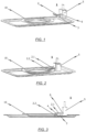
- the gripper system of the loading arrangement has a parallel gripper 1, wherein at least one clamping jaw 2, 3 of the parallel gripper 1 is designed as a segmented clamping jaw 2, which allows this clamping jaw 2 to be adapted at least in regions to a surface contour of a part of the washware 10, 11 to be gripped by the parallel gripper 1.
- the at least one segmented clamping jaw 2 of the parallel gripper 1 is divided into at least two and preferably more than two segments 2.1, 2.2 that are movable and in particular pivotable relative to one another, wherein each segment 2.1, 2.2 is connected to an adjacent segment 2.2, 2.1 via a joint region 4 and in particular a swivel joint region such that the segments 2.1, 2.2 of the segmented clamping jaw 2 are movable and in particular pivotable, in particular as required, in the direction of the gripping region and/or in the opposite direction.
- the embodiment of the parallel gripper 1 shown is characterized in that the parallel gripper 1 has a gripper housing 5 in in which, at least in some areas, a drive for at least one of the at least two clamping jaws 2, 3 of the parallel gripper 1 is accommodated or can be accommodated.
- the drive is assigned a slide element 6 which is movable and in particular displaceable relative to the gripper housing 5, wherein the segmented clamping jaw 2 is movable and in particular displaceable with the slide element 6 relative to the gripper housing 5.
- the other (non-segmented) clamping jaw 3 of the parallel gripper 1 is designed as a gripping finger which is rigidly connected to the gripper housing 5 of the parallel gripper 1.
- the realizable gripping range of the parallel gripper 1 can be varied.
- the clamping jaw that can be moved with the slide element 6 as a segmented clamping jaw 2
- this clamping jaw 2 it is possible for this clamping jaw 2 to be automatically or independently adaptable, at least in part, to a surface contour of a part of the washware 10, 11 gripped by the parallel gripper 1 in the gripped state.
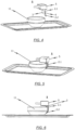
- the parallel gripper 1 is suitable for manipulating flat tableware items such as plates 10 or saucers (cf. FIG. 1 to FIG. 3 ), while by rotating the parallel gripper 1 by 90°, the edge of bowls 11, cups or other pots can also be gripped, as shown in FIG. 4 to FIG. 6 is indicated.
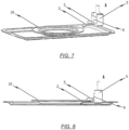
- the FIG. 7 to FIG. 10 The second embodiment shown is characterized in that the (non-segmented) gripping finger 3 of the parallel gripper 1 is movable and in particular displaceable with the slide element 6 relative to the gripper housing 5, while on the other hand the segmented clamping jaw 2 is rigidly connected to the gripper housing 5.
- FIG. 7 and FIG. 8 shown how in the second embodiment flat items of dishware, in particular plates 10, can be manipulated, while in FIG. 9 and FIG. 10 It is shown that with one and other types of wash items, in particular bowls 11, cups, etc., can also be manipulated using the same parallel gripper 1.
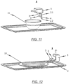
- FIG. 11 and FIG. 12 The further embodiment shown is characterized in that a total of two non-segmented clamping jaws 3 are provided, each in the form of a gripping finger, wherein these two gripping fingers are movable and in particular displaceable with the slide element 6 relative to the gripper housing 5.
- the two further clamping jaws 3 designed as gripping fingers are arranged next to one another on a line running perpendicular to the direction of movement of the slide element 6.
- corresponding rigid or flexible/segmented clamping jaws 2, 3 are arranged on opposite sides of the gripper housing 5 in order to be able to realize different gripping areas.
- the invention further relates to a conveyor dishwasher (not shown in the drawings) with at least one transport device, preferably in the form of at least one conveyor belt, wherein the conveyor dishwasher is provided with at least one loading area at its inlet area for the preferably automatic placement of items to be washed in the conveyor dishwasher's transport device.
- the loading system has at least one parallel gripper 1 of the type described above.
Landscapes
- Engineering & Computer Science (AREA)
- Robotics (AREA)
- Mechanical Engineering (AREA)
- Manipulator (AREA)
- Washing And Drying Of Tableware (AREA)
Applications Claiming Priority (1)
| Application Number | Priority Date | Filing Date | Title |
|---|---|---|---|
| DE102020114362.1A DE102020114362A1 (de) | 2020-05-28 | 2020-05-28 | System zum beladen einer spülmaschine, greifersystem für eine beladeanordnung zum beladen einer spülmaschine sowie spülmaschine |
Publications (2)
| Publication Number | Publication Date |
|---|---|
| EP3970592A1 EP3970592A1 (de) | 2022-03-23 |
| EP3970592B1 true EP3970592B1 (de) | 2024-08-14 |
Family
ID=75801489
Family Applications (1)
| Application Number | Title | Priority Date | Filing Date |
|---|---|---|---|
| EP21172049.5A Active EP3970592B1 (de) | 2020-05-28 | 2021-05-04 | System zum beladen einer spülmaschine, greifersystem für eine beladeanordnung zum beladen einer spülmaschine sowie spülmaschine |
Country Status (6)
| Country | Link |
|---|---|
| US (1) | US20210369077A1 (enExample) |
| EP (1) | EP3970592B1 (enExample) |
| JP (1) | JP2021186677A (enExample) |
| CN (1) | CN113729587A (enExample) |
| AU (1) | AU2021203145B2 (enExample) |
| DE (1) | DE102020114362A1 (enExample) |
Families Citing this family (3)
| Publication number | Priority date | Publication date | Assignee | Title |
|---|---|---|---|---|
| DE102020214301A1 (de) * | 2020-11-13 | 2022-05-19 | Robert Bosch Gesellschaft mit beschränkter Haftung | Vorrichtung und verfahren zum steuern eines roboters zum aufnehmen eines objekts in verschiedenen lagen |
| US12186784B2 (en) * | 2022-04-21 | 2025-01-07 | Skyworks Solutions, Inc. | Method of cleaning trays used for handling semiconductor packages |
| GB2622813A (en) * | 2022-09-28 | 2024-04-03 | Dyson Technology Ltd | Finger for a robotic gripper |
Family Cites Families (15)
| Publication number | Priority date | Publication date | Assignee | Title |
|---|---|---|---|---|
| DD248315A1 (de) | 1986-04-17 | 1987-08-05 | Univ Dresden Tech | Greiforgan mit in axialfuehrungen beweglichen stiften i |
| JPH06135549A (ja) * | 1992-10-26 | 1994-05-17 | Omron Corp | トレイ分離装置 |
| US6530996B2 (en) | 2000-07-13 | 2003-03-11 | Fuuga-Controls Oy | Method for washing items |
| JP4918004B2 (ja) * | 2006-11-24 | 2012-04-18 | パナソニック株式会社 | 多指ロボットハンド |
| WO2010029595A1 (ja) * | 2008-09-10 | 2010-03-18 | 株式会社ハーモニック・ドライブ・システムズ | ロボットハンドおよび板状物品のハンドリング方法 |
| NL2006950C2 (en) | 2011-06-16 | 2012-12-18 | Kampri Support B V | Cleaning of crockery. |
| CN103622655B (zh) * | 2013-12-20 | 2016-01-27 | 广东远东食品包装机械有限公司 | 洗碗机 |
| EP3191265A4 (en) * | 2014-09-12 | 2018-05-16 | Polyvalor, Limited Partnership | Mechanical finger for grasping apparatus |
| SG10201707766SA (en) * | 2017-09-20 | 2019-04-29 | Teoh Hwa Ang | Dish washing apparatus and dish drying apprartus |
| CN107584492B (zh) * | 2017-10-30 | 2023-12-22 | 安徽理工大学 | 铸造机器人用自适应气动抓手 |
| US10759062B2 (en) * | 2017-12-08 | 2020-09-01 | Dishcraft Robotics, Inc. | Article of dishware gripping systems |
| CN108095654A (zh) * | 2017-12-27 | 2018-06-01 | 重庆市臻憬科技开发有限公司 | 一种碗碟清洗机 |
| KR102600256B1 (ko) * | 2018-06-08 | 2023-11-08 | 피에이치디, 인크. | 자율적 캡슐화 그리퍼 툴링 |
| IT201900002695A1 (it) * | 2019-02-26 | 2020-08-26 | Ima Spa | Assieme di manipolazione robotizzato. |
| CN110802622A (zh) * | 2019-11-15 | 2020-02-18 | 北京邮电大学 | 一种可手内操作的手爪 |
-
2020
- 2020-05-28 DE DE102020114362.1A patent/DE102020114362A1/de active Pending
-
2021
- 2021-05-04 EP EP21172049.5A patent/EP3970592B1/de active Active
- 2021-05-17 AU AU2021203145A patent/AU2021203145B2/en not_active Ceased
- 2021-05-20 US US17/325,429 patent/US20210369077A1/en not_active Abandoned
- 2021-05-21 CN CN202110556068.8A patent/CN113729587A/zh active Pending
- 2021-05-26 JP JP2021088535A patent/JP2021186677A/ja active Pending
Also Published As
| Publication number | Publication date |
|---|---|
| AU2021203145B2 (en) | 2023-03-16 |
| CN113729587A (zh) | 2021-12-03 |
| US20210369077A1 (en) | 2021-12-02 |
| JP2021186677A (ja) | 2021-12-13 |
| EP3970592A1 (de) | 2022-03-23 |
| AU2021203145A1 (en) | 2021-12-16 |
| DE102020114362A1 (de) | 2021-12-02 |
Similar Documents
| Publication | Publication Date | Title |
|---|---|---|
| EP3970592B1 (de) | System zum beladen einer spülmaschine, greifersystem für eine beladeanordnung zum beladen einer spülmaschine sowie spülmaschine | |
| DE102010062457A1 (de) | Beladevorrichtung für eine Transportspülmaschine | |
| EP1436140A1 (de) | Verfahren und vorrichtung zum automatisierten handhaben von harzmatten bei der herstellung von smc-teilen | |
| EP2158833A2 (de) | Geschirrspülmaschine mit Handhabungsgerät an der Geschirraufgabe | |
| DE102019116461A1 (de) | Tauchglasieren von sanitärkeramik | |
| DE102021111279B4 (de) | Greifsystem und Verfahren zum Halten eines Werkstücks | |
| DE102019102800A1 (de) | System zum Beladen einer Spülmaschine und Spülmaschine mit einem derartigen System | |
| EP3840626B1 (de) | Reinigungssystem und verfahren zur reinigung von reinigungsgut | |
| EP0635340A1 (de) | Schneidautomat | |
| EP3906834B1 (de) | System zum beladen von unterschiedlichen transportspuren mindestens einer spülmaschine und spülmaschinenanordnung mit einem derartigen system | |
| DE102020104654A1 (de) | System zum beladen einer transportspülmaschine | |
| DE102020214604A1 (de) | Sortiersystem zum Sortieren von Besteckteilen | |
| EP3860419B1 (de) | Reinigungsvorrichtung und verfahren zur reinigung von reinigungsgut | |
| DE102019102813A1 (de) | Entladeanordnung zum Entladen von insbesondere auf Tabletts oder tablettartigen Gegenständen angeordneten Spülgutteilen | |
| EP3915456B1 (de) | System zum beladen mindestens einer transportspülmaschine mit spülgutteilen, anordnung aus mindestens einer transportspülmaschine und einem beladesystem sowie verfahren zum beladen mindestens einer transportspülmaschine mit spülgutteilen | |
| DE102008016410A1 (de) | Glasieranlage | |
| DE102020111231B3 (de) | Endeffektor mit Stabilisierungsbeinen für Kommissionierroboter, Kommissionierroboter mit einem solchen Endeffektor und Verfahren zum Steuern eins Kommissionierroboters | |
| DE102020214495B4 (de) | Geschirrstapler | |
| EP3368449B1 (de) | Transportband-material, transportband und vorrichtung mit einem transportband | |
| EP4596465A1 (de) | Beladesystem zum beladen einer transportspülmaschine mit spülgutteilen sowie anordnung zum zumindest teilautomatisierten reinigen von spülgutteilen mit einem beladesystem | |
| DE102023202231A1 (de) | Entnahmemodul und Verfahren zum Entnehmen von Spülgut | |
| DE102023106649A1 (de) | Entladesystem zum automatischen entladen von spülgut aus spülkörben oder transportbandfächern, spülmaschine mit einem solchen entladesystem sowie verfahren zum automatischen entladen von spülgut aus spülkörben oder transportbandfächern | |
| CH686572A5 (de) | Verfahren zur Herstellung von Glasscheiben und Vorrichtungen zur Durchfuhrung desselben. | |
| WO2024256610A1 (de) | Reinigungsvorrichtung und verfahren zur reinigung von reinigungsgut | |
| DE4042231A1 (de) | Greif- oder spannvorrichtung |
Legal Events
| Date | Code | Title | Description |
|---|---|---|---|
| PUAI | Public reference made under article 153(3) epc to a published international application that has entered the european phase |
Free format text: ORIGINAL CODE: 0009012 |
|
| STAA | Information on the status of an ep patent application or granted ep patent |
Free format text: STATUS: REQUEST FOR EXAMINATION WAS MADE |
|
| 17P | Request for examination filed |
Effective date: 20210504 |
|
| AK | Designated contracting states |
Kind code of ref document: A1 Designated state(s): AL AT BE BG CH CY CZ DE DK EE ES FI FR GB GR HR HU IE IS IT LI LT LU LV MC MK MT NL NO PL PT RO RS SE SI SK SM TR |
|
| GRAP | Despatch of communication of intention to grant a patent |
Free format text: ORIGINAL CODE: EPIDOSNIGR1 |
|
| STAA | Information on the status of an ep patent application or granted ep patent |
Free format text: STATUS: GRANT OF PATENT IS INTENDED |
|
| RIC1 | Information provided on ipc code assigned before grant |
Ipc: B25J 15/12 20060101ALI20240424BHEP Ipc: B25J 15/02 20060101ALI20240424BHEP Ipc: B25J 15/00 20060101ALI20240424BHEP Ipc: A47L 15/00 20060101ALI20240424BHEP Ipc: B25J 11/00 20060101ALI20240424BHEP Ipc: A47L 15/24 20060101AFI20240424BHEP |
|
| INTG | Intention to grant announced |
Effective date: 20240516 |
|
| GRAS | Grant fee paid |
Free format text: ORIGINAL CODE: EPIDOSNIGR3 |
|
| GRAA | (expected) grant |
Free format text: ORIGINAL CODE: 0009210 |
|
| STAA | Information on the status of an ep patent application or granted ep patent |
Free format text: STATUS: THE PATENT HAS BEEN GRANTED |
|
| AK | Designated contracting states |
Kind code of ref document: B1 Designated state(s): AL AT BE BG CH CY CZ DE DK EE ES FI FR GB GR HR HU IE IS IT LI LT LU LV MC MK MT NL NO PL PT RO RS SE SI SK SM TR |
|
| REG | Reference to a national code |
Ref country code: GB Ref legal event code: FG4D Free format text: NOT ENGLISH |
|
| REG | Reference to a national code |
Ref country code: CH Ref legal event code: EP |
|
| P01 | Opt-out of the competence of the unified patent court (upc) registered |
Free format text: CASE NUMBER: APP_41377/2024 Effective date: 20240712 |
|
| REG | Reference to a national code |
Ref country code: DE Ref legal event code: R096 Ref document number: 502021004761 Country of ref document: DE |
|
| REG | Reference to a national code |
Ref country code: IE Ref legal event code: FG4D Free format text: LANGUAGE OF EP DOCUMENT: GERMAN |
|
| REG | Reference to a national code |
Ref country code: LT Ref legal event code: MG9D |
|
| REG | Reference to a national code |
Ref country code: NL Ref legal event code: MP Effective date: 20240814 |
|
| PG25 | Lapsed in a contracting state [announced via postgrant information from national office to epo] |
Ref country code: NO Free format text: LAPSE BECAUSE OF FAILURE TO SUBMIT A TRANSLATION OF THE DESCRIPTION OR TO PAY THE FEE WITHIN THE PRESCRIBED TIME-LIMIT Effective date: 20241114 |
|
| PG25 | Lapsed in a contracting state [announced via postgrant information from national office to epo] |
Ref country code: NL Free format text: LAPSE BECAUSE OF FAILURE TO SUBMIT A TRANSLATION OF THE DESCRIPTION OR TO PAY THE FEE WITHIN THE PRESCRIBED TIME-LIMIT Effective date: 20240814 Ref country code: PL Free format text: LAPSE BECAUSE OF FAILURE TO SUBMIT A TRANSLATION OF THE DESCRIPTION OR TO PAY THE FEE WITHIN THE PRESCRIBED TIME-LIMIT Effective date: 20240814 Ref country code: GR Free format text: LAPSE BECAUSE OF FAILURE TO SUBMIT A TRANSLATION OF THE DESCRIPTION OR TO PAY THE FEE WITHIN THE PRESCRIBED TIME-LIMIT Effective date: 20241115 Ref country code: PT Free format text: LAPSE BECAUSE OF FAILURE TO SUBMIT A TRANSLATION OF THE DESCRIPTION OR TO PAY THE FEE WITHIN THE PRESCRIBED TIME-LIMIT Effective date: 20241216 Ref country code: FI Free format text: LAPSE BECAUSE OF FAILURE TO SUBMIT A TRANSLATION OF THE DESCRIPTION OR TO PAY THE FEE WITHIN THE PRESCRIBED TIME-LIMIT Effective date: 20240814 |
|
| PG25 | Lapsed in a contracting state [announced via postgrant information from national office to epo] |
Ref country code: BG Free format text: LAPSE BECAUSE OF FAILURE TO SUBMIT A TRANSLATION OF THE DESCRIPTION OR TO PAY THE FEE WITHIN THE PRESCRIBED TIME-LIMIT Effective date: 20240814 |
|
| PG25 | Lapsed in a contracting state [announced via postgrant information from national office to epo] |
Ref country code: LV Free format text: LAPSE BECAUSE OF FAILURE TO SUBMIT A TRANSLATION OF THE DESCRIPTION OR TO PAY THE FEE WITHIN THE PRESCRIBED TIME-LIMIT Effective date: 20240814 |
|
| PG25 | Lapsed in a contracting state [announced via postgrant information from national office to epo] |
Ref country code: IS Free format text: LAPSE BECAUSE OF FAILURE TO SUBMIT A TRANSLATION OF THE DESCRIPTION OR TO PAY THE FEE WITHIN THE PRESCRIBED TIME-LIMIT Effective date: 20241214 |
|
| PG25 | Lapsed in a contracting state [announced via postgrant information from national office to epo] |
Ref country code: HR Free format text: LAPSE BECAUSE OF FAILURE TO SUBMIT A TRANSLATION OF THE DESCRIPTION OR TO PAY THE FEE WITHIN THE PRESCRIBED TIME-LIMIT Effective date: 20240814 |
|
| PG25 | Lapsed in a contracting state [announced via postgrant information from national office to epo] |
Ref country code: ES Free format text: LAPSE BECAUSE OF FAILURE TO SUBMIT A TRANSLATION OF THE DESCRIPTION OR TO PAY THE FEE WITHIN THE PRESCRIBED TIME-LIMIT Effective date: 20240814 Ref country code: RS Free format text: LAPSE BECAUSE OF FAILURE TO SUBMIT A TRANSLATION OF THE DESCRIPTION OR TO PAY THE FEE WITHIN THE PRESCRIBED TIME-LIMIT Effective date: 20241114 |
|
| PG25 | Lapsed in a contracting state [announced via postgrant information from national office to epo] |
Ref country code: RS Free format text: LAPSE BECAUSE OF FAILURE TO SUBMIT A TRANSLATION OF THE DESCRIPTION OR TO PAY THE FEE WITHIN THE PRESCRIBED TIME-LIMIT Effective date: 20241114 Ref country code: PT Free format text: LAPSE BECAUSE OF FAILURE TO SUBMIT A TRANSLATION OF THE DESCRIPTION OR TO PAY THE FEE WITHIN THE PRESCRIBED TIME-LIMIT Effective date: 20241216 Ref country code: PL Free format text: LAPSE BECAUSE OF FAILURE TO SUBMIT A TRANSLATION OF THE DESCRIPTION OR TO PAY THE FEE WITHIN THE PRESCRIBED TIME-LIMIT Effective date: 20240814 Ref country code: NO Free format text: LAPSE BECAUSE OF FAILURE TO SUBMIT A TRANSLATION OF THE DESCRIPTION OR TO PAY THE FEE WITHIN THE PRESCRIBED TIME-LIMIT Effective date: 20241114 Ref country code: NL Free format text: LAPSE BECAUSE OF FAILURE TO SUBMIT A TRANSLATION OF THE DESCRIPTION OR TO PAY THE FEE WITHIN THE PRESCRIBED TIME-LIMIT Effective date: 20240814 Ref country code: LV Free format text: LAPSE BECAUSE OF FAILURE TO SUBMIT A TRANSLATION OF THE DESCRIPTION OR TO PAY THE FEE WITHIN THE PRESCRIBED TIME-LIMIT Effective date: 20240814 Ref country code: IS Free format text: LAPSE BECAUSE OF FAILURE TO SUBMIT A TRANSLATION OF THE DESCRIPTION OR TO PAY THE FEE WITHIN THE PRESCRIBED TIME-LIMIT Effective date: 20241214 Ref country code: HR Free format text: LAPSE BECAUSE OF FAILURE TO SUBMIT A TRANSLATION OF THE DESCRIPTION OR TO PAY THE FEE WITHIN THE PRESCRIBED TIME-LIMIT Effective date: 20240814 Ref country code: GR Free format text: LAPSE BECAUSE OF FAILURE TO SUBMIT A TRANSLATION OF THE DESCRIPTION OR TO PAY THE FEE WITHIN THE PRESCRIBED TIME-LIMIT Effective date: 20241115 Ref country code: FI Free format text: LAPSE BECAUSE OF FAILURE TO SUBMIT A TRANSLATION OF THE DESCRIPTION OR TO PAY THE FEE WITHIN THE PRESCRIBED TIME-LIMIT Effective date: 20240814 Ref country code: ES Free format text: LAPSE BECAUSE OF FAILURE TO SUBMIT A TRANSLATION OF THE DESCRIPTION OR TO PAY THE FEE WITHIN THE PRESCRIBED TIME-LIMIT Effective date: 20240814 Ref country code: BG Free format text: LAPSE BECAUSE OF FAILURE TO SUBMIT A TRANSLATION OF THE DESCRIPTION OR TO PAY THE FEE WITHIN THE PRESCRIBED TIME-LIMIT Effective date: 20240814 |
|
| PG25 | Lapsed in a contracting state [announced via postgrant information from national office to epo] |
Ref country code: SM Free format text: LAPSE BECAUSE OF FAILURE TO SUBMIT A TRANSLATION OF THE DESCRIPTION OR TO PAY THE FEE WITHIN THE PRESCRIBED TIME-LIMIT Effective date: 20240814 Ref country code: RO Free format text: LAPSE BECAUSE OF FAILURE TO SUBMIT A TRANSLATION OF THE DESCRIPTION OR TO PAY THE FEE WITHIN THE PRESCRIBED TIME-LIMIT Effective date: 20240814 Ref country code: DK Free format text: LAPSE BECAUSE OF FAILURE TO SUBMIT A TRANSLATION OF THE DESCRIPTION OR TO PAY THE FEE WITHIN THE PRESCRIBED TIME-LIMIT Effective date: 20240814 |
|
| PG25 | Lapsed in a contracting state [announced via postgrant information from national office to epo] |
Ref country code: EE Free format text: LAPSE BECAUSE OF FAILURE TO SUBMIT A TRANSLATION OF THE DESCRIPTION OR TO PAY THE FEE WITHIN THE PRESCRIBED TIME-LIMIT Effective date: 20240814 |
|
| PG25 | Lapsed in a contracting state [announced via postgrant information from national office to epo] |
Ref country code: CZ Free format text: LAPSE BECAUSE OF FAILURE TO SUBMIT A TRANSLATION OF THE DESCRIPTION OR TO PAY THE FEE WITHIN THE PRESCRIBED TIME-LIMIT Effective date: 20240814 |
|
| PG25 | Lapsed in a contracting state [announced via postgrant information from national office to epo] |
Ref country code: SK Free format text: LAPSE BECAUSE OF FAILURE TO SUBMIT A TRANSLATION OF THE DESCRIPTION OR TO PAY THE FEE WITHIN THE PRESCRIBED TIME-LIMIT Effective date: 20240814 |
|
| REG | Reference to a national code |
Ref country code: DE Ref legal event code: R097 Ref document number: 502021004761 Country of ref document: DE |
|
| PLBE | No opposition filed within time limit |
Free format text: ORIGINAL CODE: 0009261 |
|
| STAA | Information on the status of an ep patent application or granted ep patent |
Free format text: STATUS: NO OPPOSITION FILED WITHIN TIME LIMIT |
|
| PGFP | Annual fee paid to national office [announced via postgrant information from national office to epo] |
Ref country code: DE Payment date: 20250529 Year of fee payment: 5 |
|
| PGFP | Annual fee paid to national office [announced via postgrant information from national office to epo] |
Ref country code: IT Payment date: 20250521 Year of fee payment: 5 |
|
| PGFP | Annual fee paid to national office [announced via postgrant information from national office to epo] |
Ref country code: FR Payment date: 20250526 Year of fee payment: 5 |
|
| 26N | No opposition filed |
Effective date: 20250515 |
|
| PGFP | Annual fee paid to national office [announced via postgrant information from national office to epo] |
Ref country code: AT Payment date: 20250721 Year of fee payment: 5 |
|
| PG25 | Lapsed in a contracting state [announced via postgrant information from national office to epo] |
Ref country code: SE Free format text: LAPSE BECAUSE OF FAILURE TO SUBMIT A TRANSLATION OF THE DESCRIPTION OR TO PAY THE FEE WITHIN THE PRESCRIBED TIME-LIMIT Effective date: 20240814 |
|
| REG | Reference to a national code |
Ref country code: CH Ref legal event code: H13 Free format text: ST27 STATUS EVENT CODE: U-0-0-H10-H13 (AS PROVIDED BY THE NATIONAL OFFICE) Effective date: 20251223 |
|
| PG25 | Lapsed in a contracting state [announced via postgrant information from national office to epo] |
Ref country code: LU Free format text: LAPSE BECAUSE OF NON-PAYMENT OF DUE FEES Effective date: 20250504 |
|
| PG25 | Lapsed in a contracting state [announced via postgrant information from national office to epo] |
Ref country code: CH Free format text: LAPSE BECAUSE OF NON-PAYMENT OF DUE FEES Effective date: 20250531 |
|
| GBPC | Gb: european patent ceased through non-payment of renewal fee |
Effective date: 20250504 |
|
| REG | Reference to a national code |
Ref country code: BE Ref legal event code: MM Effective date: 20250531 |
|
| PG25 | Lapsed in a contracting state [announced via postgrant information from national office to epo] |
Ref country code: MC Free format text: LAPSE BECAUSE OF FAILURE TO SUBMIT A TRANSLATION OF THE DESCRIPTION OR TO PAY THE FEE WITHIN THE PRESCRIBED TIME-LIMIT Effective date: 20240814 |
|
| PG25 | Lapsed in a contracting state [announced via postgrant information from national office to epo] |
Ref country code: GB Free format text: LAPSE BECAUSE OF NON-PAYMENT OF DUE FEES Effective date: 20250504 |
|
| PG25 | Lapsed in a contracting state [announced via postgrant information from national office to epo] |
Ref country code: IE Free format text: LAPSE BECAUSE OF NON-PAYMENT OF DUE FEES Effective date: 20250504 |
|
| PG25 | Lapsed in a contracting state [announced via postgrant information from national office to epo] |
Ref country code: BE Free format text: LAPSE BECAUSE OF NON-PAYMENT OF DUE FEES Effective date: 20250531 |