EP3968351A1 - Elektromagnetisches relais - Google Patents
Elektromagnetisches relais Download PDFInfo
- Publication number
- EP3968351A1 EP3968351A1 EP21196704.7A EP21196704A EP3968351A1 EP 3968351 A1 EP3968351 A1 EP 3968351A1 EP 21196704 A EP21196704 A EP 21196704A EP 3968351 A1 EP3968351 A1 EP 3968351A1
- Authority
- EP
- European Patent Office
- Prior art keywords
- spring
- movable spring
- armature
- base
- movable
- Prior art date
- Legal status (The legal status is an assumption and is not a legal conclusion. Google has not performed a legal analysis and makes no representation as to the accuracy of the status listed.)
- Pending
Links
- XEEYBQQBJWHFJM-UHFFFAOYSA-N Iron Chemical group [Fe] XEEYBQQBJWHFJM-UHFFFAOYSA-N 0.000 claims abstract description 40
- 238000006243 chemical reaction Methods 0.000 claims description 34
- 238000003780 insertion Methods 0.000 claims description 14
- 230000037431 insertion Effects 0.000 claims description 14
- 238000005192 partition Methods 0.000 claims description 14
- 238000010586 diagram Methods 0.000 description 11
- 230000003014 reinforcing effect Effects 0.000 description 10
- 238000005452 bending Methods 0.000 description 6
- 230000000903 blocking effect Effects 0.000 description 4
- 230000009286 beneficial effect Effects 0.000 description 3
- 238000000034 method Methods 0.000 description 3
- 235000003332 Ilex aquifolium Nutrition 0.000 description 2
- 241000209027 Ilex aquifolium Species 0.000 description 2
- 238000009434 installation Methods 0.000 description 2
- 238000004891 communication Methods 0.000 description 1
- 230000006835 compression Effects 0.000 description 1
- 238000007906 compression Methods 0.000 description 1
- 230000000694 effects Effects 0.000 description 1
- 230000005489 elastic deformation Effects 0.000 description 1
- 230000005611 electricity Effects 0.000 description 1
- 238000009413 insulation Methods 0.000 description 1
- 238000002955 isolation Methods 0.000 description 1
- 239000000463 material Substances 0.000 description 1
- 238000012986 modification Methods 0.000 description 1
- 230000004048 modification Effects 0.000 description 1
- 238000012544 monitoring process Methods 0.000 description 1
- 230000001846 repelling effect Effects 0.000 description 1
- 238000000926 separation method Methods 0.000 description 1
Images


Classifications
-
- H—ELECTRICITY
- H01—ELECTRIC ELEMENTS
- H01H—ELECTRIC SWITCHES; RELAYS; SELECTORS; EMERGENCY PROTECTIVE DEVICES
- H01H50/00—Details of electromagnetic relays
- H01H50/54—Contact arrangements
- H01H50/56—Contact spring sets
-
- H—ELECTRICITY
- H01—ELECTRIC ELEMENTS
- H01H—ELECTRIC SWITCHES; RELAYS; SELECTORS; EMERGENCY PROTECTIVE DEVICES
- H01H1/00—Contacts
- H01H1/50—Means for increasing contact pressure, preventing vibration of contacts, holding contacts together after engagement, or biasing contacts to the open position
- H01H1/54—Means for increasing contact pressure, preventing vibration of contacts, holding contacts together after engagement, or biasing contacts to the open position by magnetic force
-
- H—ELECTRICITY
- H01—ELECTRIC ELEMENTS
- H01H—ELECTRIC SWITCHES; RELAYS; SELECTORS; EMERGENCY PROTECTIVE DEVICES
- H01H50/00—Details of electromagnetic relays
- H01H50/64—Driving arrangements between movable part of magnetic circuit and contact
- H01H50/641—Driving arrangements between movable part of magnetic circuit and contact intermediate part performing a rectilinear movement
- H01H50/642—Driving arrangements between movable part of magnetic circuit and contact intermediate part performing a rectilinear movement intermediate part being generally a slide plate, e.g. a card
-
- H—ELECTRICITY
- H01—ELECTRIC ELEMENTS
- H01H—ELECTRIC SWITCHES; RELAYS; SELECTORS; EMERGENCY PROTECTIVE DEVICES
- H01H51/00—Electromagnetic relays
- H01H51/22—Polarised relays
- H01H51/2272—Polarised relays comprising rockable armature, rocking movement around central axis parallel to the main plane of the armature
-
- H—ELECTRICITY
- H01—ELECTRIC ELEMENTS
- H01H—ELECTRIC SWITCHES; RELAYS; SELECTORS; EMERGENCY PROTECTIVE DEVICES
- H01H1/00—Contacts
- H01H1/12—Contacts characterised by the manner in which co-operating contacts engage
- H01H1/14—Contacts characterised by the manner in which co-operating contacts engage by abutting
- H01H1/24—Contacts characterised by the manner in which co-operating contacts engage by abutting with resilient mounting
- H01H1/26—Contacts characterised by the manner in which co-operating contacts engage by abutting with resilient mounting with spring blade support
- H01H1/28—Assembly of three or more contact-supporting spring blades
Definitions
- the present disclosure relates to the technical field of an electromagnetic relay, and in particular, to an electromagnetic relay that can be applied to three-phase alternating current.
- Electromagnetic relay is a kind of relay that uses electromagnetic force to drive relative movement of mechanical parts to produce a predetermined response. It is generally composed of a magnetic circuit part, a movable spring part, a stationary spring part, a base and a case.
- the magnetic circuit part includes an iron core, a bobbin wound with an enameled wire, an armature, a yoke, etc.
- Electromagnetic relays of related art are generally suitable for single-phase circuits, and only a few electromagnetic relays are suitable for three-phase alternating current. However, some of these electromagnetic relays do not have the function of monostable state, and some do not have the function of forced guidance.
- an electromagnetic relay includes a base and a magnetic circuit part, the magnetic circuit part includes a bobbin equipped with an iron core and an enameled wire, an armature and a yoke connected to the iron core, the bobbin is disposed horizontally on the base, the armature is disposed at a knife edge of the yoke and is cooperated with a pole surface of the iron core, the electromagnetic relay further includes at least three groups of contact units distributed side by side, each group of contact units respectively includes a movable spring part and a stationary spring part, the movable spring part and the stationary spring part are respectively arranged on the base and cooperate with each other correspondingly, the armature is connected to the movable spring part of each of the contact units through the pushing card to drive the movable spring part to move.
- the magnetic circuit part and each of the contact units are located in different cavities of the base.
- the lead-out terminal of the movable spring part and the lead-out terminal of the stationary spring part are located at opposite ends of the base.
- one end of the pushing card is provided with an insulating connector
- the connector is provided with an insertion slot
- one end of the armature away from the pole surface of the iron core is inserted into the insertion slot and is enclosed by the insertion slot.
- a part where the armature cooperates with the pole surface of the iron core is bent toward a side away from the iron core to form an oblique shape.
- the movable spring part is configured to be a structure capable of resisting short-circuit current
- the movable spring part comprises a movable spring lead-out sheet, a rigid spring and a flexible connector
- the movable spring lead-out sheet is inserted into the base, and a bottom of the movable spring lead-out sheet forms a lead-out terminal of the movable spring part
- a top of the rigid spring is rotatably connected with the movable spring lead-out sheet, so that the rigid spring is capable of rotating in a direction away from or close to the movable spring lead-out sheet
- a flexible connector is further connected between the top of the rigid spring and a top of the movable spring lead-out sheet
- a movable contact is provided at a bottom of the rigid spring on the side opposite to the movable spring lead-out sheet
- the pushing card is provided with a plurality of slots at intervals along a length direction of the base, and the plurality of slots correspond to the at least three groups of mov
- the movable spring part 3 further comprises a reaction force spring, the reaction force spring is located between the movable spring lead-out sheet and the rigid spring, and a bottom of the reaction force spring is fixedly connected to the rigid spring, there is a predetermined distance between a top of the reaction force spring and the rigid spring, and the top of the reaction force spring is clamped in the slot.
- the pushing card is provided with a limiting member at one end facing the armature, and the limiting member cooperates with a first partition wall provided on the base to resist a pushing stroke of the pushing card, the first partition wall is located between the armature and the contact unit adjacent to the armature; an end of the pushing card away from the armature cooperates with the movable spring lead-out sheet furthest away from the armature to limit the reset stroke of the pushing card.
- the electromagnetic relay further includes an auxiliary movable spring provided with an auxiliary movable contact and an auxiliary stationary spring provided with an auxiliary stationary contact, the auxiliary movable spring and the auxiliary stationary spring are respectively inserted into the base and located on a side of the base where the armature is located; the pushing card or the armature is provided with a driving part cooperating with the auxiliary movable spring to drive the auxiliary movable spring to move; an action state of the auxiliary movable spring is opposite to an action state of the movable spring part.
- a return spring is inserted between the yoke and the base, the return spring restricts the armature and provides the armature to reset;
- the bobbin is located in a length direction of the base, and the at least three groups of contact units are distributed along the length direction of the base, and the movable spring part of each of the contact units are respectively vertical, and are distributed along a width direction of the base with the bobbin, the pushing card is located in the length direction of the base, the pushing card is limited in an up and down direction by a second partition wall provided on the base between adjacent contact units.
- the present disclosure has the following beneficial effects:
- an electromagnetic relay includes a body, a magnetic circuit part, a contact part, and a pushing card, the magnetic circuit part, the contact part, and the pushing card are respectively installed in the body, the armature of the magnetic circuit part cooperates with a movable spring part of the contact part in linkage through the pushing card; the pushing card is located between the movable spring part and an inner side surface of the body, the pushing card includes a pushing rod that cooperates with the movable spring part and a pushing block that is disposed at one end of the pushing rod and cooperates with the armature, the pushing block is located in the extending direction of the length of the pushing rod.
- the body is further provided with a limiting structure which limits the movement of the pushing card toward the inner side surface.
- the body includes a case and a base, and the base serves as a carrier for the magnetic circuit part and the contact part, the case is connected to the base and contains the magnetic circuit part, the contact part and the pushing card, and the inner side surface is provided on the case; the limiting structure is provided on the base.
- the limiting structure includes at least two limiting components, and each of the limiting components is respectively mounted on the base and limits and protects the pushing card;
- the base is provided with a retaining wall located between the movable spring part and the magnetic circuit part, each of the limiting components is respectively mounted on the retaining wall, and each of the limiting components is partially blocked on a side of the pushing card close to the inner side surface.
- the retaining wall is provided with a plurality of mounting portions, and at least one end of each of the limiting components is respectively interference-fitted and inserted into a socket provided in the corresponding mounting portion; the limiting component is U-shaped.
- the pushing rod is provided with a first slot for snap-fitting with the movable spring part
- the pushing block is provided with a second slot for snap-fitting with the armature, the notch of the first slot and the notch of the second slot are respectively located on a side of the pushing card facing away from the inner side surface.
- the pushing rod is provided with at least one group of reinforcing structure
- the reinforcing structure includes a plurality of reinforcing ribs spaced apart along a length direction of the pushing rod, and each of the reinforcing ribs is located at a width direction of the pushing rod, respectively.
- the movable spring part is provided with a limiting groove for restricting the up and down movement of the pushing card, the limiting groove is respectively penetrated at both ends in the length direction of the pushing rod, and the pushing card is clamped in the limiting groove.
- the second slot two opposite sides of the second slot are respectively provided with a first limiting rib and a second limiting rib which are extend in a vertical direction, the surfaces of the first limiting rib and the second limiting rib are arc-shaped, a portion of the armature located in the second slot fits between the first limiting rib and the second limiting rib on two sides of the second slot; there are a plurality of first slots, and the plurality of the first slots are distributed along the length direction of the pushing rod;
- the movable spring part includes a movable spring lead-out sheet, a rigid spring and a reaction force spring, the movable spring lead-out sheet is mounted on the body, an upper end of the rigid spring is rotatably connected with an upper end of the movable spring lead-out sheet, a movable contact is provided at a lower end of the rigid spring, and a lower end of the reaction force spring is fixed on a side of the rigid spring facing away from the movable contact, and there is a gap between the
- the magnetic circuit part includes an armature, a coil assembly and a yoke connected to the coil assembly, the coil assembly is lying in the body and is arranged side by side with the movable spring part, the armature is movably arranged at a knife edge of the yoke and is fitly installed outside one end of the coil assembly in an axial direction of the coil assembly, and one end of the armature facing an inner side surface is connected to the pushing card 5; there are a plurality of movable spring parts, and the plurality of movable spring parts are distributed at intervals along the length direction of the pushing card.
- the present disclosure has the following beneficial effects:
- an electromagnetic relay applicable to three-phase alternating current of the present disclosure is not limited to the embodiments.
- an electromagnetic relay which can be applied to three-phase alternating current.
- an electromagnetic relay applicable to three-phase alternating current of the present disclosure includes a base 1, a magnetic circuit part 2, and a housing (not shown in the figure), the magnetic circuit part 2 includes a bobbin 21 equipped with an iron core 25 and an enameled wire 24, an armature 23, and a yoke 22 connected to the iron core 25, the bobbin 21 is disposed horizontally on the base 1 and extends along the length direction X of the base 1, the armature 23 is arranged at the knife edge of the yoke 22 and is cooperated with the pole surface 251 of the iron core 25.
- the yoke 22 is L-shaped and includes a first yoke portion 221 and a second yoke portion 222.
- the first yoke portion 221 is perpendicular to the second yoke portion 222, the first yoke portion 221 is fixedly connected to the end of the iron core 25 away from the armature 23 (or, it can also be integrally formed), and the second yoke portion 222 is fitted on the side of the bobbin 21.
- the electromagnetic relay of the present disclosure also includes at least three groups of contact units distributed side by side, each group of contact units respectively includes a movable spring part 3 and a stationary spring part 4, and the movable spring part 3 and the stationary spring part 4 are respectively arranged on the base 1 and cooperate with each other correspondingly; the armature 23 is connected to the movable spring part 3 of each contact unit through the pushing card 5 to drive the movable spring part 3 to move.
- the bobbin 21 is specifically located on the base 1 and distributed along the length direction X of the base 1, and the at least three groups of contact units are distributed along the length direction X of the base 1, and the movable spring part 3 of each contact unit is respectively vertical, and are distributed along the width direction Y of the base 1 with the bobbin 21, and the pushing card 5 is arranged along the length direction X of the base 1.
- the number of the contact units is specifically four groups, but is not limited to this.
- the housing connects with the base 1, and the magnetic circuit part 2 and the contact units are contained in the housing cavity.
- the magnetic circuit part 2 and each of the contact units are respectively located in different cavities of the base 1.
- the lead-out terminal 311 of the movable spring part 3 and the lead-out terminal 411 of the stationary spring part 4 are located on opposite sides of the base 1.
- the lead-out terminal 311 of the movable spring part 3 and the lead-out terminal 411 of the stationary spring part 4 are located on opposite sides of the base 1 in the width direction Y, in this way, it can be avoided that the lead-out terminals 311 of the movable spring parts 3 and the lead-out terminals 411 of the stationary spring parts 4 are located at the same side, resulting in congested space, inconvenient wiring and prone to short circuits.
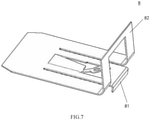
- the end of the pushing card 5 close to the armature 23 is integrally formed with an insulating connector 51, as shown in FIG. 6 , the connector 51 is provided with an insertion slot 511, and the end of the armature 23 away from the pole surface 251 of the iron core 25 is inserted into the insertion slot 511 and is enclosed by the insertion slot 511.
- the insertion slot 511 is U-shaped with at least one end closed, and two opposite slot walls are respectively provided with convex ribs 512, and the surface of each of the convex ribs 512 is arc-shaped. The end of the armature 23 away from the iron core 25 is inserted into the insertion slot 511 to achieve transitional fit with the rib 512, thereby restricting the end of the armature 23 away from the iron core 25 from coming out.
- the armature 23 is roughly in a shape of a section of a line, and the part where the armature 23 cooperates with the pole surface 251 of the iron core 25 is bent toward a side away from the iron core 25 to form an oblique shape, as shown in FIG. 4 . So that the angle of rotation of the armature 23 is greater, so that the stroke of the pushing card 5 is greater. Therefore, the contact gap between the movable spring part 3 and the stationary spring part 4 in the open state is larger, so that the safety performance of the electromagnetic relay of the present disclosure in the open state can be improved.
- the movable spring part 3 is designed to be a structure capable of resisting short-circuit current, and includes a movable spring lead-out sheet 31 and a movable spring, the movable spring lead-out sheet 31 is inserted into the base 1 and the bottom thereof forms a lead-out terminal 311 of the movable spring part 3, the top of the movable spring is connected with the top of the movable spring lead-out sheet 31, and a movable contact 33 is provided at the bottom of the movable spring at the side facing away from the movable spring lead-out sheet 31.
- the movable spring is specifically a rigid spring 32 as shown in FIG. 1 , but is not limited to this. In other embodiments, the movable spring may also be a resilient spring, the top of the movable spring is fixedly connected to the top of the movable spring lead-out sheet.
- the movable spring is used as the rigid spring 32 for description.
- the top of the rigid spring 32 is rotatably connected with the top of the movable spring lead-out sheet 31 so that the rigid spring 32 can rotate in a direction away from or close to the movable spring lead-out sheet 31.
- the top of the rigid spring 32 and the top of the movable spring lead-out sheet 31 are connected by a rotating shaft 35, and a flexible connector 36 is further connected between the top of the rigid spring 32 and the top of the movable spring lead-out sheet 31.
- the pushing card 5 is provided with a plurality of slots 54 at intervals along its length direction, and the plurality of slots 54 correspond to the at least three groups of the movable spring parts 3 in a one-to-one correspondence, the movable spring (i.e., the rigid springs 32) of the movable spring parts 3 are respectively clamped in the corresponding slots 54.
- the movable spring part 3 further includes a reaction force spring 34, the reaction force spring 34 is located between the movable spring lead-out sheet 31 and the rigid spring 32, and the bottom of the reaction force spring 34 is fixedly connected to the rigid spring 32, there is a predetermined distance between the top of the reaction force spring 34 and the rigid spring 32, and the top of the reaction force spring 34 is clamped in the slot 54.
- the reaction force spring 34 is pushed to push the rigid spring 32 to move in the direction close to the stationary spring part 4, thereby generating an overstroke.
- the bottom of the rigid spring 32 is bent into an oblique shape toward the side away from the stationary spring part 4, which is beneficial to further increase the contact gap between the movable spring part 3 and the stationary spring part 4 in the cut-off state.
- the movable spring lead-out sheet 31 of each movable spring part 3 are respectively provided with a relief groove for avoiding the pushing card 5.
- the pushing card 5 is provided with a limiting member 53 at one end facing the armature 23, and the limiting member 53 cooperates with the first partition wall 11 provided on the base 1 to resist the pushing stroke of the pushing card 5, the first partition wall 11 is located between the armature 23 and the contact unit adjacent to the armature 23.
- the end of the pushing card 5 away from the armature 23 cooperates with the movable spring lead-out sheet 31 furthest away from the armature 23 to limit the reset stroke of the pushing card 5.
- the pushing stroke refers to the stroke generated by the movement of the pushing card 5 driven by the armature 23 when the armature 23 is attracted to the pole surface 251
- the reset stroke refers to the stroke generated by the movement of the pushing card 5 driven by the armature 23 when the armature 23 is separated from the pole surface 251 of the iron core 25.
- the pushing card 5 When the limiting member 53 is in contact with the first partition wall 11, the pushing card 5 is pushed to the extreme position, when the end of the pushing card 5 away from the armature 23 is in contact with the movable spring lead-out sheet 31 furthest away from the armature 23, the pushing card 5 is reset to the extreme position.
- the pushing card 5 is limited in the up and down direction by the second partition wall 12 provided on the base 1 between the adjacent contact units.
- the second partition wall 12 is broken into upper and lower parts at the position of the pushing card 5, which is used to avoid the pushing card 5 and limit the pushing card 5 in the up and down direction, at the same time, the lower part of the second partition wall 12 can support the pushing card 5.
- the electromagnetic relay of the present disclosure further includes an auxiliary movable spring 6 provided with an auxiliary movable contact and an auxiliary stationary spring 7 provided with an auxiliary stationary contact, both them are respectively inserted into the base 1 and located on the side of the base 1 where the armature 23 is located;
- the pushing card 5 is provided with a driving part 52 which cooperates with the auxiliary movable spring 6 to drive the auxiliary movable spring 6 to move;
- the action state of the auxiliary movable spring 6 is opposite to the action state of the movable spring part 3.
- the auxiliary movable spring 6 moves in the direction of disconnecting from the auxiliary stationary spring 7 when the movable spring part 3 moves in the direction of disconnecting from the stationary spring part 4, the auxiliary movable spring 6 moves in the direction of attracting and engaging with the auxiliary stationary spring 7.
- the driving part 52 is specifically located at the bottom of the connector 51. In other embodiments, the driving part 52 is provided on the armature 23.
- a return spring 8 is inserted between the yoke 22 and the base 1, the return spring 8 restricts the armature 23 and can reset the armature 23. Specifically, as shown in FIGS. 1-2 and 8 , a return spring 8 is inserted between the yoke 22 and the base 1, the return spring 8 restricts the armature 23 and can reset the armature 23. Specifically, as shown in FIGS. 1-2 and 8 , a return spring 8 is inserted between the yoke 22 and the base 1, the return spring 8 restricts the armature 23 and can reset the armature 23. Specifically, as shown in FIGS.
- the armature 23 is provided with a through slot 231 between its rotation fulcrum 232 and its an end away from the iron core 25,
- the return spring 8 includes a first bending portion 81 and a second bending portion 82, the first bending portion 81 extends in a direction away from the pushing card 5, the first bending portion 81 passes through the through slot 231 and rests on the side of the armature 23 facing away from the iron core 25 (i.e., the outer side of the armature 23), so as to further limit the armature 23 and prevent the armature 23 from falling off.
- the second bending portion 82 of the return spring 8 extends in a direction close to the pushing card 5, the second bending portion 82 passes through the through slot 231 of the armature 23 and then rests on the side of the armature 23 facing away from the iron core 25 (i.e., the outer side of the armature 23) to provide the armature 23 for resetting.
- the stationary spring part 4 includes a stationary spring 41 and a stationary contact 42, the stationary spring 41 is inserted into the bottom of the base 1 from one side of the base 1 along the width direction Y of the base 1, and a stationary contact 42 is provided at one end of the stationary spring 41 facing the movable spring part 3, the end of the stationary spring away from the movable spring part 3 extends below the base 1 to form the lead-out terminal 411 of the stationary spring part 4.
- the movable spring lead-out sheet 31 is also inserted into the base 1 from the side of the base 1 along the width direction Y of the base 1.
- the electromagnetic relay of the present disclosure can be applied to a three-phase alternating current, and can be applied to a three-phase four-wire circuit, and each group of contact units can reach a current-carrying capacity of 40A, and can resist a short-circuit current of 3 kA.
- the armature 23 rotates around the knife edge of the yoke 22 (the knife edge is the notch at the end of the second yoke portion 222 away from the first yoke portion 221, and the notch is used to insert the armature 23), attracts and engages with the pole surface 251 of the iron core 25, and at the same time drives the pushing card 5 to move along the length direction X of the base 1, and drives the reaction force spring 34 and the rigid spring 32 of the movable spring part 3 to move to realize the movable contact 33 and the stationary contact 42 are in a close state.
- the reaction force spring 34 begins to be plastically deformed, after the armature 23 is in full contact with the pole surface 251 of the iron core 25, the deformation of the reaction force spring 34 ends, and the overstroke is mainly realized by the elastic deformation of the reaction force spring 34.
- the rigid spring 32 is only responsible for conducting electricity, and is not responsible for deforming to achieve the over-travel function.
- the armature 23 When the coil (i.e., the enameled wire 24) is de-energized, the armature 23 is reset under the action of the return spring 8, and at the same time drives the pushing card 5 to move in the opposite direction, and drives the reaction force spring 34 and the rigid spring 32 of each movable spring part 3 to move in the opposite direction, so that the movable contact 33 and the stationary contact 42 are in a cut-off state.
- the pushing card 5 cannot be reset, so that the movable contacts 33 of the remaining groups of the movable spring parts 3 cannot be disconnected from the corresponding stationary contacts, thereby achieving a forced guiding function.
- the disconnection between the auxiliary movable contact and the auxiliary stationary contact is realized by the driving part 52 of the pushing card 5 pushing the head of the auxiliary movable spring 6.
- the connection between the auxiliary movable contact and the auxiliary stationary contact is realized by the reaction force of the auxiliary movable spring 6.
- High insulation is achieved between the auxiliary contact part and the main contact part (namely contact unit).
- the auxiliary contact part can monitor the state of the main contact part, no matter which main contact is stuck, the auxiliary contact can't be closed, so as to realize the blocking function.
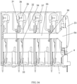
- An electromagnetic relay of the present disclosure includes a body, a magnetic circuit part, a contact part, and a pushing card 5.
- the body includes a case 9 and a base 1.
- the magnetic circuit part, the contact part, and the pushing card 5 are respectively installed in the body, and the contact part includes a movable spring part 3 and a stationary spring part 4, the armature 23 of the magnetic circuit part cooperates with the movable spring part 3 of the contact part in linkage through the pushing card 5. As shown in FIG.
- the pushing card 5 is arranged horizontally, and the pushing card 5 is located between the movable spring part 3 and an inner side surface 91 of the case 9.
- the pushing card 5 includes a pushing rod 55 that cooperates with the movable spring part 3 and a pushing block 56 that cooperates with the armature 23 and is disposed at one end of the pushing rod 55, the pushing block 56 is located in the extending direction of the length of the pushing rod 55.
- the body includes a case 9 and a base 1, and the base 1 serves as a carrier for the magnetic circuit part and the contact part, the case 9 is connected to the base 1 and contains the magnetic circuit part, the contact part and the pushing card 5, and the inner side surface 91 is provided on the case 9.
- the base 1 serves as a carrier for the magnetic circuit part and the contact part
- the case 9 is connected to the base 1 and contains the magnetic circuit part
- the contact part and the pushing card 5 and the inner side surface 91 is provided on the case 9.
- the magnetic circuit part specifically includes the armature 23, the coil assembly 20 and the yoke 22 connected to the coil assembly 20, the coil assembly 20 is lying on the base 1 and extends along the length direction X of the base 1, and is movably arranged at the knife edge of the yoke 22 with the armature 23, the armature 23 is fitly installed outside one end of the coil assembly 20 in the axial direction, and the end of the armature 23 facing the inner side surface is connected to the pushing card 5.
- the coil assembly 20 and the pushing card 5 are respectively located in the length direction X of the base 1, the coil assembly 20 and the movable spring part 3 are distributed along the width direction Y of the base 1.
- the coil assembly 20 specifically includes an iron core 25, an enameled wire 24, and a bobbin 21.
- the bobbin 21 is lying on the base 1.
- the iron core 25 is inserted into the bobbin 21 with its two ends exposed, and the enameled wire 24 is wound around the bobbin 21.
- the yoke 22 is L-shaped, and includes a first yoke portion 2212 and a second yoke portion 222, the first yoke portion 221 is perpendicular to the second yoke portion 222, the first yoke portion 221 is fixedly connected to the end of the iron core 25 away from the armature 23 (or, it can also be integrally formed), and the second yoke portion 222 is fitted on the side of the bobbin 21 close to the movable spring part 3; the armature 23 is specifically limited by a compression spring at the knife edge of the second yoke portion 222 of the yoke 22.
- the body is further provided with a limiting structure, which limits the movement of the pushing card toward the inner side surface 91.
- the limiting structure is specifically arranged on the base 1.
- the limiting structure specifically includes at least two limiting components 30, and each limiting component 30 is respectively mounted on the base 1 and limits and protects the pushing card 5.
- the number of the limiting component 30 is specifically two, but is not limited thereto. For example, it may also be three, four or more.
- the base 1 has a retaining wall 101 located between the movable spring part 3 and the magnetic circuit part, the limiting components 30 are respectively mounted on the retaining wall 101, and each of the limiting components 30 is partially blocked on the side of the pushing card 5 close to the inner side surface 91.
- the retaining wall 101 is provided with a plurality of column-shaped mounting portions 102, and at least one end of each limiting component 30 is respectively interference-fitted and inserted into the socket 103 provided in the corresponding mounting portion 102.
- the structure of the limiting component 30 is shown in FIG.
- the limiting component 30 is substantially U-shaped, and includes a blocking rod 301 and two inserting rods 302 arranged at both ends of the blocking rod 301, when the limiting component 30 is installed on the column-shaped mounting portion 102, the limiting component 30 is in the above-mentioned substantially U-shaped state rotated 90° clockwise, the blocking rod 301 is located in the vertical direction and is cooperated at the side of the pushing rod 55 facing the inner side surface 91, the two inserting rods 302 are respectively located above and below the pushing rod 55, and are respectively inserted into the sockets 103 provided in the corresponding mounting portion 102 in an interference manner.
- the limiting component is L-shaped or the like.
- the pushing rod 55 is provided with at least one group of reinforcing structure, the reinforcing structure includes a plurality of reinforcing ribs 552 spaced apart along the length direction of the pushing rod 55, and each reinforcing rib 552 is located at the width direction of the pushing rod 55, respectively.
- the pushing rod 55 includes two groups of reinforcing structures, one of which is located on the upper surface of the inner protrusion of the pushing rod 55, and the other is located on the lower surface of the inner protrusion of the pushing rod 55.
- the movable spring part 3 is provided with a limiting groove 37 for restricting the up and down movement of the pushing card 5, as shown in FIG. 16 , the limiting groove 37 penetrates in the length direction of the pushing card 5, and the pushing rod 55 of the pushing card 5 is partially clamped into the limiting groove 37.
- the side of the pushing rod 55 of the pushing card 5 facing the inner side surface 91 is flush with the side of the pushing block 56 facing the inner side surface 91, as shown in FIG. 14 .
- the pushing rod 55 is provided with a first slot 551 for snap-fitting with the movable spring part 3
- the pushing block 56 is provided with a second slot 561 for snap-fitting with the armature 23
- the notch of the first slot 551 and the notch of the second slot 561 are respectively located on the side of the pushing card 5 facing away from the inner side surface 91, as shown in FIGS. 14 and 15 .
- there is a plurality of movable spring parts 3 there is also a plurality of first slots 551, and the first slots 551 and the movable spring parts 3 are arranged in a one-to-one correspondence.
- the two opposite sides of the second slot 561 are respectively provided with a first limiting rib 562 and a second limiting rib 563 which are extend in the vertical direction, the surfaces of the first limiting rib 562 and the second limiting rib 563 are arc-shaped, the portion of the armature 23 located in the second slot 561 fits between the first limiting rib 562 and the second limiting rib 563 on the two sides of the second slot 561. So that the armature 23 is made to perform a tangential movement relative to the pushing card 5, and the movement is stable.
- the pushing rod 55 is provided with a partition 553 between the armature 23 and the movable spring part 3 close to the armature 23, so that the partition 553 can be used to increase the air gap and creepage distance between the contact part and the magnetic circuit part of the relay.
- the movable spring part 3 is configured to be resistant to short-circuit current.
- the movable spring part 3 includes a movable spring lead-out sheet 31, a rigid spring 32 and a reaction force spring 34, the movable spring lead-out sheet 31 is inserted into the base 1, and the bottom of the movable spring lead-out sheet 31 forms the lead-out terminal 311 of the movable spring part 3, and a movable contact 33 is provided at the bottom of the rigid spring 32 on the side opposite to the movable spring lead-out sheet 31.
- the upper end of the rigid spring 32 is rotatably connected with the upper end of the movable spring lead-out sheet 31 so that the rigid spring 32 can rotate in a direction away from or close to the movable spring lead-out sheet 31.
- the upper end of the rigid spring 32 and the upper end of the movable spring lead-out sheet 31 are connected by a rotating shaft 35, and a flexible connector 36 is further connected between the upper end of the rigid spring 32 and the upper end of the movable spring lead-out sheet 31.
- the reaction force spring 34 is located between the movable spring lead-out sheet 31 and the rigid spring 32, and the lower end of the reaction force spring 34 is fixed on the side of the rigid spring 32 facing away from the movable contact 33, and there is a gap between the upper end of the reaction force spring 34 and the rigid spring 32.
- the upper end of the reaction force spring 34 and the rigid spring 32 of each movable spring part 3 are respectively clamped in the corresponding first slot 551. In this way, the pushing card 5 pushes the rigid spring 32 to move closer to the stationary spring part 4 by pushing the reaction force spring 34, thereby generating an overstroke.
- the pushing rod 55 is provided with a relief groove 554 for avoiding the movable spring lead-out sheet 31, as shown in FIGS. 14 and 15 .
- the plurality of relief grooves 554 correspond to the movable spring lead-out sheets 31 of the plurality of movable spring parts 3 in a one-to-one correspondence.
- the movable spring lead-out sheet 31, the rigid spring 32 and the reaction force spring 34 are respectively provided with the limiting groove 37.
- the electromagnetic relay of the present disclosure further includes an auxiliary movable spring 6 provided with an auxiliary movable contact and an auxiliary stationary spring 7 provided with an auxiliary stationary contact, both them are respectively inserted into the base 1 and located on the side where the armature 23 is located; the pushing block 56 of the pushing card 5 is provided with a driving part 564 which cooperates with the auxiliary movable spring 6 to drive the auxiliary movable spring 6 to move; the action state of the auxiliary movable spring 6 is opposite to the action state of the movable spring part 3.
- the first slot 551 and the limiting groove 37 are used to limit the pushing card 5 in the lateral direction (that is, the length direction X of the base 1) and in the up and down direction, then insert each limiting component 30 to limit the pushing card 5 in the longitudinal direction (that is, the width direction Y of the base 1), so as to prevent the pushing card 5 from sliding out in a direction away from the movable spring part 3.
- the pushing card 5 is located between the movable spring part 3 and the inner side surface 91 of the case 9, and the pushing block 56 of the pushing card 5 is located in the extending direction of the length of the pushing rod 55, so that the pushing card 5 of the present disclosure is not only easy to install, but also makes the pushing rod 55 and the pushing block 56 of the pushing card 5 not stagger in the length direction of the pushing card 5, ensuring the force points of the pushing card 5 and the movable spring part 3 and the force points of the pushing card 5 and the armature 23 are on the same straight line, therefore, the pushing card 5 is not easily deformed during the working process, and the entire electromagnetic relay will not reduce the service life due to the quality problem of the pushing card 5.
- the setting of the limiting structure can prevent the pushing card 5 from sliding out sideways in the direction away from the movable spring part 3 (that is, toward the inner side surface), thereby improving the stability of the electromagnetic relay and reducing the failure rate.
- the case 9 of the electromagnetic relay of the present disclosure can limit the position of the pushing card 5 at room temperature. However, the case 9 will expand and contract under extremely high and low temperatures, and the dimensions will fluctuate to a certain extent, if the limiting structure (i.e., limiting component) is not provided, the electrical parameters and mechanical parameters of the relay will be affected.
- the electromagnetic relay of the present disclosure is not only integrated before the case 9 is installed, but also convenient for assembly, and the movable range of the pushing card 5 in the width direction of the relay is between the movable spring lead-out sheet and the limiting component 30, the limiting component 30 has a good limit effect on the pushing card 5. Even if the dimensions of the case 9 fluctuate, the mechanical and electrical parameters of the entire relay can be stabilized.
Landscapes
- Physics & Mathematics (AREA)
- Electromagnetism (AREA)
- Electromagnets (AREA)
Applications Claiming Priority (2)
| Application Number | Priority Date | Filing Date | Title |
|---|---|---|---|
| CN202010966508.2A CN112151306A (zh) | 2020-09-15 | 2020-09-15 | 一种可应用于三相交流电的电磁继电器 |
| CN202110697109.5A CN113421797A (zh) | 2021-06-23 | 2021-06-23 | 一种电磁继电器 |
Publications (1)
| Publication Number | Publication Date |
|---|---|
| EP3968351A1 true EP3968351A1 (de) | 2022-03-16 |
Family
ID=77801473
Family Applications (1)
| Application Number | Title | Priority Date | Filing Date |
|---|---|---|---|
| EP21196704.7A Pending EP3968351A1 (de) | 2020-09-15 | 2021-09-14 | Elektromagnetisches relais |
Country Status (1)
| Country | Link |
|---|---|
| EP (1) | EP3968351A1 (de) |
Citations (4)
| Publication number | Priority date | Publication date | Assignee | Title |
|---|---|---|---|---|
| GB1566933A (en) * | 1977-02-02 | 1980-05-08 | Feme | Electro-magnetic relay |
| EP1143474A1 (de) * | 2000-04-03 | 2001-10-10 | ELESTA relays GmbH | Relais |
| US7633363B2 (en) * | 2006-03-20 | 2009-12-15 | Elesta Relays Gmbh | Relay |
| EP2394284A2 (de) * | 2009-02-04 | 2011-12-14 | Clodi L.L.C. | Elektromagnetische relaisbaugruppe |
-
2021
- 2021-09-14 EP EP21196704.7A patent/EP3968351A1/de active Pending
Patent Citations (4)
| Publication number | Priority date | Publication date | Assignee | Title |
|---|---|---|---|---|
| GB1566933A (en) * | 1977-02-02 | 1980-05-08 | Feme | Electro-magnetic relay |
| EP1143474A1 (de) * | 2000-04-03 | 2001-10-10 | ELESTA relays GmbH | Relais |
| US7633363B2 (en) * | 2006-03-20 | 2009-12-15 | Elesta Relays Gmbh | Relay |
| EP2394284A2 (de) * | 2009-02-04 | 2011-12-14 | Clodi L.L.C. | Elektromagnetische relaisbaugruppe |
Similar Documents
| Publication | Publication Date | Title |
|---|---|---|
| EP4030458B1 (de) | Gleichstromschütz und kraftfahrzeug | |
| CN210142625U (zh) | 高容量继电器的抗短路结构 | |
| US20230377824A1 (en) | Quick tripping device and circuit breaker | |
| EP3968351A1 (de) | Elektromagnetisches relais | |
| CN212257298U (zh) | 一种多触点灭弧继电器 | |
| CN219979462U (zh) | 一种双刀单掷磁保持电磁继电器 | |
| CN108321036B (zh) | 一种能够抵抗雷击电流的电磁继电器 | |
| CN212461530U (zh) | 可应用于三相交流电的电磁继电器 | |
| EP3764385B1 (de) | Magnetisches verriegelungsrelais | |
| US10998156B2 (en) | Auxiliary/control switches kit box for a medium voltage switching device | |
| CN112151306A (zh) | 一种可应用于三相交流电的电磁继电器 | |
| CN215220612U (zh) | 电磁继电器 | |
| CN113421797A (zh) | 一种电磁继电器 | |
| EP4207228A1 (de) | Elektromagnetisches relais zum verhindern eines lichtbogen-kurzschlusses | |
| CN219017541U (zh) | 小型磁保持继电器 | |
| CN218004738U (zh) | 动端子组件和继电器 | |
| CN215496556U (zh) | 一种具有隔磁功能且结构稳固的磁保持继电器 | |
| CN220585153U (zh) | 一种继电器 | |
| CN216793570U (zh) | 小型化、具有双转换开关的磁保持继电器 | |
| CN217280606U (zh) | 电压保护器 | |
| CN218497997U (zh) | 一种卧式磁路继电器 | |
| CN114242532B (zh) | 一种电磁式开关模组 | |
| WO2024000770A1 (zh) | 继电器 | |
| CN115714077A (zh) | 一种小型磁保持继电器 | |
| CN216213167U (zh) | 一种磁保持继电器 |
Legal Events
| Date | Code | Title | Description |
|---|---|---|---|
| PUAI | Public reference made under article 153(3) epc to a published international application that has entered the european phase |
Free format text: ORIGINAL CODE: 0009012 |
|
| STAA | Information on the status of an ep patent application or granted ep patent |
Free format text: STATUS: REQUEST FOR EXAMINATION WAS MADE |
|
| 17P | Request for examination filed |
Effective date: 20210914 |
|
| AK | Designated contracting states |
Kind code of ref document: A1 Designated state(s): AL AT BE BG CH CY CZ DE DK EE ES FI FR GB GR HR HU IE IS IT LI LT LU LV MC MK MT NL NO PL PT RO RS SE SI SK SM TR |
|
| GRAP | Despatch of communication of intention to grant a patent |
Free format text: ORIGINAL CODE: EPIDOSNIGR1 |
|
| STAA | Information on the status of an ep patent application or granted ep patent |
Free format text: STATUS: GRANT OF PATENT IS INTENDED |
|
| INTG | Intention to grant announced |
Effective date: 20240222 |