EP3764385B1 - Magnetisches verriegelungsrelais - Google Patents
Magnetisches verriegelungsrelais Download PDFInfo
- Publication number
- EP3764385B1 EP3764385B1 EP20182368.9A EP20182368A EP3764385B1 EP 3764385 B1 EP3764385 B1 EP 3764385B1 EP 20182368 A EP20182368 A EP 20182368A EP 3764385 B1 EP3764385 B1 EP 3764385B1
- Authority
- EP
- European Patent Office
- Prior art keywords
- terminal
- armature
- winding window
- window portion
- coil
- Prior art date
- Legal status (The legal status is an assumption and is not a legal conclusion. Google has not performed a legal analysis and makes no representation as to the accuracy of the status listed.)
- Active
Links
Images


Classifications
-
- H—ELECTRICITY
- H01—ELECTRIC ELEMENTS
- H01H—ELECTRIC SWITCHES; RELAYS; SELECTORS; EMERGENCY PROTECTIVE DEVICES
- H01H51/00—Electromagnetic relays
- H01H51/22—Polarised relays
- H01H51/2272—Polarised relays comprising rockable armature, rocking movement around central axis parallel to the main plane of the armature
-
- H—ELECTRICITY
- H01—ELECTRIC ELEMENTS
- H01H—ELECTRIC SWITCHES; RELAYS; SELECTORS; EMERGENCY PROTECTIVE DEVICES
- H01H50/00—Details of electromagnetic relays
- H01H50/02—Bases; Casings; Covers
- H01H50/04—Mounting complete relay or separate parts of relay on a base or inside a case
- H01H50/041—Details concerning assembly of relays
- H01H50/043—Details particular to miniaturised relays
-
- H—ELECTRICITY
- H01—ELECTRIC ELEMENTS
- H01H—ELECTRIC SWITCHES; RELAYS; SELECTORS; EMERGENCY PROTECTIVE DEVICES
- H01H50/00—Details of electromagnetic relays
- H01H50/02—Bases; Casings; Covers
-
- H—ELECTRICITY
- H01—ELECTRIC ELEMENTS
- H01H—ELECTRIC SWITCHES; RELAYS; SELECTORS; EMERGENCY PROTECTIVE DEVICES
- H01H50/00—Details of electromagnetic relays
- H01H50/14—Terminal arrangements
-
- H—ELECTRICITY
- H01—ELECTRIC ELEMENTS
- H01H—ELECTRIC SWITCHES; RELAYS; SELECTORS; EMERGENCY PROTECTIVE DEVICES
- H01H50/00—Details of electromagnetic relays
- H01H50/16—Magnetic circuit arrangements
- H01H50/18—Movable parts of magnetic circuits, e.g. armature
-
- H—ELECTRICITY
- H01—ELECTRIC ELEMENTS
- H01H—ELECTRIC SWITCHES; RELAYS; SELECTORS; EMERGENCY PROTECTIVE DEVICES
- H01H50/00—Details of electromagnetic relays
- H01H50/16—Magnetic circuit arrangements
- H01H50/36—Stationary parts of magnetic circuit, e.g. yoke
-
- H—ELECTRICITY
- H01—ELECTRIC ELEMENTS
- H01H—ELECTRIC SWITCHES; RELAYS; SELECTORS; EMERGENCY PROTECTIVE DEVICES
- H01H50/00—Details of electromagnetic relays
- H01H50/44—Magnetic coils or windings
-
- H—ELECTRICITY
- H01—ELECTRIC ELEMENTS
- H01H—ELECTRIC SWITCHES; RELAYS; SELECTORS; EMERGENCY PROTECTIVE DEVICES
- H01H50/00—Details of electromagnetic relays
- H01H50/64—Driving arrangements between movable part of magnetic circuit and contact
- H01H50/643—Driving arrangements between movable part of magnetic circuit and contact intermediate part performing a rotating or pivoting movement
-
- H—ELECTRICITY
- H01—ELECTRIC ELEMENTS
- H01H—ELECTRIC SWITCHES; RELAYS; SELECTORS; EMERGENCY PROTECTIVE DEVICES
- H01H50/00—Details of electromagnetic relays
- H01H50/44—Magnetic coils or windings
- H01H2050/446—Details of the insulating support of the coil, e.g. spool, bobbin, former
-
- H—ELECTRICITY
- H01—ELECTRIC ELEMENTS
- H01H—ELECTRIC SWITCHES; RELAYS; SELECTORS; EMERGENCY PROTECTIVE DEVICES
- H01H50/00—Details of electromagnetic relays
- H01H50/02—Bases; Casings; Covers
- H01H50/026—Details concerning isolation between driving and switching circuit
-
- H—ELECTRICITY
- H01—ELECTRIC ELEMENTS
- H01H—ELECTRIC SWITCHES; RELAYS; SELECTORS; EMERGENCY PROTECTIVE DEVICES
- H01H50/00—Details of electromagnetic relays
- H01H50/02—Bases; Casings; Covers
- H01H50/04—Mounting complete relay or separate parts of relay on a base or inside a case
- H01H50/041—Details concerning assembly of relays
- H01H50/042—Different parts are assembled by insertion without extra mounting facilities like screws, in an isolated mounting part, e.g. stack mounting on a coil-support
-
- H—ELECTRICITY
- H01—ELECTRIC ELEMENTS
- H01H—ELECTRIC SWITCHES; RELAYS; SELECTORS; EMERGENCY PROTECTIVE DEVICES
- H01H50/00—Details of electromagnetic relays
- H01H50/16—Magnetic circuit arrangements
- H01H50/18—Movable parts of magnetic circuits, e.g. armature
- H01H50/24—Parts rotatable or rockable outside coil
-
- H—ELECTRICITY
- H01—ELECTRIC ELEMENTS
- H01H—ELECTRIC SWITCHES; RELAYS; SELECTORS; EMERGENCY PROTECTIVE DEVICES
- H01H50/00—Details of electromagnetic relays
- H01H50/64—Driving arrangements between movable part of magnetic circuit and contact
- H01H50/641—Driving arrangements between movable part of magnetic circuit and contact intermediate part performing a rectilinear movement
- H01H50/642—Driving arrangements between movable part of magnetic circuit and contact intermediate part performing a rectilinear movement intermediate part being generally a slide plate, e.g. a card
-
- H—ELECTRICITY
- H01—ELECTRIC ELEMENTS
- H01H—ELECTRIC SWITCHES; RELAYS; SELECTORS; EMERGENCY PROTECTIVE DEVICES
- H01H51/00—Electromagnetic relays
- H01H51/22—Polarised relays
- H01H51/24—Polarised relays without intermediate neutral position of rest
Definitions
- the present disclosure relates to the technical field of relay, and in particular, to a miniaturized high-power magnetic latching relay.
- the relay is an electronic control device, which has a control system (also called input loop) and a controlled system (also called output loop), and is usually applied in automatic control circuits.
- the relay is actually an "automatic switch” that uses a smaller current to control a larger current. Therefore, it plays the role of automatic adjustment, safety protection and conversion circuit in the circuit.
- the magnetic latching relays of the related art are usually large in size and cannot achieve the characteristics of miniaturization and high power.
- An electromechanical relay comprising a magnetic system and a pivotable armature is described in US2015/042423A1 .
- the object of the present disclosure is to overcome the shortcomings of the related art, to provide a miniaturized high-power magnetic latching relay, through the improvement of structure, the magnetic latching relay has the characteristics of simple parts structure but complete functions, simple mold structure, low manufacturing cost, small product size, large load capacity and good anti-surge current capability.
- the iron core is a flat strip-shaped structure, a square through hole is provided at the center of each of the two yokes, the two yokes are riveted and fixed to the two ends of the iron core along the longitudinal direction through the square through hole; two positioning protrusions are provided on both sides of each of the two yokes, the positioning protrusions are configured as a positioning structure of the magnetic circuit portion cooperating with the base; the top of each of the two yokes is arranged as a working pole surface matched with both ends of the armature.
- the iron core is arranged to extend along the length direction of the base, in the longitudinal direction of the base, an receiving groove of which an opening is configured to face the front and outside is provided on a front end of the base and the receiving groove is used to accommodate the pushing card, one end of the armature is configured to extend from above of the upper cavity to above of the receiving groove and connect to the upper end of the pushing card accommodated in the receiving groove; the bottom of the receiving groove is configured to communicate with the lower cavity so that the lower end of the pushing card accommodated in the receiving groove is connected to a free end of the movable spring of the contact portion in the lower cavity.
- the upper cavity is a frame structure with a concave shape, and a front portion of the upper cavity is arranged as a support platform for supporting the front of the magnetic circuit portion, a rear portion of the upper cavity is arranged as a sink slot for matching the coil structure of the magnetic circuit portion, and a ramp-shaped web is formed between the front portion and the rear portion.
- both sides of a front end and a rear end of the upper cavity are respectively provided with notches for assembling the magnetic circuit portion to achieve positioning; dispensing gates are respectively provided on both sides of the receiving groove to fix the magnetic circuit portion when the magnetic circuit portion is inserted into the upper cavity and the clamping force is insufficient.
- the lower cavity is provided with openings communicating with the outside along a width direction of the base, the movable spring and a stationary spring in the contact portion are respectively inserted into the lower cavity from two openings along the width direction of the base and are fixed by being inserted and connected through horizontal slots provided in the lower cavity.
- the coil structure comprises a bobbin;
- the bobbin comprises flanges at both ends along the length direction, a winding window portion between the flanges at both ends, and an iron core mounting hole penetrating through the flanges at both ends along the length direction; wherein the winding window portion is rod-shaped and hollow;
- a retaining wall is also provided in the middle of the winding window portion of the bobbin to divide the winding window portion of the bobbin into isolated first winding window portion and a second winding window portion;
- a top surface of the retaining wall is provided with a recess recessed downward, and the recess is configured to communicate with the iron core mounting hole;
- the iron core is installed inside the winding window portion, and both ends of the iron core are installed in the iron core mounting hole, the two yokes are respectively fitted at outside of the flanges at both ends of the bobbin, and the magnetic steel is installed in the recess; limiting lug bosses are provided on both sides
- a shaft component is also installed in the middle of the armature so that both ends of the armature have a seesaw structure; shafts are provided on both sides of the shaft component respectively, the top of each of the limiting lug bosses is provided with a semi-circular notch for installing the shaft of the armature to match the shaft of the shaft component of the armature to restrict the movement of the shaft of the armature along a length direction of the bobbin.
- giving way notches are provided on both sides distributed along the width direction of the armature, the giving way notches are configured to extend from a position of the armature near one end to a position of the armature near the middle, so as to facilitate installation of the shaft component, the shaft component is inserted into the armature through the giving way notches and is moved to the middle to form an interference fit with the armature, two limiting protrusions are provided on both sides of the middle portion of the armature near the other end of the armature in the width direction to limit the movement of the shaft component in a direction of toward one end of the armature.
- the coil structure further comprises an enameled wire and a coil terminal;
- the coil terminal comprises a start terminal, a common terminal and an end terminal, the three terminals are installed side by side along the width direction of the bobbin in the flange on a side close to the first winding window portion, and the three terminals have the same orientation;
- a wire groove for connecting the first winding window portion and the second winding window portion is provided on the retaining wall, and a bridge terminal is installed in the retaining wall, and orientation of the bridge terminal is the same as the orientation of the three terminals;
- the enameled wire is configured to start from the start terminal and connect to the bridge terminal after being wound by a single-coil method or a double-coil method, and is connected to the end terminal across the first winding window portion through the bridge terminal, so that a wound start wire and an end wire are spatially separated.
- three terminal holes for inserting the three terminals are provided in the flange on a side close to the first winding window portion, the three terminal holes are arranged at regular intervals along the width direction of the bobbin, the common terminal is inserted into a terminal hole which is located in a middle position among the three terminal holes.
- the single-coil method is that drawing out the enameled wire from the start terminal, and then winding a first coil on the first winding window portion, after winding the first coil, dragging the enameled wire to the second winding window portion through the wire groove to wind a second coil, after winding a second coil, the enameled wire is connected to the bridge terminal, and then is connected to the end terminal across the first winding window portion through the bridge terminal, so that the wound start wire and the end wire are spatially separated.
- the double-coil method is that drawing out the enameled wire from the start terminal, and then winding a first coil on the first winding window portion, after winding the first coil, connecting the enameled wire to the common terminal, and then starting from the common terminal, winding a few turns at a step with a large pitch on the first winding window portion, and then dragging the enameled wire to the second winding window portion through the wire groove to wind a second coil, after winding the second coil, the enameled wire is connected to the bridge terminal, and then is connected to the end terminal across the first winding window portion through the bridge terminal, so that the start wire of the first coil of the double coil structure and the end wire of the second coil of the double coil structure are spatially separated.
- a cross-sectional shape of the winding window portion is substantially rectangular, and the retaining wall is substantially rectangular shape, the wire groove and the bridge terminal are respectively provided on a bottom surface of the retaining wall, a first slot is provided at a connection position corresponding to the bridge terminal, the bridge terminal is inserted into the first slot of the retaining wall, and both of the bridge terminal and the first slot are in an interference fit.
- the wire groove is diagonally connected between the first winding window portion and the second winding window portion.
- positions connected to the first winding window portion and the second winding window portion are respectively set in an arc-shaped structure.
- the pushing card is provided with two connecting arms with a certain distance therebetween and a certain length, the two connecting arms are formed by an upper portion of the pushing card protruding upwards, so that the two connecting arms can be flexibly expanded to make two sides of the armature in the width direction be snapped between the two connecting arms, and realizing that when the armature swings up and down, the pushing card is driven to move up and down.
- a lower portion of the pushing card is provided with a substantially rectangular through hole, and an end of the movable spring provided with a movable contact is movably hooked in the through hole of the lower portion of the pushing card, when the pushing card moves up and down, the end of the movable spring with the movable contact swings up and down; an upper hole wall and a lower hole wall of the through hole of the pushing card are respectively arranged in a shape of a circular arc surface, so that when the pushing card moves, the pushing card and the movable spring come into line-to-surface contact, a distance between the upper hole wall and the lower hole wall of the through hole is greater than a thickness of the end of the movable spring where the movable contact is provided.
- the magnetic latching relay is one of the relays and an automatic switch. Like other electromagnetic relays, it plays a role in automatically closing and opening the circuit, the difference is that the normally closed or normally open state of the magnetic latching relay is completely dependent on the permanent magnetic steel, and the switching between the close or open state is completed by the triggering of a pulse electrical signal with a certain width.
- the magnetic latching relay usually includes a magnetic circuit portion, a contact portion, a pushing card and a base; the magnetic circuit portion and the contact portion are respectively installed on the base, and the pushing card is connected between the magnetic circuit portion and the contact portion.
- the magnetic circuit portion works, the pushing card pushes the movable spring of the contact portion, so that the movable contact contacts the stationary contact of the contact portion, and the then the relay operates.
- a reverse pulse voltage is applied to the coil (or the reset coil is energized)
- the magnetic circuit portion works, the pushing card pushes the movable spring of the contact portion, so that the movable contact is opened from the stationary contact of the contact portion, and the relay is reset.
- the armature component in the magnetic circuit portion of the magnetic latching relay is usually designed in a shape of H and has a seesaw structure.
- the magnetic steel is installed in the armature component, the yoke is in a shape of L, the vertical sides of the L-shape of the two yokes are fixed to the two ends of the iron core, and the horizontal sides of the L-shape of the two yokes are respectively match with the two openings of the H-shape of the armature component.
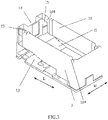
- a miniaturized high-power magnetic latching relay of the present disclosure includes a base 1, a magnetic circuit portion 2, a pushing card 3, a contact portion 4 and a housing 5.
- the base 1 is provided with a first blocking wall 11 to divide the base 1 into an upper cavity 12 and a lower cavity 13, the magnetic circuit portion 2 is installed in the upper cavity 12 and the contact portion 4 is installed in the lower cavity 13 to achieve strong and weak electrical isolation;
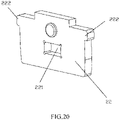
- the magnetic circuit portion 2 includes an iron core 21, two yokes 22, a magnetic steel 23 and an armature 24; the iron core 21 is strip-shaped and arranged horizontally, and the yoke 22 is plate-shaped.
- the two yokes 22 are respectively fixed on both ends of the iron core 21, and the magnetic steel 23 is matched in the middle of the iron core 21, after the assembly of the iron core 21, the yoke 22 and the magnetic steel 23 is completed, the iron core 21, the yoke 22 and the magnetic steel 23 can form an E-shaped magnetic conductive structure, that is, the shape of the magnetic conductive structure shown in FIG. 1 after being turned 90 degrees sideways.
- the middle position of the armature 24 is rotatably supported above the position corresponding to the magnetic steel 23, and the two ends of the armature 24 respectively correspond to the tops of the two yokes 22, so as to perform the seesaw type action in cooperation with the magnetic conductive structure; the upper end of the pushing card 3 is connected to one end of the armature 24, and the lower end of the pushing card 3 is connected to the free end of the movable spring 41 of the contact portion.
- the iron core 21 is a flat strip-shaped structure.
- a square through hole 221 is provided at the center of the each of the two yokes 22, the two yokes 22 are riveted and fixed to the two ends of the iron core 21 along the longitudinal direction L through the square through holes 221;
- two positioning protrusions 222 are provided on both sides of the yoke 22, the positioning protrusions 222 protrude outward from the top portion of the two sides of the yoke 22, and the positioning protrusions 222 as the positioning structure of the magnetic circuit portion 2 cooperate with the base 1.
- the top of the yoke 22 is arranged as a working pole surface matched with both ends of the armature 24.
- the iron core 21 is arranged to extend along the length direction L of the base 1, in the longitudinal direction L of the base 1, the front end of the base 1 is provided with a receiving groove 14 that is open toward the front and outside and is used to accommodate the pushing card 3.
- one end of the armature 24 extends from the above of the upper cavity 12 to the above of the receiving groove 14 and is connected to the upper end of the pushing card 3 accommodated in the receiving groove 14.
- the bottom of the receiving groove 14 communicates with the lower cavity 13 so that the lower end of the pushing card 3 accommodated in the receiving groove 14 is connected to the free end of the movable spring 41 of the contact portion 4 of the lower cavity 13.
- the "front” and “rear” in the present disclosure refer to the two sides along the length direction of the base 1 or the bobbin 251, as indicated by the arrow in FIG. 2 .
- the “front” and “rear” are only defined for the convenience of describing the structure of the magnetic latching relay, and are not limited. If the "front” is described as “rear”, the original “rear” becomes the “front”.
- the upper cavity 12 is a frame structure with a concave shape
- the front portion of the upper cavity 12 is arranged as a support platform 121 for supporting the front of the magnetic circuit portion 2
- the rear portion 122 of the upper cavity 12 is arranged as a sink slot for matching the coil structure 25 of the magnetic circuit portion, and a ramp-shaped web 123 is formed between the front portion and the rear portion.
- both sides of the front and rear ends of the upper cavity 12 are respectively provided with notches 124 for assembling the magnetic circuit portion 2 to achieve positioning.
- the positioning protrusions 222 on both sides of the two yokes 22 of the magnetic circuit portion 2 are respectively fitted in the notches 124 on both sides of the front and rear ends of the upper cavity 12.
- Dispensing gates 15 are respectively provided on both sides of the receiving groove 14 to fix the magnetic circuit portion 2 when the magnetic circuit portion 2 is inserted into the upper cavity 12 and the clamping force is insufficient.
- the lower cavity 13 is provided with openings communicating with the outside along the width direction W of the base 1, the movable spring 41 and the stationary spring 42 in the contact portion 4 are respectively inserted into the lower cavity 13 from two openings along the width direction W of the base 1, and are fixed by being inserted and connected through the horizontal slots provided in the lower cavity 13.
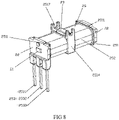
- the coil structure 25 includes a bobbin 251;
- the bobbin 251 includes flanges 2511 at both ends of the bobbin 251 along the length direction L (the length direction of the bobbin 251 is the same as the longitudinal direction of the base 1), a winding window portion 2512 between the flanges 2511 at both ends and an iron core mounting hole 2513 penetrating through the flanges 2511 at both ends of the bobbin 251 along the length direction L;
- the winding window portion 2512 is rod-shaped and hollow, a retaining wall 2514 is also provided in the middle of the winding window portion 2512 of the bobbin 251 to divide the winding window portion 2512 of the bobbin 251 into isolated first winding window portion 25121 and a second winding window portion 25122.
- the top surface of the retaining wall 2514 is provided with a recess 2515 recessed downward, and the recess 2515 communicates with the iron core mounting hole 2513; the iron core 21 is installed inside the winding window portion 2512, and both ends of the iron core 21 are installed in the iron core mounting hole 2513, as shown in FIG. 8 , two yokes 22 are respectively fitted at the outside of the flanges 2511 at both ends of the bobbin 251, and the magnetic steel 23 is installed in the recess 2515. As shown in FIG.
- limiting lug bosses 2516 are provided on both sides of the recess 2515 to restrict the movement of the magnetic steel 23 inserted into the recess 2515 along the width direction W of the bobbin 251 (the width direction of the bobbin 251 is the same as the width direction of the base).
- a shaft component 26 is also installed in the middle of the armature 24 so that both ends of the armature 24 have a seesaw structure.
- Shafts 261 are provided on both sides of the shaft component 26 respectively, as shown in FIG. 12 , the top of the limiting lug boss 2516 is provided with a semi-circular notch 2517 for installing the shaft 261 of the armature 24 to match the shaft 261 of the shaft component 26 of the armature 24 to restrict the movement of the shaft 261 of the armature 24 along the length direction L of the bobbin 251.
- a plurality of giving way notches 241 are provided on both sides distributed along the width direction of the armature 24, specifically, the giving way notches 241 extend from a position of the armature 24 near one end to a position of the armature 24 near the middle, to facilitate installation of the shaft component 26, the shaft component 26 is inserted into the armature 24 through the giving way notches 241, and is moved to the middle to form an interference fit with the armature 24, two limiting protrusions 242 are provided on both sides of the middle portion of the armature 24 near the other end of the armature 24 in the width direction to limit the movement of the shaft component 26 in the direction of toward one end of the armature 24.
- the coil structure 25 further includes an enameled wire 252 and a coil terminal 253;
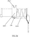
- the coil terminal 253 includes a start terminal 2531, a common terminal 2532, and an end terminal 2533, the three terminals are installed side by side along the width direction W of the bobbin 251 in the flange 2511 on the side close to the first winding window portion 25121, and the three coil terminals 253 have the same orientation.
- a wire groove 2518 for connecting the first winding window portion 25121 and the second winding window portion 25122 is provided on the retaining wall 2514, and a bridge terminal 254 (as shown in FIG.
- the enameled wire 252 starts from the start terminal 2531 and is wound by a single-coil method or a double-coil method, and then is connected to a bridge terminal 254, and is connected to the end terminal 2533 across the first winding window portion 25121 through the bridge terminal 254, so that the wound start wire 2521 and the end wire 2522 are spatially separated.
- the enameled wire 252 when use the single-coil method to wind the coil, drawing out the enameled wire 252 from the start terminal 2531, and then winding the first coil on the first winding window portion 25121, after winding the first coil, dragging the enameled wire 252 to the second winding window portion 25122 to wind the second coil, after winding the second coil, the enameled wire 252 is connected to the bridge terminal 254, and then is connected to the end terminal 2533 across the first winding window portion 25121 through the bridge terminal 254, so that the wound start wire 2521 and the end wire 2522 are spatially separated.
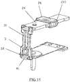
- the pushing card 3 is provided with two connecting arms 31 with a certain distance therebetween and a certain length, the two connecting arms are formed by the upper portion of the pushing card 3 protruding upwards, so that the two connecting arms 31 can be flexibly expanded to make the two sides of the armature 24 in the width direction be snapped into the pushing card 3 (that is, snapped between the two connecting arms 31), and realize that when the armature 24 swings up and down, the pushing card 3 is driven to move up and down.
- the lower portion of the pushing card 3 is provided with a substantially rectangular through hole 32, and the end of the movable spring 41 provided with a movable contact is movably hooked in the through hole 32 of the lower portion of the pushing card 3, when the pushing card 3 moves up and down, the end of the movable spring 41 with the movable contact swings up and down (as shown in FIG. 15 ).
- the upper and lower hole walls of the through hole 32 of the pushing card 3 are respectively designed as a circular arc surface, so that when the pushing card 3 moves, the pushing card 3 and the movable spring 41 come into line-to-surface contact, the distance between the upper hole wall and the lower hole wall of the through hole 32 is greater than the thickness of the end of the movable spring 41 where the movable contact is provided.
- substantially in the present disclosure means approximately, for example, substantially rectangular means not strictly rectangular, it may be a rectangle with chamfers, or a square, which is not particularly limited.
- a miniaturized high-power magnetic latching relay of some embodiments of the present disclosure adopts that a first blocking wall 11 is provided on the base 1 to divide the base 1 into an upper cavity 12 and a lower cavity 13, the magnetic circuit portion 2 and the contact portion 4 are respectively installed in the upper cavity 12 and the lower cavity 13 so as to achieve strong and weak electrical isolation.
- the present disclosure also adopts that the two yokes 22 are fixed to the two ends of the iron core 21, and the magnetic steel 23 is matched in the middle of the iron core 21, after the assembly of the iron core 21, the yokes 22, and the magnetic steel 23 is completed, the iron core 21, the yokes 22 and the magnetic steel 23 form an E-shaped magnetic conductive structure, that is, the shape of the magnetic conductive structure shown in FIG.
- the middle position of the armature 24 is rotatably supported above the position corresponding to the magnetic steel 23, and the two ends of the armature 24 correspond to the two yokes 22 respectively, so as to perform the seesaw type movement in cooperation with the magnetic conductive structure, and the upper end of the pushing card 3 is connected to one end of the armature 24, and the lower end of the pushing card 3 is connected to the free end of the movable spring 41 of the contact portion 4.
- the structure of the present disclosure has the characteristics of simple parts structure but complete functions, small product size and large load capacity.
- a miniaturized high-power magnetic latching relay of the present disclosure adopts that the upper cavity 12 of the base 1 is designed as a concave frame structure, and the lower cavity 13 is provided with openings communicating with the outside (that is, the left and right core pulling structure) along the width direction W of the base 1, which can realize that the mold structure is simple and the manufacturing cost is low.
- two second blocking walls are provided at positions corresponding to the matching of the movable spring 41 and the stationary spring 42 in the lower cavity 13, so as to utilize the air gap between the two second blocking walls 131 and the two second blocking walls 131 to achieve the isolation between the movable spring 41 and the stationary spring 42 to effectively increase the insulation distance between the movable spring 41 and the stationary spring 42 and to prevent the insulation from falling between the movable spring 41 and the stationary spring 42 at the end of life due to contact splashes and the risk of fire.
- the miniaturized high-power magnetic latching relay of the present disclosure adopts that the pushing card 3 is provided with two connecting arms 31 with a certain distance therebetween and a certain length, and the lower portion of the pushing card 3 is provided with a substantially rectangular through hole 32, the end of the movable spring 41 provided with a movable contact is movably hooked in the through hole 32 of the lower portion of the pushing card 3, and the upper and lower hole walls of the through hole 32 of the pushing card 3 are respectively designed as a circular arc surface, the distance between the upper wall and the lower wall of the through hole 32 is greater than the thickness of the end of the movable spring 41 where the movable contact is provided.
- the two connecting arms 31 can be flexibly expanded to make the two sides of the armature 24 in the width direction be snapped into the pushing card 3, and realize that when the armature 24 swings up and down, the pushing card 3 is driven to move up and down, and when the pushing card 3 moves, the pushing card 3 and the movable spring 41 come into line-to-surface contact, and a certain free stroke can be formed, so that when the relay opens the contacts, it has a certain acceleration process, which can better open the contacts, thereby improving the ability of the relay to resist surge current.
- the magnetic latching relay of the present disclosure has the following beneficial effects:
- the coil structure generally includes a bobbin, an enameled wire, and coil terminals.
- the bobbin includes flanges at both ends and a winding window portion between the flanges at both ends.
- the enameled wire is wound in the winding window portion of the bobbin, because the coil terminals are located at one of the flanges of the bobbin, after the enameled wire is wound, its start wire and end wire need to be led to one of the flanges of the bobbin to connect with the coil terminal, which easily causes the start and end wires of the enameled wire to overlap together, especially, the coil structure in the magnetic latching relay also adopts the double coil structure, which is more likely to cause the start and end wires of the enameled wire to overlap together.
- the reverse voltage easily breaks down the lap of the start wire and the end wire (when the start wire and end wire are lapped together, it is easy to form a voltage difference), causing the coil to short-circuit, resulting in the loss of relay function.
- the start terminal, the common terminal and the end terminal are usually arranged on three flanges, in the case of a small product volume, the distance between the terminal of the coil and the movable and stationary springs is too short to meet the requirements of reinforced insulation.
- the distance between the strong and weak electricity is short, which is not conducive to the isolation of the strong and weak electricity, and it is easy to cause breakdown between the strong and weak electricity and cause the risk of short circuit, and if the user needs to install multiple products closely, considering the isolation of strong and weak electricity, the PCB board size will become very large.
- this embodiment provides a coil structure including a bobbin 251, an enameled wire 252 and a coil terminal 253.
- the bobbin 251 includes flanges 2511 provided at both ends thereof along the longitudinal direction L (the longitudinal direction of the bobbin 251 is the same as the longitudinal direction of the base 1), and a winding window portion 2512 between the flanges 2511 at both ends, and an iron core mounting hole 2513 penetrating the flanges 2511 at both ends along the length direction L.
- the iron core 21 is installed inside the winding window portion 2512, and both ends of the iron core 21 are installed in the iron core mounting hole 2513 of the bobbin 251, both ends of the iron core 21 are fixed to the two yokes 22 by riveting outside the iron core mounting hole 2513, both ends of the iron core 21 are fixed to the yoke 22 by riveting outside the iron core mounting hole 2513.
- a retaining wall 2514 is further provided to divide the winding window portion 2512 of the bobbin 251 into isolated first winding window portion 25121 and a second winding window portion 25122;
- the coil terminal 253 includes a start terminal 2531, a common terminal 2532, and an end terminal 2533, the three terminals are installed side by side along the width direction W of the bobbin 251 in the flange 2511 on the side close to the first winding window portion 25121, and the three coil terminals 253 have the same orientation. As shown in FIG.
- a wire groove 2518 for connecting the first winding window portion 25121 and the second winding window portion 25122 is provided on the retaining wall 2514, and a bridge terminal 254 (as shown in FIG. 26 ) is installed in the retaining wall 2514, and the orientation of the bridge terminal 254 is the same as the orientation of the three terminals.
- the enameled wire 252 starts from the start terminal 2531 and is wound by a single-coil method or a double-coil method, and then is connected to a bridge terminal 254, and is connected to the end terminal 2533 across the first winding window portion 25121 through the bridge terminal 254, so that the wound start wire 2521 and the end wire 2522 are spatially separated.
- three terminal holes 2611 for inserting the three terminals are provided in the flange 2511 on the side close to the first winding window portion 25121, the three terminal holes 2611 are arranged at regular intervals along the width direction W of the bobbin 251.
- the three terminals such as the start terminal 2531, the common terminal 2532, and the end terminal 2533 are inserted into the corresponding terminal holes 2611, respectively, the common terminal 2532 is inserted into the terminal hole 2611 in the middle position among the three terminal holes 2611.
- the cross-sectional shape of the winding window portion 2512 is substantially rectangular, and the retaining wall 2514 is substantially rectangular shape.
- the wire groove 2518 and the bridge terminal 254 are respectively provided on the bottom surface of the retaining wall 2514.
- a first slot 25141 is provided at the connection position corresponding to the bridge terminal 254, the bridge terminal 254 is inserted into the first slot 25141 of the retaining wall 2514, and both of them are in an interference fit.
- the wire groove 2518 is diagonally connected between the first winding window portion 25121 and the second winding window portion 25122.
- the positions connected to the first winding window portion 25121 and the second winding window portion 25122 are respectively set in an arc-shaped structure to avoid scratching the enameled wire.
- the top surface of the retaining wall 2514 is provided with a recess 2515 that is recessed downwards and used to install magnetic steel.
- the recess 2515 communicates with the iron core mounting hole 2513.
- limiting lug bosses 2516 are provided on both sides of the recess 2515 to restrict the movement of the magnetic steel 23 inserted into the recess 2515 along the width direction W of the bobbin 251 (the width direction of the bobbin 251 is the same as the width direction of the base), in one embodiment, there are two limiting lug bosses 2516.
- the top of the limiting lug boss 2516 is provided with a semi-circular notch 2517 for installing the shaft 261 of the armature 24 to match the shaft 261 of the shaft component 26 of the armature 24 to restrict the movement of the shaft 261 of the armature 24 along the length direction L of the bobbin 251.
- the relay may adopt the single-coil method to wind the coil or the double-coil method to wind the coil.
- a retaining wall 2514 is further provided in the middle of the winding window portion 2512 of the bobbin 251 to divide the winding window portion 2512 of the bobbin 251 into an isolated first winding window portion 25121 and a second winding window portion 25122;
- the coil terminal 253 includes a start terminal 2531, a common terminal 2532, and an end terminal 2533, the three terminals are installed side by side along the width direction W of the bobbin 251 in the flange 2511 on the side close to the first winding window portion 25121, and the three terminals have the same orientation.
- a wire groove 2518 for connecting the first winding window portion 25121 and the second winding window portion 25122 is provided on the retaining wall 2514, and a bridge terminal 254 is installed in the retaining wall 2514, and the orientation of the bridge terminal 254 is the same as the orientation of the three coil terminals 253.
- the enameled wire 252 starts from the start terminal 2531 and is wound by a single-coil method or a double-coil method, and then is connected to a bridge terminal 254, and is connected to the end terminal 2533 across the first winding window portion 25121 through the bridge terminal 254, so that the wound start wire 2521 and the end wire 2522 are spatially separated.
- the structure of the present disclosure can effectively avoid the shortcomings of the coil short circuit caused by the overlapping of the start and end wires of the enameled wire 252, and can also meet the strong and weak electrical isolation requirements when the product is applied to a large current occasion.
- the coil terminal 253 has a large distance from the movable spring 41 and the stationary spring 42, which not only can achieve the function of strengthening insulation in a small volume, but also can meet the user's strong and weak electrical isolation requirements for tight installation of multiple products without increasing the PCB area.
- the coil structure 25 further includes an enameled wire 252 and a coil terminal 253;
- the coil terminal 253 includes a start terminal 2531, a common terminal 2532, and an end terminal 2533, the three terminals are installed side by side along the width direction W of the bobbin 251 in the flange 2511 on the side close to the first winding window portion 25121, and the three coil terminal 253 has the same orientation, a wire groove 2518 for connecting the first winding window portion 25121 and the second winding window portion 25122 is provided on the retaining wall 2514, and a bridge terminal 254 is installed in the retaining wall 2514, and the orientation of the bridge terminal 254 is the same as the orientation of the three terminal;
- the enameled wire 252 starts from the start
Landscapes
- Physics & Mathematics (AREA)
- Electromagnetism (AREA)
- Electromagnets (AREA)
Claims (15)
- Magnetisches Verriegelungsrelais, umfassend: eine Basis (1), einen Magnetkreisabschnitt (2), eine Schiebekarte (3) und einen Kontaktabschnitt (4); wobei die Basis (1) mit einer ersten Sperrwand (11) versehen ist, um die Basis (1) in einen oberen Hohlraum (12) und einen unteren Hohlraum (13) zu unterteilen, der Magnetkreisabschnitt (2) in dem oberen Hohlraum (12) installiert ist und der Kontaktabschnitt (4) in dem unteren Hohlraum (13) installiert ist; wobei der Magnetkreisabschnitt (2) einen Eisenkern (21), zwei Joche (22), einen Magnetstahl (23) und einen Anker (24) umfasst; wobei der Eisenkern (21) streifenförmig und horizontal angeordnet ist und die zwei Joche (22) plattenförmig sind, undwodurch die zwei Joche (22) jeweils an beiden Enden des Eisenkerns (21) fixiert sind unddadurch gekennzeichnet, dasssich der Magnetstahl (23) in der Mitte des Eisenkerns (21) befindet, sodass der Eisenkern (21), die zwei Joche (22) und der Magnetstahl (23) so angeordnet sind, dass sie eine E-förmige magnetisch leitfähige Struktur bilden, die um 90 Grad gegen den Uhrzeigersinn gedreht ist;der Mittelabschnitt des Ankers (24) drehbar über dem Magnetstahl (23) gestützt ist und sich jedes Ende des Ankers (24) über einer oberen Oberfläche von jeweiligen der zwei Joche (22) befindet, um eine Aktion vom Typ einer Wippe in Zusammenwirkung mit der magnetisch leitfähigen Struktur durchzuführen; undein oberes Ende der Schiebekarte (3) mit einem Ende des Ankers (24) verbunden ist und ein unteres Ende der Schiebekarte (3) mit einem freien Ende einer beweglichen Feder (41) des Kontaktabschnitts (4) verbunden ist.
- Magnetisches Verriegelungsrelais nach Anspruch 1, wobei der Eisenkern (21) eine flache streifenförmige Struktur ist, ein quadratisches Durchgangsloch (221) am Mittelpunkt jedes der zwei Joche (22) bereitgestellt ist, die zwei Joche (22) an den zwei Enden des Eisenkerns (21) entlang der Längsrichtung (L) durch das quadratische Durchgangsloch (221) vernietet und fixiert sind;zwei Positionierungsvorsprünge (222) auf beiden Seiten jedes der zwei Joche (22) bereitgestellt sind, die Positionierungsvorsprünge (222) dazu konfiguriert sind, den Magnetkreisabschnitt (2) in Bezug auf die Basis (1) zu positionieren; unddie obere Oberfläche jedes der zwei Joche (22) so angeordnet ist, dass sie mit jeweiligen Enden des Ankers (24) als Arbeitspoloberfläche zusammenwirkt.
- Magnetisches Verriegelungsrelais nach Anspruch 1, wobei der Eisenkern (21) so angeordnet ist, dass er sich entlang der Längenrichtung (L) der Basis (1) erstreckt,eine Aufnahmenut (14) auf einer vorderen Oberfläche der Basis (1) bereitgestellt ist und eine Öffnung einschließt, die dazu konfiguriert ist, mit der Außenseite der Basis (1) zu kommunizieren und die Schiebekarte (3) unterzubringen,ein Ende des Ankers (24) dazu konfiguriert ist, sich von oberhalb des oberen Hohlraums (12) bis oberhalb der Aufnahmenut (14) zu erstrecken und mit dem oberen Ende der in der Aufnahmenut (14) untergebrachten Schiebekarte (3) verbunden zu werden; undder Boden der Aufnahmenut (14) dazu konfiguriert ist, mit dem unteren Hohlraum (13) zu kommunizieren, sodass das untere Ende der in der Aufnahmenut (14) untergebrachten Schiebekarte (3) mit einem freien Ende der beweglichen Feder (41) des Kontaktabschnitts (4) im unteren Hohlraum (13) verbunden ist.
- Magnetisches Verriegelungsrelais nach Anspruch 3, wobei der obere Hohlraum (12) eine Rahmenstruktur mit einer konkaven Form ist und ein vorderer Abschnitt des oberen Hohlraums (12) als Stützplattform (121) zum Stützen der Vorderseite des Magnetkreisabschnitts (2) angeordnet ist, ein hinterer Abschnitt (122) des oberen Hohlraums (12) als Senkschlitz zum Unterbringen der Spulenstruktur (25) des Magnetkreisabschnitts (2) angeordnet ist und ein rampenförmiger Steg (123) zwischen dem vorderen Abschnitt und dem hinteren Abschnitt (122) gebildet ist.
- Magnetisches Verriegelungsrelais nach Anspruch 3, wobei beide Seiten eines vorderen Endes und eines hinteren Endes des oberen Hohlraums (12) jeweils mit Kerben (124) zum Zusammenbauen des Magnetkreisabschnitts (2) versehen sind, um Positionierung zu erreichen; und
Schieber (15) jeweils in dem oberen Hohlraum (12) auf beiden Seiten der Aufnahmenut (14) bereitgestellt und so angeordnet sind, dass sie Nuten bilden, die dazu konfiguriert sind, die Position des Magnetkreisabschnitts (2) zu fixieren, wenn der Magnetkreisabschnitt (2) in den oberen Hohlraum (12) eingesetzt ist. - Magnetisches Verriegelungsrelais nach Anspruch 1, wobei der untere Hohlraum (13) mit zwei Öffnungen versehen ist, die entlang einer Breitenrichtung (W) der Basis (1) mit der Außenseite kommunizieren, die bewegliche Feder (41) und eine stationäre Feder (42) in dem Kontaktabschnitt (4) von den zwei Öffnungen aus entlang der Breitenrichtung (W) der Basis (1) jeweils in den unteren Hohlraum (13) eingesetzt werden und fixiert werden, indem sie durch in dem unteren Hohlraum (13) bereitgestellte horizontale Schlitze eingesetzt und verbunden werden; und
wobei es zwei zweite Sperrwände (131) an Positionen gibt, die der beweglichen Feder (41) bzw. der stationären Feder (42) entsprechen, um eine Isolierung zwischen der beweglichen Feder (41) und der stationären Feder (42) umzusetzen, indem die zwei zweiten Sperrwände (131) und ein Luftspalt zwischen den zwei zweiten Sperrwänden (131) verwendet werden. - Magnetisches Verriegelungsrelais nach Anspruch 4, wobei die Spulenstruktur (25) einen Spulenkörper (251) umfasst;der Spulenkörper (251) Flansche (2511) an beiden Enden entlang der Längenrichtung (L), einen Wickelfensterabschnitt (2512) zwischen den Flanschen (2511) an beiden Enden und ein Eisenkern-Montageloch (2513), das die Flansche (2511) an beiden Enden entlang der Längenrichtung (L) durchdringt, umfasst;der Wickelfensterabschnitt (2512) stabförmig und hohl ist; eine Haltewand (2514) ebenfalls in der Mitte des Wickelfensterabschnitts (2512) des Spulenkörpers (251) bereitgestellt ist, um den Wickelfensterabschnitt (2512) des Spulenkörpers (251) in einen isolierten ersten Wickelfensterabschnitt (25121) und zweiten Wickelfensterabschnitt (25122) zu unterteilen;eine obere Oberfläche der Haltewand (2514) mit einer nach unten ausgesparten Aussparung (2515) versehen ist und die Aussparung (2515) dazu konfiguriert ist, mit dem Eisenkern-Montageloch (2513) zu kommunizieren;der Eisenkern (21) innerhalb des Wickelfensterabschnitts (2512) installiert ist und beide Enden des Eisenkerns (21) in dem Eisenkern-Montageloch (2513) installiert sind, die zwei Joche (22) jeweils an der Außenseite der Flansche (2511) an beiden Enden des Spulenkörpers (251) angebracht sind und der Magnetstahl (23) in der Aussparung (2515) installiert ist; undBegrenzungsansätze (2516) an beiden Seitenwänden der Aussparung (2515) bereitgestellt sind, um eine Bewegung des in die Aussparung (2515) eingesetzten Magnetstahls (23) entlang einer Breitenrichtung (W) des Spulenkörpers (251) einzuschränken.
- Magnetisches Verriegelungsrelais nach Anspruch 7, wobei eine Wellenkomponente (26) in der Mitte des Ankers (24) installiert ist, sodass beide Enden des Ankers (24) eine Wippenstruktur aufweisen;Wellen (261) jeweils auf beiden Seiten der Wellenkomponente (26) bereitgestellt sind und die obere Oberfläche jeder Seite der Haltewand (2514) in der Breitenrichtung (W) des Spulenkörpers (251) mit einer halbkreisförmigen Kerbe (2517) zum Installieren jeweiliger Wellen (261) der Wellenkomponente (26) des Ankers (24) versehen sind, um die Bewegung der Wellen (261) in einer Längenrichtung (L) des Spulenkörpers (251) einzuschränken; undKerben (241) an beiden Seitenkanten des Ankers (24) in der Breitenrichtung (W) des Ankers (24) bereitgestellt sind, die Kerben (241) dazu konfiguriert sind, sich in der Längenrichtung (L) des Ankers (24) von einer Position nahe einem Ende des Ankers (24) zu einer Position nahe der Mitte des Ankers (24) zu erstrecken, um die Installation der Wellenkomponente (26) zu erleichtern, die Wellenkomponente (26) in den Anker (24) durch die Kerben (241) eingesetzt wird und zur Mitte des Ankers (24) bewegt wird, um eine Presspassung mit dem Anker (24) zu bilden, zwei Begrenzungsvorsprünge (2517) auf beiden Seiten des Mittelabschnitts des Ankers (24) bereitgestellt sind, um die Bewegung der Wellenkomponente (26) in einer Richtung hin zu einem Ende des Ankers (24) zu begrenzen.
- Magnetisches Verriegelungsrelais nach Anspruch 7, wobei die Spulenstruktur (25) ferner einen Lackdraht (252) und einen Spulenanschluss (253) umfasst;der Spulenanschluss (253) einen Anfangsanschluss (2531), einen gemeinsamen Anschluss (2532) und einen Endanschluss (2533) umfasst, die drei Anschlüsse (2531, 2532, 2533) Seite an Seite entlang der Breitenrichtung (W) des Spulenkörpers (251) in einem Flansch (2511) auf einer Seite in der Nähe des ersten Wickelfensterabschnitts (25121) installiert sind und die drei Anschlüsse (2531, 2532, 2533) die gleiche Ausrichtung aufweisen;eine Drahtnut (2518) zum Verbinden des ersten Wickelfensterabschnitts (25121) und des zweiten Wickelfensterabschnitts (25122) an der Haltewand (2514) bereitgestellt ist und ein Brückenanschluss (254) in der Haltewand (2514) installiert ist und die Ausrichtung des Brückenanschlusses (254) die gleiche wie die Ausrichtung der drei Anschlüsse (2531, 2532, 2533) ist; undder Lackdraht (252) dazu konfiguriert ist, von dem Anfangsanschluss (2531) anzufangen und mit dem Brückenanschluss (254) verbunden zu werden, nachdem er durch ein Einzelspulenverfahren oder ein Doppelspulenverfahren gewickelt worden ist, und mit dem Endanschluss (2533) über den ersten Wickelfensterabschnitt (25121) durch den Brückenanschluss (254) verbunden ist, sodass ein Anfangsabschnitt (2521) und ein Endabschnitt (2522) des Lackdrahts (252) räumlich getrennt sind, wenn sie gewickelt sind.
- Magnetisches Verriegelungsrelais nach Anspruch 9, wobei drei Anschlusslöcher (2611) zum Einsetzen der drei Anschlüsse (2531, 2532, 2533) in dem Flansch (2511) auf einer Seite in der Nähe des ersten Wickelfensterabschnitts (25121) bereitgestellt sind,die drei Anschlusslöcher (2611) in regelmäßigen Intervallen entlang der Breitenrichtung (W) des Spulenkörpers (251) angeordnet sind undder gemeinsame Anschluss (2532) in ein Anschlussloch (2611) eingesetzt ist, das sich in einer mittleren Position zwischen den drei Anschlusslöchern (2611) befindet.
- Magnetisches Verriegelungsrelais nach Anspruch 10, wobei, wenn der Lackdraht (252) gemäß dem Einzelspulenverfahren gewickelt ist, der Lackdraht (252) so angeordnet ist, dass sequentiell von dem Anfangsanschluss (2531) der Anfangsabschnitt (2521) auf den ersten Wickelfensterabschnitt (25121) gewickelt ist, sich ein zweiter Abschnitt durch die Drahtnut (2518) erstreckt und auf den zweiten Wickelfensterabschnitt (25122) gewickelt ist, ein dritter Abschnitt mit dem Brückenanschluss (254) verbunden ist, sich ein vierter Abschnitt durch den Brückenanschluss (254) und über den ersten Wickelfensterabschnitt (25121) erstreckt und der Endabschnitt (2522) mit dem Endanschluss (2533) verbunden ist, sodass der Anfangsabschnitt (2521) und der Endabschnitt (2522) räumlich getrennt sind.
- Magnetisches Verriegelungsrelais nach Anspruch 10, wobei, wenn der Lackdraht (252) gemäß dem Doppelspulenverfahren gewickelt ist, der Lackdraht (252) so angeordnet ist, dass sequentiell von dem Anfangsanschluss (2531) der Anfangsabschnitt (2521) auf den ersten Wickelfensterabschnitt (25121) gewickelt ist, ein zweiter Abschnitt mit dem gemeinsamen Anschluss (2532) verbunden ist, ein dritter Abschnitt mit wenigen Windungen mit einer Stufe mit einer großen Steigung auf den ersten Wickelfensterabschnitt (25121) gewickelt ist, sich ein vierter Abschnitt durch die Drahtnut (2518) erstreckt und auf den zweiten Wickelfensterabschnitt (25122) gewickelt ist, ein fünfter Abschnitt mit dem Brückenanschluss (254) verbunden ist, sich ein sechster Abschnitt durch den Brückenanschluss (254) und über den ersten Wickelfensterabschnitt (25121) erstreckt und der Endabschnitt (2522) mit dem Endanschluss (2533) verbunden ist, sodass der Anfangsabschnitt (2521) und der Endabschnitt (2522) räumlich getrennt sind.
- Magnetisches Verriegelungsrelais nach einem der Ansprüche 9 bis 12, wobei eine Querschnittsform des Wickelfensterabschnitts (2512) im Wesentlichen rechteckig ist und die Haltewand (2514) eine im Wesentlichen rechteckige Form aufweist, die Drahtnut (2518) und der Brückenanschluss (254) an einer Bodenoberfläche der Haltewand (2514) bereitgestellt sind, ein erster Schlitz an einer Verbindungsposition bereitgestellt ist, die dem Brückenanschluss (254) entspricht, der Brückenanschluss (254) in den ersten Schlitz der Haltewand (2514) eingesetzt ist, um eine Presspassung mit dem ersten Schlitz zu bilden; und
wobei die Drahtnut (2518) diagonal zwischen dem ersten Wickelfensterabschnitt (25121) und dem zweiten Wickelfensterabschnitt (25122) verbunden ist. - Magnetisches Verriegelungsrelais nach Anspruch 11, wobei in Nutwänden auf beiden Seiten der Drahtnut (2518) Positionen, die mit dem ersten Wickelfensterabschnitt (25121) und dem zweiten Wickelfensterabschnitt (25122) verbunden sind, jeweils in einer bogenförmigen Struktur liegen.
- Magnetisches Verriegelungsrelais nach Anspruch 1, wobei die Schiebekarte (3) mit zwei Verbindungsarmen (31) mit einem gewissen Abstand dazwischen und einer gewissen Länge versehen ist, die zwei Verbindungsarme (31) durch einen oberen Abschnitt der Schiebekarte (3) gebildet sind, der nach oben vorspringt, sodass die zwei Verbindungsarme (31) flexibel erweitert werden können, um zu bewirken, dass zwei Seiten des Ankers (24) in der Breitenrichtung (W) zwischen den zwei Verbindungsarmen (31) einschnappen, und umzusetzen, dass, wenn der Anker (24) nach oben und unten schwingt, die Schiebekarte (3) so angetrieben wird, dass sie sich nach oben und unten bewegt;wobei ein unterer Abschnitt der Schiebekarte (3) mit einem im Wesentlichen rechteckigen Durchgangsloch (32) versehen ist und ein Ende der beweglichen Feder (41), das mit einem beweglichen Kontakt versehen ist, beweglich in das Durchgangsloch (32) des unteren Abschnitts der Schiebekarte (3) eingehakt ist, wenn sich die Schiebekarte (3) nach oben und unten bewegt, das Ende der beweglichen Feder (41) mit dem beweglichen Kontakt nach oben und unten schwingt; undeine obere Lochwand und eine untere Lochwand des Durchgangslochs der Schiebekarte (3) jeweils in einer Form einer Kreisbogenoberfläche angeordnet sind, sodass, wenn sich die Schiebekarte (3) bewegt, die Schiebekarte (3) und die bewegliche Feder (41) in Linien-Oberflächen-Kontakt kommen, ein Abstand zwischen der oberen Lochwand und der unteren Lochwand des Durchgangslochs (32) größer ist als eine Dicke des Endes der beweglichen Feder (41), wo der bewegliche Kontakt bereitgestellt ist.
Applications Claiming Priority (2)
| Application Number | Priority Date | Filing Date | Title |
|---|---|---|---|
| CN201910614479.0A CN110335787B (zh) | 2019-07-09 | 2019-07-09 | 一种线圈及其磁保持继电器 |
| CN201910614496.4A CN110335788B (zh) | 2019-07-09 | 2019-07-09 | 一种小型化大功率磁保持继电器 |
Publications (2)
| Publication Number | Publication Date |
|---|---|
| EP3764385A1 EP3764385A1 (de) | 2021-01-13 |
| EP3764385B1 true EP3764385B1 (de) | 2022-08-10 |
Family
ID=71170343
Family Applications (1)
| Application Number | Title | Priority Date | Filing Date |
|---|---|---|---|
| EP20182368.9A Active EP3764385B1 (de) | 2019-07-09 | 2020-06-25 | Magnetisches verriegelungsrelais |
Country Status (2)
| Country | Link |
|---|---|
| US (1) | US11501938B2 (de) |
| EP (1) | EP3764385B1 (de) |
Families Citing this family (3)
| Publication number | Priority date | Publication date | Assignee | Title |
|---|---|---|---|---|
| CN112885646B (zh) | 2021-01-15 | 2025-09-26 | 厦门宏发电力电器有限公司 | 一种拍合式双稳态磁路结构及磁保持继电器 |
| CN112992610B (zh) * | 2021-02-08 | 2022-07-29 | 四川宏发电声有限公司 | 一种卧式继电器的推动卡装配结构 |
| CN118448217A (zh) * | 2024-06-07 | 2024-08-06 | 厦门宏发电声股份有限公司 | 一种线圈部分及电磁继电器 |
Family Cites Families (14)
| Publication number | Priority date | Publication date | Assignee | Title |
|---|---|---|---|---|
| US2924684A (en) * | 1955-03-11 | 1960-02-09 | Claesson Per Harry Elias | Contact device |
| CA1253182A (en) * | 1985-10-25 | 1989-04-25 | Yuichi Kamo | Polarized electromagnetic relay |
| DE9013221U1 (de) * | 1990-09-18 | 1992-01-23 | Siemens AG, 80333 München | Elektromagnetisches Leistungsrelais mit Betätigungsschieber |
| WO1995008180A1 (en) * | 1993-09-17 | 1995-03-23 | Omron Corporation | Electromagnetic relay and its manufacture |
| JP2606096B2 (ja) * | 1993-09-21 | 1997-04-30 | 日本電気株式会社 | 電磁リレー |
| US5805039A (en) * | 1995-08-07 | 1998-09-08 | Siemens Electromechanical Components, Inc. | Polarized electromagnetic relay |
| JP3412358B2 (ja) * | 1995-09-27 | 2003-06-03 | オムロン株式会社 | 電磁石装置 |
| DE19606884C1 (de) | 1996-02-23 | 1997-04-30 | Schrack Components Ag | Elektromagnetisches Relais |
| KR100452659B1 (ko) * | 2000-03-28 | 2004-10-14 | 마츠시다 덴코 가부시키가이샤 | 전자기 구동 장치 및 전자기 릴레이 |
| JP4052015B2 (ja) * | 2002-05-23 | 2008-02-27 | オムロン株式会社 | 高周波リレー |
| CN2715327Y (zh) | 2003-07-23 | 2005-08-03 | 欧姆龙株式会社 | 电磁铁驱动装置和电磁继电器 |
| DE102010017874B4 (de) * | 2010-04-21 | 2013-09-05 | Saia-Burgess Dresden Gmbh | Bistabiler Magnetaktor |
| EP2648203A4 (de) | 2010-11-30 | 2014-12-03 | Fuji Elec Fa Components & Sys | Verriegelungsrelais |
| DE102012006438A1 (de) | 2012-03-30 | 2013-10-02 | Phoenix Contact Gmbh & Co. Kg | Relais mit zwei gegensinnig betätigbaren Schaltern |
-
2020
- 2020-06-24 US US16/910,605 patent/US11501938B2/en active Active
- 2020-06-25 EP EP20182368.9A patent/EP3764385B1/de active Active
Also Published As
| Publication number | Publication date |
|---|---|
| US11501938B2 (en) | 2022-11-15 |
| US20210012989A1 (en) | 2021-01-14 |
| EP3764385A1 (de) | 2021-01-13 |
Similar Documents
| Publication | Publication Date | Title |
|---|---|---|
| KR950001594Y1 (ko) | 전자 릴레이 | |
| CN110335788B (zh) | 一种小型化大功率磁保持继电器 | |
| CA2732295C (en) | Electromagnetic relay | |
| EP3764385B1 (de) | Magnetisches verriegelungsrelais | |
| US11114264B2 (en) | Insertion structure between static spring and bobbin | |
| US3727157A (en) | Electric control device | |
| CN110890250A (zh) | 一种可控制两路负载的小型化组合继电器 | |
| US12272508B2 (en) | Ultra-miniature hinge type relay having high dielectric strength between contacts and long service life | |
| CN210156327U (zh) | 小型化大功率磁保持继电器 | |
| CN210156326U (zh) | 线圈及其磁保持继电器 | |
| HK40041833B (en) | Magnetic latching relay | |
| HK40041833A (en) | Magnetic latching relay | |
| CN110473743B (zh) | 一种可保证衔铁或动簧片正常动作的继电器 | |
| CN118507300A (zh) | 继电器及电表 | |
| CN107492472B (zh) | 继电器 | |
| CN115642057A (zh) | 一种耐大负载的电磁继电器 | |
| EP3968351B1 (de) | Elektromagnetisches relais | |
| CN223566522U (zh) | 磁保持继电器组件 | |
| CN222813508U (zh) | 继电器 | |
| CN222813483U (zh) | 继电器 | |
| CN222320113U (zh) | 继电器及电表 | |
| CN223665382U (zh) | 一种继电器 | |
| CN220963150U (zh) | 一种电源控制磁保持继电器 | |
| CN219842931U (zh) | 增加爬电距离的继电器 | |
| CN223079049U (zh) | 一种动簧部分与推动卡连接结构及电磁继电器 |
Legal Events
| Date | Code | Title | Description |
|---|---|---|---|
| PUAI | Public reference made under article 153(3) epc to a published international application that has entered the european phase |
Free format text: ORIGINAL CODE: 0009012 |
|
| STAA | Information on the status of an ep patent application or granted ep patent |
Free format text: STATUS: REQUEST FOR EXAMINATION WAS MADE |
|
| 17P | Request for examination filed |
Effective date: 20200625 |
|
| AK | Designated contracting states |
Kind code of ref document: A1 Designated state(s): AL AT BE BG CH CY CZ DE DK EE ES FI FR GB GR HR HU IE IS IT LI LT LU LV MC MK MT NL NO PL PT RO RS SE SI SK SM TR |
|
| AX | Request for extension of the european patent |
Extension state: BA ME |
|
| REG | Reference to a national code |
Ref country code: HK Ref legal event code: DE Ref document number: 40041833 Country of ref document: HK |
|
| RIC1 | Information provided on ipc code assigned before grant |
Ipc: H01H 51/22 20060101AFI20220405BHEP |
|
| GRAP | Despatch of communication of intention to grant a patent |
Free format text: ORIGINAL CODE: EPIDOSNIGR1 |
|
| STAA | Information on the status of an ep patent application or granted ep patent |
Free format text: STATUS: GRANT OF PATENT IS INTENDED |
|
| INTG | Intention to grant announced |
Effective date: 20220516 |
|
| GRAS | Grant fee paid |
Free format text: ORIGINAL CODE: EPIDOSNIGR3 |
|
| GRAA | (expected) grant |
Free format text: ORIGINAL CODE: 0009210 |
|
| STAA | Information on the status of an ep patent application or granted ep patent |
Free format text: STATUS: THE PATENT HAS BEEN GRANTED |
|
| AK | Designated contracting states |
Kind code of ref document: B1 Designated state(s): AL AT BE BG CH CY CZ DE DK EE ES FI FR GB GR HR HU IE IS IT LI LT LU LV MC MK MT NL NO PL PT RO RS SE SI SK SM TR |
|
| REG | Reference to a national code |
Ref country code: AT Ref legal event code: REF Ref document number: 1511169 Country of ref document: AT Kind code of ref document: T Effective date: 20220815 Ref country code: CH Ref legal event code: EP |
|
| REG | Reference to a national code |
Ref country code: IE Ref legal event code: FG4D |
|
| REG | Reference to a national code |
Ref country code: DE Ref legal event code: R096 Ref document number: 602020004429 Country of ref document: DE |
|
| REG | Reference to a national code |
Ref country code: NL Ref legal event code: MP Effective date: 20220810 |
|
| REG | Reference to a national code |
Ref country code: LT Ref legal event code: MG9D |
|
| PG25 | Lapsed in a contracting state [announced via postgrant information from national office to epo] |
Ref country code: SE Free format text: LAPSE BECAUSE OF FAILURE TO SUBMIT A TRANSLATION OF THE DESCRIPTION OR TO PAY THE FEE WITHIN THE PRESCRIBED TIME-LIMIT Effective date: 20220810 Ref country code: RS Free format text: LAPSE BECAUSE OF FAILURE TO SUBMIT A TRANSLATION OF THE DESCRIPTION OR TO PAY THE FEE WITHIN THE PRESCRIBED TIME-LIMIT Effective date: 20220810 Ref country code: PT Free format text: LAPSE BECAUSE OF FAILURE TO SUBMIT A TRANSLATION OF THE DESCRIPTION OR TO PAY THE FEE WITHIN THE PRESCRIBED TIME-LIMIT Effective date: 20221212 Ref country code: NO Free format text: LAPSE BECAUSE OF FAILURE TO SUBMIT A TRANSLATION OF THE DESCRIPTION OR TO PAY THE FEE WITHIN THE PRESCRIBED TIME-LIMIT Effective date: 20221110 Ref country code: NL Free format text: LAPSE BECAUSE OF FAILURE TO SUBMIT A TRANSLATION OF THE DESCRIPTION OR TO PAY THE FEE WITHIN THE PRESCRIBED TIME-LIMIT Effective date: 20220810 Ref country code: LV Free format text: LAPSE BECAUSE OF FAILURE TO SUBMIT A TRANSLATION OF THE DESCRIPTION OR TO PAY THE FEE WITHIN THE PRESCRIBED TIME-LIMIT Effective date: 20220810 Ref country code: LT Free format text: LAPSE BECAUSE OF FAILURE TO SUBMIT A TRANSLATION OF THE DESCRIPTION OR TO PAY THE FEE WITHIN THE PRESCRIBED TIME-LIMIT Effective date: 20220810 Ref country code: FI Free format text: LAPSE BECAUSE OF FAILURE TO SUBMIT A TRANSLATION OF THE DESCRIPTION OR TO PAY THE FEE WITHIN THE PRESCRIBED TIME-LIMIT Effective date: 20220810 |
|
| REG | Reference to a national code |
Ref country code: AT Ref legal event code: MK05 Ref document number: 1511169 Country of ref document: AT Kind code of ref document: T Effective date: 20220810 |
|
| PG25 | Lapsed in a contracting state [announced via postgrant information from national office to epo] |
Ref country code: PL Free format text: LAPSE BECAUSE OF FAILURE TO SUBMIT A TRANSLATION OF THE DESCRIPTION OR TO PAY THE FEE WITHIN THE PRESCRIBED TIME-LIMIT Effective date: 20220810 Ref country code: IS Free format text: LAPSE BECAUSE OF FAILURE TO SUBMIT A TRANSLATION OF THE DESCRIPTION OR TO PAY THE FEE WITHIN THE PRESCRIBED TIME-LIMIT Effective date: 20221210 Ref country code: HR Free format text: LAPSE BECAUSE OF FAILURE TO SUBMIT A TRANSLATION OF THE DESCRIPTION OR TO PAY THE FEE WITHIN THE PRESCRIBED TIME-LIMIT Effective date: 20220810 Ref country code: GR Free format text: LAPSE BECAUSE OF FAILURE TO SUBMIT A TRANSLATION OF THE DESCRIPTION OR TO PAY THE FEE WITHIN THE PRESCRIBED TIME-LIMIT Effective date: 20221111 |
|
| PG25 | Lapsed in a contracting state [announced via postgrant information from national office to epo] |
Ref country code: SM Free format text: LAPSE BECAUSE OF FAILURE TO SUBMIT A TRANSLATION OF THE DESCRIPTION OR TO PAY THE FEE WITHIN THE PRESCRIBED TIME-LIMIT Effective date: 20220810 Ref country code: RO Free format text: LAPSE BECAUSE OF FAILURE TO SUBMIT A TRANSLATION OF THE DESCRIPTION OR TO PAY THE FEE WITHIN THE PRESCRIBED TIME-LIMIT Effective date: 20220810 Ref country code: ES Free format text: LAPSE BECAUSE OF FAILURE TO SUBMIT A TRANSLATION OF THE DESCRIPTION OR TO PAY THE FEE WITHIN THE PRESCRIBED TIME-LIMIT Effective date: 20220810 Ref country code: DK Free format text: LAPSE BECAUSE OF FAILURE TO SUBMIT A TRANSLATION OF THE DESCRIPTION OR TO PAY THE FEE WITHIN THE PRESCRIBED TIME-LIMIT Effective date: 20220810 Ref country code: CZ Free format text: LAPSE BECAUSE OF FAILURE TO SUBMIT A TRANSLATION OF THE DESCRIPTION OR TO PAY THE FEE WITHIN THE PRESCRIBED TIME-LIMIT Effective date: 20220810 Ref country code: AT Free format text: LAPSE BECAUSE OF FAILURE TO SUBMIT A TRANSLATION OF THE DESCRIPTION OR TO PAY THE FEE WITHIN THE PRESCRIBED TIME-LIMIT Effective date: 20220810 |
|
| REG | Reference to a national code |
Ref country code: DE Ref legal event code: R097 Ref document number: 602020004429 Country of ref document: DE |
|
| PG25 | Lapsed in a contracting state [announced via postgrant information from national office to epo] |
Ref country code: SK Free format text: LAPSE BECAUSE OF FAILURE TO SUBMIT A TRANSLATION OF THE DESCRIPTION OR TO PAY THE FEE WITHIN THE PRESCRIBED TIME-LIMIT Effective date: 20220810 Ref country code: EE Free format text: LAPSE BECAUSE OF FAILURE TO SUBMIT A TRANSLATION OF THE DESCRIPTION OR TO PAY THE FEE WITHIN THE PRESCRIBED TIME-LIMIT Effective date: 20220810 |
|
| PLBE | No opposition filed within time limit |
Free format text: ORIGINAL CODE: 0009261 |
|
| STAA | Information on the status of an ep patent application or granted ep patent |
Free format text: STATUS: NO OPPOSITION FILED WITHIN TIME LIMIT |
|
| PG25 | Lapsed in a contracting state [announced via postgrant information from national office to epo] |
Ref country code: AL Free format text: LAPSE BECAUSE OF FAILURE TO SUBMIT A TRANSLATION OF THE DESCRIPTION OR TO PAY THE FEE WITHIN THE PRESCRIBED TIME-LIMIT Effective date: 20220810 |
|
| 26N | No opposition filed |
Effective date: 20230511 |
|
| PG25 | Lapsed in a contracting state [announced via postgrant information from national office to epo] |
Ref country code: SI Free format text: LAPSE BECAUSE OF FAILURE TO SUBMIT A TRANSLATION OF THE DESCRIPTION OR TO PAY THE FEE WITHIN THE PRESCRIBED TIME-LIMIT Effective date: 20220810 |
|
| PG25 | Lapsed in a contracting state [announced via postgrant information from national office to epo] |
Ref country code: MC Free format text: LAPSE BECAUSE OF FAILURE TO SUBMIT A TRANSLATION OF THE DESCRIPTION OR TO PAY THE FEE WITHIN THE PRESCRIBED TIME-LIMIT Effective date: 20220810 |
|
| PG25 | Lapsed in a contracting state [announced via postgrant information from national office to epo] |
Ref country code: MC Free format text: LAPSE BECAUSE OF FAILURE TO SUBMIT A TRANSLATION OF THE DESCRIPTION OR TO PAY THE FEE WITHIN THE PRESCRIBED TIME-LIMIT Effective date: 20220810 |
|
| REG | Reference to a national code |
Ref country code: CH Ref legal event code: PL |
|
| REG | Reference to a national code |
Ref country code: BE Ref legal event code: MM Effective date: 20230630 |
|
| PG25 | Lapsed in a contracting state [announced via postgrant information from national office to epo] |
Ref country code: LU Free format text: LAPSE BECAUSE OF NON-PAYMENT OF DUE FEES Effective date: 20230625 |
|
| REG | Reference to a national code |
Ref country code: IE Ref legal event code: MM4A |
|
| PG25 | Lapsed in a contracting state [announced via postgrant information from national office to epo] |
Ref country code: LU Free format text: LAPSE BECAUSE OF NON-PAYMENT OF DUE FEES Effective date: 20230625 |
|
| PG25 | Lapsed in a contracting state [announced via postgrant information from national office to epo] |
Ref country code: IE Free format text: LAPSE BECAUSE OF NON-PAYMENT OF DUE FEES Effective date: 20230625 |
|
| PG25 | Lapsed in a contracting state [announced via postgrant information from national office to epo] |
Ref country code: IE Free format text: LAPSE BECAUSE OF NON-PAYMENT OF DUE FEES Effective date: 20230625 Ref country code: CH Free format text: LAPSE BECAUSE OF NON-PAYMENT OF DUE FEES Effective date: 20230630 |
|
| PG25 | Lapsed in a contracting state [announced via postgrant information from national office to epo] |
Ref country code: BE Free format text: LAPSE BECAUSE OF NON-PAYMENT OF DUE FEES Effective date: 20230630 |
|
| PG25 | Lapsed in a contracting state [announced via postgrant information from national office to epo] |
Ref country code: BG Free format text: LAPSE BECAUSE OF FAILURE TO SUBMIT A TRANSLATION OF THE DESCRIPTION OR TO PAY THE FEE WITHIN THE PRESCRIBED TIME-LIMIT Effective date: 20220810 |
|
| PG25 | Lapsed in a contracting state [announced via postgrant information from national office to epo] |
Ref country code: BG Free format text: LAPSE BECAUSE OF FAILURE TO SUBMIT A TRANSLATION OF THE DESCRIPTION OR TO PAY THE FEE WITHIN THE PRESCRIBED TIME-LIMIT Effective date: 20220810 |
|
| PGFP | Annual fee paid to national office [announced via postgrant information from national office to epo] |
Ref country code: DE Payment date: 20250618 Year of fee payment: 6 |
|
| PGFP | Annual fee paid to national office [announced via postgrant information from national office to epo] |
Ref country code: GB Payment date: 20250616 Year of fee payment: 6 |
|
| PGFP | Annual fee paid to national office [announced via postgrant information from national office to epo] |
Ref country code: FR Payment date: 20250626 Year of fee payment: 6 |
|
| PG25 | Lapsed in a contracting state [announced via postgrant information from national office to epo] |
Ref country code: CY Free format text: LAPSE BECAUSE OF FAILURE TO SUBMIT A TRANSLATION OF THE DESCRIPTION OR TO PAY THE FEE WITHIN THE PRESCRIBED TIME-LIMIT; INVALID AB INITIO Effective date: 20200625 |
|
| PG25 | Lapsed in a contracting state [announced via postgrant information from national office to epo] |
Ref country code: HU Free format text: LAPSE BECAUSE OF FAILURE TO SUBMIT A TRANSLATION OF THE DESCRIPTION OR TO PAY THE FEE WITHIN THE PRESCRIBED TIME-LIMIT; INVALID AB INITIO Effective date: 20200625 |
|
| PGFP | Annual fee paid to national office [announced via postgrant information from national office to epo] |
Ref country code: IT Payment date: 20250619 Year of fee payment: 6 |
|
| PG25 | Lapsed in a contracting state [announced via postgrant information from national office to epo] |
Ref country code: TR Free format text: LAPSE BECAUSE OF FAILURE TO SUBMIT A TRANSLATION OF THE DESCRIPTION OR TO PAY THE FEE WITHIN THE PRESCRIBED TIME-LIMIT Effective date: 20220810 |