EP3968093A1 - Arbre de barillet pour mouvement horloger, ressort de barillet et barillet comprenant un tel ressort et/ou un tel arbre - Google Patents
Arbre de barillet pour mouvement horloger, ressort de barillet et barillet comprenant un tel ressort et/ou un tel arbre Download PDFInfo
- Publication number
- EP3968093A1 EP3968093A1 EP21206061.0A EP21206061A EP3968093A1 EP 3968093 A1 EP3968093 A1 EP 3968093A1 EP 21206061 A EP21206061 A EP 21206061A EP 3968093 A1 EP3968093 A1 EP 3968093A1
- Authority
- EP
- European Patent Office
- Prior art keywords
- spring
- barrel
- groove
- shaft
- arbor
- Prior art date
- Legal status (The legal status is an assumption and is not a legal conclusion. Google has not performed a legal analysis and makes no representation as to the accuracy of the status listed.)
- Pending
Links
- IJGRMHOSHXDMSA-UHFFFAOYSA-N Atomic nitrogen Chemical compound N#N IJGRMHOSHXDMSA-UHFFFAOYSA-N 0.000 claims description 7
- 229910000808 amorphous metal alloy Inorganic materials 0.000 claims description 7
- 229910045601 alloy Inorganic materials 0.000 claims description 5
- 239000000956 alloy Substances 0.000 claims description 5
- 230000000295 complement effect Effects 0.000 claims description 4
- 229910001092 metal group alloy Inorganic materials 0.000 claims description 4
- 229910052757 nitrogen Inorganic materials 0.000 claims description 3
- 238000004804 winding Methods 0.000 description 18
- 238000010276 construction Methods 0.000 description 11
- 239000000243 solution Substances 0.000 description 7
- 238000004519 manufacturing process Methods 0.000 description 5
- 230000002829 reductive effect Effects 0.000 description 5
- 239000000463 material Substances 0.000 description 4
- 230000036961 partial effect Effects 0.000 description 4
- 238000005520 cutting process Methods 0.000 description 3
- 238000003754 machining Methods 0.000 description 3
- 230000007246 mechanism Effects 0.000 description 3
- 230000009467 reduction Effects 0.000 description 3
- 241001080024 Telles Species 0.000 description 2
- 230000008901 benefit Effects 0.000 description 2
- 238000003801 milling Methods 0.000 description 2
- 239000004575 stone Substances 0.000 description 2
- 241000272201 Columbiformes Species 0.000 description 1
- 241001417494 Sciaenidae Species 0.000 description 1
- 230000009471 action Effects 0.000 description 1
- 238000013459 approach Methods 0.000 description 1
- 238000005452 bending Methods 0.000 description 1
- 230000008859 change Effects 0.000 description 1
- 229910017052 cobalt Inorganic materials 0.000 description 1
- 239000010941 cobalt Substances 0.000 description 1
- GUTLYIVDDKVIGB-UHFFFAOYSA-N cobalt atom Chemical compound [Co] GUTLYIVDDKVIGB-UHFFFAOYSA-N 0.000 description 1
- 230000008094 contradictory effect Effects 0.000 description 1
- 230000003247 decreasing effect Effects 0.000 description 1
- 230000000694 effects Effects 0.000 description 1
- 230000008030 elimination Effects 0.000 description 1
- 238000003379 elimination reaction Methods 0.000 description 1
- 238000000227 grinding Methods 0.000 description 1
- 230000014759 maintenance of location Effects 0.000 description 1
- 238000000034 method Methods 0.000 description 1
- 230000010355 oscillation Effects 0.000 description 1
- 238000005381 potential energy Methods 0.000 description 1
- 238000003825 pressing Methods 0.000 description 1
- 230000000717 retained effect Effects 0.000 description 1
- 239000007787 solid Substances 0.000 description 1
- 239000012086 standard solution Substances 0.000 description 1
- 238000005482 strain hardening Methods 0.000 description 1
- 229910000601 superalloy Inorganic materials 0.000 description 1
- XLYOFNOQVPJJNP-UHFFFAOYSA-N water Substances O XLYOFNOQVPJJNP-UHFFFAOYSA-N 0.000 description 1
Images


Classifications
-
- G—PHYSICS
- G04—HOROLOGY
- G04B—MECHANICALLY-DRIVEN CLOCKS OR WATCHES; MECHANICAL PARTS OF CLOCKS OR WATCHES IN GENERAL; TIME PIECES USING THE POSITION OF THE SUN, MOON OR STARS
- G04B1/00—Driving mechanisms
- G04B1/10—Driving mechanisms with mainspring
- G04B1/14—Mainsprings; Bridles therefor
-
- G—PHYSICS
- G04—HOROLOGY
- G04B—MECHANICALLY-DRIVEN CLOCKS OR WATCHES; MECHANICAL PARTS OF CLOCKS OR WATCHES IN GENERAL; TIME PIECES USING THE POSITION OF THE SUN, MOON OR STARS
- G04B1/00—Driving mechanisms
- G04B1/10—Driving mechanisms with mainspring
- G04B1/18—Constructions for connecting the ends of the mainsprings with the barrel or the arbor
-
- G—PHYSICS
- G04—HOROLOGY
- G04B—MECHANICALLY-DRIVEN CLOCKS OR WATCHES; MECHANICAL PARTS OF CLOCKS OR WATCHES IN GENERAL; TIME PIECES USING THE POSITION OF THE SUN, MOON OR STARS
- G04B1/00—Driving mechanisms
- G04B1/10—Driving mechanisms with mainspring
- G04B1/16—Barrels; Arbors; Barrel axles
Definitions
- the invention relates to a watch movement barrel arbor or a watch movement barrel arbor. It also relates to a spring for a watch movement barrel or a spring for a watch movement barrel. It also relates to a barrel comprising such a shaft and/or such a spring. Finally, it relates to a timepiece movement or a timepiece, in particular a wristwatch, comprising such a shaft and/or such a spring.
- the Illustrated Professional Dictionary of Watchmaking describes a classic construction of a barrel arbor for attaching a barrel spring.
- the shaft serves as a support for the drum and the cover of the barrel: bearing surfaces make it possible to wedge the drum and the cover in the axial direction, and the contacts between the shaft, the drum and the cover allow the drum to pivot around the 'tree.
- the shaft further comprises a median cylindrical part which is called “bung” and which is provided with a hook to which the mainspring is attached thanks to a rectangular opening (called “pigeon”) made near the end inside of the spring.
- the watch barrel must fulfill two apparently contradictory functions: on the one hand, to provide the energy necessary to drive the going train and to maintain the oscillations of the balance-spring by unwinding the spring, and on the other hand , allow the winding of this same spring at all times.
- the cover and the drum must be able to pivot on the shaft.
- the barrel arbor is connected to a ratchet, and a rotation of the ratchet (driven by the winding chain and/or the module chain automatic) is used to wind the spring, which is integral with the shaft.
- the spring, disarming drives the drum and the cover and thus the going train which leads to the escapement and the oscillator.
- the drum and the cover must thus be able to pivot on the shaft, which must itself be able to pivot in a stonework.
- This requirement is not trivial to put into practice, and is generally implemented by a stepped construction of the barrel arbor, with a succession of cylindrical surfaces of increasing diameters which define spans, forming pivot surfaces with the stones for pivoting the shaft, with the drum and the cover, and finally a diameter to secure the spring to the shaft.
- the object of the invention is to provide a barrel arbor or a barrel spring making it possible to remedy the drawbacks mentioned above and to improve the barrel arbors or the barrel springs known from the prior art.
- the invention proposes a barrel arbor making it possible to produce a reliable, industrial, removable fixing, without severe plastic deformation of the spring, while giving the possibility of minimizing the diameter of the plug without having to modify the standard arrangement of the barrel. .
- a spring is defined by claim 1.
- Embodiments of the spring are defined by claims 2 to 4.
- a tree is defined by claim 5.
- Embodiments of the shaft are defined by claims 6 to 9.
- a barrel is defined by claim 10.
- a movement is defined by claim 11.
- a timepiece is defined by claim 12.
- the barrel mainly comprises a barrel arbor 1, a barrel spring 2, a barrel drum 3a and a barrel cover 3b (not shown on the picture 3 ).
- the barrel drum has teeth for driving the cogs of a timepiece mechanism, in particular a wristwatch mechanism.
- the barrel makes it possible to store the mechanical energy necessary for the operation of the watch mechanism. This energy is stored in the form of elastic potential energy, due to the deformation of the spring.
- the spring comprises a leaf spring wound in the drum around the shaft, the spring being mechanically linked to the shaft at its inner end 5 and being mechanically linked to the drum at its outer end. When the spring is fully charged, it is wound on the shaft and it tends to drive the drum in rotation relative to the shaft.
- the spring is shown unreinforced picture 3 , the spring being wound on itself at the level of the interior of the diameter of the drum. In this configuration, the spring does not tend to drive the drum rotation. To arm the spring, it suffices to drive the shaft in rotation about its axis.
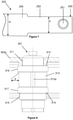
- a first embodiment of a barrel spring 2 is shown partially in picture 2 . It comprises a first portion 50 (or active part) of a first height H and a second portion 52 of a second height h lower than the first height. It also comprises at the level of the second portion, for example at the level of the inner end, a first attachment element 51 suitable for its attachment to the shaft 1 of the barrel.
- the first attachment element has a maximum height h′.
- the second portion is intended to be inserted into a groove extending circumferentially and provided on the barrel arbor. By “circumferentially extending” is meant that the groove extends at least a portion of the circumference of the shaft.
- the groove has a depth p.
- the first attachment element 51 is advantageously intended to cooperate with a second attachment element 13a provided on the shaft.
- the first attachment element may comprise a conformation 51a, 51b trapezoidal or substantially trapezoidal delimited by edges 51a, 51b.
- the two bases of the trapezoidal shape are oriented according to the height of the spring or substantially according to the height of the spring.
- the trapezoidal shape is symmetrical or substantially symmetrical.
- the second portion can be obtained by implementing a step of machining the spring at its inner end, for example by mechanical cutting, grinding, stamping, laser machining or water jet cutting.
- the spring advantageously has, before implementing this step, an elastic band of constant height H.
- a first embodiment of a barrel arbor is described below with reference to the figure 1 . It includes a groove 13 extending over a circumference of the shaft and this groove is intended to receive the barrel spring 2.
- the tree is a solid tree. On either side of the groove, it preferably comprises shoulders 12 and 14 and bearing surfaces 11 and 15.
- the cylindrical portion 11 and the cylindrical portion 15 allow rotation on the barrel arbor of the drum and of the barrel cover .
- the shoulder 12 makes it possible to stop the drum axially.
- the shoulder 14 makes it possible to stop the cover axially.
- the two shoulders ensure the movement of the casing of the barrel (cover and drum assembled) with respect to the shaft.
- the groove advantageously has a height comparable to the second height h of the spring.
- the groove comprises at least one portion whose height is less than the height of the active part of the barrel spring and the second portion 52 of the spring can be wound on the shaft in the groove.
- the section of the shaft has a shape of revolution centered on the axis of the shaft.
- the section of the shaft can also have the shape of a spiral casing, the pitch of which is equal or substantially equal to the thickness of the spring.
- the length of the second portion may correspond to the length of a complete turn wound on the shaft.
- the groove has a depth at least locally greater than or equal to the thickness of the mainspring, or even a depth greater than or equal to the thickness of the mainspring over the entire extent of the groove, or even a depth equal or substantially equal to the thickness of the barrel spring.
- the groove may extend only over part of the circumference of the shaft.
- the groove can extend over more than 180° around the axis of the barrel arbor.
- the groove may also preferably extend over the entire circumference of the barrel arbor.
- the groove bottom radius can be scalable, that is to say that the groove bottom radius at the level of a groove bottom point can have a value varying with the circumferential position of this point.
- the shaft comprises, in the groove, in particular at the bottom of the groove, a second attachment element 113a of the barrel spring, the second attachment element being intended to cooperate with the first attachment element 51 provided on the barrel spring.
- the second attachment element comprises in the case of figures 1 to 3 a recessed conformation comprising edges 13b and 13c intended to cooperate with the trapezoidal conformation 51a, 51b of the spring. Indeed, the edges 13b and 13c come into contact against the edges 51a and 51b. Due to the trapezoidal shape and depending on the angle of the edges 13b and 13c, the end of the spring may even jam on the shaft.
- the trapezoidal shapes 13a and 51 are preferably oriented circumferentially.
- the second portion 52 of the spring is preferably a non-active part, that is to say a part which does not contribute or contributes very little to the torque developed by the spring, that is to say an unstressed part or little mechanical stress in bending.
- the groove thus preferably has, at its bottom, a diameter smaller than the outer diameter of the shoulder 12 allowing the drum of the barrel to be stopped and/or smaller than the outer diameter of the shoulder 14 allowing the cover of the barrel to be stopped. .
- portions 16 and 17 are provided to receive the wound turns of the first portion (50) of the spring.
- the first and second hooking elements have been designed to reduce the bung diameter as much as possible.
- This reduction is therefore carried out by making a groove or groove on the shaft which advantageously has a height comparable to the second height h of the spring, with a clearance of diameter less than that of the shoulders necessary to hold the drum and cover.
- the inner end of the spring is cut with a lower band height over a length roughly equivalent to that of the first turn, in order to increase the number of winding turns and therefore the power reserve.
- the groove or groove is machined inside the shaft and includes a gripping part, in particular a clearance serving as a female part.
- the shape of the inner end of the spring must be adapted accordingly, by cutting out a "leg" of lower height than the rest of the blade which allows the first turn to be inserted into the groove, with a terminal part in the shape of a dovetail which acts as a male part.
- a coquillon is made, the first turn of which has an internal diameter smaller than the groove machined inside the shaft. This makes it possible to promote grip by an action of tightening the band on the shaft.
- the spring is shelled on a turn, in the particular case represented on a height reduced to 0.9 mm compared to the height of the first portion of 1.46 mm.
- This coquillon is pressed against the groove machined inside the shaft, provided with the clearance 13a for the attachment of the dovetail 51, 51a, 51b of the spring.
- the spring portion is active and its height increases to 1.46 mm.
- This solution allows first of all to greatly reduce the diameter of the bung. Compared to a standard barrel arbor for a lady's caliber (movement diameter of approximately 20 mm), the bung diameter is reduced from 1.85 mm to 1.39 mm, i.e. a reduction of 25%.
- the manufacture of the shaft is facilitated thanks to the elimination of the hook or the lug and the passage from a bung with an evolving diameter to a groove of revolution that can be machined on a lathe.
- the machining of the clearance for the grip of the end is done simply by passing an angle milling cutter (or dovetail milling cutter).
- the radial and longitudinal bearings of the cover and the drum are made as traditionally on the shaft and the assembly of the barrel within the watch movement remains traditional. More particularly, the longitudinal movement of the drum and the cover is defined by the shoulders 12 and 14 of the shaft, while the longitudinal movement of the barrel relative to the blanks also takes place by shoulders, in this case by the shoulders adjacent to the shoulders 12 and 14.
- the attachment elements also have undeniable advantages for assembling the spring on the barrel arbor.
- the radius of curvature of the inner coil of the spring before assembly is always less than the radius of the bung, so as to guarantee good pressing and tightening of the spring on the shaft and adequate fixing.
- the lower end of the spring must be opened once to cross the span and place the spring on the bung. It then takes a second manipulation to open the spring to move it away from the shaft and thus allow it to pass over the lug by sliding it downwards.
- the coquillon must be placed precisely opposite the lug to ensure good grip of the spring on the shaft.
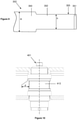
- a second embodiment of a barrel arbor according to the invention and a second embodiment of a barrel spring according to the invention are described below with reference to the figure 4 and 5 .
- the second embodiment differs from the first embodiment only by the production of the first hooking element 151 and the second hooking element, the first hooking element and the second hooking element being intended to cooperate with one another. with the other.
- a lug or hook 113a is made on the shaft at the bottom of the groove 113.
- the making of such a lug or hook is relatively complicated.
- the lug or the hook cooperates with a squab or an opening 151 made at the end 105 of the spring.
- the opening has for example a substantially rectangular shape.
- the lug or hook is shaped to be inserted into the youngster.
- the shaft pivots into a stone at its upper end.
- the drum 103a pivots on the shaft at the level of portion 111 and bearing surface 112, while cover 103b does the same on portion 115 and bearing surface 114.
- a third embodiment of a barrel arbor according to the invention and a third embodiment of a barrel spring according to the invention are described below with reference to the figure 6 and 7 .
- the third embodiment differs from the first embodiment only by the production of the first attachment element 251 and the second attachment element 213a, the first attachment element and the second attachment element being intended to cooperate with the with each other.
- a cutout 213a is made in the shaft at the bottom of the groove 213. This cutout is for example made perpendicular to the axis of the shaft.
- the cut cooperates with a pin 251 fixed to the end 205 of the spring.
- the pin may in particular be riveted to the spring.
- a fourth embodiment of a barrel arbor according to the invention and a fourth embodiment of a barrel spring according to the invention are described below with reference to the figure 8 and 9 .
- the fourth embodiment differs from the first embodiment only by the production of the first hooking element 351 and the second hooking element 313a, the first hooking element and the second hooking element being intended to cooperate with the with each other.
- a notch 313a like a radial notch, is made in the shaft at the bottom of the groove 313.
- the notch cooperates with a bend 351 made at the end 305 of the spring.
- the second hooking element comprises a protrusion, for example a hook, or a particular conformation of the groove or a recess in the groove and the first hooking element comprises an opening or a conformation particular of the inner end of the spring or a pin, in particular a riveted pin.
- the inner end of the spring forms a winding, in particular a diameter, having dimensions such that the winding is deformed when mounted on the shaft.
- the spring can be fixed to the shaft by clipping, wedging, or in the traditional way with a lug.
- the hooking is done by means of a lug (male form) cut out at the inner end of the leaf spring, which is retained by a corresponding female form machined inside the shaft.
- a lug male form
- Such a system therefore comprises an inversion of the male and female parts of the binding with respect to the standard solution: the male part is moved from the shaft onto the spring.
- the spring according to the invention can particularly be made of a material with high mechanical strength, such as for example an amorphous metal alloy described in the application WO2012010941 .
- a material with high mechanical strength such as for example an amorphous metal alloy described in the application WO2012010941 .
- traditional high performance metal alloys such as cobalt-based super-alloys (Nivaflex or other) or high nitrogen content alloys (CrMnN alloys as described in the document CH703796 ) can also be used.
- the dimensioning of the diameter of the plug must however take into account the characteristics of plastic deformation specific to the state of each material considered.
- the gain achieved by virtue of the invention may be more or less limited depending on the material chosen (and its work hardening state for polycrystalline materials). For this reason, the increase in performance observed with a barrel according to the invention will probably be more marked with a spring of the type described in the application WO2012010941 or in the document CH703796 only with a Nivaflex type spring.
- the groove diameter so that the lug 52 of the internal end of the spring makes more than one turn on the shaft.
- the active portion of the spring also comprises a part of reduced height which can be inserted into the groove of the shaft.
- each spring winding intended to be housed in these grooves has a different height.
- the heights of the windings can be smaller and smaller as one approaches the inner end of the spring.
- the shaft may have a groove 413 allowing more than one complete winding (or turn) of the spring to be accommodated therein.
- one winding or more of the spring can be housed in the groove without this winding protruding from a radial space defined by the diameter 16, 116, 216 or 316.
- the groove can be stepped.
- the groove can be seen as constituting several grooves of different heights, made one at the bottom of the other.
- This case of a stepped groove makes it possible to accommodate an extension of more than one winding of the spring in the groove without this extension of the spring protruding from a radial dimension defined by the diameter 16, 116, 216 or 316.
- the depth p of the groove is greater than the thickness of the spring.
- the barrel spring and/or the barrel arbor and/or the barrel according to the invention is particularly suitable for taking advantage of the exceptional mechanical properties of amorphous metal alloys.
- the barrel according to the invention allows a gain of two turns of development with a spring made of amorphous metallic alloy as described in the application WO2012010941 .
- the combination of the barrel according to the invention and of an amorphous metal alloy makes it possible to gain in the example above 40% of autonomy, with an identical bulk of the barrel.
- the springs were made with an identical blade length and flange.
- other factors such as flange, shell shape and blade length come into play and the system could be optimized by modifying parameters like blade length or flange characteristics.
- the maximum height h' of the first hooking element can advantageously be lower than the height H of the first portion.
- the maximum height h' of the first attachment element can also advantageously be less than the distance between the bearing surfaces 12 and 14 of the barrel arbor which define the part on which the first portion of the spring comes to rest.
- the maximum height h' of the first attachment element can advantageously be greater than the height h of the second portion of the spring, and advantageously greater than the height of groove 13 of the barrel arbor.
- the height of the spring on the first turn, including the end, can also be advantageously lower than the height of the spring on its outer part (in other words, max(h',h) ⁇ H where max(a, b) denotes the maximum value of the two parameters a, b).
- the depth p of the groove is preferably equal or substantially equal to the thickness of the spring.
- the depth of the groove can be greater than the thickness of the spring.
- the first hooking element comprises a trapezoidal or substantially trapezoidal part.
- This trapezoidal part may have a height decreasing as one moves away from the inner end of the spring.
- the trapezoidal part may have a height varying from the maximum height h′ to the height h.
- the spring is such that it meets the following condition: H > h ′ > h
- the groove intended to receive the spring has, as a second hooking element, a housing or a conformation or a recess complementary or substantially complementary to the first hooking element.
- the second height h can change along the second portion.
Landscapes
- Physics & Mathematics (AREA)
- General Physics & Mathematics (AREA)
- Engineering & Computer Science (AREA)
- Metallurgy (AREA)
- Springs (AREA)
Applications Claiming Priority (3)
| Application Number | Priority Date | Filing Date | Title |
|---|---|---|---|
| EP12002440 | 2012-04-04 | ||
| PCT/EP2013/057064 WO2013150086A1 (fr) | 2012-04-04 | 2013-04-04 | Arbre de barillet pour mouvement horloger, ressort de barillet et barillet comprenant un tel ressort et/ou un tel arbre |
| EP13713910.1A EP2834712B1 (fr) | 2012-04-04 | 2013-04-04 | Barillet comprenant un ressort de barillet et un arbre de barillet |
Related Parent Applications (1)
| Application Number | Title | Priority Date | Filing Date |
|---|---|---|---|
| EP13713910.1A Division EP2834712B1 (fr) | 2012-04-04 | 2013-04-04 | Barillet comprenant un ressort de barillet et un arbre de barillet |
Publications (1)
| Publication Number | Publication Date |
|---|---|
| EP3968093A1 true EP3968093A1 (fr) | 2022-03-16 |
Family
ID=48045552
Family Applications (2)
| Application Number | Title | Priority Date | Filing Date |
|---|---|---|---|
| EP21206061.0A Pending EP3968093A1 (fr) | 2012-04-04 | 2013-04-04 | Arbre de barillet pour mouvement horloger, ressort de barillet et barillet comprenant un tel ressort et/ou un tel arbre |
| EP13713910.1A Active EP2834712B1 (fr) | 2012-04-04 | 2013-04-04 | Barillet comprenant un ressort de barillet et un arbre de barillet |
Family Applications After (1)
| Application Number | Title | Priority Date | Filing Date |
|---|---|---|---|
| EP13713910.1A Active EP2834712B1 (fr) | 2012-04-04 | 2013-04-04 | Barillet comprenant un ressort de barillet et un arbre de barillet |
Country Status (5)
| Country | Link |
|---|---|
| US (2) | US9448533B2 (enExample) |
| EP (2) | EP3968093A1 (enExample) |
| JP (1) | JP6219925B2 (enExample) |
| CN (2) | CN108196438B (enExample) |
| WO (1) | WO2013150086A1 (enExample) |
Families Citing this family (5)
| Publication number | Priority date | Publication date | Assignee | Title |
|---|---|---|---|---|
| CN105759588A (zh) * | 2016-04-01 | 2016-07-13 | 杭州手表有限公司 | 一种长走时的高频自动机械手表 |
| JP7133909B2 (ja) * | 2016-07-04 | 2022-09-09 | ロレックス・ソシエテ・アノニム | 時計用組立体の製造方法、及び該製造方法により得られる時計用組立体 |
| CH713389B1 (fr) * | 2017-01-27 | 2020-11-30 | Richemont Int Sa | Système de liaison d'un arbre à une pièce. |
| CH714452A2 (fr) * | 2017-12-15 | 2019-06-28 | Nivarox Sa | Ressort de barillet pour un mouvement horloger d’une pièce d’horlogerie et procédé de fabrication d’un tel ressort. |
| CH716092B1 (fr) * | 2018-04-26 | 2022-10-31 | Patek Philippe Sa Geneve | Barillet d'horlogerie et procédé de modification de mouvement horloger. |
Citations (7)
| Publication number | Priority date | Publication date | Assignee | Title |
|---|---|---|---|---|
| DE612146C (de) * | 1935-10-29 | E H Jakob Kienzle Dr Ing | Zugfederbefestigung | |
| DE859698C (de) | 1938-09-01 | 1952-12-15 | Paillard Sa | Vorrichtung zur Befestigung einer Feder an einer Welle |
| CH295135A (de) | 1951-11-16 | 1953-12-15 | Ag Brac | Uhrwerk. |
| GB1148042A (en) | 1966-02-18 | 1969-04-10 | Stamford Metallics Ltd | Improvements in or relating to clockwork motors |
| CH566044A (enExample) | 1972-12-18 | 1975-08-29 | ||
| WO2012010941A1 (fr) | 2010-07-21 | 2012-01-26 | Rolex S.A. | Composant horloger comprenant un alliage métallique amorphe |
| CH703796B1 (fr) | 2010-10-28 | 2012-03-30 | Gen Ressorts Sa | Ressort. |
Family Cites Families (21)
| Publication number | Priority date | Publication date | Assignee | Title |
|---|---|---|---|---|
| US381176A (en) * | 1888-04-17 | Mainspring for watches | ||
| DE471680C (de) * | 1929-02-15 | Feinbau Maschinen Akt Ges | Federachse | |
| CH24783A (fr) * | 1901-10-29 | 1903-02-15 | Jules Jequier Fils | Barillet moteur pour montres |
| US1110061A (en) * | 1914-04-02 | 1914-09-08 | Herbert Kienzle | Removable spring-housing for clocks. |
| US1435642A (en) * | 1921-05-06 | 1922-11-14 | Waterbury Clock Co | Mainspring arbor for timepieces |
| US1628668A (en) * | 1925-12-12 | 1927-05-17 | Bell & Howell Co | Flat-spiral power spring |
| US2233075A (en) * | 1938-06-17 | 1941-02-25 | Marx & Co Louis | Spring motor |
| US2644193A (en) * | 1950-11-17 | 1953-07-07 | Axel W Anderberg | Spring sash balance |
| CH1147874A4 (enExample) * | 1974-08-22 | 1977-05-13 | ||
| CH607738B (de) * | 1975-10-21 | Ebauchesfabrik Eta Ag | Arbre de barillet extractible pour mouvement de montre. | |
| JP3757826B2 (ja) * | 2000-07-05 | 2006-03-22 | セイコーエプソン株式会社 | カード型発電機及びそれを用いた電子機器 |
| DE10357228A1 (de) * | 2003-12-08 | 2005-07-07 | Lange Uhren Gmbh | Federhausvorrichtung |
| EP1582943B1 (fr) * | 2004-04-01 | 2008-09-03 | Richemont International S.A. | Mouvement de montre comportant plusieurs barillets |
| CH702035B1 (fr) * | 2006-10-20 | 2011-04-29 | Eterna Sa Fabrique D Horlogerie | Pièce d'horlogerie. |
| EP2060957A1 (fr) * | 2007-11-16 | 2009-05-20 | ETA SA Manufacture Horlogère Suisse | Organe moteur à ressorts pour mouvement d'horlogerie |
| EP2085833A1 (fr) * | 2008-01-31 | 2009-08-05 | CT Time S.A. | Mouvement d'horlogerie modulaire |
| CH698962B1 (fr) * | 2008-06-10 | 2014-10-31 | Rolex Sa | Ressort de barillet et procédé pour sa mise en forme. |
| CH699988A2 (fr) * | 2008-11-28 | 2010-05-31 | Patek Philippe Sa Geneve | Organe moteur pour mouvement horloger. |
| CN201662690U (zh) * | 2010-03-30 | 2010-12-01 | 天津海鸥表业集团有限公司 | 一种大型机械表机芯的条轴结构 |
| EP2570862B1 (fr) * | 2011-09-15 | 2014-03-05 | ETA SA Manufacture Horlogère Suisse | Ensemble barillet d'horlogerie à diamètre de bonde réduit |
| CH706214B1 (fr) * | 2012-03-09 | 2016-09-30 | Sowind SA | Barillet de pièce d'horlogerie. |
-
2013
- 2013-04-04 US US14/390,699 patent/US9448533B2/en active Active
- 2013-04-04 WO PCT/EP2013/057064 patent/WO2013150086A1/fr not_active Ceased
- 2013-04-04 CN CN201810147446.5A patent/CN108196438B/zh active Active
- 2013-04-04 EP EP21206061.0A patent/EP3968093A1/fr active Pending
- 2013-04-04 CN CN201380018501.6A patent/CN104204965B/zh active Active
- 2013-04-04 JP JP2015503873A patent/JP6219925B2/ja active Active
- 2013-04-04 EP EP13713910.1A patent/EP2834712B1/fr active Active
-
2016
- 2016-08-08 US US15/231,303 patent/US10401796B2/en active Active
Patent Citations (7)
| Publication number | Priority date | Publication date | Assignee | Title |
|---|---|---|---|---|
| DE612146C (de) * | 1935-10-29 | E H Jakob Kienzle Dr Ing | Zugfederbefestigung | |
| DE859698C (de) | 1938-09-01 | 1952-12-15 | Paillard Sa | Vorrichtung zur Befestigung einer Feder an einer Welle |
| CH295135A (de) | 1951-11-16 | 1953-12-15 | Ag Brac | Uhrwerk. |
| GB1148042A (en) | 1966-02-18 | 1969-04-10 | Stamford Metallics Ltd | Improvements in or relating to clockwork motors |
| CH566044A (enExample) | 1972-12-18 | 1975-08-29 | ||
| WO2012010941A1 (fr) | 2010-07-21 | 2012-01-26 | Rolex S.A. | Composant horloger comprenant un alliage métallique amorphe |
| CH703796B1 (fr) | 2010-10-28 | 2012-03-30 | Gen Ressorts Sa | Ressort. |
Also Published As
| Publication number | Publication date |
|---|---|
| WO2013150086A1 (fr) | 2013-10-10 |
| EP2834712B1 (fr) | 2021-11-24 |
| JP6219925B2 (ja) | 2017-10-25 |
| CN104204965B (zh) | 2018-03-27 |
| CN104204965A (zh) | 2014-12-10 |
| US9448533B2 (en) | 2016-09-20 |
| CN108196438A (zh) | 2018-06-22 |
| US20150092523A1 (en) | 2015-04-02 |
| EP2834712A1 (fr) | 2015-02-11 |
| US10401796B2 (en) | 2019-09-03 |
| CN108196438B (zh) | 2020-09-08 |
| JP2015512519A (ja) | 2015-04-27 |
| US20160349703A1 (en) | 2016-12-01 |
Similar Documents
| Publication | Publication Date | Title |
|---|---|---|
| EP2657794B1 (fr) | Arbre et ressort de barillet | |
| EP2350745B1 (fr) | Organe moteur pour mouvement horloger | |
| EP2834712B1 (fr) | Barillet comprenant un ressort de barillet et un arbre de barillet | |
| EP2437125B1 (fr) | Pièce d'horlogerie | |
| EP3252542B1 (fr) | Pièce de fixation d'un ressort-spiral horloger | |
| EP3361324A1 (fr) | Système de cliquet horloger | |
| EP3070537A1 (fr) | Base de temps comportant un echappement a impulsion directe et a force constante | |
| EP3220206B1 (fr) | Dispositif horloger de transmission | |
| EP2107433B1 (fr) | Procédé d'assemblage d'une pièce sur un axe | |
| EP4016195B1 (fr) | Tourbillon pour mouvement horloger | |
| CH713409B1 (fr) | Balancier pour balancier-spiral du type thermocompensé, balancier-spiral du type thermocompensé, mouvement et pièce d'horlogerie. | |
| CH715052A2 (fr) | Mécanisme à couple constant, mouvement de pièce d'horlogerie, et pièce d'horlogerie. | |
| CH698675B1 (fr) | Palier amortisseur de chocs pour pièce d'horlogerie. | |
| EP3218770B1 (fr) | Organe moteur pour mouvement d'horlogerie | |
| EP3598241B1 (fr) | Mecanisme horloger a dispositif a force constante | |
| EP2869134B1 (fr) | Système de barillet pour pièce d'horlogerie | |
| EP3252541A1 (fr) | Pièce de fixation d'un ressort-spiral horloger | |
| EP4194966B1 (fr) | Verrou destiné à limiter le débattement axial d'un mobile d'un mouvement horloger et mouvement horloger le comportant | |
| EP3872576B1 (fr) | Barillet d'horlogerie a arbre vrille | |
| EP3432082A1 (fr) | Organe reglant | |
| WO2013104941A1 (fr) | Piece d'horlogerie a remontage automatique | |
| EP2264550A1 (fr) | Roue pour dispositif inverseur, procédé de fabrication d'une telle roue, et dispositifs inverseurs pour mouvement horloger comportant une telle roue | |
| CH701968B1 (fr) | Source d'énergie pour sonnerie et pièce d'horlogerie munie d'une telle source d'énergie. | |
| EP4325303A1 (fr) | Mécanisme de quantième perpétuel à cames concentriques | |
| CH716092B1 (fr) | Barillet d'horlogerie et procédé de modification de mouvement horloger. |
Legal Events
| Date | Code | Title | Description |
|---|---|---|---|
| PUAI | Public reference made under article 153(3) epc to a published international application that has entered the european phase |
Free format text: ORIGINAL CODE: 0009012 |
|
| STAA | Information on the status of an ep patent application or granted ep patent |
Free format text: STATUS: THE APPLICATION HAS BEEN PUBLISHED |
|
| AC | Divisional application: reference to earlier application |
Ref document number: 2834712 Country of ref document: EP Kind code of ref document: P |
|
| AK | Designated contracting states |
Kind code of ref document: A1 Designated state(s): AL AT BE BG CH CY CZ DE DK EE ES FI FR GB GR HR HU IE IS IT LI LT LU LV MC MK MT NL NO PL PT RO RS SE SI SK SM TR |
|
| STAA | Information on the status of an ep patent application or granted ep patent |
Free format text: STATUS: REQUEST FOR EXAMINATION WAS MADE |
|
| 17P | Request for examination filed |
Effective date: 20220916 |
|
| RBV | Designated contracting states (corrected) |
Designated state(s): AL AT BE BG CH CY CZ DE DK EE ES FI FR GB GR HR HU IE IS IT LI LT LU LV MC MK MT NL NO PL PT RO RS SE SI SK SM TR |
|
| P01 | Opt-out of the competence of the unified patent court (upc) registered |
Effective date: 20230530 |
|
| STAA | Information on the status of an ep patent application or granted ep patent |
Free format text: STATUS: EXAMINATION IS IN PROGRESS |
|
| 17Q | First examination report despatched |
Effective date: 20240719 |