EP3967532A1 - Faltverdeck für ein cabriolet-fahrzeug - Google Patents
Faltverdeck für ein cabriolet-fahrzeug Download PDFInfo
- Publication number
- EP3967532A1 EP3967532A1 EP21196030.7A EP21196030A EP3967532A1 EP 3967532 A1 EP3967532 A1 EP 3967532A1 EP 21196030 A EP21196030 A EP 21196030A EP 3967532 A1 EP3967532 A1 EP 3967532A1
- Authority
- EP
- European Patent Office
- Prior art keywords
- rear window
- clamping bracket
- area
- edge
- folding top
- Prior art date
- Legal status (The legal status is an assumption and is not a legal conclusion. Google has not performed a legal analysis and makes no representation as to the accuracy of the status listed.)
- Granted
Links
- 229920003023 plastic Polymers 0.000 claims abstract description 6
- 239000004033 plastic Substances 0.000 claims abstract description 6
- 238000005538 encapsulation Methods 0.000 claims description 14
- 229920005830 Polyurethane Foam Polymers 0.000 claims description 11
- 238000007789 sealing Methods 0.000 claims description 11
- 229910052751 metal Inorganic materials 0.000 claims description 8
- 239000002184 metal Substances 0.000 claims description 8
- 239000006260 foam Substances 0.000 claims description 2
- 230000002093 peripheral effect Effects 0.000 claims 2
- 238000005187 foaming Methods 0.000 abstract description 2
- 239000004814 polyurethane Substances 0.000 description 15
- 239000004744 fabric Substances 0.000 description 3
- 229910052782 aluminium Inorganic materials 0.000 description 2
- XAGFODPZIPBFFR-UHFFFAOYSA-N aluminium Chemical compound [Al] XAGFODPZIPBFFR-UHFFFAOYSA-N 0.000 description 2
- 239000011324 bead Substances 0.000 description 2
- 210000002414 leg Anatomy 0.000 description 2
- 239000000463 material Substances 0.000 description 2
- 230000000007 visual effect Effects 0.000 description 2
- 229910000838 Al alloy Inorganic materials 0.000 description 1
- 229910000831 Steel Inorganic materials 0.000 description 1
- 239000011248 coating agent Substances 0.000 description 1
- 238000000576 coating method Methods 0.000 description 1
- 238000004519 manufacturing process Methods 0.000 description 1
- 229920002635 polyurethane Polymers 0.000 description 1
- 239000011496 polyurethane foam Substances 0.000 description 1
- 239000011347 resin Substances 0.000 description 1
- 229920005989 resin Polymers 0.000 description 1
- 238000007493 shaping process Methods 0.000 description 1
- 230000006641 stabilisation Effects 0.000 description 1
- 238000011105 stabilization Methods 0.000 description 1
- 230000000087 stabilizing effect Effects 0.000 description 1
- 239000010959 steel Substances 0.000 description 1
- 230000007704 transition Effects 0.000 description 1
- 210000000689 upper leg Anatomy 0.000 description 1
Images


Classifications
-
- B—PERFORMING OPERATIONS; TRANSPORTING
- B60—VEHICLES IN GENERAL
- B60J—WINDOWS, WINDSCREENS, NON-FIXED ROOFS, DOORS, OR SIMILAR DEVICES FOR VEHICLES; REMOVABLE EXTERNAL PROTECTIVE COVERINGS SPECIALLY ADAPTED FOR VEHICLES
- B60J7/00—Non-fixed roofs; Roofs with movable panels, e.g. rotary sunroofs
- B60J7/08—Non-fixed roofs; Roofs with movable panels, e.g. rotary sunroofs of non-sliding type, i.e. movable or removable roofs or panels, e.g. let-down tops or roofs capable of being easily detached or of assuming a collapsed or inoperative position
- B60J7/12—Non-fixed roofs; Roofs with movable panels, e.g. rotary sunroofs of non-sliding type, i.e. movable or removable roofs or panels, e.g. let-down tops or roofs capable of being easily detached or of assuming a collapsed or inoperative position foldable; Tensioning mechanisms therefor, e.g. struts
- B60J7/1226—Soft tops for convertible vehicles
- B60J7/1234—Soft tops for convertible vehicles characterised by arches, e.g. shape or material
- B60J7/1247—Tensioning bow at rear of soft top
-
- B—PERFORMING OPERATIONS; TRANSPORTING
- B60—VEHICLES IN GENERAL
- B60J—WINDOWS, WINDSCREENS, NON-FIXED ROOFS, DOORS, OR SIMILAR DEVICES FOR VEHICLES; REMOVABLE EXTERNAL PROTECTIVE COVERINGS SPECIALLY ADAPTED FOR VEHICLES
- B60J1/00—Windows; Windscreens; Accessories therefor
- B60J1/18—Windows; Windscreens; Accessories therefor arranged at the vehicle rear
- B60J1/1807—Windows; Windscreens; Accessories therefor arranged at the vehicle rear movable for vehicles with convertible top
- B60J1/1815—Windows; Windscreens; Accessories therefor arranged at the vehicle rear movable for vehicles with convertible top non-adjustably mounted in and moving with the soft-top cover
-
- B—PERFORMING OPERATIONS; TRANSPORTING
- B60—VEHICLES IN GENERAL
- B60J—WINDOWS, WINDSCREENS, NON-FIXED ROOFS, DOORS, OR SIMILAR DEVICES FOR VEHICLES; REMOVABLE EXTERNAL PROTECTIVE COVERINGS SPECIALLY ADAPTED FOR VEHICLES
- B60J7/00—Non-fixed roofs; Roofs with movable panels, e.g. rotary sunroofs
- B60J7/08—Non-fixed roofs; Roofs with movable panels, e.g. rotary sunroofs of non-sliding type, i.e. movable or removable roofs or panels, e.g. let-down tops or roofs capable of being easily detached or of assuming a collapsed or inoperative position
- B60J7/12—Non-fixed roofs; Roofs with movable panels, e.g. rotary sunroofs of non-sliding type, i.e. movable or removable roofs or panels, e.g. let-down tops or roofs capable of being easily detached or of assuming a collapsed or inoperative position foldable; Tensioning mechanisms therefor, e.g. struts
- B60J7/1226—Soft tops for convertible vehicles
- B60J7/123—Soft tops for convertible vehicles characterised by means for fastening the soft top cloth to the arches or vehicle body work
Definitions
- the invention relates to a folding top for a convertible vehicle with a top cover and a rear window foamed into the top cover with a plastic, with the foam covering between the vehicle top and the rear window along the entire edge of the rear window.
- Top for vehicles that can be opened have a top layer that is generally flexible.
- a motor vehicle top comprising a top layer with at least one recess, within which a rear window is arranged, with an edge area of the top layer surrounding the recess being connected to the outer edge area of the rear window using a PUR bead element.
- connection area between the top layer and the rear window is designed in such a way that a polyurethane bead element connects the edge area of the top layer to the outer edge area of the rear rail and at the same time at least partially overlaps an electrical busbar.
- a polyurethane bead element connects the edge area of the top layer to the outer edge area of the rear rail and at the same time at least partially overlaps an electrical busbar.
- Such a folding top is also from DE 20 2006 017 746 U1 famous.
- This folding top also includes a foldable top layer, which can be adjusted by means of a top linkage between a closed position covering a vehicle interior and an open position releasing it.
- the top layer In a section located in the closed position in the rear area, the top layer has a recess, within which a rear window is arranged.
- the rear window or a rear window frame is connected to the top layer all the way round via a cast resin profile.
- the soft top cover runs further below the lower edge of the rear window and forms the end of the folding top by folding over the tension bracket profile.
- the object is achieved with a folding top for a convertible vehicle with a top cover and a rear window foamed into the top cover with a plastic, the foaming between the vehicle top and the rear window taking place along the entire edge of the rear window, and with a clamping bracket, at least in the lower Area of the edge of the rear window of the top cover to the rear window has an inward offset in the direction of the vehicle interior.
- the invention makes it possible to construct a rear window that is foamed into the top cover along the entire edge in such a way that the joint with the bottom edge of the rear window forms a clean finish with the top compartment lid or trunk lid.
- the rear window is attached to the soft top cover all around with PU foam.
- the visual impression that the soft top cover is only connected to the rear window on three sides (top, side left and right) and the lower edge of the rear window forms the end is created by the fact that the under the rear window and the lower edge of the rear window is offset inwards, foamed-in top cover, is led out below the PU edge, which is sprayed on at the lower end of the rear window as a closure, and is covered by the PU edge, which serves as the closure of the rear window, so that the PU edge visually forms the rear window closure and not the convertible top cover running underneath.
- the rear window is firmly connected to the clamping bracket, this ensures that no relative movement can take place between the rear window and the clamping bracket during an adjustment movement of the folding top between a closed position and an open position.
- sheet metal inserts with a thread are advantageously molded into the PU foam coating of the rear window, with the help of which the rear window is firmly screwed to the circumferential or U-shaped clamping bracket or to components connected to the clamping bracket.
- a connecting strut is arranged laterally as a component for connecting the rear window to the clamping bracket.
- the connecting struts are fixed to the rear window via their first end area and to the clamping bracket via their second end area.
- the x, y and z directions designate the usual directions in a vehicle coordinate system, the x direction being the longitudinal direction of the vehicle, the y direction being the transverse direction of the vehicle and the z direction being the vertical direction of the vehicle.
- Y0 denotes the vehicle center in the vehicle lateral direction.
- the folding top 1 shows a folding top 1 of a convertible vehicle in a perspective view obliquely from behind.
- the folding top 1 comprises a top cover 4 or top material, which can be adjusted by means of a top linkage between a closed position covering a vehicle interior and an open position releasing it.
- the adjustable folding top 1 extends, starting from a windshield frame (not shown) arranged on the front side V, into the rear area H of the vehicle.
- the folding top 1 is constructed symmetrically in relation to a central axis A.
- the rear area H of the folding top 1 is designed to point obliquely downwards, being delimited by a clamping bracket 3 in its lower end area.
- the tension bracket 3 rests on an upper edge O of the body or of the convertible top compartment cover 12 .
- the essentially circumferential edge R of the folding top 1 here forms the contact area with the vehicle body and is sealed by sealing elements 10 .
- FIG 1 shows the folding top 1 in the closed position. It can be seen from the illustration that the top cover 4 has a cutout in the obliquely running rear area, in which a rear window 6 is arranged.
- the rear window 6 comprises a lower edge area 6a, an upper edge area 6b and lateral edge areas e 6c.
- the Rear window 6 circumferentially, ie attached along the entire edge with all edge regions 6a, 6b, 6c to the top cover by a profile-like PU encapsulation 8.
- the tension bracket 3 is pressed via a storm rod into the position tensioning the top cloth 4 and is fixed in this position.
- the tension bracket 3 has an essentially U-shaped form and has a central section 3a running in the transverse direction and lateral legs 3b, the shape corresponding to the desired course of the top cover 4 in the lateral and rear area.
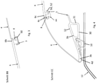
- FIG 2 shows the clamping bracket 3, which is wedge-shaped in section and is designed as a hollow profile.
- the clamping bracket comprises an underside 30, a side area 31 running vertically and an upper side 32 running obliquely towards the rear side H downwards.
- a receiving section B, a connecting section A and a fastening section C are formed adjacent to the hollow profile.
- the receiving section B is designed as a channel-shaped groove which is open at the bottom and has an opening area which is narrowed in cross-section.
- the clamping bracket 3 is designed with the connecting section 36 , which comprises a web-like strip 37 with a thickened end region 38 on the underside opposite the upper side 32 .
- the connecting section C is formed in the side area 31 and is used for screwing 44 the rear window 6 to the clamping bracket 3.
- the PU encapsulation 8 is designed in this area with a sheet metal insert with a thread.
- the hollow profile with receiving section B, fastening section C and connecting section A/36 is designed in one piece.
- the clamp 3 can be made of metal, preferably light metal, more preferably aluminum or an aluminum alloy. However, it is also conceivable that the clamping bracket is made of plastic. Aluminum offers the advantage that it is significantly lighter than steel and is the preferred choice for the production of extruded profiles.
- the figures 2 , 3 and 4 show sections at different positions of the rear window 6 with connection to the top cover 4 and the clamping bracket 3.
- the figure 2 shows the connection and arrangement of the rear window 6 on the top cover 4 in the area of the lower edge 6a of the rear window 6.
- This lower edge 6a has the profile-like PU foam encapsulation 8 as a closure at the edge.
- the top cover 4 is foamed into the profile-like PU encapsulation 8 by means of a first edge area 4a and folded inward around an edge 14 of the PU encapsulation 8 pointing downwards towards the top compartment cover 12 and fixed to the clamping bracket 3 by means of a second edge area 4b.
- This second edge area 4b at the end of the top cover 4 is guided onto the underside 30 of the clamping bracket 3 and is connected to the strip 37 there.
- the connection is made via a retaining strip 41 fastened to the top cover 4 and having a receptacle 42 (keder connection).
- the top cover 4 is pressed onto the strip 37 with the thickened end area 38 via the receptacle 42 and is held in a form-fitting manner on the connecting section 36 .
- the top cover 4 is therefore offset inwards towards the vehicle interior I in relation to the rear window 6 in the lower edge area 6a and is not visible to a user in the area of the lower edge area 6a when viewed from the outside A.
- the rear window 6 rests by means of its lower edge area 6a on the upper side 32 of the clamping bracket 3 in its central area 3a seen from above and completely covers the clamping bracket 3 in this area.
- This lower edge area 6a of the rear window 6 includes a blackened area 16.
- the clamping bracket 3 and the fastenings of the clamping bracket 3 by means of screw connections 44 are therefore likewise not visible to a user from the outside.
- the folding top 1 rests with a top edge region R on the top compartment lid via the sealing element 10 on the edge.
- the sealing element 10 is a basic body made of a rubber-elastic hollow profile 46 with a holding strip with a head section 48 projecting upwards.
- the head section 48 has holding sections that run obliquely outwards.
- the head section 48 of the sealing element 10 is pressed into the receiving section B, with the holding sections being supported in the receiving section B. FIG. In this way, the connection of the sealing element 10 to the clamp 3 is achieved.
- the figure 3 shows in section the connection and arrangement of the rear window 6 on the top cover 4 in the area of the upper edge 6b of the rear window 6.
- This upper edge 6b has the profile-like PU foam encapsulation 8 on the edge.
- the top cover 4 is kept foamed by means of an edge area in the profile-like PU encapsulation 8 .
- a U-shaped frame element 50 is arranged in the area of the upper edge, which receives the rear window 6 with PU foam 8 in this area.
- the frame element 50 is guided along the upper edge 6b to the lateral edges 6c and is connected to the clamping bracket 3 via lateral connecting struts 52 and is held there.
- the figure 4 shows in section the connection and arrangement of the rear window 6 on the top cover 4 in the area of the lateral edges 6c of the rear window 6.
- This lateral edge 6b has the profile-like PU foam 8 with foamed sheet metal insert and thread on the edge.
- the top cover 4 is held foamed into the profile-like PU foam encapsulation 8 by means of a first edge area 4c and, starting from the side area, is guided obliquely laterally downwards to the lateral leg 3b of the clamping bracket 3 and folded inwards around the connecting section 36 and attached to the underside 30 of the Clamping bracket 3 is fixed to the fastening section A via the bar with the end section 38 .
- the fixed connection of the rear window 6 to the clamping bracket 3 takes place via the lateral connecting struts 52 which are fixed via a screw connection 44 on the foamed sheet metal insert with a thread.
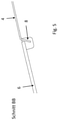
- no frame element 50 for stabilizing and supporting the rear window 6 on the clamping bracket 3 is provided in the upper edge region 6b.
- top cover 4 is only connected to the rear window 6 on three sides at the upper edge area 6b and the side edge areas 6c (top, left and right side) and the lower edge area 6a of the rear window 6 forms the end that the foamed top cover 4, which is offset inwards under the rear window and towards the lower edge of the rear window 6, is led out below the PU edge, which is injection-molded at the lower end of the rear window 6 as a conclusion, and through the PU edge, which as a conclusion used for the rear window 6, is covered so that the PU edge visually forms the end of the rear window and not the convertible top cover 4 running underneath.
- the clamping bracket frame accommodates the sealing element 10 which forms the seal between the clamping bracket 3 and the folding-top compartment cover 12 as in a conventional clamping bracket top.
- the convertible top cover 4 is guided around the rear edge of the clamping bracket 3, as well as in the area of the lower edge of the rear window, around the PU encapsulation and is attached to the clamping bracket 3 in front of the sealing element 10 with a sewn-on plastic piping.
Landscapes
- Engineering & Computer Science (AREA)
- Mechanical Engineering (AREA)
- Seal Device For Vehicle (AREA)
- Body Structure For Vehicles (AREA)
Abstract
Description
- Die Erfindung betrifft ein Faltverdeck für ein Cabriolet-Fahrzeug mit einem Verdeckbezug und einer in den Verdeckbezug mit einem Kunststoff eingeschäumten Heckscheibe, wobei die Umschäumung zwischen Fahrzeugverdeck und Heckscheibe entlang des gesamten Randes der Heckscheibe erfolgt.
- Verdecke für Fahrzeuge zum Öffnen weisen eine Verdeckschicht auf, die in der Regel flexibel ausgebildet ist. Man spricht hier auch von Soft-Top- oder Cabriolet-Verdecken.
- Aus der
DE10 2013 010 883 A1 ist ein Kraftfahrzeugverdeck bekannt, umfassend eine Verdeckschicht mit wenigstens einer Aussparung, innerhalb der eine Heckscheibe angeordnet ist, wobei ein die Aussparung umgebender Randbereich der Verdeckschicht mit dem äußeren Randbereich der Heckscheibe unter Verwendung eines PUR-Wulstelementes verbunden ist. - Der Verbindungsbereich zwischen Verdeckschicht und Heckscheibe wird derartig ausgestaltet, dass ein Polyurethan-Wulstelement den Randbereich der Verdeckschicht mit dem äußeren Randbereich der Heckschiene verbindet, und zugleich eine elektrische Sammelschiene zumindest teilweise übergreift. Die Verwendung von Polyurethanschaum zur Herstellung der Einfassung von Fahrzeugscheiben ist bekannt.
- Ein derartiges Faltverdeck ist auch aus der
DE 20 2006 017 746 U1 bekannt. Dieses Faltverdeck umfasst ebenfalls eine faltbare Verdeckschicht, die mittels eines Verdeckgestänges zwischen einer einen Fahrzeuginnenraum überdeckenden Schließstellung und einer diesen freigebenden Öffnungsstellung verstellbar ist. Die Verdeckschicht weist in einem in Schließstellung im Heckbereich befindlichen Abschnitt eine Aussparung auf, innerhalb der eine Heckscheibe angeordnet ist. Die Heckscheibe bzw. ein Heckscheibenrahmen ist umlaufend über eine Gießharzprofil an der Verdeckschicht angebunden. - Verbaut man diese Fahrzeugscheiben in einer festen Karosserie, sind die umschäumten Randbereiche verdeckt und stellen kein Problem dar. Verwendet man eine solche Fahrzeugscheibe als Heckscheibe in einem Faltverdeck wird die Heckscheibe komplett mit dem Verdeckbezug als Verdeckschicht mit umschäumten Randbereichen, hergestellt.
- Bei diesen standardmäßig im Verdeckbezug eingebundenen Cabrio-Heckscheiben verläuft der Verdeckbezug unterhalb der Unterkante der Heckscheibe weiter in Verlängerung und bildet durch Umschlagen über das Spannbügelprofil den Abschluss des Faltverdecks.
- Gerade im unteren Randbereich der Heckscheibe stellt das aber ein ästhetisches Problem dar, da nur wenig Verdeckbezug sichtbar wird. Des Weiteren muss in diesem Bereich eine durchgehende Dichtlinie auch in den seitlichen Randbereichen gewährleistet sein.
- Es ist Aufgabe der Erfindung ein Faltverdeck mit einer Heckscheibe vorzuschlagen, das den unteren Randbereich der Heckscheibe mit dem Verdeckmaterial in einem sauberen Fugenabschluss ermöglicht, wobei eine sichere Abdichtung gewährleistet werden soll.
- Diese Aufgabe wird durch die im Anspruch 1 angegebenen Merkmale gelöst.
- Die Aufgabe wird gelöst mit einem Faltverdeck für ein Cabriolet-Fahrzeug mit einem Verdeckbezug und einer in den Verdeckbezug mit einem Kunststoff eingeschäumten Heckscheibe, wobei die Umschäumung zwischen Fahrzeugverdeck und Heckscheibe entlang des gesamten Randes der Heckscheibe erfolgt, und mit einem Spannbügel, wobei zumindest im unteren Bereich des Randes der Heckscheibe der Verdeckbezug zur Heckscheibe einen Versatz nach innen in Richtung Fahrzeuginnenraum aufweist.
- Die Erfindung ermöglicht es, eine im Verdeckbezug entlang des gesamten Randes eingeschäumte Heckscheibe so aufzubauen, dass optisch mit der Unterkante der Heckscheibe die Fuge zum Verdeckkastendeckel bzw. Kofferraumdeckel einen sauberen Abschluss bildet.
- Durch den umlaufend um die Heckscheibe eingeschäumten Verdeckbezug, entsteht keine Unterbrechung der Dichtlinie zwischen Verdeckbezug und Heckscheibe, vor allem im bisher schwierigen Übergangsbereich, seitlich entlang der Heckscheibe nach innen zum Fahrzeuginnenraum, sowie nach außen entlang des Spannbügels Richtung C-Säule.
- Die Heckscheibe ist ringsum mit dem Verdeckbezug durch eine PU-Umschäumung befestigt. Der optische Eindruck, dass der Verdeckbezug nur an drei Seiten mit der Heckscheibe verbunden ist (oben, seitlich links und rechts) und die Unterkante der Heckscheibe den Abschluss bildet, entsteht dadurch, dass der unter der Heckscheibe und zur Unterkante der Heckscheibe nach innen versetzte, eingeschäumte Verdeckbezug, unterhalb des PU-Randes, welcher am unter Ende der Heckscheibe als Abschluss angespritzt ist, herausgeführt wird und durch den PU-Rand, der als Abschluss der Heckscheibe dient, abgedeckt wird, so dass der PU-Rand optisch den Heckscheibenabschluss bildet und nicht der darunter verlaufende Verdeckbezug.
- Die Heckscheibe ist mit dem Spannbügel fest verbunden, hierdurch ist gewährleistet, dass bei einer Verstellbewegung des Faltverdecks zwischen einer Schließstellung und Öffnungsstellung keine Relativbewegung zwischen Heckscheibe und Spannbügel erfolgen kann.
- Zur sicheren Anbindung der Heckscheibe an den Spannbügel werden vorteilhafterweise Blecheinleger mit Gewinde in der PU-Umschäumung der Heckscheibe umspritzt, mit deren Hilfe, die Heckscheibe mit dem umlaufenden oder U-förmigen Spannbügel bzw. mit an dem Spannbügel verbundenen Bauteilen fest verschraubt wird.
- Vorteilhafterweise sind zur Anbindung der Heckscheibe an dem Spannbügel seitlich als Bauteile jeweils eine Anbindungsstrebe angeordnet. Die Anbindungsstreben sind über ihren ersten Endbereich an der Heckscheibe und über ihren zweiten Endbereich an dem Spannbügel festgelegt.
- Die x, y und z Richtung bezeichnen die in einem Fahrzeugkoordinatensystem üblichen Richtungen, wobei die X-Richtung die Fahrzeuglängsrichtung, die y-Richtung die Fahrzeugquerrichtung und die z-Richtung die Fahrzeughochrichtung ist. Mit Y0 wird in der Fahrzeugquerrichtung die Fahrzeugmitte bezeichnet.
- Das erfindungsgemäße Faltverdeck wird in unterschiedlichen Ausführungsformen nachfolgend näher beschrieben und in den Zeichnungen schematisch dargestellt.
- Es zeigt:
-
Figur 1 eine perspektivische Darstellung eines erfindungsgemäßen Faltverdecks mit Heckscheibe in der Schließstellung, -
Figur 2 einen Schnitt entlang A-A bei Y0, -
Figur 3 einen Schnitt entlang B-B gemäß einer ersten Ausführungsform, -
Figur 4 einen Schnitt entlang C-C im Bereich der Anbindung der Heckscheibe an den Spannbügel im seitlichen Randbereich; und -
Figur 5 einen Schnitt entlang B-B in einer alternativen Ausführungsform. -
Fig. 1 zeigt in einer perspektivischen Ansicht von schräg hinten ein Faltverdeck 1 eines Cabriolet-Fahrzeugs. Das Faltverdeck 1 umfasst einen Verdeckbezug 4 bzw. Verdeckstoff, der mittels eines Verdeckgestänges zwischen einer einen Fahrzeuginnenraum überdeckenden Schließstellung und einer diesen freigebenden Öffnungsstellung verstellt werden kann. Das verstellbare Faltverdeck 1 erstreckt sich ausgehend von einem auf der Vorderseite V angeordneten nicht dargestellten Windschutzscheibenrahmen in den Heckbereich H des Fahrzeugs. Das Faltverdeck 1 ist bezogen auf eine Mittelachse A symmetrisch aufgebaut. - Der entgegen der Fahrtrichtung weisende Heckbereich H des Faltverdecks 1 ist schräg nach unten weisend ausgebildet, wobei er in seinem unteren Endbereich durch einen Spannbügel 3 begrenzt wird. Der Spannbügel 3 liegt dabei auf einer Oberkante O der Karosserie bzw. des Verdeckkastendeckels 12 an. Der im Wesentlichen umlaufende Rand R des Faltverdecks 1 bildet hierbei den Auflagebereich zur Fahrzeugkarosserie und ist über Dichtungselemente 10 abgedichtet.
-
Figur 1 zeigt das Faltverdeck 1 in der Schließstellung. Aus der Darstellung kann man ersehen, dass der Verdeckbezug 4 im schräg verlaufenden heckseitigen Bereich einen Ausschnitt aufweist, in dem eine Heckscheibe 6 angeordnet ist. Die Heckscheibe 6 umfasst dabei einen unteren Randbereich 6a, einen oberen Randbereich 6b, sowie seitliche Randbereich e 6c. Zur unlösbaren Anbindung des Verdeckbezugs 4 an die Heckscheibe 6 ist die Heckscheibe 6 umlaufend, d.h. entlang des gesamten Rands mit allen Randbereichen 6a, 6b, 6c mit dem Verdeckbezug durch ein profilartige PU-Umschäumung 8 befestigt. - In die profilartige PU-Umschäumung 8 der Heckscheibe 6 werden Blecheinleger mit Gewinde umspritzt, mit deren Hilfe, die Heckscheibe 6 mit dem umlaufenden oder U-förmigen Spannbügel 3 fest verschraubt wird. Dadurch erfolgt keine Relativbewegung zwischen Heckscheibe 6 und Spannbügel 3 während der Verstellbewegung des Faltverdecks zwischen den unterschiedlichen Stellungen. Der Spannbügel 3 hält die Heckscheibe 6 fest in Position.
- Zur Erzeugung der Stoffspannung in der Schließposition und zur Erzielung der notwendigen Formgebung wird der Spannbügel 3 über eine Sturmstange in die den Verdeckbezug 4 spannende Position gedrückt und in dieser Position fixiert. Der Spannbügel 3 weist eine im Wesentlichen u-förmige Form auf, und weist einen mittleren in Querrichtung verlaufenden Abschnitt 3a und seitliche Schenkel 3b auf, wobei die Form dem gewünschten Verlauf des Verdeckbezugs 4 im seitlichen und hinteren Bereich entspricht.
-
Figur 2 zeigt den im Schnitt keilförmigen Spannbügel 3, der als Hohlprofil ausgeführt ist. Der Spannbügel umfasst dabei eine Unterseite 30, einen senkrecht verlaufenden Seitenbereich 31 und einen schräg zur Heckseite H nach unten verlaufende Oberseite 32 auf. - Im Bereich der Unterseite 30 des Spannbügels 3 sind benachbart zum Hohlprofil ein Aufnahmeabschnitt B ein Verbindungsabschnitt A und ein Befestigungsabschnitt C ausgebildet. Der Aufnahmeabschnitt B ist als kanalförmige nach unten offene Nut ausgeführt, die einen im Querschnitt verengten Öffnungsbereich aufweist. Des Weiteren ist der Spannbügel 3 mit dem Verbindungsabschnitt 36 ausgeführt, der auf der zur Oberseite 32 gegenüberliegenden Unterseite eine stegartige Leiste 37 mit verdicktem Endbereich 38 umfasst. Der Verbindungsabschnitt C ist im Seitenbereich 31 angeformt und dient der Verschraubung 44 der Heckscheibe 6 an dem Spannbügel 3. Die PU Umschäumung 8 ist in diesem Bereich mit einem Blecheinleger mit Gewinde ausgeführt.
- Das Hohlprofil mit Aufnahmeabschnitt B, Befestigungsabschnitt C und Verbindungsabschnitt A/36 ist einstückig ausgebildet.
- Der Spannbügel 3 kann aus Metall bevorzugt aus Leichtmetall, weiter bevorzugt aus Aluminium oder einer Aluminiumlegierung, hergestellt werden. Es ist jedoch auch denkbar, dass der Spannbügel aus Kunststoff hergestellt, wird. Aluminium bietet den Vorteil, dass es wesentlich leichter als Stahl ist, und wird bevorzugt zur Herstellung von Strangpressprofilen eingesetzt.
- Die
Figuren 2 ,3 und 4 zeigen dabei Schnitte an unterschiedlichen Positionen der Heckscheibe 6 mit Anbindung an den Verdeckbezug 4 und den Spannbügel 3. - Die
Figur 2 zeigt dabei die Anbindung und Anordnung der Heckscheibe 6 an dem Verdeckbezug 4 im Bereich der unteren Randkante 6a der Heckscheibe 6. Diese untere Randkante 6a weist als Abschluss randseitig die profilartige PU Umschäumung 8 auf. Der Verdeckbezug 4 ist dabei mittels eines ersten Randbereichs 4a in der profilartigen PU Umschäumung 8 eingeschäumt gehalten und um eine nach unten zum Verdeckkastendeckel 12 weisende Randkante 14 der PU Umschäumung 8 nach innen umgeschlagen und mittels eines zweiten Randbereichs 4b am Spannbügel 3 fixiert. - Dieser zweite endseitige Randbereich 4b des Verdeckbezugs 4 ist auf die Unterseite 30 des Spannbügels 3 geführt und dort an der Leiste 37 angebunden. Die Anbindung erfolgt über eine an dem Verdeckbezug 4 befestigte Halteleiste 41, die eine Aufnahme 42 aufweist (Kederanbindung). Der Verdeckbezug 4 ist über die Aufnahme 42 auf die Leiste 37 mit verdicktem Endbereich 38 aufgepresst und wird an dem Verbindungsabschnitt 36 formschlüssig gehalten. Der Verdeckbezug 4 weist somit in Bezug auf die Heckscheibe 6 im unteren Randbereich 6a einen Versatz nach innen in Richtung Fahrzeuginnenraum I auf und ist im Bereich des unteren Randbereichs 6a von der Außenseite A her gesehen für einen Nutzer nicht sichtbar.
- Wie es aus der Darstellung der
Figur 2 zu erkennen ist, liegt die Heckscheibe 6 mittels ihres unteren Randbereichs 6a auf der Oberseite 32 des Spannbügels 3 in seinem mittleren Bereich 3a von oben her gesehen auf und überdeckt den Spannbügel 3 in diesem Bereich vollständig. Dieser untere Randbereich 6a der Heckscheibe 6 umfasst einen geschwärzten Bereich 16. Somit sind der Spannbügel 3 und die Befestigungen des Spannbügels 3 mittels Verschraubung 44 von außen für einen Nutzer ebenfalls nicht sichtbar. - Das Faltverdeck 1 liegt im geschlossenen Zustand mit einem Verdeckrandbereich R über das randseitiges Dichtungselement 10 an dem Verdeckkastendeckel auf. Aus der Schnittdarstellung der
Figur 2 und derFigur 4 kann man ersehen, dass das Dichtungselement 10 einen Grundkörper aus einem gummielastischen Hohlprofil 46 mit einer nach oben ragenden Halteleiste mit einem Kopfabschnitt 48 ausgeführt ist. Der Kopfabschnitt 48 weist dabei schräg nach außen verlaufende Halteabschnitte auf. Wie es aus der Figur zu erkennen ist, ist das Dichtungselement 10 mit dem Kopfabschnitt 48 in den Aufnahmeabschnitt B eingepresst, wobei sich die Halteabschnitte in dem Aufnahmeabschnitt B abstützen. Hierdurch wird die Anbindung des Dichtungselementes 10 an den Spannbügel 3 erreicht. - Die
Figur 3 zeigt im Schnitt die Anbindung und Anordnung der Heckscheibe 6 an dem Verdeckbezug 4 im Bereich der oberen Randkante 6b der Heckscheibe 6. Diese obere Randkante 6b weist randseitig die profilartige PU Umschäumung 8 auf. Der Verdeckbezug 4 ist dabei mittels eines Randbereichs in der profilartigen PU Umschäumung 8 eingeschäumt gehalten. Zur Stabilisierung ist in dem Bereich der oberen Randkante ein u-förmig ausgeführtes Rahmenelement 50 angeordnet, welches die Heckscheibe 6 mit PU Umschäumung 8 in diesem Bereich aufnimmt. Das Rahmenelement 50 ist an der oberen Randkante 6b bis zu den seitlichen Randkanten 6c geführt und über seitliche Anbindungsstreben 52 mit dem Spannbügel 3 verbunden und dort gehalten. - Die
Figur 4 zeigt im Schnitt die Anbindung und Anordnung der Heckscheibe 6 an dem Verdeckbezug 4 im Bereich der seitlichen Randkanten 6c der Heckscheibe 6. Diese seitliche Randkante 6b weist randseitig die profilartige PU Umschäumung 8 mit eingeschäumtem Blecheinleger und Gewinde auf. Der Verdeckbezug 4 ist dabei mittels eines ersten Randbereichs 4c in der profilartigen PU Umschäumung 8 eingeschäumt gehalten und ausgehend von dem Seitenbereich nach schräg seitlich unten zu dem seitlichen Schenkel 3b des Spannbügels 3 geführt und um den Verbindungsabschnitt 36 nach innen umgeschlagen und auf der Unterseite 30 des Spannbügels 3 über die Leiste mit Endabschnitt 38 am Befestigungsabschnitt A fixiert. Die feste Anbindung der Heckscheibe 6 an den Spannbügel 3 erfolgt über die seitlichen Anbindungsstreben 52 die über eine Verschraubung 44 an dem eingeschäumten Blecheinleger mit Gewinde festgelegt sind. - In der in der
Figur 5 gezeigten alternativen Ausführungsform ist im oberen Randbereich 6b kein Rahmenelement 50 zur Stabilisierung und Abstützung der Heckscheibe 6 an dem Spannbügel 3 vorgesehen. - Der optische Eindruck, dass der Verdeckbezug 4 nur an drei Seiten an dem oberen Randbereich 6b sowie den seitlichen Randbereichen 6c mit der Heckscheibe 6 verbunden ist (oben, seitlich links und rechts) und der untere Randbereich 6a der Heckscheibe 6 den Abschluss bildet, entsteht dadurch, dass der unter der Heckscheibe und zur Unterkante der Heckscheibe 6 nach innen versetzte, eingeschäumte Verdeckbezug 4, unterhalb des PU-Randes, welcher am unter Ende der Heckscheibe 6 als Abschluss angespritzt ist, herausgeführt wird und durch den PU-Rand, der als Abschluss der Heckscheibe 6 dient, abgedeckt wird, so dass der PU-Rand optisch den Heckscheibenabschluss bildet und nicht der darunter verlaufende Verdeckbezug 4.
- Der Spannbügelrahmen nimmt das Dichtungselement 10 auf, welches wie bei einem herkömmlichen Spannbügelverdeck die Dichtung zwischen Spannbügel 3 und Verdeckkastendeckel 12 bildet. Der Verdeckbezug 4 wird umlaufend um die Hinterkante des Spannbügels 3 geführt, sowie im Bereich der Unterkante Heckscheibe, um die PU-Umspritzung und mit einem angenähten Kunststoffkeder am Spannbügel 3, vor dem Dichtungselement 10 befestigt.
-
- 1
- Faltverdeck
- 3
- Spannbügel
- 3a
- mittlerer Bereich
- 3b
- seitliche Schenkel
- 4
- Verdeckstoff
- 6
- Heckscheibe
- 6a
- unterer Randbereich
- 6b
- oberer Randbereich
- 6c
- seitliche Randbereiche
- 8
- PU-Umschäumung
- 10
- Dichtungselemente
- 12
- Verdeckkastendeckel
- 14
- Randkante
- 16
- geschwärzter Bereich
- 30
- Unterseite
- 31
- Seitenbereich
- 32
- Oberseite
- 36
- Verbindungsabschnitt
- 37
- Leiste
- 38
- Endbereich
- 41
- Halteleiste
- 42
- Aufnahme
- 44
- Verschraubung
- 50
- Rahmenelement
- 52
- Anbindungsstreben
Claims (12)
- Faltverdeck (1) für ein Cabriolet-Fahrzeug mit einem Verdeckbezug (4) und einer in den Verdeckbezug (4) mit einem Kunststoff eingeschäumten Heckscheibe (6), wobei die Umschäumung (8) zwischen Verdeckbezug (4) und Heckscheibe (6) entlang des gesamten Randes der Heckscheibe (6) erfolgt, und mit einem Spannbügel (3), dadurch gekennzeichnet, dass zumindest in einem Bereich des Randes der Heckscheibe (6) der Verdeckbezug (4) zur Heckscheibe (6) einen Versatz nach innen in Richtung Fahrzeuginnenraum (I) aufweist.
- Faltverdeck (1) für ein Cabriolet-Fahrzeug nach Anspruch 1, dadurch gekennzeichnet, dass die Heckscheibe einen unteren Randbereich (6a), einen oberen Randbereich (6b) und seitliche Randbereiche (6c) umfasst und der Versatz des Verdeckbezugs (4) nach innen am unteren Randbereich (6a) angeordnet ist.
- Faltverdeck (1) für ein Cabriolet-Fahrzeug nach Anspruch 2, dadurch gekennzeichnet, dass die Heckscheibe (6) mit dem Spannbügel (3) derart fest verbunden ist, dass bei einer Verstellbewegung des Faltverdecks (1), zwischen einer Schließstellung in der ein Innenraum des Fahrzeugs überdeckt wird und einer Öffnungsstellung, in der der Innenraum freigegeben wird, keine Relativbewegung zwischen Heckscheibe (6) und Spannbügel (3) erfolgt.
- Faltverdeck (1) für ein Cabriolet-Fahrzeug nach einem der vorangehenden Ansprüche, dadurch gekennzeichnet, dass die PU Umschäumung (8) ein um den gesamten Randbereich (6a, 6b, 6c) der Heckscheibe (6) verlaufendes Profil bildet, wobei dieses Profil zumindest im unteren Randbereich (6c) von der Außenseite her sichtbar ist.
- Faltverdeck (1) für ein Cabriolet-Fahrzeug nach einem der vorangehenden Ansprüche, dadurch gekennzeichnet, dass der Spannbügel (3) im Wesentlichen u-förmig ausgebildet ist und einen mittleren Bereich (3a) und seitliche Schenkel (3b) aufweist, und wobei der Spannbügel (3) von der Außenseite A her gesehen unterhalb des unteren Randbereichs (6a) der Heckscheibe (6) verdeckt auf der Innenseite I angeordnet ist.
- Faltverdeck (1) für ein Cabriolet-Fahrzeug nach einem der vorangehenden Ansprüche, dadurch gekennzeichnet, dass der Spannbügel (3) im Heckbereich des Kraftfahrzeugs angeordnet und zumindest mit dem mittleren Bereich (3a) auf einem karosserieseitigen Bauteil, vorzugsweise einem Verdeckkastendeckel (12) in der Schließstellung aufliegt und eine Unterseite (30), einen senkrecht (z-Richtung) verlaufenden Seitenbereich (31) und einen schräg zur Heckseite H nach unten verlaufende Oberseite (32) aufweist.
- Faltverdeck (1) für ein Cabriolet-Fahrzeug nach einem der vorangehenden Ansprüche, dadurch gekennzeichnet, dass die Heckscheibe (6) im unteren Randbereich (6a) mittelbar oder unmittelbar auf der Oberseite (32) des Spannbügels (3) aufliegt und diesen von der Außenseite her gesehen verdeckt.
- Faltverdeck (1) für ein Cabriolet-Fahrzeug nach einem der vorangehenden Ansprüche, dadurch gekennzeichnet, dass im Bereich der unteren Randkante (6a) der Heckscheibe (6) als Abschluss randseitig die profilartige PU Umschäumung (8) angeordnet ist, wobei diese eine nach unten zum karosserieseitigen Bauteil bzw. Verdeckkastendeckel (12) weisende Randkante (14) umfasst, und wobei der Verdeckbezug (4) mittels eines ersten Randbereichs (4a) in der profilartigen PU Umschäumung (8) eingeschäumt gehalten und um im weiteren Verlauf um die Randkante (14) nach innen in Fahrzeuginnenraum (I) umgeschlagen und mittels eines zweiten Randbereichs (4b) am Spannbügel (3) fixiert gehalten ist.
- Faltverdeck (1) für ein Cabriolet-Fahrzeug nach einem der vorangehenden Ansprüche, dadurch gekennzeichnet, dass der Spannbügel (3) einen Verbindungsabschnitt (36) umfasst, der auf der Unterseite (30) eine stegartige Leiste mit einem verdickten Endbereich (38) umfasst, und dass der Spannbügel (3) auf der Unterseite (30) einen Aufnahmeabschnitt (A) zur Aufnahme eines Dichtungselements (10) umfasst.
- Faltverdeck (1) für ein Cabriolet-Fahrzeug nach einem der vorangehenden Ansprüche, dadurch gekennzeichnet, dass der Spannbügel (10) des Weiteren einen Befestigungsabschnitt (C) umfasst, der am Seitenbereich (31) angeformt ist, der eine Fixierung der Heckscheibe (6) im unteren Randbereich (6a) mittels einer Verschraubung (44) herstellt.
- Faltverdeck (1) für ein Cabriolet-Fahrzeug nach einem der vorangehenden Ansprüche, dadurch gekennzeichnet, dass in der PU-Umschäumung Blecheinleger mit Gewinde zur Herstellung einer Schraubverbindung mit dem Spannbügel (3) eingeschäumt sind.
- Faltverdeck (1) für ein Cabriolet-Fahrzeug nach einem der vorangehenden Ansprüche, dadurch gekennzeichnet, dass die Heckscheibe (6) in den seitlichen Randbereichen (6c) über jeweils eine seitliche Anbindungsstrebe (52) an dem Spannbügel abgestützt unbeweglich fixiert ist.
Applications Claiming Priority (1)
| Application Number | Priority Date | Filing Date | Title |
|---|---|---|---|
| DE102020211393 | 2020-09-10 |
Publications (2)
| Publication Number | Publication Date |
|---|---|
| EP3967532A1 true EP3967532A1 (de) | 2022-03-16 |
| EP3967532B1 EP3967532B1 (de) | 2023-06-07 |
Family
ID=77710669
Family Applications (1)
| Application Number | Title | Priority Date | Filing Date |
|---|---|---|---|
| EP21196030.7A Active EP3967532B1 (de) | 2020-09-10 | 2021-09-10 | Faltverdeck für ein cabriolet-fahrzeug |
Country Status (2)
| Country | Link |
|---|---|
| EP (1) | EP3967532B1 (de) |
| DE (1) | DE102021210034A1 (de) |
Citations (5)
| Publication number | Priority date | Publication date | Assignee | Title |
|---|---|---|---|---|
| EP1164042A2 (de) * | 2000-06-15 | 2001-12-19 | Wilhelm Karmann GmbH | Cabriolet-Fahrzeug |
| DE202006017746U1 (de) | 2006-11-20 | 2007-01-11 | PARAT Automotive Schönenbach GmbH + Co. KG | Klapp- bzw. Faltverdeck für Cabriolets |
| DE102013010883A1 (de) | 2013-07-01 | 2015-01-08 | Parat Beteiligungs Gmbh | Kraftfahrzeugverdeck |
| DE102013011590A1 (de) * | 2013-07-11 | 2015-01-15 | Parat Beteiligungs Gmbh | Kraftfahrzeugverdeck |
| EP3495184A1 (de) * | 2017-12-06 | 2019-06-12 | Magna Car Top Systems GmbH | Faltverdeck für ein cabriolet-fahrzeug |
-
2021
- 2021-09-10 DE DE102021210034.1A patent/DE102021210034A1/de not_active Withdrawn
- 2021-09-10 EP EP21196030.7A patent/EP3967532B1/de active Active
Patent Citations (5)
| Publication number | Priority date | Publication date | Assignee | Title |
|---|---|---|---|---|
| EP1164042A2 (de) * | 2000-06-15 | 2001-12-19 | Wilhelm Karmann GmbH | Cabriolet-Fahrzeug |
| DE202006017746U1 (de) | 2006-11-20 | 2007-01-11 | PARAT Automotive Schönenbach GmbH + Co. KG | Klapp- bzw. Faltverdeck für Cabriolets |
| DE102013010883A1 (de) | 2013-07-01 | 2015-01-08 | Parat Beteiligungs Gmbh | Kraftfahrzeugverdeck |
| DE102013011590A1 (de) * | 2013-07-11 | 2015-01-15 | Parat Beteiligungs Gmbh | Kraftfahrzeugverdeck |
| EP3495184A1 (de) * | 2017-12-06 | 2019-06-12 | Magna Car Top Systems GmbH | Faltverdeck für ein cabriolet-fahrzeug |
Also Published As
| Publication number | Publication date |
|---|---|
| EP3967532B1 (de) | 2023-06-07 |
| DE102021210034A1 (de) | 2022-03-10 |
Similar Documents
| Publication | Publication Date | Title |
|---|---|---|
| DE19622953C1 (de) | Faltverdeck für ein Fahrzeug, insbesondere Personenkraftwagen | |
| DE19913033A1 (de) | Personenkraftwagen mit einem Stoff-Falt-Verdeck und mit einer starren Heckscheibe | |
| DE3816060C2 (de) | ||
| DE19949468A1 (de) | Fahrzeugdach mit Dachmodul | |
| EP1112877B1 (de) | Faltverdeck für ein Cabriolet-Fahrzeug | |
| DE4441671C1 (de) | Faltverdeck für Fahrzeuge, insbesondere Personenkraftwagen | |
| DE19912106A1 (de) | Kraftfahrzeug, insbesondere Personenkraftwagen | |
| DE19642191A1 (de) | Klappverdeck für Personenkraftwagen | |
| EP3967532B1 (de) | Faltverdeck für ein cabriolet-fahrzeug | |
| EP1092575A2 (de) | Klapp-bzw. Faltverdeck für Fahrzeuge wie Cabriolets od. dgl. | |
| DE10024645B4 (de) | Verdeckbefestigungskonstruktion für ein Cabrio | |
| EP3974218B1 (de) | Faltverdeck für ein cabriolet-fahrzeug mit beweglicher heckscheibe | |
| EP2823977B1 (de) | Bewegliches Faltdach für ein Kraftfahrzeug | |
| EP3495184B1 (de) | Faltverdeck für ein cabriolet-fahrzeug | |
| DE102011106999B4 (de) | Faltbares Verdeck für ein Cabriolet-Fahrzeug | |
| DE102006030522B3 (de) | Fahrzeugwand | |
| DE10038714A1 (de) | Windschott | |
| EP4186726B1 (de) | Verfahren zur herstellung eines verdeckbezugs eines faltverdecks für ein cabriolet-fahrzeug sowie faltverdeck für ein cabriolet-fahrzeug | |
| EP1572484B1 (de) | Softtop-fahrzeugverdeck mit einem dichtungselement | |
| DE102004044604B3 (de) | Klappverdeck für Personenkraftwagen | |
| DE10201618A1 (de) | Vorrichtung zur Festlegung eines Verdeckbezugs an Teilen eines Cabriolet-Verdecks | |
| DE102016200203B4 (de) | Faltverdeck mit optimiertem Dachrahmen | |
| DE4023823A1 (de) | Regenrinne an einem kraftfahrzeug, insbesondere personenkraftwagen | |
| DE29724476U1 (de) | Öffnungsfähiges Fahrzeugdach | |
| DE102023206174A1 (de) | Dach eines Fahrzeugs |
Legal Events
| Date | Code | Title | Description |
|---|---|---|---|
| PUAI | Public reference made under article 153(3) epc to a published international application that has entered the european phase |
Free format text: ORIGINAL CODE: 0009012 |
|
| STAA | Information on the status of an ep patent application or granted ep patent |
Free format text: STATUS: THE APPLICATION HAS BEEN PUBLISHED |
|
| AK | Designated contracting states |
Kind code of ref document: A1 Designated state(s): AL AT BE BG CH CY CZ DE DK EE ES FI FR GB GR HR HU IE IS IT LI LT LU LV MC MK MT NL NO PL PT RO RS SE SI SK SM TR |
|
| STAA | Information on the status of an ep patent application or granted ep patent |
Free format text: STATUS: REQUEST FOR EXAMINATION WAS MADE |
|
| 17P | Request for examination filed |
Effective date: 20220613 |
|
| RBV | Designated contracting states (corrected) |
Designated state(s): AL AT BE BG CH CY CZ DE DK EE ES FI FR GB GR HR HU IE IS IT LI LT LU LV MC MK MT NL NO PL PT RO RS SE SI SK SM TR |
|
| GRAP | Despatch of communication of intention to grant a patent |
Free format text: ORIGINAL CODE: EPIDOSNIGR1 |
|
| STAA | Information on the status of an ep patent application or granted ep patent |
Free format text: STATUS: GRANT OF PATENT IS INTENDED |
|
| INTG | Intention to grant announced |
Effective date: 20230303 |
|
| GRAS | Grant fee paid |
Free format text: ORIGINAL CODE: EPIDOSNIGR3 |
|
| GRAA | (expected) grant |
Free format text: ORIGINAL CODE: 0009210 |
|
| STAA | Information on the status of an ep patent application or granted ep patent |
Free format text: STATUS: THE PATENT HAS BEEN GRANTED |
|
| AK | Designated contracting states |
Kind code of ref document: B1 Designated state(s): AL AT BE BG CH CY CZ DE DK EE ES FI FR GB GR HR HU IE IS IT LI LT LU LV MC MK MT NL NO PL PT RO RS SE SI SK SM TR |
|
| REG | Reference to a national code |
Ref country code: GB Ref legal event code: FG4D Free format text: NOT ENGLISH |
|
| P01 | Opt-out of the competence of the unified patent court (upc) registered |
Effective date: 20230419 |
|
| REG | Reference to a national code |
Ref country code: CH Ref legal event code: EP Ref country code: AT Ref legal event code: REF Ref document number: 1573978 Country of ref document: AT Kind code of ref document: T Effective date: 20230615 Ref country code: DE Ref legal event code: R096 Ref document number: 502021000801 Country of ref document: DE |
|
| REG | Reference to a national code |
Ref country code: LT Ref legal event code: MG9D |
|
| REG | Reference to a national code |
Ref country code: NL Ref legal event code: MP Effective date: 20230607 |
|
| PG25 | Lapsed in a contracting state [announced via postgrant information from national office to epo] |
Ref country code: SE Free format text: LAPSE BECAUSE OF FAILURE TO SUBMIT A TRANSLATION OF THE DESCRIPTION OR TO PAY THE FEE WITHIN THE PRESCRIBED TIME-LIMIT Effective date: 20230607 Ref country code: NO Free format text: LAPSE BECAUSE OF FAILURE TO SUBMIT A TRANSLATION OF THE DESCRIPTION OR TO PAY THE FEE WITHIN THE PRESCRIBED TIME-LIMIT Effective date: 20230907 Ref country code: ES Free format text: LAPSE BECAUSE OF FAILURE TO SUBMIT A TRANSLATION OF THE DESCRIPTION OR TO PAY THE FEE WITHIN THE PRESCRIBED TIME-LIMIT Effective date: 20230607 |
|
| PG25 | Lapsed in a contracting state [announced via postgrant information from national office to epo] |
Ref country code: RS Free format text: LAPSE BECAUSE OF FAILURE TO SUBMIT A TRANSLATION OF THE DESCRIPTION OR TO PAY THE FEE WITHIN THE PRESCRIBED TIME-LIMIT Effective date: 20230607 Ref country code: NL Free format text: LAPSE BECAUSE OF FAILURE TO SUBMIT A TRANSLATION OF THE DESCRIPTION OR TO PAY THE FEE WITHIN THE PRESCRIBED TIME-LIMIT Effective date: 20230607 Ref country code: LV Free format text: LAPSE BECAUSE OF FAILURE TO SUBMIT A TRANSLATION OF THE DESCRIPTION OR TO PAY THE FEE WITHIN THE PRESCRIBED TIME-LIMIT Effective date: 20230607 Ref country code: LT Free format text: LAPSE BECAUSE OF FAILURE TO SUBMIT A TRANSLATION OF THE DESCRIPTION OR TO PAY THE FEE WITHIN THE PRESCRIBED TIME-LIMIT Effective date: 20230607 Ref country code: HR Free format text: LAPSE BECAUSE OF FAILURE TO SUBMIT A TRANSLATION OF THE DESCRIPTION OR TO PAY THE FEE WITHIN THE PRESCRIBED TIME-LIMIT Effective date: 20230607 Ref country code: GR Free format text: LAPSE BECAUSE OF FAILURE TO SUBMIT A TRANSLATION OF THE DESCRIPTION OR TO PAY THE FEE WITHIN THE PRESCRIBED TIME-LIMIT Effective date: 20230908 |
|
| PG25 | Lapsed in a contracting state [announced via postgrant information from national office to epo] |
Ref country code: FI Free format text: LAPSE BECAUSE OF FAILURE TO SUBMIT A TRANSLATION OF THE DESCRIPTION OR TO PAY THE FEE WITHIN THE PRESCRIBED TIME-LIMIT Effective date: 20230607 |
|
| PG25 | Lapsed in a contracting state [announced via postgrant information from national office to epo] |
Ref country code: SK Free format text: LAPSE BECAUSE OF FAILURE TO SUBMIT A TRANSLATION OF THE DESCRIPTION OR TO PAY THE FEE WITHIN THE PRESCRIBED TIME-LIMIT Effective date: 20230607 |
|
| PG25 | Lapsed in a contracting state [announced via postgrant information from national office to epo] |
Ref country code: IS Free format text: LAPSE BECAUSE OF FAILURE TO SUBMIT A TRANSLATION OF THE DESCRIPTION OR TO PAY THE FEE WITHIN THE PRESCRIBED TIME-LIMIT Effective date: 20231007 |
|
| PG25 | Lapsed in a contracting state [announced via postgrant information from national office to epo] |
Ref country code: SM Free format text: LAPSE BECAUSE OF FAILURE TO SUBMIT A TRANSLATION OF THE DESCRIPTION OR TO PAY THE FEE WITHIN THE PRESCRIBED TIME-LIMIT Effective date: 20230607 Ref country code: SK Free format text: LAPSE BECAUSE OF FAILURE TO SUBMIT A TRANSLATION OF THE DESCRIPTION OR TO PAY THE FEE WITHIN THE PRESCRIBED TIME-LIMIT Effective date: 20230607 Ref country code: RO Free format text: LAPSE BECAUSE OF FAILURE TO SUBMIT A TRANSLATION OF THE DESCRIPTION OR TO PAY THE FEE WITHIN THE PRESCRIBED TIME-LIMIT Effective date: 20230607 Ref country code: PT Free format text: LAPSE BECAUSE OF FAILURE TO SUBMIT A TRANSLATION OF THE DESCRIPTION OR TO PAY THE FEE WITHIN THE PRESCRIBED TIME-LIMIT Effective date: 20231009 Ref country code: IS Free format text: LAPSE BECAUSE OF FAILURE TO SUBMIT A TRANSLATION OF THE DESCRIPTION OR TO PAY THE FEE WITHIN THE PRESCRIBED TIME-LIMIT Effective date: 20231007 Ref country code: EE Free format text: LAPSE BECAUSE OF FAILURE TO SUBMIT A TRANSLATION OF THE DESCRIPTION OR TO PAY THE FEE WITHIN THE PRESCRIBED TIME-LIMIT Effective date: 20230607 Ref country code: CZ Free format text: LAPSE BECAUSE OF FAILURE TO SUBMIT A TRANSLATION OF THE DESCRIPTION OR TO PAY THE FEE WITHIN THE PRESCRIBED TIME-LIMIT Effective date: 20230607 |
|
| PG25 | Lapsed in a contracting state [announced via postgrant information from national office to epo] |
Ref country code: PL Free format text: LAPSE BECAUSE OF FAILURE TO SUBMIT A TRANSLATION OF THE DESCRIPTION OR TO PAY THE FEE WITHIN THE PRESCRIBED TIME-LIMIT Effective date: 20230607 |
|
| REG | Reference to a national code |
Ref country code: DE Ref legal event code: R097 Ref document number: 502021000801 Country of ref document: DE |
|
| PLBE | No opposition filed within time limit |
Free format text: ORIGINAL CODE: 0009261 |
|
| STAA | Information on the status of an ep patent application or granted ep patent |
Free format text: STATUS: NO OPPOSITION FILED WITHIN TIME LIMIT |
|
| PG25 | Lapsed in a contracting state [announced via postgrant information from national office to epo] |
Ref country code: DK Free format text: LAPSE BECAUSE OF FAILURE TO SUBMIT A TRANSLATION OF THE DESCRIPTION OR TO PAY THE FEE WITHIN THE PRESCRIBED TIME-LIMIT Effective date: 20230607 |
|
| PG25 | Lapsed in a contracting state [announced via postgrant information from national office to epo] |
Ref country code: SI Free format text: LAPSE BECAUSE OF FAILURE TO SUBMIT A TRANSLATION OF THE DESCRIPTION OR TO PAY THE FEE WITHIN THE PRESCRIBED TIME-LIMIT Effective date: 20230607 |
|
| 26N | No opposition filed |
Effective date: 20240308 |
|
| PG25 | Lapsed in a contracting state [announced via postgrant information from national office to epo] |
Ref country code: LU Free format text: LAPSE BECAUSE OF NON-PAYMENT OF DUE FEES Effective date: 20230910 |
|
| REG | Reference to a national code |
Ref country code: BE Ref legal event code: MM Effective date: 20230930 |
|
| PG25 | Lapsed in a contracting state [announced via postgrant information from national office to epo] |
Ref country code: SI Free format text: LAPSE BECAUSE OF FAILURE TO SUBMIT A TRANSLATION OF THE DESCRIPTION OR TO PAY THE FEE WITHIN THE PRESCRIBED TIME-LIMIT Effective date: 20230607 Ref country code: LU Free format text: LAPSE BECAUSE OF NON-PAYMENT OF DUE FEES Effective date: 20230910 Ref country code: IT Free format text: LAPSE BECAUSE OF FAILURE TO SUBMIT A TRANSLATION OF THE DESCRIPTION OR TO PAY THE FEE WITHIN THE PRESCRIBED TIME-LIMIT Effective date: 20230607 Ref country code: MC Free format text: LAPSE BECAUSE OF FAILURE TO SUBMIT A TRANSLATION OF THE DESCRIPTION OR TO PAY THE FEE WITHIN THE PRESCRIBED TIME-LIMIT Effective date: 20230607 |
|
| REG | Reference to a national code |
Ref country code: IE Ref legal event code: MM4A |
|
| PG25 | Lapsed in a contracting state [announced via postgrant information from national office to epo] |
Ref country code: IE Free format text: LAPSE BECAUSE OF NON-PAYMENT OF DUE FEES Effective date: 20230910 |
|
| PG25 | Lapsed in a contracting state [announced via postgrant information from national office to epo] |
Ref country code: IE Free format text: LAPSE BECAUSE OF NON-PAYMENT OF DUE FEES Effective date: 20230910 |
|
| PG25 | Lapsed in a contracting state [announced via postgrant information from national office to epo] |
Ref country code: BE Free format text: LAPSE BECAUSE OF NON-PAYMENT OF DUE FEES Effective date: 20230930 |
|
| PGFP | Annual fee paid to national office [announced via postgrant information from national office to epo] |
Ref country code: DE Payment date: 20240918 Year of fee payment: 4 |
|
| PGFP | Annual fee paid to national office [announced via postgrant information from national office to epo] |
Ref country code: FR Payment date: 20240925 Year of fee payment: 4 |