EP3967053B1 - Kopfstütze - Google Patents
Kopfstütze Download PDFInfo
- Publication number
- EP3967053B1 EP3967053B1 EP20721179.8A EP20721179A EP3967053B1 EP 3967053 B1 EP3967053 B1 EP 3967053B1 EP 20721179 A EP20721179 A EP 20721179A EP 3967053 B1 EP3967053 B1 EP 3967053B1
- Authority
- EP
- European Patent Office
- Prior art keywords
- foam body
- head box
- headrest
- loudspeaker
- head
- Prior art date
- Legal status (The legal status is an assumption and is not a legal conclusion. Google has not performed a legal analysis and makes no representation as to the accuracy of the status listed.)
- Active
Links
Images

Classifications
-
- A—HUMAN NECESSITIES
- A47—FURNITURE; DOMESTIC ARTICLES OR APPLIANCES; COFFEE MILLS; SPICE MILLS; SUCTION CLEANERS IN GENERAL
- A47C—CHAIRS; SOFAS; BEDS
- A47C7/00—Parts, details, or accessories of chairs or stools
- A47C7/62—Accessories for chairs
- A47C7/72—Adaptations for incorporating lamps, radio sets, bars, telephones, ventilation, heating or cooling arrangements or the like
- A47C7/727—Adaptations for incorporating lamps, radio sets, bars, telephones, ventilation, heating or cooling arrangements or the like with speakers
-
- B—PERFORMING OPERATIONS; TRANSPORTING
- B60—VEHICLES IN GENERAL
- B60N—SEATS SPECIALLY ADAPTED FOR VEHICLES; VEHICLE PASSENGER ACCOMMODATION NOT OTHERWISE PROVIDED FOR
- B60N2/00—Seats specially adapted for vehicles; Arrangement or mounting of seats in vehicles
- B60N2/80—Head-rests
- B60N2/879—Head-rests with additional features not related to head-rest positioning, e.g. heating or cooling devices or loudspeakers
-
- H—ELECTRICITY
- H04—ELECTRIC COMMUNICATION TECHNIQUE
- H04R—LOUDSPEAKERS, MICROPHONES, GRAMOPHONE PICK-UPS OR LIKE ACOUSTIC ELECTROMECHANICAL TRANSDUCERS; ELECTRIC HEARING AIDS; PUBLIC ADDRESS SYSTEMS
- H04R1/00—Details of transducers, loudspeakers or microphones
- H04R1/02—Casings; Cabinets ; Supports therefor; Mountings therein
- H04R1/025—Arrangements for fixing loudspeaker transducers, e.g. in a box, furniture
-
- H—ELECTRICITY
- H04—ELECTRIC COMMUNICATION TECHNIQUE
- H04R—LOUDSPEAKERS, MICROPHONES, GRAMOPHONE PICK-UPS OR LIKE ACOUSTIC ELECTROMECHANICAL TRANSDUCERS; ELECTRIC HEARING AIDS; PUBLIC ADDRESS SYSTEMS
- H04R1/00—Details of transducers, loudspeakers or microphones
- H04R1/02—Casings; Cabinets ; Supports therefor; Mountings therein
- H04R1/028—Casings; Cabinets ; Supports therefor; Mountings therein associated with devices performing functions other than acoustics, e.g. electric candles
-
- H—ELECTRICITY
- H04—ELECTRIC COMMUNICATION TECHNIQUE
- H04R—LOUDSPEAKERS, MICROPHONES, GRAMOPHONE PICK-UPS OR LIKE ACOUSTIC ELECTROMECHANICAL TRANSDUCERS; ELECTRIC HEARING AIDS; PUBLIC ADDRESS SYSTEMS
- H04R1/00—Details of transducers, loudspeakers or microphones
- H04R1/20—Arrangements for obtaining desired frequency or directional characteristics
- H04R1/22—Arrangements for obtaining desired frequency or directional characteristics for obtaining desired frequency characteristic only
- H04R1/28—Transducer mountings or enclosures modified by provision of mechanical or acoustic impedances, e.g. resonator, damping means
- H04R1/2803—Transducer mountings or enclosures modified by provision of mechanical or acoustic impedances, e.g. resonator, damping means for loudspeaker transducers
-
- H—ELECTRICITY
- H04—ELECTRIC COMMUNICATION TECHNIQUE
- H04R—LOUDSPEAKERS, MICROPHONES, GRAMOPHONE PICK-UPS OR LIKE ACOUSTIC ELECTROMECHANICAL TRANSDUCERS; ELECTRIC HEARING AIDS; PUBLIC ADDRESS SYSTEMS
- H04R5/00—Stereophonic arrangements
- H04R5/02—Spatial or constructional arrangements of loudspeakers
- H04R5/023—Spatial or constructional arrangements of loudspeakers in a chair, pillow
-
- H—ELECTRICITY
- H04—ELECTRIC COMMUNICATION TECHNIQUE
- H04R—LOUDSPEAKERS, MICROPHONES, GRAMOPHONE PICK-UPS OR LIKE ACOUSTIC ELECTROMECHANICAL TRANSDUCERS; ELECTRIC HEARING AIDS; PUBLIC ADDRESS SYSTEMS
- H04R2201/00—Details of transducers, loudspeakers or microphones covered by H04R1/00 but not provided for in any of its subgroups
- H04R2201/02—Details casings, cabinets or mounting therein for transducers covered by H04R1/02 but not provided for in any of its subgroups
- H04R2201/029—Manufacturing aspects of enclosures transducers
-
- H—ELECTRICITY
- H04—ELECTRIC COMMUNICATION TECHNIQUE
- H04R—LOUDSPEAKERS, MICROPHONES, GRAMOPHONE PICK-UPS OR LIKE ACOUSTIC ELECTROMECHANICAL TRANSDUCERS; ELECTRIC HEARING AIDS; PUBLIC ADDRESS SYSTEMS
- H04R2499/00—Aspects covered by H04R or H04S not otherwise provided for in their subgroups
- H04R2499/10—General applications
- H04R2499/13—Acoustic transducers and sound field adaptation in vehicles
Definitions
- the invention relates to a headrest for a vehicle seat for a vehicle for at least one person, wherein the headrest has a front side facing the person sitting on the vehicle seat and a rear side arranged opposite the front side of the headrest.
- Headrests for vehicle seats are known in such a way that the headrest can be integrated directly into the backrest of a vehicle seat, so that one component is formed, or alternatively the headrest can be movably connected to the backrest of a vehicle seat via a frame.
- a vehicle seat has at least a seat surface in addition to the backrest, against which a person's back can be leaned, whereby the backrest and the seat surface can be moved relative to one another.
- the backrest and the seat surface are arranged rigidly relative to one another.
- the back of the headrest has a cover, for example a cover made of plastic, in order to be able to form a resonance volume on the back of the loudspeaker. Foam is present above such a cover towards the outside of the headrest.
- the DE 25 28 988 A1 describes a headrest with speakers.
- a foam padding is used to transmit sound into the rear spaces of the To dampen or absorb vibrations emitted by loudspeakers.
- the disadvantage is that the construction of a headrest with or without a loudspeaker is complex, so that depending on the design of the headrest, different structural solutions are possible, especially when arranging a loudspeaker in a headrest.
- the object of the invention is to provide a possibility that enables a simple constructive solution regardless of the design of the headrest.
- the headrest has a head box and at least one foam body, wherein the foam body can be applied around at least a part of the head box and thereby covers at least a part of the part of the head box arranged towards the front of the headrest and thereby covers at least a part of the part of the head box arranged towards the back of the headrest and the foam body is designed such that the part of the foam body that covers the back of the head box forms a resonance volume.
- a foam body can also be used independently of different variants of the headrest, for example a headrest with or without a loudspeaker. Loudspeakers can be used.
- the foam body according to the invention serves as a resonance body on the back of the headrest, which forms the resonance volume. This means that the foam body on the back dissipates sound waves from the loudspeaker by forming the resonance volume. The foam body thus acts as a resonance body.
- an additional cover which is intended to create a resonance volume, between the loudspeaker and the back of the headrest.
- a cover can be designed as a cover cap, for example. According to the invention, however, such a cover is not necessary.
- the foam body area towards the back of the loudspeaker forms the resonance volume in that the open pores of the foam body suitably absorb the sound waves that the loudspeaker emits from the back as a resonance body.
- the sound waves that are generated towards the back by the loudspeaker therefore diffuse into this foam body area on the back of the headrest. This creates a dissipation of sound waves in the foam body area on the back of the headrest.
- the headrest has at least one loudspeaker.
- the headrest it is possible for the headrest to have two loudspeakers.
- the loudspeakers can be screwed to the head box using at least one screw.
- the loudspeaker is arranged between a rear side of the head box and an area of the foam body, and a front side of the head box is only covered by the foam body.
- the loudspeaker itself is preferably aligned towards the front of the headrest so that the sound waves from the loudspeaker can be directed towards the person through the area of the foam body.
- the foam body has at least one region that is perforated, so that at least this perforated region of the foam body of the headrest can be used for the transmission of at least one sound wave from the loudspeaker.
- a perforation in the sense of the invention is to be understood as meaning that the foam body has a different density at this point than the foam body at another point on the foam body.
- this can be created in the foam by a special contour, for example at least one hole in the foam body.
- existing openings in the head box in order to guide the sound from a loudspeaker in the headrest through these openings, to overlap with the perforation in the foam body in front of these openings in the head box or to be arranged in a suitable manner.
- further perforations can also be introduced into the foam body in order to emit the sound through the foam body.
- a perforation in the foam body according to the invention can thus be a hole, a special free form or, for example, a diamond, a square, an ellipse or the like.
- the respective perforation is preferably completely continuous through the foam body, i.e. the sound can be guided from the loudspeaker or head box through the perforation to the outside of the foam body.
- the head box has at least one opening through which the sound wave from the loudspeaker in the headrest can penetrate through the perforated area of the foam body. These sound waves then preferentially hit the cover and subsequently the person on the vehicle seat.
- the head box is formed in one piece.
- the headrest has a cover that covers the head box and the foam body, in particular the head box, the foam body and the loudspeaker.
- a cover protects the headrest from external influences and conceals the components of the headrest.
- the cover is made of leather, cotton and/or a polymer.
- the cover is at least partially perforated, in particular in the area of the front of the headrest.
- the foam body is formed in one piece.
- the foam body is adapted to the contour of the head box, in particular having a cavity in the interior into which at least part of the head box can be introduced, so that the head box is at least partially covered, in particular its front and back.
- the covering can also cover parts of the two side areas and the upper area of the head box.
- the underside of the head box is not covered. The underside is opposite the upper area of the head box and is arranged perpendicular to an imaginary axis between the front and back or the two side areas, i.e. at a 90° angle.
- a cavity in the sense of the invention can be understood in such a way that parts of the headrest, such as the head box, the loudspeaker and/or the frame, can be introduced into the cavity that forms the interior of the foam body.
- the foam body according to the invention is pulled over the head box, the head box is thus received in the inner cavity of the foam body.
- the head box is thus encased.
- the head box is thus completely covered by the foam body at least on the top, the front and back as well as its two side areas.
- the headrest is thus modular in design according to the invention, i.e. it is easy to construct in that the headrest has at least one, preferably one-piece, head box and at least one foam body according to claim 1. Alternatively or additionally, a, preferably one-piece, head box can also be used.
- the foam body prefferably be constructed in several parts, for example consisting of two individual parts, whereby one part can be used for the front and the other part for the back of the headrest.
- the individual parts can be brought together according to the invention so that a single foam body is produced.
- the headrest is connected to a frame on the backrest of a vehicle seat, whereby the headrest can be moved relative to the backrest by means of the frame.
- the frame has preferably has two frame rods, which are attached to the head box, for example.
- the vehicle seat itself preferably consists of a seat and a movable backrest.
- the frame rods in the area of the head box are additionally covered, i.e. encased, by the foam body.
- the foam body preferably consists of foamed PUR foam, in particular a PUR foam (polyurethane foam) in the MDI variant (methylene diphenyl isocyanate variant).
- the width of the headrest is between 150 to 350 mm, preferably between about 215 to 255 mm.
- the height of the headrest is between 150 and 350 mm, preferably between about 230 and 270 mm.
- the thickness, i.e. the distance between the front and back, of the headrest is between 80 and 200 mm, preferably between about 120 and 160 mm.
- the density of the foam body of the headrest is between 55 and 70 kg/m 3 .
- the compression hardness is preferably between 4.5 and 6.75 kPa.
- the foam body is preferably designed to be open-pored.
- the present disclosure relates to a method for producing a foam body, in particular a foam body for a headrest, wherein the foam body is produced in such a way that a contour tool is movably introduced into a region in a tool of a machine tool, so that in this region, when the foam body is foamed in the tool, a perforation is formed by the contour tool in this area of the foam body during the production of the foam body.
- the foam body has a perforated area.
- the perforated area can, for example, be a hole in the foam body.
- the present disclosure relates to a machine tool for foaming foams in a tool, characterized in that the machine tool has means for carrying out the method for producing a foam body.
- a one-piece foam body in a headrest which almost completely or completely envelops the one-piece head box in that sound waves, for example a sound from the headrest loudspeaker, can penetrate outwards through the perforated area of the foam body towards the front of the headrest towards the person on the seat, and in that towards the back of the headrest the sound waves emitted by the loudspeaker at the back are absorbed by the foam body area arranged on the back of the headrest through dissipation, so that according to the invention a resonance volume is formed in the rear area of the headrest.
- An additional cover which could also create such a resonance volume, is therefore not necessary according to the invention.
- the area of the one-piece foam body in the area of the back of the headrest forms this resonance volume appropriately.
- the foam body is designed in a hat-like manner so that the foam body can be pulled over the one-piece head box, the two loudspeakers and two frame rods in a modular variant so that this foam body envelops these components of the headrest, i.e. covers them. Any perforations in an area of the headrest are then aligned towards the front of the headrest within the casing so that the sound waves can exit outwards towards the person.
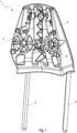
- Figure 1 shows a headrest 1 according to the invention, in which Figure 1 only the head box 2 and two frame rods 3 are shown.
- Figure 1 shows the side that faces the person on the vehicle seat 1 when, for example, a cover (not shown) and a perforated, one-piece foam body 7 (not shown) have been removed.
- this foam body 7 is designed in such a way that it forms a cavity in its interior.
- Figure 1 The side of the headrest 1 shown is therefore the front.
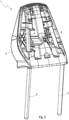
- Figure 2 shows the headrest 1 from Figure 1 in a view that corresponds to the view from Figure 1 is arranged opposite, that is, the headrest 1 is in Figure 2 shown as back.
- the head box 2 is formed in one piece and has two areas, each of which allows for the accommodation of a loudspeaker 5. These two areas are designed as loudspeaker recesses 4.
- a loudspeaker 5 in the form of two individual loudspeakers 5a, 5b for the headrest 1 is in Figure 3 Furthermore, Figure 3 a loudspeaker cable 6, with which the respective individual loudspeaker 5a, 5b can be controlled.
- the loudspeaker recesses 4 in the head box 2 after Figures 1 and 2 are designed in such a way that the one-piece head box 2 has at least one opening at these points, so that sound waves from the respective loudspeaker 5 in the loudspeaker cavity 4 can strike directly the perforated area 7a of the foam body 7 and subsequently the cover (not shown).
- Six openings are marked, which are assigned to a respective loudspeaker recess 4 in the head box 2. This means that each loudspeaker recess 4 has six openings.
- the loudspeakers 5 are screwed into the respective loudspeaker recess 4, although this is not shown in the figures.
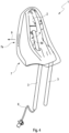
- Figure 4 shows a headrest 1 according to the Figures 1 and 2 , which has, among other things, a head box 2 and two frame rods 3.
- Figure 4 One individual loudspeaker 5a, 5b each Figure 3 inserted and screwed to the head box 2.
- the foam body 7 is indicated, whereby after Figure 4 the head box 2 is arranged between the loudspeaker 5 and the foam body 7 in relation to the front. In relation to the back, the foam body 7 covers the two frame rods 3 and the loudspeaker 5. The back of the headrest 1 is thus also suitably covered or wrapped by the foam body 2. The components are thus lying in the cavity of the foam body 7 when the foam body 7 is pulled over the components.
- the foam body 7 is Figure 4 in the front area towards the front side. This creates a perforated area 7a in this area.
- the Figure 4 The components of the headrest 1 shown are only indicated or can be indicated due to the schematic representation.
- the foam body 7 is thus placed on the head box 2 in Figure 4 applied in such a way that it snugly encloses the head box 2, the two frame rods 3 in the area of the head box 2 and the loudspeaker 5.
- this headrest 1 can be covered by a cover (not shown).
- the area of the foam body 7 that faces towards the back of the headrest 1 forms the resonance volume between the loudspeaker 5 and the foam body 7 itself.
- the return sound that is generated by the loudspeaker 5 towards the back of the headrest 1 is dissipated.
- the foam body 7 itself thus acts as a resonance body in its area on the back, whereby no further cover in the form of, for example, another cover cap or the like is necessary to create such an effect.
Landscapes
- Engineering & Computer Science (AREA)
- Physics & Mathematics (AREA)
- Acoustics & Sound (AREA)
- Signal Processing (AREA)
- Aviation & Aerospace Engineering (AREA)
- Transportation (AREA)
- Mechanical Engineering (AREA)
- Health & Medical Sciences (AREA)
- Otolaryngology (AREA)
- Chair Legs, Seat Parts, And Backrests (AREA)
- Seats For Vehicles (AREA)
- Details Of Audible-Bandwidth Transducers (AREA)
Description
- Die Erfindung betrifft eine Kopfstütze für einen Fahrzeugsitz für ein Fahrzeug für zumindest eine Person, wobei die Kopfstütze eine Vorderseite aufweist, die in Richtung der Person weist, die auf dem Fahrzeugsitz sitzt, und eine Rückseite aufweist, die gegenüber der Vorderseite der Kopfstütze angeordnet ist.
- Kopfstützen bei Fahrzeugsitzen sind derart bekannt, dass die Kopfstütze in eine Rückenlehne eines Fahrzeugsitzes direkt mit integriert sein kann, so dass sich ein Bauteil ergibt, oder alternativ über ein Gestell die Kopfstütze mit der Rückenlehne eines Fahrzeugsitzes bewegbar verbunden wird. Es ist bekannt, dass ein Fahrzeugsitz zumindest neben der Rückenlehne, an den der Rücken einer Person angelehnt werden kann, auch eine Sitzfläche aufweist, wobei die Rückenlehne und die Sitzfläche gegeneinander verschiebbar sind. Alternativ sind die Rückenlehne und die Sitzfläche starr zueinander angeordnet.
- Ferner ist bekannt, einen Lautsprecher in die Kopfstütze eines Fahrzeugsitzes zu integrieren, so dass die Person beispielsweise während der Fahrt auf dem Fahrzeugsitz mittels der Kopfstütze Musik hören kann. Dabei weist die Rückseite der Kopfstütze eine Abdeckung, beispielweise eine Abdeckung aus Kunststoff, auf, um ein Resonanzvolumen auf der Rückseite des Lautsprechers bilden zu können. Über einer solchen Abdeckung ist Schaumstoff in Richtung Außenseite der Kopfstütze vorhanden.
- Die
DE 25 28 988 A1 beschreibt eine Kopfstütze mit Lautsprechern. Hierbei dient ein Schaumstoff einer Polsterung dazu, in die rückwärtigen Räume der Lautsprecher austretende Schwingungen zu dämpfen beziehungsweise zu absorbieren. - Eine weitere Kopfstütze mit integrierter Lautsprecheranordnung ist in der
EP 1 077 156 A1 beschrieben. - Aus der
US 3,944,020 A , derUS 2015/0298372 A1 und derEP 3 370 439 A1 sind jeweils eine Kopfstütze für ein Fahrzeug bekannt. - Nachteilig ist, dass der Aufbau einer Kopfstütze mit einem Lautsprecher oder ohne einen Lautsprecher komplex ist, so dass sich je nach Ausgestaltung der Kopfstütze verschiedene konstruktive Lösungen ermöglichen, insbesondere bei einer Anordnung eines Lautsprechers in einer Kopfstütze.
- Die Aufgabe der Erfindung besteht darin, eine Möglichkeit zu schaffen, die unabhängig von der Ausgestaltung der Kopfstütze eine einfache konstruktive Lösung ermöglicht.
- Die Aufgabe wird gemäß dem unabhängigen Patentanspruch 1 gelöst. Weiterbildungen der Erfindung ergeben sich aus den abhängigen Ansprüchen.
- Zur Lösung der Aufgabe weist die Kopfstütze einen Kopfkasten und zumindest einen Schaumkörper auf, wobei der Schaumkörper um zumindest einen Teil des Kopfkastens herum aufbringbar ist und dabei zumindest einen Teil des in Richtung der Vorderseite der Kopfstütze angeordneten Teils des Kopfkastens bedeckt und dabei zumindest einen Teil des in Richtung der Rückseite der Kopfstütze angeordneten Teils des Kopfkastens bedeckt und der Schaumkörper derart ausgestaltet ist, dass der Teil des Schaumkörpers, der die Rückseite des Kopfkastens bedeckt, ein Resonanzvolumen bildet.
- Dadurch ist es vorteilhaft möglich, dass eine einfache konstruktive Lösung in Form einer Reduktion von mehreren Bauteilen für den Kopfkasten ermöglicht wird. Auch kann ein Schaumkörper unabhängig von verschiedenen Varianten der Kopfstütze, beispielweise eine Kopfstütze mit Lautsprecher oder ohne Lautsprecher, genutzt werden. In der Variante mit Lautsprecher dient der erfindungsgemäße Schaumkörper dabei auf der Rückseite der Kopfstütze als Resonanzkörper, der das Resonanzvolumen bildet. Dieses bedeutet, dass der Schaumkörper auf der Rückseite eine Dissipation von Schallwellen von dem Lautsprecher durchführt, indem er das Resonanzvolumen bildet. Der Schaumkörper wirkt somit als Resonanzkörper.
- Es ist nach der Erfindung somit möglich auf eine weitere Abdeckung, die ein Resonanzvolumen erzeugen soll, zwischen Lautsprecher und Rückseite der Kopfstütze zu verzichten. Eine solche Abdeckung kann zum Beispiel als Abdeckkappe ausgebildet sein. Nach der Erfindung ist aber eine solche Abdeckung nicht notwendig. Der Schaumkörperbereich in Richtung der Rückseite des Lautsprechers bildet das Resonanzvolumen aus, indem die Offenporigkeit des Schaumkörpers die Schallwellen, die der Lautsprecher rückseitig abstrahlt, passend als Resonanzkörper aufnimmt. Die Schallwellen, die in Richtung Rückseite von dem Lautsprecher erzeugt werden, diffundieren somit in diesen Schaumkörperbereich auf der Rückseite der Kopfstütze. Es entsteht eine Dissipation von Schallwellen in dem Schaumkörperbereich auf der Rückseite der Kopfstütze.
- Die Kopfstütze weist zumindest einen Lautsprecher auf. Beispielsweise ist es möglich, dass die Kopfstütze zwei Lautsprecher aufweist. Die Lautsprecher können mit dem Kopfkasten mittels zumindest einer Schraube verschraubt sein.
- Der Lautsprecher ist zwischen einer Rückseite des Kopfkastens und einem Bereich des Schaumkörpers angeordnet und eine Vorderseite des Kopfkastens ist nur von dem Schaumkörper bedeckt. Der Lautsprecher an sich ist dabei bevorzugt in Richtung Vorderseite der Kopfstütze ausgerichtet, so dass die Schallwellen aus dem Lautsprecher in Richtung Person durch den Bereich des Schaumkörpers geleitet werden können.
- In dem Bereich des Schaumkörpers, der die Rückseite der Kopfstütze bildet, findet eine Dissipation des Rückschalls von einem Lautsprecher in der Kopfstütze nach der Erfindung somit statt. Somit ist keine weitere Abdeckung notwendig, um einen solchen Dissipations-Effekt zu erzeugen. Das heißt, der Schaumkörper führt die Dissipation nach der Erfindung durch.
- Der Schaumkörper weist zumindest einen Bereich auf, der perforiert ist, so dass zumindest dieser perforierte Bereich des Schaumkörpers der Kopfstütze für die Transmission zumindest einer Schallwelle aus dem Lautsprecher genutzt werden kann.
- Unter einer Perforation im Sinne der Erfindung ist zu verstehen, dass der Schaumkörper an dieser Stelle eine andere Dichte aufweist als der Schaumkörper an einer anderen Stellen des Schaumkörpers. Technisch kann dieses durch eine spezielle Kontur, bspw. zumindest ein Loch in dem Schaumkörper, in dem Schaum erzeugt werden. Es ist somit nach der Erfindung möglich, dass vorhandene Öffnungen im Kopfkasten, um den Schall aus einem Lautsprecher in der Kopfstütze passend durch diese Öffnungen hindurch zu leiten, mit der Perforation im Schaumkörper vor diesen Öffnungen im Kopfkasten sich überdecken oder passend angeordnet sind. Alternativ oder ergänzend können auch weitere Perforationen in den Schaumkörper eingebracht sein, um den Schall durch den Schaumkörper zu emittieren. Eine Perforation in dem Schaumkörper nach der Erfindung kann somit ein Loch, eine spezielle Freiform oder zum Beispiel eine Raute, ein Quadrat, eine Ellipse oder dergleichen sein. Bevorzugt ist die jeweilige Perforation vollständig durch den Schaumkörper durchgehend, das heißt, der Schall kann vom Lautsprecher beziehungsweise Kopfkasten durch die Perforation auf die Außenseite des Schaumkörpers geleitet werden.
- Der Kopfkasten weist zumindest eine Öffnung auf, durch die die Schallwelle aus dem Lautsprecher in der Kopfstütze durch den perforierten Bereich des Schaumkörpers hindurch dringen kann. Diese Schallwellen treffen dann bevorzugt auf den Bezug und nachfolgend auf die Person auf dem Fahrzeugsitz.
- In einer bevorzugten Variante der Kopfstütze ist der Kopfkasten einteilig ausgebildet.
- In einer weiteren vorteilhaften Ausgestaltung weist die Kopfstütze einen Bezug auf, der den Kopfkasten und den Schaumkörper bedeckt, insbesondere den Kopfkasten, den Schaumkörper und den Lautsprecher bedeckt. Ein solcher Bezug schützt die Kopfstütze vor äußeren Einflüssen und verdeckt die Bauteile der Kopfstütze.
- Es ist möglich, dass der Bezug aus Leder, Baumwolle und/oder einem Polymer besteht.
- In einer weiteren vorteilhaften Ausgestaltung ist der Bezug zumindest teilweise perforiert, insbesondere im Bereich der Vorderseite der Kopfstütze.
- Dadurch kann eine Person besonders gut einen Ton, das heißt die Schallwelle, aus dem Lautsprecher durch den Bezug und den Schaumkörper hören.
- In einer weiteren vorteilhaften Ausgestaltung ist der Schaumkörper einteilig ausgebildet.
- In einer weiteren vorteilhaften Ausgestaltung ist der Schaumkörper der Kontur des Kopfkastens angepasst, insbesondere im Inneren eine Höhle aufweisend, in die zumindest ein Teil des Kopfkastens eingebracht werden kann, so dass der Kopfkasten zumindest teilweise umhüllt ist, insbesondere dessen Vorderseite und Rückseite umhüllt. Durch die Umhüllung können auch Teile der beiden Seitenbereiche und der obere Bereich des Kopfkastens mit umhüllt werden. Bevorzugt wird die Unterseite des Kopfkastens nicht umhüllt. Die Unterseite liegt gegenüber dem oberen Bereich des Kopfkasten und ist bezogen auf eine gedachte Achse zwischen Vorder- und Rückseite oder den beiden Seitenbereichen senkrecht dazu angeordnet, das heißt mit einem 90 ° Winkel.
- Eine Höhle kann im Sinne der Erfindung derart aufgefasst werden, dass Teile der Kopfstütze, wie der Kopfkasten, der Lautsprecher und/oder das Gestell in die Höhle, die das Innere des Schaumkörpers ausbildet, eingebracht werden können. Beim Überziehen des erfindungsgemäßen Schaumkörpers über den Kopfkasten wird somit der Kopfkasten von der innen liegenden Höhle des Schaumkörpers aufgenommen. Dadurch wird in diesem konkreten Beispiel der Kopfkasten umhüllt. Der Kopfkasten ist somit zumindest an der Oberseite, der Vorder- und Rückseite sowie seinen beiden Seitenbereichen vollständig durch den Schaumkörper bedeckt.
- Die Kopfstütze ist somit nach der Erfindung modular aufgebaut, das heißt, es ist einfach konstruktiv aufzubauen, indem die Kopfstütze zumindest einen, bevorzugt einteiligen, Kopfkasten und zumindest einen Schaumkörper gemäß Anspruch 1 aufweist. Alternativ oder ergänzend kann somit auch ein, bevorzugt einteiliger, Kopfkasten verwendet werden
- Es ist ferner nach der Erfindung möglich, dass der Schaumkörper mehrteilig aufgebaut ist, beispielweise aus zwei Einzeleilen besteht, wobei der eine Teil für die Vorderseite und der andere Teil für die Rückseite der Kopfstütze verwendet werden kann. Die Einzelteile können nach der Erfindung zusammengeführt werden, so dass sich ein einziger Schaumkörper ergibt.
- Die Kopfstütze ist in einer vorteilhaften Ausgestaltung mit einem Gestell an der Rückenlehne eines Fahrzeugsitzes verbunden, wobei die Kopfstütze mittels des Gestells gegenüber der Rückenlehne verschiebbar ist. Das Gestell weist bevorzugt zwei Gestellstangen auf, die beispielsweise an dem Kopfkasten befestigt sind. Der Fahrzeugsitz selbst besteht bevorzugt aus einer Sitzfläche und einer dazu bewegbaren Rückenlehne.
- In einer weiteren vorteilhaften Ausgestaltung ist es möglich, dass ergänzend die Gestellstangen im Bereich des Kopfkastens mit von dem Schaumkörper bedeckt, das heißt umhüllt, werden.
- Bevorzugt besteht der Schaumkörper aus aufgeschäumten PUR-Schaum, insbesondere ein PUR-Schaum (Polyurethan-Schaum) in der MDI-Variante (Methylendiphenylisocyanat-Variante).
- In einer weiteren vorteilhaften Ausgestaltung ist die Breite der Kopfstütze zwischen 150 bis 350 mm, vorzugsweise zwischen etwa 215 bis 255 mm.
- In einer weiteren vorteilhaften Ausgestaltung ist die Höhe der Kopfstütze zwischen 150 bis 350 mm, vorzugsweise zwischen etwa 230 bis 270 mm.
- In einer weiteren vorteilhaften Ausgestaltung ist die Dicke, das heißt der Distanz zwischen Vorder- und Rückseite, der Kopfstütze zwischen 80 bis 200 mm, vorzugsweise zwischen etwa 120 bis 160 mm.
- In einer weiteren vorteilhaften Ausgestaltung ist die Dichte des Schaumkörpers der Kopfstütze zwischen 55 bis 70 kg/m3. Bevorzugt ist die Stauchhärte dabei zwischen 4,5 bis 6,75 kPa. Bevorzugt ist der Schaumkörper offenporig gestaltet.
- Ferner betrifft die vorliegende Offenbarung ein Verfahren zur Herstellung eines Schaumkörpers, insbesondere eines Schaumkörpers für eine Kopfstütze, wobei der Schaumkörper in der Art hergestellt wird, dass in einem Bereich in einem Werkzeug einer Werkzeugmaschine ein Konturwerkzeug bewegbar eingebracht wird, so dass in diesem Bereich beim Aufschäumen des Schaumkörpers in dem Werkzeug sich eine Perforation durch das Konturwerkzeug in diesem Bereich des Schaumkörpers während der Herstellung des Schaumkörpers ergibt. Nach der Herstellung weist der Schaumkörper einen perforierten Bereich auf. Der perforierte Bereich kann beispielsweise ein Loch in dem Schaumkörper sein.
- Ferner betrifft die vorliegende Offenbarung eine Werkzeugmaschine für das Aufschäumen von Schäumen in einem Werkzeug, dadurch gekennzeichnet, dass die Werkzeugmaschine Mittel aufweist, um das Verfahren zur Herstellung eines Schaumkörpers durchführen zu können.
- Es ist somit nach der Erfindung möglich, einen einteiligen Schaumkörper in einer Kopfstütze zu verwenden, der den einteiligen Kopfkasten insoweit nahezu vollständig oder vollständig umhüllt, indem in Richtung Vorderseite der Kopfstütze Schallwellen, beispielsweise ein Ton aus dem Lautsprecher der Kopfstütze, durch den perforierten Bereich des Schaumkörpers nach außen in Richtung Person auf dem Sitz dringen kann und indem in Richtung Rückseite der Kopfstütze die rückseitig abgegebenen Schallwellen des Lautsprechers durch den auf der Rückseite der Kopfstütze angeordneten Schaumkörperbereich durch Dissipation aufgenommen werden, so dass sich nach der Erfindung ein Resonanzvolumen im hinteren Bereich der Kopfstütze dadurch ausbildet. Eine ergänzende Abdeckung, die ein solches Resonanzvolumen auch erzeugen könnte, ist somit nicht nach der Erfindung notwendig. Erfindungsgemäß bildet der Bereich des einteiligen Schaumköpers im Bereich der Rückseite der Kopfstütze dieses Resonanzvolumen passend aus.
- Der Schaumkörper ist dabei in einer Ausgestaltung mützenartig ausgestaltet, so dass der Schaumkörper in einer Modulvariante über den einteiligen Kopfkasten, die beiden Lautsprecher und zwei Gestellstangen übergezogen werden kann, so dass dieser Schaumkörper diese Bauteile der Kopfstütze umhüllt, das heißt diese bedeckt. Eine gegebenenfalls vorliegende Perforation in einem Bereich der Kopfstütze wird dann passend in Richtung Vorderseite der Kopfstütze im Rahmen der Umhüllung ausgerichtet, so dass die Schallwellen passend nach außen in Richtung Person austreten können.
- Weitere Bauteile, wie Schrauben, Kabel oder dergleichen, die für die Funktion der Kopfstütze mit oder ohne Lautsprecher notwendig sind, werden folglich im Rahmen eines mützenartig ausgestalteten Schaumkörpers mit umhüllt.
- Weitere Vorteile und Einzelheiten der Erfindung ergeben sich aus dem folgenden Ausführungsbeispiel sowie den zugehörigen Zeichnungen. Hierbei zeigen schematisch, wobei identische oder technisch in der Funktion gleiche Bauteile oder Komponenten mit gleichen Bezugsziffern versehen sind:
- Fig. 1
- eine schematische Darstellung eines Kopfkasten mit Gestell einer erfindungsgemäßen Kopfstütze in perspektivischer Vorderansicht,
- Fig. 2
- eine schematische Darstellung eines Kopfkasten mit Gestell einer erfindungsgemäßen Kopfstütze in perspektivischer Rückansicht,
- Fig. 3
- eine schematische Darstellung eines Lautsprechers für eine erfindungsgemäße Kopfstütze in perspektivischer Ansicht und
- Fig. 4
- eine schematische Darstellung einer erfindungsgemäßen Kopfstütze in perspektivischer Seitenansicht.
-
Figur 1 zeigt eine erfindungsgemäße Kopfstütze 1, wobei inFigur 1 nur der Kopfkasten 2 und zwei Gestellstangen 3 dargestellt sind.Figur 1 zeigt dabei die Seite, die in Richtung Person auf dem Fahrzeugsitz 1 weist, wenn zum Beispiel ein nicht dargestellter Bezug sowie ein nicht dargestellter perforierter, einteiliger Schaumkörper 7 entfernt worden sind. Dieser Schaumkörper 7 ist in diesem Ausführungsbeispiel derart ausgebildet, dass er eine Höhle in seinem Inneren ausbildet. - Die in
Figur 1 dargestellte Seite der Kopfstütze 1 ist somit die Vorderseite.Figur 2 zeigt die Kopfstütze 1 ausFigur 1 in einer Ansicht, die der Ansicht ausFigur 1 gegenüberliegend angeordnet ist, das heißt die Kopfstütze 1 ist inFigur 2 als Rückseite dargestellt. - Der Kopfkasten 2 ist dabei einteilig ausgebildet und weist zwei Bereiche auf, die die Aufnahme jeweils eines Lautsprechers 5 ermöglichen. Diese beiden Bereiche sind als Lautsprechermulden 4 ausgebildet.
- Ein Lautsprecher 5 in Form von zwei Einzellautsprechern 5a, 5b für die Kopfstütze 1 ist in
Figur 3 dargestellt. Des Weiteren zeigtFigur 3 ein Lautsprecherkabel 6, mit dem der jeweilige Einzellautsprecher 5a, 5b angesteuert werden kann. - Die Lautsprechermulden 4 in dem Kopfkasten 2 nach
Figuren 1 und2 sind derart ausgebildet, dass an diesen Stellen der einteilige Kopfkasten 2 zumindest eine Öffnung aufweist, so dass Schallwellen aus dem jeweiligen Lautsprecher 5 in der Lautsprechermulde 4 direkt auf den perforierten Bereich 7a des Schaumkörpers 7 und nachfolgend auf den nicht dargestellten Bezug auftreffen können. In derFigur 1 sind sechs Öffnungen eingezeichnet, die einer jeweiligen Lautsprechermulde 4 im Kopfkasten 2 zugeordnet sind. Das heißt jede Lautsprechermulde 4 hat sechs Öffnungen. Die Lautsprecher 5 werden in der jeweiligen Lautsprechermulde 4 verschraubt, wobei dieses nicht in den Figuren dargestellt ist. -
Figur 4 zeigt eine Kopfstütze 1 nach denFiguren 1 und2 , die unter anderem einen Kopfkasten 2 und ferner zwei Gestellstangen 3 aufweist. In die beiden Lautsprechermulden 4 ist nachFigur 4 jeweils ein Einzellautsprecher 5a, 5b nachFigur 3 eingesetzt und passend mit dem Kopfkasten 2 verschraubt. - In Richtung Vorderseite der Kopfstütze 1 ist nach
Figur 4 der Schaumkörper 7 angedeutet, wobei nachFigur 4 der Kopfkasten 2 zwischen Lautsprecher 5 und Schaumkörper 7 bezogen auf die Vorderseite angeordnet ist. Bezogen auf die Rückseite verdeckt der Schaumkörper 7 die zwei Gestellstangen 3 sowie den Lautsprecher 5. Die Rückseite der Kopfstütze 1 ist somit auch durch den Schaumköper 2 passend abgedeckt bzw. umhüllt. Die Bauteile sind somit in der sich ausbildenden Höhle des Schaumkörpers 7 liegend, wenn der Schaumkörper 7 über die Bauteile gezogen ist. Der Schaumkörper 7 ist nachFigur 4 im vorderen Bereich in Richtung Vorderseite perforiert ausgestaltet. Es bildet sich somit in diesem Bereich ein perforierter Bereich 7a aus. Die inFigur 4 dargestellten Bauteile der Kopfstütze 1 sind aufgrund der schematischen Darstellung nur angedeutet bzw. andeutbar. - Der Schaumkörper 7 ist somit auf den Kopfkasten 2 in
Figur 4 derart aufgebracht, dass dieser den Kopfkasten 2, die zwei Gestellstangen 3 im Bereich des Kopfkastens 2 und den Lautsprecher 5 passend umhüllt. - Diese Kopfstütze 1 kann nach der Erfindung von einem nicht dargestellten Bezug umhüllt sein.
- Wenn Schall 9, das heißt ein Ton oder eine Schallwelle, aus einem Lautsprecher 5 kommt, wird dieser durch die Öffnungen der Lautsprechermulden 4, nachfolgend durch den perforierten Bereich 7a des Schallkörpers 7, das heißt beispielhaft eine durchgehende Öffnung nach Art eines Lochs, und den nicht dargestellten Bezug auf die Person auf dem Fahrzeugsitz 1 geleitet. Es erfolgt somit eine Transmission in Richtung Vorderseite durch den Schall 9.
- Der Bereich des Schaumkörpers 7, der in Richtung Rückseite der Kopfstütze 1 weist, bildet dabei das Resonanzvolumen zwischen Lautsprecher 5 und Schaumkörper 7 selbst. In diesem Resonanzvolumen des Schaumkörpers 7 findet Dissipation des Rückschalls statt, der in Richtung Rückseite der Kopfstütze 1 vom Lautsprecher 5 erzeugt wird. Der Schaumkörper 7 selbst wirkt somit in seinem Bereich auf der Rückseite als Resonanzkörper, wobei keine weitere Abdeckung in Form zum Beispiel einer weiteren Abdeckkappe oder dergleichen notwendig ist, um einen solchen Effekt zu erzeugen.
Claims (6)
- Kopfstütze (1) für einen Fahrzeugsitz für ein Fahrzeug für zumindest eine Person, wobei die Kopfstütze (1) eine Vorderseite aufweist, die in Richtung der Person weist, die auf dem Fahrzeugsitz sitzt, und eine Rückseite aufweist, die gegenüber der Vorderseite der Kopfstütze (2) angeordnet ist, wobei die Kopfstütze einen Kopfkasten (2) und zumindest einen Schaumkörper (7) aufweist, wobei der Schaumkörper (7) um zumindest einen Teil des Kopfkastens (2) herum aufbringbar ist und dabei zumindest einen Teil des in Richtung der Vorderseite der Kopfstütze angeordneten Teils des Kopfkastens (2), nämlich eine Vorderseite des Kopfkastens, bedeckt und dabei zumindest einen Teil des in Richtung der Rückseite der Kopfstütze angeordneten Teils des Kopfkastens (2), nämlich eine Rückseite des Kopfkastens, bedeckt, wobei die Kopfstütze (1) zumindest einen Lautsprecher (5) aufweist und der Schaumkörper derart ausgestaltet ist, dass der Teil des Schaumkörpers (7), der die Rückseite des Kopfkastens (2) bedeckt, ein Resonanzvolumen bildet, wobei der Schaumkörper (7) auf der Rückseite eine Dissipation von Schallwellen von dem Lautsprecher durchführt, wobei der Schaumkörper (7) als Resonanzkörper wirkt, dadurch gekennzeichnet, dass der Lautsprecher (5) zwischen der Rückseite des Kopfkastens (2) und dem Teil des Schaumkörpers, der die Rückseite des Kopfkastens bedeckt, angeordnet ist, und die der Rückseite des Kopfkastens (2) gegenüberliegend angeordnete Vorderseite des Kopfkastens (2) nur von dem Schaumkörper (7) bedeckt ist, wobei die Vorderseite des Kopfkastens (2) in Richtung der Person auf dem Fahrzeugsitz (1) weist, wobei der Schaumkörper (7) zumindest einen Bereich aufweist, der perforiert ist, und wobei der Kopfkasten (2) zumindest eine Öffnung aufweist, durch die die Schallwelle aus dem Lautsprecher (5) in der Kopfstütze (1) durch den perforierten Bereich (7a) des Schaumkörpers (7) hindurch nach außen in Richtung Person auf dem Fahrzeugsitz (1) dringen kann.
- Kopfstütze nach Anspruch 1, dadurch gekennzeichnet, dass der Kopfkasten (2) einteilig ausgebildet ist.
- Kopfstütze nach einem der vorhergehenden Ansprüche, dadurch gekennzeichnet, dass die Kopfstütze (1) einen Bezug aufweist, der den Kopfkasten und den Schaumkörper (7) bedeckt, insbesondere den Kopfkasten, den Schaumkörper und den Lautsprecher bedeckt.
- Kopfstütze nach einem der vorhergehenden Ansprüche, dadurch gekennzeichnet, dass der Bezug zumindest teilweise perforiert ist, insbesondere im Bereich der Vorderseite der Kopfstütze (1) perforiert ist.
- Kopfstütze nach einem der vorhergehenden Ansprüche, dadurch gekennzeichnet, dass der Schaumkörper (7) einteilig ausgebildet ist.
- Kopfstütze nach einem der vorhergehenden Ansprüche, dadurch gekennzeichnet, dass der Schaumkörper (7) der Kontur des Kopfkastens (2) angepasst ist, insbesondere im Inneren eine Höhle aufweisend, in die zumindest ein Teil des Kopfkastens (2) eingebracht werden kann, so dass der Kopfkasten (2) zumindest teilweise umhüllt ist, insbesondere dessen Vorderseite und Rückseite umhüllt.
Applications Claiming Priority (2)
| Application Number | Priority Date | Filing Date | Title |
|---|---|---|---|
| DE102019206715.8A DE102019206715A1 (de) | 2019-05-09 | 2019-05-09 | Kopfstütze |
| PCT/EP2020/061035 WO2020224945A1 (de) | 2019-05-09 | 2020-04-21 | Kopfstütze |
Publications (2)
| Publication Number | Publication Date |
|---|---|
| EP3967053A1 EP3967053A1 (de) | 2022-03-16 |
| EP3967053B1 true EP3967053B1 (de) | 2024-09-18 |
Family
ID=70456750
Family Applications (1)
| Application Number | Title | Priority Date | Filing Date |
|---|---|---|---|
| EP20721179.8A Active EP3967053B1 (de) | 2019-05-09 | 2020-04-21 | Kopfstütze |
Country Status (5)
| Country | Link |
|---|---|
| US (1) | US20220219587A1 (de) |
| EP (1) | EP3967053B1 (de) |
| CN (1) | CN113812169B (de) |
| DE (1) | DE102019206715A1 (de) |
| WO (1) | WO2020224945A1 (de) |
Families Citing this family (2)
| Publication number | Priority date | Publication date | Assignee | Title |
|---|---|---|---|---|
| US12403806B2 (en) | 2021-02-16 | 2025-09-02 | Adient Us Llc | Head restraint for a vehicle seat, and vehicle seat |
| DE102021112215A1 (de) | 2021-02-16 | 2022-08-18 | Adient Engineering and IP GmbH | Kopfstütze für einen Fahrzeugsitz und Fahrzeugsitz |
Family Cites Families (52)
| Publication number | Priority date | Publication date | Assignee | Title |
|---|---|---|---|---|
| US3290450A (en) * | 1962-12-21 | 1966-12-06 | Majoros Barna | Pillow type speaker support |
| US3384719A (en) * | 1964-10-21 | 1968-05-21 | Gen Electric | Stereophonic speaker arrangement |
| US3512605A (en) * | 1967-08-31 | 1970-05-19 | David D Mccorkle | Stereo speaker headrest for an automobile seat |
| US3385393A (en) * | 1967-09-15 | 1968-05-28 | Pacific Internat Plastics | Headrest and speaker apparatus |
| US3944020A (en) * | 1974-07-17 | 1976-03-16 | Ronald Leroy Brown | Speaker headrest for motor vehicles |
| DE7508842U (de) * | 1974-12-20 | 1976-01-02 | Blaupunkt-Werke Gmbh, 3200 Hildesheim | Kopfstuetze mit lautsprecher |
| US4042791A (en) * | 1975-02-27 | 1977-08-16 | Murriel L. Wiseman | Stereophonic head rest |
| US4038499A (en) * | 1976-02-02 | 1977-07-26 | Yeaple Corporation | Stereophonic pillow speaker system |
| US4782533A (en) * | 1987-01-12 | 1988-11-01 | Haynie James L | Stereophonic pillow speaker system |
| JPH0736633B2 (ja) * | 1990-10-31 | 1995-04-19 | 松下電器産業株式会社 | スピーカ前面シート |
| KR960001089Y1 (ko) * | 1993-01-12 | 1996-02-07 | 조철수 | 자동차용 다기능 헤드레스트의 프레임 |
| DE19938170C2 (de) * | 1999-08-16 | 2003-05-22 | Daimler Chrysler Ag | Kopfstütze für ein Fahrzeug |
| FR2829980B1 (fr) * | 2001-09-26 | 2004-01-30 | Security Vision Concept | Procede de montage d'un boitier sur un coussin muni d'une housse d'habillage, housse d'habillage equipee d'un boitier et le coussin revetu de cette housse |
| US7668329B2 (en) * | 2005-07-12 | 2010-02-23 | Tachi-S Co., Ltd. | Acoustin structure of seat back |
| US20100148550A1 (en) * | 2008-12-11 | 2010-06-17 | Gm Global Technology Operations, Inc. | Audio headrest for attachment to a seat of a vehicle |
| US8783767B2 (en) * | 2011-05-06 | 2014-07-22 | David Wood | Headrest media system for a seat back of a vehicle |
| ES2434858B1 (es) | 2012-06-13 | 2014-06-20 | Illinois Tool Works Inc. | Reposacabezas ligero optimizado según recursos de producción y procedimiento asociado al mismo |
| DE102013201813A1 (de) * | 2013-02-05 | 2014-08-07 | Johnson Controls Gmbh | Kopfstütze für ein Fahrzeug und Verfahren zu deren Herstellung |
| US9327628B2 (en) * | 2013-05-31 | 2016-05-03 | Bose Corporation | Automobile headrest |
| JP6285165B2 (ja) * | 2013-11-11 | 2018-02-28 | 株式会社デルタツーリング | 音響装置及びヘッドレスト |
| CN105745119B (zh) * | 2013-11-19 | 2020-05-12 | 歌乐株式会社 | 头枕装置以及声音采集装置 |
| US9699537B2 (en) * | 2014-01-14 | 2017-07-04 | Bose Corporation | Vehicle headrest with speakers |
| JP6329018B2 (ja) * | 2014-06-27 | 2018-05-23 | クラリオン株式会社 | ヘッドレスト装置 |
| EP3162622B1 (de) * | 2014-06-27 | 2019-04-24 | Clarion Co., Ltd. | Akustische vorrichtung |
| US9428090B2 (en) * | 2014-08-07 | 2016-08-30 | Bose Corporation | Headrest with speakers and method for manufacturing headrest cushion member |
| JP6440998B2 (ja) * | 2014-08-25 | 2018-12-19 | 株式会社タチエス | ヘッドレスト及び車両用シート |
| US9403454B2 (en) * | 2014-11-17 | 2016-08-02 | Bose Corporation | External attachments for speakers in seats |
| US9440566B2 (en) * | 2014-12-05 | 2016-09-13 | Bose Corporation | Lightweight acoustic enclosures |
| WO2016117687A1 (ja) * | 2015-01-23 | 2016-07-28 | 株式会社デルタツーリング | ヘッドレストの製造方法及びヘッドレスト |
| US10271119B2 (en) * | 2015-02-14 | 2019-04-23 | Delta Tooling Co., Ltd. | Headrest having speaker |
| FR3043249B1 (fr) * | 2015-10-28 | 2018-03-09 | Commissariat A L'energie Atomique Et Aux Energies Alternatives | Cellule logique photosensible a illumination par la face avant |
| US9756408B2 (en) * | 2016-01-25 | 2017-09-05 | Ford Global Technologies, Llc | Integrated sound system |
| WO2017204125A1 (ja) * | 2016-05-25 | 2017-11-30 | 株式会社タチエス | ヘッドレスト及び車両用シート |
| JP6674850B2 (ja) * | 2016-06-29 | 2020-04-01 | クラリオン株式会社 | 収音装置 |
| CN109476248A (zh) * | 2016-07-26 | 2019-03-15 | 安道拓卢森堡控股有限公司 | 可调节的头枕 |
| US10293728B2 (en) * | 2016-08-24 | 2019-05-21 | Bose Corporation | Acoustic transducer assembly disposed in vehicle seat |
| EP3370439A1 (de) | 2017-03-01 | 2018-09-05 | Audio Mobil Elektronik GmbH | Kopfstütze mit lautsprechern für fahrzeugsitz |
| TWI689209B (zh) * | 2017-03-14 | 2020-03-21 | 大陸商廣東歐珀移動通信有限公司 | 揚聲器、揚聲裝置及行動終端 |
| DE102017214401B4 (de) * | 2017-08-18 | 2020-01-16 | Audi Ag | Mehrlagige Lautsprecherabdeckung und Fahrzeug |
| US10730423B2 (en) * | 2017-10-16 | 2020-08-04 | Bose Corporation | Vehicle headrest |
| US10596941B2 (en) * | 2017-12-19 | 2020-03-24 | Tachi-S Engineering U.S.A. Inc. | Headrest |
| JP7002010B2 (ja) * | 2018-05-31 | 2022-02-04 | パナソニックIpマネジメント株式会社 | スピーカシステムおよび騒音制御装置 |
| CN112334359B (zh) * | 2018-06-08 | 2023-04-07 | 伯斯有限公司 | 头枕 |
| US11110839B2 (en) * | 2018-06-08 | 2021-09-07 | Bose Corporation | Loudspeakers with 3D printed lattice grilles |
| US11535136B2 (en) * | 2019-03-08 | 2022-12-27 | Harman International Industries, Incorporated | Headrest with integrated nose and loudspeaker enclosure |
| CN115996863A (zh) * | 2020-08-31 | 2023-04-21 | 提爱思科技股份有限公司 | 头枕 |
| US11813970B2 (en) * | 2020-09-02 | 2023-11-14 | Continental Engineering Services Gmbh | Seating means with actuators for sound emission |
| FR3115504B1 (fr) * | 2020-10-22 | 2022-10-14 | Focal Jmlab | Appui-tete sonorise et siege associe |
| DE102021115982A1 (de) * | 2021-06-21 | 2022-12-22 | Bayerische Motoren Werke Aktiengesellschaft | Fahrzeugsitz mit einer Kopfstütze |
| DE102021119904A1 (de) * | 2021-07-30 | 2023-02-02 | Grammer Aktiengesellschaft | Ausstattungsteil für ein Fahrzeug mit Audio-Polstervorrichtung sowie Verfahren zur Herstellung eines Ausstattungsteils mit Audio-Polstervorrichtung |
| KR20230085297A (ko) * | 2021-12-07 | 2023-06-14 | 현대자동차주식회사 | 유연한 진동 쿠션 및 이의 구동 제어 방법 |
| KR20230091575A (ko) * | 2021-12-16 | 2023-06-23 | 현대자동차주식회사 | 스피커가 장착된 헤드레스트 |
-
2019
- 2019-05-09 DE DE102019206715.8A patent/DE102019206715A1/de active Pending
-
2020
- 2020-04-21 WO PCT/EP2020/061035 patent/WO2020224945A1/de not_active Ceased
- 2020-04-21 US US17/604,127 patent/US20220219587A1/en not_active Abandoned
- 2020-04-21 EP EP20721179.8A patent/EP3967053B1/de active Active
- 2020-04-21 CN CN202080034795.1A patent/CN113812169B/zh active Active
Also Published As
| Publication number | Publication date |
|---|---|
| US20220219587A1 (en) | 2022-07-14 |
| EP3967053A1 (de) | 2022-03-16 |
| CN113812169A (zh) | 2021-12-17 |
| CN113812169B (zh) | 2024-06-11 |
| WO2020224945A1 (de) | 2020-11-12 |
| DE102019206715A1 (de) | 2020-11-12 |
Similar Documents
| Publication | Publication Date | Title |
|---|---|---|
| DE19544266B4 (de) | Energieabsorbierende Fahrzeugtür | |
| DE102012200441A1 (de) | Anbringungsanordnung für Fahrzeugsitzrahmen und Verfahren zum Herstellen derselben | |
| DE102005052976A1 (de) | Fahrzeugtürverkleidungspolster mit Multi-Gefühl-Bezug und Verfahren zur Herstellung desselben | |
| EP3967053B1 (de) | Kopfstütze | |
| DE102017130373A1 (de) | Schutzhelm | |
| DE102016115507A1 (de) | Vorhangairbag für ein Fahrzeug | |
| EP3453565B1 (de) | Fahrzeugsitz, sitzbauteil sowie aufprallschutz | |
| DE102006001663B4 (de) | Vereinigtes, gepolstertes Innenausstattungsfeld für ein Fahrzeug | |
| DE2644499A1 (de) | Sicherheitsarmaturenbrett | |
| DE102015210526A1 (de) | Kopfstütze mit Lautsprechersystem für einen Kraftfahrzeugsitz und Kraftfahrzeugsitz mit einer solchen Kopfstütze | |
| DE102015109547A1 (de) | Geformte aktive Kunststoffkomponenten für eine Fahrzeugairbaganordnung | |
| EP3446584B1 (de) | Verfahren zum herstellen eines schutzhelms und nach diesem verfahren hergestellter schutzhelm | |
| DE102007053995A1 (de) | Verfahren zur Herstellung einer Instrumententafel eines Kraftfahrzeugs | |
| DE102021119904A1 (de) | Ausstattungsteil für ein Fahrzeug mit Audio-Polstervorrichtung sowie Verfahren zur Herstellung eines Ausstattungsteils mit Audio-Polstervorrichtung | |
| DE102014119057A1 (de) | Türinnenverkleidung mit einer Armauflage | |
| DE3010817C2 (de) | Knieschutzvorrichtung für ein Kraftfahrzeug | |
| DE102008032237A1 (de) | Armlehne für ein Fahrzeug | |
| DE102009026008A1 (de) | Stoßdämpfendes Element und Türverkleidung für ein Fahrzeug umfassend dasselbe | |
| DE102015210523B4 (de) | Kopfstütze mit Lautsprechersystem für einen Kraftfahrzeugsitz und Kraftfahrzeugsitz mit einer solchen Kopfstütze | |
| DE102008053232A1 (de) | Kollabierende Armauflage | |
| DE8120605U1 (de) | Schutzhelm | |
| DE102005029442B4 (de) | Gehäuse zur Aufnahme von elektro-akustischen Bauteilen | |
| DE19516012C1 (de) | Schutzhaube für einen Sitz eines Kraftfahrzeugs | |
| DE102005049836B4 (de) | Fahrzeugverkleidungsanordnung mit Aufprallschutzstrukturen und Verfahren zum Herstellen derselben | |
| DE102018205437B4 (de) | Vibrationsvorrichtung |
Legal Events
| Date | Code | Title | Description |
|---|---|---|---|
| STAA | Information on the status of an ep patent application or granted ep patent |
Free format text: STATUS: UNKNOWN |
|
| STAA | Information on the status of an ep patent application or granted ep patent |
Free format text: STATUS: THE INTERNATIONAL PUBLICATION HAS BEEN MADE |
|
| PUAI | Public reference made under article 153(3) epc to a published international application that has entered the european phase |
Free format text: ORIGINAL CODE: 0009012 |
|
| STAA | Information on the status of an ep patent application or granted ep patent |
Free format text: STATUS: REQUEST FOR EXAMINATION WAS MADE |
|
| 17P | Request for examination filed |
Effective date: 20211209 |
|
| AK | Designated contracting states |
Kind code of ref document: A1 Designated state(s): AL AT BE BG CH CY CZ DE DK EE ES FI FR GB GR HR HU IE IS IT LI LT LU LV MC MK MT NL NO PL PT RO RS SE SI SK SM TR |
|
| DAV | Request for validation of the european patent (deleted) | ||
| DAX | Request for extension of the european patent (deleted) | ||
| P01 | Opt-out of the competence of the unified patent court (upc) registered |
Effective date: 20230529 |
|
| GRAP | Despatch of communication of intention to grant a patent |
Free format text: ORIGINAL CODE: EPIDOSNIGR1 |
|
| STAA | Information on the status of an ep patent application or granted ep patent |
Free format text: STATUS: GRANT OF PATENT IS INTENDED |
|
| INTG | Intention to grant announced |
Effective date: 20240619 |
|
| GRAS | Grant fee paid |
Free format text: ORIGINAL CODE: EPIDOSNIGR3 |
|
| GRAA | (expected) grant |
Free format text: ORIGINAL CODE: 0009210 |
|
| STAA | Information on the status of an ep patent application or granted ep patent |
Free format text: STATUS: THE PATENT HAS BEEN GRANTED |
|
| AK | Designated contracting states |
Kind code of ref document: B1 Designated state(s): AL AT BE BG CH CY CZ DE DK EE ES FI FR GB GR HR HU IE IS IT LI LT LU LV MC MK MT NL NO PL PT RO RS SE SI SK SM TR |
|
| REG | Reference to a national code |
Ref country code: GB Ref legal event code: FG4D Free format text: NOT ENGLISH |
|
| REG | Reference to a national code |
Ref country code: CH Ref legal event code: EP |
|
| REG | Reference to a national code |
Ref country code: DE Ref legal event code: R096 Ref document number: 502020009270 Country of ref document: DE |
|
| REG | Reference to a national code |
Ref country code: IE Ref legal event code: FG4D Free format text: LANGUAGE OF EP DOCUMENT: GERMAN |
|
| REG | Reference to a national code |
Ref country code: LT Ref legal event code: MG9D |
|
| PG25 | Lapsed in a contracting state [announced via postgrant information from national office to epo] |
Ref country code: NO Free format text: LAPSE BECAUSE OF FAILURE TO SUBMIT A TRANSLATION OF THE DESCRIPTION OR TO PAY THE FEE WITHIN THE PRESCRIBED TIME-LIMIT Effective date: 20241218 |
|
| PG25 | Lapsed in a contracting state [announced via postgrant information from national office to epo] |
Ref country code: GR Free format text: LAPSE BECAUSE OF FAILURE TO SUBMIT A TRANSLATION OF THE DESCRIPTION OR TO PAY THE FEE WITHIN THE PRESCRIBED TIME-LIMIT Effective date: 20241219 Ref country code: FI Free format text: LAPSE BECAUSE OF FAILURE TO SUBMIT A TRANSLATION OF THE DESCRIPTION OR TO PAY THE FEE WITHIN THE PRESCRIBED TIME-LIMIT Effective date: 20240918 |
|
| PG25 | Lapsed in a contracting state [announced via postgrant information from national office to epo] |
Ref country code: BG Free format text: LAPSE BECAUSE OF FAILURE TO SUBMIT A TRANSLATION OF THE DESCRIPTION OR TO PAY THE FEE WITHIN THE PRESCRIBED TIME-LIMIT Effective date: 20240918 |
|
| PG25 | Lapsed in a contracting state [announced via postgrant information from national office to epo] |
Ref country code: LV Free format text: LAPSE BECAUSE OF FAILURE TO SUBMIT A TRANSLATION OF THE DESCRIPTION OR TO PAY THE FEE WITHIN THE PRESCRIBED TIME-LIMIT Effective date: 20240918 |
|
| PG25 | Lapsed in a contracting state [announced via postgrant information from national office to epo] |
Ref country code: HR Free format text: LAPSE BECAUSE OF FAILURE TO SUBMIT A TRANSLATION OF THE DESCRIPTION OR TO PAY THE FEE WITHIN THE PRESCRIBED TIME-LIMIT Effective date: 20240918 |
|
| REG | Reference to a national code |
Ref country code: NL Ref legal event code: MP Effective date: 20240918 |
|
| PG25 | Lapsed in a contracting state [announced via postgrant information from national office to epo] |
Ref country code: RS Free format text: LAPSE BECAUSE OF FAILURE TO SUBMIT A TRANSLATION OF THE DESCRIPTION OR TO PAY THE FEE WITHIN THE PRESCRIBED TIME-LIMIT Effective date: 20241218 |
|
| PG25 | Lapsed in a contracting state [announced via postgrant information from national office to epo] |
Ref country code: RS Free format text: LAPSE BECAUSE OF FAILURE TO SUBMIT A TRANSLATION OF THE DESCRIPTION OR TO PAY THE FEE WITHIN THE PRESCRIBED TIME-LIMIT Effective date: 20241218 Ref country code: NO Free format text: LAPSE BECAUSE OF FAILURE TO SUBMIT A TRANSLATION OF THE DESCRIPTION OR TO PAY THE FEE WITHIN THE PRESCRIBED TIME-LIMIT Effective date: 20241218 Ref country code: LV Free format text: LAPSE BECAUSE OF FAILURE TO SUBMIT A TRANSLATION OF THE DESCRIPTION OR TO PAY THE FEE WITHIN THE PRESCRIBED TIME-LIMIT Effective date: 20240918 Ref country code: HR Free format text: LAPSE BECAUSE OF FAILURE TO SUBMIT A TRANSLATION OF THE DESCRIPTION OR TO PAY THE FEE WITHIN THE PRESCRIBED TIME-LIMIT Effective date: 20240918 Ref country code: GR Free format text: LAPSE BECAUSE OF FAILURE TO SUBMIT A TRANSLATION OF THE DESCRIPTION OR TO PAY THE FEE WITHIN THE PRESCRIBED TIME-LIMIT Effective date: 20241219 Ref country code: FI Free format text: LAPSE BECAUSE OF FAILURE TO SUBMIT A TRANSLATION OF THE DESCRIPTION OR TO PAY THE FEE WITHIN THE PRESCRIBED TIME-LIMIT Effective date: 20240918 Ref country code: BG Free format text: LAPSE BECAUSE OF FAILURE TO SUBMIT A TRANSLATION OF THE DESCRIPTION OR TO PAY THE FEE WITHIN THE PRESCRIBED TIME-LIMIT Effective date: 20240918 |
|
| PG25 | Lapsed in a contracting state [announced via postgrant information from national office to epo] |
Ref country code: NL Free format text: LAPSE BECAUSE OF FAILURE TO SUBMIT A TRANSLATION OF THE DESCRIPTION OR TO PAY THE FEE WITHIN THE PRESCRIBED TIME-LIMIT Effective date: 20240918 |
|
| PG25 | Lapsed in a contracting state [announced via postgrant information from national office to epo] |
Ref country code: IS Free format text: LAPSE BECAUSE OF FAILURE TO SUBMIT A TRANSLATION OF THE DESCRIPTION OR TO PAY THE FEE WITHIN THE PRESCRIBED TIME-LIMIT Effective date: 20250118 Ref country code: PT Free format text: LAPSE BECAUSE OF FAILURE TO SUBMIT A TRANSLATION OF THE DESCRIPTION OR TO PAY THE FEE WITHIN THE PRESCRIBED TIME-LIMIT Effective date: 20250120 |
|
| PG25 | Lapsed in a contracting state [announced via postgrant information from national office to epo] |
Ref country code: RO Free format text: LAPSE BECAUSE OF FAILURE TO SUBMIT A TRANSLATION OF THE DESCRIPTION OR TO PAY THE FEE WITHIN THE PRESCRIBED TIME-LIMIT Effective date: 20240918 Ref country code: SM Free format text: LAPSE BECAUSE OF FAILURE TO SUBMIT A TRANSLATION OF THE DESCRIPTION OR TO PAY THE FEE WITHIN THE PRESCRIBED TIME-LIMIT Effective date: 20240918 |
|
| PG25 | Lapsed in a contracting state [announced via postgrant information from national office to epo] |
Ref country code: ES Free format text: LAPSE BECAUSE OF FAILURE TO SUBMIT A TRANSLATION OF THE DESCRIPTION OR TO PAY THE FEE WITHIN THE PRESCRIBED TIME-LIMIT Effective date: 20240918 |
|
| PG25 | Lapsed in a contracting state [announced via postgrant information from national office to epo] |
Ref country code: EE Free format text: LAPSE BECAUSE OF FAILURE TO SUBMIT A TRANSLATION OF THE DESCRIPTION OR TO PAY THE FEE WITHIN THE PRESCRIBED TIME-LIMIT Effective date: 20240918 |
|
| PG25 | Lapsed in a contracting state [announced via postgrant information from national office to epo] |
Ref country code: CZ Free format text: LAPSE BECAUSE OF FAILURE TO SUBMIT A TRANSLATION OF THE DESCRIPTION OR TO PAY THE FEE WITHIN THE PRESCRIBED TIME-LIMIT Effective date: 20240918 Ref country code: PL Free format text: LAPSE BECAUSE OF FAILURE TO SUBMIT A TRANSLATION OF THE DESCRIPTION OR TO PAY THE FEE WITHIN THE PRESCRIBED TIME-LIMIT Effective date: 20240918 |
|
| PG25 | Lapsed in a contracting state [announced via postgrant information from national office to epo] |
Ref country code: SK Free format text: LAPSE BECAUSE OF FAILURE TO SUBMIT A TRANSLATION OF THE DESCRIPTION OR TO PAY THE FEE WITHIN THE PRESCRIBED TIME-LIMIT Effective date: 20240918 Ref country code: IT Free format text: LAPSE BECAUSE OF FAILURE TO SUBMIT A TRANSLATION OF THE DESCRIPTION OR TO PAY THE FEE WITHIN THE PRESCRIBED TIME-LIMIT Effective date: 20240918 |
|
| REG | Reference to a national code |
Ref country code: DE Ref legal event code: R097 Ref document number: 502020009270 Country of ref document: DE |
|
| PGFP | Annual fee paid to national office [announced via postgrant information from national office to epo] |
Ref country code: DE Payment date: 20250430 Year of fee payment: 6 |
|
| PG25 | Lapsed in a contracting state [announced via postgrant information from national office to epo] |
Ref country code: DK Free format text: LAPSE BECAUSE OF FAILURE TO SUBMIT A TRANSLATION OF THE DESCRIPTION OR TO PAY THE FEE WITHIN THE PRESCRIBED TIME-LIMIT Effective date: 20240918 |
|
| PGFP | Annual fee paid to national office [announced via postgrant information from national office to epo] |
Ref country code: FR Payment date: 20250426 Year of fee payment: 6 |
|
| PLBE | No opposition filed within time limit |
Free format text: ORIGINAL CODE: 0009261 |
|
| STAA | Information on the status of an ep patent application or granted ep patent |
Free format text: STATUS: NO OPPOSITION FILED WITHIN TIME LIMIT |
|
| 26N | No opposition filed |
Effective date: 20250619 |
|
| PG25 | Lapsed in a contracting state [announced via postgrant information from national office to epo] |
Ref country code: SE Free format text: LAPSE BECAUSE OF FAILURE TO SUBMIT A TRANSLATION OF THE DESCRIPTION OR TO PAY THE FEE WITHIN THE PRESCRIBED TIME-LIMIT Effective date: 20240918 |
|
| REG | Reference to a national code |
Ref country code: CH Ref legal event code: H13 Free format text: ST27 STATUS EVENT CODE: U-0-0-H10-H13 (AS PROVIDED BY THE NATIONAL OFFICE) Effective date: 20251125 |
|
| PG25 | Lapsed in a contracting state [announced via postgrant information from national office to epo] |
Ref country code: LU Free format text: LAPSE BECAUSE OF NON-PAYMENT OF DUE FEES Effective date: 20250421 |
|
| PG25 | Lapsed in a contracting state [announced via postgrant information from national office to epo] |
Ref country code: MC Free format text: LAPSE BECAUSE OF FAILURE TO SUBMIT A TRANSLATION OF THE DESCRIPTION OR TO PAY THE FEE WITHIN THE PRESCRIBED TIME-LIMIT Effective date: 20240918 |
|
| REG | Reference to a national code |
Ref country code: BE Ref legal event code: MM Effective date: 20250430 |
|
| PG25 | Lapsed in a contracting state [announced via postgrant information from national office to epo] |
Ref country code: BE Free format text: LAPSE BECAUSE OF NON-PAYMENT OF DUE FEES Effective date: 20250430 |
|
| PG25 | Lapsed in a contracting state [announced via postgrant information from national office to epo] |
Ref country code: CH Free format text: LAPSE BECAUSE OF NON-PAYMENT OF DUE FEES Effective date: 20250430 |
|
| PGFP | Annual fee paid to national office [announced via postgrant information from national office to epo] |
Ref country code: GB Payment date: 20260324 Year of fee payment: 7 |
|
| PG25 | Lapsed in a contracting state [announced via postgrant information from national office to epo] |
Ref country code: IE Free format text: LAPSE BECAUSE OF NON-PAYMENT OF DUE FEES Effective date: 20250421 |