EP3965557B1 - Handgeführte vorrichtung zum roden von stubben - Google Patents
Handgeführte vorrichtung zum roden von stubben Download PDFInfo
- Publication number
- EP3965557B1 EP3965557B1 EP20722306.6A EP20722306A EP3965557B1 EP 3965557 B1 EP3965557 B1 EP 3965557B1 EP 20722306 A EP20722306 A EP 20722306A EP 3965557 B1 EP3965557 B1 EP 3965557B1
- Authority
- EP
- European Patent Office
- Prior art keywords
- cutting
- jaws
- plier
- plier jaws
- cutting element
- Prior art date
- Legal status (The legal status is an assumption and is not a legal conclusion. Google has not performed a legal analysis and makes no representation as to the accuracy of the status listed.)
- Active
Links
Images


Classifications
-
- A—HUMAN NECESSITIES
- A01—AGRICULTURE; FORESTRY; ANIMAL HUSBANDRY; HUNTING; TRAPPING; FISHING
- A01G—HORTICULTURE; CULTIVATION OF VEGETABLES, FLOWERS, RICE, FRUIT, VINES, HOPS OR SEAWEED; FORESTRY; WATERING
- A01G23/00—Forestry
- A01G23/02—Transplanting, uprooting, felling or delimbing trees
- A01G23/06—Uprooting or pulling up trees; Extracting or eliminating stumps
Definitions
- the present invention relates to a device for the coarse chipping of stumps, comprising at least two lever-like jaws that are movable relative to one another and connected to one another in an articulated manner, wherein a cutting element is formed on at least one of the jaws at the end facing the other jaw, wherein the two jaws are movable relative to one another by the action of the force of a drive device.
- stump grinder EP000001457106B1 , US5623979A
- a fast-running milling wheel fitted with hard metal chisels is usually used.
- Powerful stump grinders are usually self-propelled and weigh at least several hundred kilograms, so that access to the construction site is often difficult or even impossible. Even smaller models weigh at least 100 kilograms, are 70 or more centimeters wide and often do not have enough milling depth to completely remove larger stumps. Furthermore, these grinders are very loud due to the fast-rotating milling wheel and the necessary powerful drive motor, have high maintenance costs due to the expensive and highly wear-prone hard metal chisels and can throw stones and milled material around at high speed, so that accidents continue to occur despite appropriate safety measures. In addition, the chipped wood is mixed with the milled earth, so that if this cannot be used on site, large quantities of milled material have to be disposed of.
- the object of the present invention is to provide a device that avoids these disadvantages, a slow but with great A power-guided cutting device is used to cut the root into coarse pieces, but can be operated by a single person.
- the device according to the invention is hand-held and designed to be independent of a work machine or a vehicle.
- the device comprises at least one drive device which acts directly on the pliers jaws and extends between the two pliers jaws and transversely to a connecting axis which, when the pliers jaws are closed, runs from a joint which pivotally connects the two pliers jaws to the ends of the pliers jaws which have a cutting element.
- the drive device is a preferably double-acting hydraulic cylinder.
- At least one cutting element at the cutting end of one of the jaws has at least two cutting edges that are arranged at an angle of 45° to 135°, preferably at an angle of 60° to 120° to each other, wherein the cutting element is preferably approximately L-shaped. While using only one cutting edge, there is a risk that it will penetrate the stump but then jam, using two cutting edges at an angle to each other on one cutting element, a chip can be effectively separated from the stump.
- At least one of the cutting edges of one of the approximately plate-shaped cutting elements is attached to the pliers jaw in such a way that it forms a clearance angle ⁇ of 0 ° to 30 °, preferably a clearance angle ⁇ of 5 ° to 15 °.
- a cutting element is further formed at the cutting end of each jaw, wherein preferably both cutting elements are of the same shape and are arranged mirror-symmetrically to a plane which extends through the connecting axis.
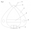
- the Figures 1 to 3 The exemplary cutting device shown comprises a pliers-like device ( Fig.1 ) with two jaws (1) which each have a suitable cutting element (3) at their respective working ends, which are opposite a joint (2). Between the working ends and the joint there is a suitable drive element (4) which can move the two jaws against each other with a suitable force ( Fig.2 ). Two handles (5) with operating elements are conveniently located near the joint to facilitate handling.
- the drive element is conveniently implemented as a double-acting hydraulic cylinder, which is connected to the jaws via joints (6).
- the hydraulic cylinder has an inner diameter of between 70 and 120 mm with a piston rod of between 30 and 70 mm and is pressurized with 150 to 400 bar via an external hydraulic unit.
- the return of the hydraulic cylinder is preferably switched via a rapid motion valve. Cylinder and unit are preferably connected using commercially available plug-in couplings.
- the cutting elements are preferably L-shaped with cutting edges facing each other ( Fig.3 ) to ensure that the chip is completely removed, which prevents the cutting elements from becoming stuck in the wood. For the same reason, the cutting elements are designed so that the cutting edges touch each other over their entire length at the same time. To minimize wear, the cutting elements are preferably made of a highly wear-resistant steel (e.g. Hardox 500) and provided with a crowned cutting edge with a cutting angle of 25 - 30°.
- Hardox 500 highly wear-resistant steel
- the cutting element is attached to the jaw in such a way that the plate forming the horizontal part of the L deviates from the 0 degree position relative to the tangent of the circular arc described by the jaw by approximately 10° outwards, so that a clearance angle ( ⁇ ) of 10° is formed (see Fig.1 ).
Landscapes
- Life Sciences & Earth Sciences (AREA)
- Biodiversity & Conservation Biology (AREA)
- Ecology (AREA)
- Forests & Forestry (AREA)
- Environmental Sciences (AREA)
- Shovels (AREA)
- Crushing And Grinding (AREA)
Description
- Die vorliegende Erfindung betrifft eine Vorrichtung zum grobstückigen Zerspanen von Stubben umfassend mindestens zwei hebelartige, gegeneinander bewegliche, gelenkig miteinander verbundene Zangenbacken, wobei an wenigstens einer der Zangenbacken an dem der anderen Zangenbacke zugewandten Ende ein Schneidorgan ausgebildet sind, wobei die beiden Zangenbacken durch Einwirkung der Kraft einer Antriebsvorrichtung gegeneinander beweglich sind.
- Muss nach der Fällung eines Baumes der verbliebene Stubben (Baumstumpf) entfernt werden, so wird dieser gemäß dem Stand der Technik in der Regel mittels einer Stubbenfräse (
EP000001457106B1 US5623979A ) durch ein schnell laufendes, mit Hartmetallmeißeln bestücktes Fräsrad in situ zerspant. Dieses Verfahren bringt jedoch zahlreiche Nachteile mit sich. - Leistungsstarke Stubbenfräsen sind in der Regel selbstfahrend und mindestens mehrere 100 kg schwer, so dass der Zugang zur Baustelle oft schwierig oder gar ganz unmöglich ist. Selbst kleinere Ausführungen wiegen mindestens 100 kg, sind 70 oder mehr cm breit und verfügen oft nicht über genug Frästiefe, um größere Stubben ganz zu entfernen. Weiterhin sind diese Fräsen, bedingt durch das schnell drehende Fräsrad und den notwendigen leistungsstarken Antriebsmotor, sehr laut, haben durch die teuren und einem hohen Verschleiß ausgesetzten Hartmetallmeißel hohe Wartungskosten und können Steine und Fräsgut mit hoher Geschwindigkeit umherwerfen, so dass es trotz entsprechender Sicherungsmaßnahmen immer wieder zu Unfällen kommt. Darüber hinaus wird das zerspante Holz mit der aufgefrästen Erde vermischt, so dass, wenn dieses nicht vor Ort verwendet werden kann, große Mengen Fräsgut entsorgt werden müssen.
- Alternativ dazu gibt es ein baggergeführtes Rodungsmesser (
DE102008027549B4 ), das die Probleme mit Lärm, Verschleiß und Unfallgefahr vermeidet, indem es ein langsam, aber mit großer Kraft geführtes Schneidorgan verwendet, um die Wurzel zu grobstückig zu zerspanen. Dies ermöglicht es auch, das zerspante Holz von der Erde getrennt aufzusammeln und z.B. einer thermischen Verwertung zuzuführen. Der große Nachteil dieses Systems ist jedoch, dass ein Bagger auf der Baustelle vorhanden sein muss, was meist mit zusätzlichen Kosten verbunden und je nach Zuwegung ganz unmöglich ist. - Auch andere eher im Forst genutzte Verfahren die bohrend (
DE000029622421 U1 sowieEP000002095707B1 DE000003128467A1 sowieDD000000242161A DE000001940446A _) arbeiten sind auf einen Bagger oder andere schwere Baumaschinen angewiesen.GB 2 288 784 A US 10 159 200 B2 - In der
DE 31 28 467 A1 ist eine Vorrichtung mit den eingangs genannten Merkmalen beschrieben. Hier handelt es sich um ein einem Traktor ähnliches Fahrzeug, bei dem das Zerspanen der Stubben über eine hydraulische Zange mit zwei Zangenbacken erfolgt, die an einem Frontladerarm des Fahrzeugs angehängt ist. Es sind zwei Hydraulikzylinder vorgesehen, die beim Ausfahren die Zangenbacken schließen und die im oberen Bereich außen an den Zangenbacken angreifen. Die Zangenbacken sind zwischen zwei Seitenbacken gelagert und mit diesen über Lenker verbunden. Eine derartige Anordnung hat ein sehr hohes Gewicht und kann daher nur über ein Fahrzeug bedient werden. Diese Vorrichtung wird daher nicht als handgeführt im Sinne der vorliegenden Erfindung angesehen. Ein solches Fahrzeug ist schwer, hat einen erheblichen Arbeitsradius und kann beispielsweise im Forstbereich eingesetzt werden, nicht aber in Gärten oder ähnlichen Bereichen, wo der Arbeitsraum für das Fahrzeug nicht vorhanden ist oder die zu entfernenden Stubben mit dem Fahrzeug nicht erreichbar sind. - Die Aufgabe der vorliegenden Erfindung besteht darin, eine Vorrichtung zur Verfügung zu stellen, die diese Nachteile vermeidet, ein langsam, aber mit großer Kraft geführtes Schneidorgan verwendet, um die Wurzel grobstückig zu zerspanen, dabei jedoch durch einen einzelnen Menschen geführt werden kann.
- Diese Aufgabe wird durch eine erfindungsgemäße Vorrichtung mit den Merkmalen des Anspruchs 1 gelöst.
- Die erfindungsgemäße Vorrichtung ist handgeführt und von einer Arbeitsmaschine oder einem Fahrzeug unabhängig ausgebildet.
- Im Rahmen der vorliegenden Erfindung gibt es im Prinzip zwei alternative bevorzugte Varianten, wobei entweder zwei geeignete Schneidorgane gegeneinander oder ein geeignetes Schneidorgan gegen ein geeignetes Halteorgan geführt wird, so dass sich die aufgewendeten Kräfte näherungsweise aufheben.
- Erfindungsgemäß umfasst die Vorrichtung wenigstens eine unmittelbar an den Zangenbacken angreifende Antriebsvorrichtung, welche sich zwischen den beiden Zangenbacken und quer zu einer Verbindungsachse erstreckt, die bei geschlossenen Zangenbacken von einem die beiden Zangenbacken schwenkbar verbindenden Gelenk zu den ein Schneidorgan aufweisenden Enden der Zangenbacken verläuft.
- Vorzugsweise ist die Antriebsvorrichtung ein vorzugsweise doppelt wirkender Hydraulikzylinder.
- Gemäß einer bevorzugten Weiterbildung der Erfindung weist bei der Vorrichtung wenigstens ein Schneidorgan am Schneidende einer der Zangenbacken wenigstens zwei Schneiden auf, die in einem Winkel von 45 ° bis 135 °, vorzugsweise in einem Winkel von 60 ° bis 120 ° zueinander angeordnet sind, wobei das Schneidorgan vorzugsweise etwa L-förmig ausgebildet ist. Während man bei Verwendung nur einer Schneide, Gefahr läuft, dass diese zwar in den Stubben eindringt, sich dann aber verklemmt, kann man bei Verwendung von zwei zueinander im Winkel stehenden Schneiden an einem Schneidorgan einen Span effektiv von dem Stubben abtrennen.
- Gemäß einer bevorzugten Weiterbildung der Erfindung ist wenigstens eine der Schneiden eines der etwa plattenförmigen Schneidorgane an der Zangenbacke so angebracht, dass es einen Freiwinkel α von 0 ° bis 30 ° bildet, vorzugsweise einen Freiwinkel α von 5 ° bis 15 °.
- Vorzugsweise ist weiterhin am Schneidende jeder Zangenbacke jeweils ein Schneidorgan ausgebildet, wobei vorzugsweise beide Schneidorgane gleich geformt und spiegelsymmetrisch zu einer Ebene angeordnet sind, die sich durch die Verbindungsachse erstreckt.
- Nachfolgend wird die Erfindung anhand eines Ausführungsbeispiels unter Bezugnahme auf die beiliegenden Zeichnungen näher erläutert. Dabei zeigen:
-
Figur 1 eine schematisch vereinfachte Ansicht einer erfindungsgemäßen Vorrichtung mit geschlossenen Zangenbacken; -
Figur 2 eine entsprechende Ansicht der Vorrichtung vonFigur 1 mit geöffneten Zangenbacken; -
Figur 3 eine Ansicht bei der man etwa in Achsrichtung der Antriebsvorrichtung (Hydraulikzylinder) auf eine der Zangenbacken schaut und das etwa L-förmige Schneidorgan mit den beiden im Winkel zueinander stehenden Schneiden erkennt. - Das in den
Figuren 1 bis 3 dargestellte beispielhafte Zerspanungsgerät umfasst eine zangenartige Vorrichtung (Fig. 1 ) mit zwei Zangenbacken (1), die an ihren jeweiligen Arbeitsenden, die einem Gelenk (2) gegenüberliegen, jeweils ein geeignetes Schneidorgan (3) aufweisen. Zwischen Arbeitsenden und Gelenk liegt ein geeignetes Antriebsorgan (4), das die beiden Backen mit geeigneter Kraft gegeneinander bewegen kann (Fig. 2 ). Zweckmäßig befinden sich in der Nähe des Gelenks 2 Handgriffe (5) mit Bedienelementen, um die Handhabung zu erleichtern. - Das Antriebsorgan wird zweckmäßig als doppeltwirkender Hydraulikzylinder realisiert, der über Gelenke (6) mit den Backen verbunden ist. Der Hydraulikzylinder weist zweckmäßig einen Innendurchmesser zwischen 70 und 120 mm auf mit einer Kolbenstange zwischen 30 und 70 mm und wird über ein externes Hydraulikaggregat mit 150 bis 400 bar Druck beaufschlagt. Der Rücklauf des Hydraulikzylinders wird vorzugsweise über ein Eilgangventil geschaltet. Zylinder und Aggregat werden vorzugsweise mittels handelsüblicher Steckkupplungen verbunden.
- Die Schneidorgane werden bevorzugt L-förmig mit einander zugewandten Schneidkanten ausgeführt (
Fig. 3 ), um ein vollständiges Abtrennen des Spans zu gewährleisten, wodurch verhindert wird, dass sich die Schneidorgane im Holz festsetzen können. Aus dem gleichen Grund werden die Schneidorgane zweckmäßig so ausgeführt, dass sich die Schneidkanten über ihre ganze Länge zugleich berühren. Um Abnutzung zu minimieren, werden die Schneidorgane vorzugsweise aus einem hoch verschleißfesten Stahl (z.B. Hardox 500) ausgeführt und mit einer ballig geschliffenen Schneide mit 25 - 30° Schneidenwinkel versehen. - Um das Eindringen ins Holz zu erleichtern, ist es vorteilhaft, wenn das Schneidorgan so an der Backe angebracht ist, dass die Platte die den waagerechten Teil des L bildet, von der 0 Grad Position relativ zur Tangente des Kreisbogens den die Backe beschreibt um ca. 10° nach außen abweicht, so dass ein Freiwinkel (α) von 10° gebildet wird (siehe
Fig.1 ).
Claims (5)
- Vorrichtung zum grobstückigen Zerspanen von Stubben umfassend mindestens zwei hebelartige, gegeneinander bewegliche, gelenkig miteinander verbundene Zangenbacken, wobei an wenigstens einer der Zangenbacken an dem der anderen Zangenbacke zugewandten Ende ein Schneidorgan ausgebildet sind, wobei die beiden Zangenbacken durch Einwirkung der Kraft einer Antriebsvorrichtung gegeneinander beweglich sind, wobei die Vorrichtung handgeführt und von einer Arbeitsmaschine oder einem Fahrzeug unabhängig ausgebildet ist, dadurch gekennzeichnet, dass die Vorrichtung wenigstens eine unmittelbar an den Zangenbacken (1) angreifende Antriebsvorrichtung (4) umfasst, welche sich zwischen den beiden Zangenbacken (1) und quer zu einer Verbindungsachse erstreckt, die bei geschlossenen Zangenbacken (1) von einem die beiden Zangenbacken schwenkbar verbindenden Gelenk (2) zu den ein Schneidorgan (3) aufweisenden Enden der Zangenbacken (1) verläuft.
- Vorrichtung nach Anspruch 1, dadurch gekennzeichnet, dass die Antriebsvorrichtung (4) ein vorzugsweise doppelt wirkender Hydraulikzylinder ist.
- Vorrichtung nach einem der Ansprüche 1 oder 2, dadurch gekennzeichnet, dass wenigstens ein Schneidorgan (3) am Schneidende einer der Zangenbacken (1) wenigstens zwei Schneiden aufweist, die in einem Winkel von 45 ° bis 135 °, vorzugsweise in einem Winkel von 60 ° bis 120 ° zueinander angeordnet sind, wobei das Schneidorgan vorzugsweise etwa L-förmig ausgebildet ist.
- Vorrichtung nach einem der Ansprüche 1 bis 3, dadurch gekennzeichnet, dass wenigstens eine der Schneiden eines der etwa plattenförmigen Schneidorgane (3) an der Zangenbacke (1) so angebracht ist, dass es einen Freiwinkel α von 0 ° bis 30 ° bildet, vorzugsweise einen Freiwinkel α von 5 ° bis 15 °.
- Vorrichtung nach einem der Ansprüche 1 bis 4, dadurch gekennzeichnet, dass am Schneidende jeder Zangenbacke (1) jeweils ein Schneidorgan (3) ausgebildet ist, wobei vorzugsweise beide Schneidorgane gleich geformt und spiegelsymmetrisch zu einer Ebene angeordnet sind, die sich durch die Verbindungsachse erstreckt.
Applications Claiming Priority (2)
| Application Number | Priority Date | Filing Date | Title |
|---|---|---|---|
| DE102019111776.3A DE102019111776A1 (de) | 2019-05-07 | 2019-05-07 | Handgeführte Vorrichtung zum Roden von Stubben (Baumstümpfen) |
| PCT/EP2020/061645 WO2020225011A1 (de) | 2019-05-07 | 2020-04-27 | Handgeführte vorrichtung zum roden von stubben |
Publications (2)
| Publication Number | Publication Date |
|---|---|
| EP3965557A1 EP3965557A1 (de) | 2022-03-16 |
| EP3965557B1 true EP3965557B1 (de) | 2024-06-05 |
Family
ID=70471047
Family Applications (1)
| Application Number | Title | Priority Date | Filing Date |
|---|---|---|---|
| EP20722306.6A Active EP3965557B1 (de) | 2019-05-07 | 2020-04-27 | Handgeführte vorrichtung zum roden von stubben |
Country Status (4)
| Country | Link |
|---|---|
| US (1) | US20220201948A1 (de) |
| EP (1) | EP3965557B1 (de) |
| DE (1) | DE102019111776A1 (de) |
| WO (1) | WO2020225011A1 (de) |
Family Cites Families (16)
| Publication number | Priority date | Publication date | Assignee | Title |
|---|---|---|---|---|
| FR1350017A (fr) * | 1962-12-10 | 1964-01-24 | Pelle preneuse | |
| US3376907A (en) * | 1966-06-14 | 1968-04-09 | Hugh E. Mcneal | Tree stump removing apparatus |
| DE1940446A1 (de) | 1969-08-08 | 1971-05-19 | Heinrich Willwacher | Brecheisen fuer das Roden von Stubben |
| DE3128467A1 (de) | 1981-07-18 | 1983-01-27 | Josef 7771 Frickingen Willibald | Verfahren und vorrichtung zum roden von baumstuempfen |
| US4481989A (en) * | 1983-09-20 | 1984-11-13 | Reichhold Chemicals, Inc. | Tree stump extractor |
| DD242161A1 (de) | 1985-11-07 | 1987-01-21 | Meliorationsbau Schwerin Veb | Verfahren und vorrichtung zur baumstumpfrodung und baumstumpfspaltung |
| US5034407A (en) * | 1990-01-16 | 1991-07-23 | Hooser Steven M | Portable stump remover |
| GB9403398D0 (en) * | 1994-02-23 | 1994-04-13 | Designer Tek | Manually carried digger light weight & compact with its own power supply |
| US5497815A (en) | 1994-09-15 | 1996-03-12 | Bowling; John M. | Cutting tooth |
| DE29622421U1 (de) | 1996-12-24 | 1997-02-27 | Technische Universität Dresden, 01069 Dresden | Adapter für Forstpflanzungen |
| US6382277B1 (en) | 2001-04-19 | 2002-05-07 | Sandvik Rock Tools, Inc. | Stump grinding wheel and cutting assemblies therefor |
| GB0324610D0 (en) * | 2003-10-22 | 2003-11-26 | Khan Harmat | Easy dig post holder |
| EP2095707B1 (de) | 2008-02-28 | 2013-02-20 | LASCO Heutechnik GmbH | Fräskopf zum Fräsen von Baumstümpfen |
| DE202008017344U1 (de) | 2008-06-10 | 2009-10-15 | Neidlein, Hartmut | Rodungsmesser |
| FI11070U1 (fi) * | 2015-09-03 | 2015-12-16 | Seppo Jouko Juhani Hassinen | Kantojyrsin |
| FI126476B (fi) * | 2015-11-12 | 2016-12-30 | Ramtec Oy | Kannonnostolaite, järjestelmä ja menetelmä kannon nostamiseksi |
-
2019
- 2019-05-07 DE DE102019111776.3A patent/DE102019111776A1/de active Pending
-
2020
- 2020-04-27 US US17/608,994 patent/US20220201948A1/en not_active Abandoned
- 2020-04-27 EP EP20722306.6A patent/EP3965557B1/de active Active
- 2020-04-27 WO PCT/EP2020/061645 patent/WO2020225011A1/de not_active Ceased
Also Published As
| Publication number | Publication date |
|---|---|
| WO2020225011A1 (de) | 2020-11-12 |
| EP3965557A1 (de) | 2022-03-16 |
| US20220201948A1 (en) | 2022-06-30 |
| DE102019111776A1 (de) | 2020-11-12 |
Similar Documents
| Publication | Publication Date | Title |
|---|---|---|
| EP0618423B1 (de) | Landminen-Raumfahrzeug | |
| AT513118B1 (de) | Seilsäge | |
| EP3091830B1 (de) | Vorrichtung zum entasten lebender bäume | |
| AT507767B1 (de) | Vorrichtung zur mobilen verarbeitung eines gefällten baumes | |
| EP3557977B1 (de) | Wurzelballen-unterschneide- und aushebegerät | |
| DE4205781C2 (de) | Vorrichtung zum Zerkleinern von Schrott | |
| DE102010017888B4 (de) | Vorrichtung zum Besteigen und/oder zur Bearbeitung von Stämmen | |
| EP3965557A1 (de) | Handgeführte vorrichtung zum roden von stubben | |
| DE20116343U1 (de) | Zerkleinerungsmaschine | |
| DE8812484U1 (de) | Vorrichtung zur Bearbeitung von Waldböden | |
| EP0373403B1 (de) | Trenngerät zum Anbau an hydraulische Arbeitsmaschinen | |
| DE69506676T2 (de) | Baumerntemaschine mit Schlaghammer | |
| DE3128467A1 (de) | Verfahren und vorrichtung zum roden von baumstuempfen | |
| EP0814651B1 (de) | Vorrichtung mit einer motorgetriebenen kettensäge zum entästen und fällen von bäumen | |
| DE19507197A1 (de) | Hydraulischer Brennholzspalter | |
| DE10050398C2 (de) | Mehrzweck-Fräsbrecher | |
| EP3118092B1 (de) | Selbstfahrender holzhacker | |
| DE102018128312A1 (de) | Stahlbandschneider | |
| EP1393870A1 (de) | Holzspaltevorrichtung | |
| DE202016104853U1 (de) | Stubbenfräse | |
| DE2410601C3 (de) | Fahrbare Entästungsmaschine für die Forstwirtschaft | |
| DE102012006664B4 (de) | Anbaugerät mit Holzspaltgerät | |
| DE202006001349U1 (de) | Schere für schwere Beanspruchungen, insbesondere Abbruch- und Schneidschere für Altholz | |
| DE4302669A1 (de) | Baumstubbenfräse | |
| AT12798U1 (de) | Holzspalter |
Legal Events
| Date | Code | Title | Description |
|---|---|---|---|
| STAA | Information on the status of an ep patent application or granted ep patent |
Free format text: STATUS: UNKNOWN |
|
| STAA | Information on the status of an ep patent application or granted ep patent |
Free format text: STATUS: THE INTERNATIONAL PUBLICATION HAS BEEN MADE |
|
| PUAI | Public reference made under article 153(3) epc to a published international application that has entered the european phase |
Free format text: ORIGINAL CODE: 0009012 |
|
| STAA | Information on the status of an ep patent application or granted ep patent |
Free format text: STATUS: REQUEST FOR EXAMINATION WAS MADE |
|
| 17P | Request for examination filed |
Effective date: 20211111 |
|
| AK | Designated contracting states |
Kind code of ref document: A1 Designated state(s): AL AT BE BG CH CY CZ DE DK EE ES FI FR GB GR HR HU IE IS IT LI LT LU LV MC MK MT NL NO PL PT RO RS SE SI SK SM TR |
|
| DAV | Request for validation of the european patent (deleted) | ||
| DAX | Request for extension of the european patent (deleted) | ||
| GRAP | Despatch of communication of intention to grant a patent |
Free format text: ORIGINAL CODE: EPIDOSNIGR1 |
|
| STAA | Information on the status of an ep patent application or granted ep patent |
Free format text: STATUS: GRANT OF PATENT IS INTENDED |
|
| RIC1 | Information provided on ipc code assigned before grant |
Ipc: A01G 23/06 20060101AFI20231110BHEP |
|
| INTG | Intention to grant announced |
Effective date: 20231130 |
|
| GRAS | Grant fee paid |
Free format text: ORIGINAL CODE: EPIDOSNIGR3 |
|
| GRAA | (expected) grant |
Free format text: ORIGINAL CODE: 0009210 |
|
| STAA | Information on the status of an ep patent application or granted ep patent |
Free format text: STATUS: THE PATENT HAS BEEN GRANTED |
|
| AK | Designated contracting states |
Kind code of ref document: B1 Designated state(s): AL AT BE BG CH CY CZ DE DK EE ES FI FR GB GR HR HU IE IS IT LI LT LU LV MC MK MT NL NO PL PT RO RS SE SI SK SM TR |
|
| REG | Reference to a national code |
Ref country code: CH Ref legal event code: EP |
|
| REG | Reference to a national code |
Ref country code: DE Ref legal event code: R096 Ref document number: 502020008213 Country of ref document: DE |
|
| REG | Reference to a national code |
Ref country code: IE Ref legal event code: FG4D Free format text: LANGUAGE OF EP DOCUMENT: GERMAN |
|
| REG | Reference to a national code |
Ref country code: LT Ref legal event code: MG9D |
|
| PG25 | Lapsed in a contracting state [announced via postgrant information from national office to epo] |
Ref country code: BG Free format text: LAPSE BECAUSE OF FAILURE TO SUBMIT A TRANSLATION OF THE DESCRIPTION OR TO PAY THE FEE WITHIN THE PRESCRIBED TIME-LIMIT Effective date: 20240605 |
|
| REG | Reference to a national code |
Ref country code: NL Ref legal event code: MP Effective date: 20240605 |
|
| PG25 | Lapsed in a contracting state [announced via postgrant information from national office to epo] |
Ref country code: HR Free format text: LAPSE BECAUSE OF FAILURE TO SUBMIT A TRANSLATION OF THE DESCRIPTION OR TO PAY THE FEE WITHIN THE PRESCRIBED TIME-LIMIT Effective date: 20240605 Ref country code: FI Free format text: LAPSE BECAUSE OF FAILURE TO SUBMIT A TRANSLATION OF THE DESCRIPTION OR TO PAY THE FEE WITHIN THE PRESCRIBED TIME-LIMIT Effective date: 20240605 |
|
| PG25 | Lapsed in a contracting state [announced via postgrant information from national office to epo] |
Ref country code: GR Free format text: LAPSE BECAUSE OF FAILURE TO SUBMIT A TRANSLATION OF THE DESCRIPTION OR TO PAY THE FEE WITHIN THE PRESCRIBED TIME-LIMIT Effective date: 20240906 |
|
| PG25 | Lapsed in a contracting state [announced via postgrant information from national office to epo] |
Ref country code: ES Free format text: LAPSE BECAUSE OF FAILURE TO SUBMIT A TRANSLATION OF THE DESCRIPTION OR TO PAY THE FEE WITHIN THE PRESCRIBED TIME-LIMIT Effective date: 20240605 |
|
| PG25 | Lapsed in a contracting state [announced via postgrant information from national office to epo] |
Ref country code: LV Free format text: LAPSE BECAUSE OF FAILURE TO SUBMIT A TRANSLATION OF THE DESCRIPTION OR TO PAY THE FEE WITHIN THE PRESCRIBED TIME-LIMIT Effective date: 20240605 |
|
| PG25 | Lapsed in a contracting state [announced via postgrant information from national office to epo] |
Ref country code: NO Free format text: LAPSE BECAUSE OF FAILURE TO SUBMIT A TRANSLATION OF THE DESCRIPTION OR TO PAY THE FEE WITHIN THE PRESCRIBED TIME-LIMIT Effective date: 20240905 Ref country code: LV Free format text: LAPSE BECAUSE OF FAILURE TO SUBMIT A TRANSLATION OF THE DESCRIPTION OR TO PAY THE FEE WITHIN THE PRESCRIBED TIME-LIMIT Effective date: 20240605 Ref country code: HR Free format text: LAPSE BECAUSE OF FAILURE TO SUBMIT A TRANSLATION OF THE DESCRIPTION OR TO PAY THE FEE WITHIN THE PRESCRIBED TIME-LIMIT Effective date: 20240605 Ref country code: GR Free format text: LAPSE BECAUSE OF FAILURE TO SUBMIT A TRANSLATION OF THE DESCRIPTION OR TO PAY THE FEE WITHIN THE PRESCRIBED TIME-LIMIT Effective date: 20240906 Ref country code: FI Free format text: LAPSE BECAUSE OF FAILURE TO SUBMIT A TRANSLATION OF THE DESCRIPTION OR TO PAY THE FEE WITHIN THE PRESCRIBED TIME-LIMIT Effective date: 20240605 Ref country code: ES Free format text: LAPSE BECAUSE OF FAILURE TO SUBMIT A TRANSLATION OF THE DESCRIPTION OR TO PAY THE FEE WITHIN THE PRESCRIBED TIME-LIMIT Effective date: 20240605 Ref country code: BG Free format text: LAPSE BECAUSE OF FAILURE TO SUBMIT A TRANSLATION OF THE DESCRIPTION OR TO PAY THE FEE WITHIN THE PRESCRIBED TIME-LIMIT Effective date: 20240605 Ref country code: RS Free format text: LAPSE BECAUSE OF FAILURE TO SUBMIT A TRANSLATION OF THE DESCRIPTION OR TO PAY THE FEE WITHIN THE PRESCRIBED TIME-LIMIT Effective date: 20240905 |
|
| PG25 | Lapsed in a contracting state [announced via postgrant information from national office to epo] |
Ref country code: NL Free format text: LAPSE BECAUSE OF FAILURE TO SUBMIT A TRANSLATION OF THE DESCRIPTION OR TO PAY THE FEE WITHIN THE PRESCRIBED TIME-LIMIT Effective date: 20240605 |
|
| PG25 | Lapsed in a contracting state [announced via postgrant information from national office to epo] |
Ref country code: NL Free format text: LAPSE BECAUSE OF FAILURE TO SUBMIT A TRANSLATION OF THE DESCRIPTION OR TO PAY THE FEE WITHIN THE PRESCRIBED TIME-LIMIT Effective date: 20240605 |
|
| PG25 | Lapsed in a contracting state [announced via postgrant information from national office to epo] |
Ref country code: PT Free format text: LAPSE BECAUSE OF FAILURE TO SUBMIT A TRANSLATION OF THE DESCRIPTION OR TO PAY THE FEE WITHIN THE PRESCRIBED TIME-LIMIT Effective date: 20241007 |
|
| PG25 | Lapsed in a contracting state [announced via postgrant information from national office to epo] |
Ref country code: PT Free format text: LAPSE BECAUSE OF FAILURE TO SUBMIT A TRANSLATION OF THE DESCRIPTION OR TO PAY THE FEE WITHIN THE PRESCRIBED TIME-LIMIT Effective date: 20241007 |
|
| PG25 | Lapsed in a contracting state [announced via postgrant information from national office to epo] |
Ref country code: PL Free format text: LAPSE BECAUSE OF FAILURE TO SUBMIT A TRANSLATION OF THE DESCRIPTION OR TO PAY THE FEE WITHIN THE PRESCRIBED TIME-LIMIT Effective date: 20240605 |
|
| PG25 | Lapsed in a contracting state [announced via postgrant information from national office to epo] |
Ref country code: EE Free format text: LAPSE BECAUSE OF FAILURE TO SUBMIT A TRANSLATION OF THE DESCRIPTION OR TO PAY THE FEE WITHIN THE PRESCRIBED TIME-LIMIT Effective date: 20240605 |
|
| PG25 | Lapsed in a contracting state [announced via postgrant information from national office to epo] |
Ref country code: IS Free format text: LAPSE BECAUSE OF FAILURE TO SUBMIT A TRANSLATION OF THE DESCRIPTION OR TO PAY THE FEE WITHIN THE PRESCRIBED TIME-LIMIT Effective date: 20241005 |
|
| PG25 | Lapsed in a contracting state [announced via postgrant information from national office to epo] |
Ref country code: CZ Free format text: LAPSE BECAUSE OF FAILURE TO SUBMIT A TRANSLATION OF THE DESCRIPTION OR TO PAY THE FEE WITHIN THE PRESCRIBED TIME-LIMIT Effective date: 20240605 |
|
| PG25 | Lapsed in a contracting state [announced via postgrant information from national office to epo] |
Ref country code: SK Free format text: LAPSE BECAUSE OF FAILURE TO SUBMIT A TRANSLATION OF THE DESCRIPTION OR TO PAY THE FEE WITHIN THE PRESCRIBED TIME-LIMIT Effective date: 20240605 Ref country code: RO Free format text: LAPSE BECAUSE OF FAILURE TO SUBMIT A TRANSLATION OF THE DESCRIPTION OR TO PAY THE FEE WITHIN THE PRESCRIBED TIME-LIMIT Effective date: 20240605 |
|
| PG25 | Lapsed in a contracting state [announced via postgrant information from national office to epo] |
Ref country code: SM Free format text: LAPSE BECAUSE OF FAILURE TO SUBMIT A TRANSLATION OF THE DESCRIPTION OR TO PAY THE FEE WITHIN THE PRESCRIBED TIME-LIMIT Effective date: 20240605 |
|
| PG25 | Lapsed in a contracting state [announced via postgrant information from national office to epo] |
Ref country code: SM Free format text: LAPSE BECAUSE OF FAILURE TO SUBMIT A TRANSLATION OF THE DESCRIPTION OR TO PAY THE FEE WITHIN THE PRESCRIBED TIME-LIMIT Effective date: 20240605 Ref country code: SK Free format text: LAPSE BECAUSE OF FAILURE TO SUBMIT A TRANSLATION OF THE DESCRIPTION OR TO PAY THE FEE WITHIN THE PRESCRIBED TIME-LIMIT Effective date: 20240605 Ref country code: RO Free format text: LAPSE BECAUSE OF FAILURE TO SUBMIT A TRANSLATION OF THE DESCRIPTION OR TO PAY THE FEE WITHIN THE PRESCRIBED TIME-LIMIT Effective date: 20240605 Ref country code: PL Free format text: LAPSE BECAUSE OF FAILURE TO SUBMIT A TRANSLATION OF THE DESCRIPTION OR TO PAY THE FEE WITHIN THE PRESCRIBED TIME-LIMIT Effective date: 20240605 Ref country code: IS Free format text: LAPSE BECAUSE OF FAILURE TO SUBMIT A TRANSLATION OF THE DESCRIPTION OR TO PAY THE FEE WITHIN THE PRESCRIBED TIME-LIMIT Effective date: 20241005 Ref country code: EE Free format text: LAPSE BECAUSE OF FAILURE TO SUBMIT A TRANSLATION OF THE DESCRIPTION OR TO PAY THE FEE WITHIN THE PRESCRIBED TIME-LIMIT Effective date: 20240605 Ref country code: CZ Free format text: LAPSE BECAUSE OF FAILURE TO SUBMIT A TRANSLATION OF THE DESCRIPTION OR TO PAY THE FEE WITHIN THE PRESCRIBED TIME-LIMIT Effective date: 20240605 |
|
| PG25 | Lapsed in a contracting state [announced via postgrant information from national office to epo] |
Ref country code: IT Free format text: LAPSE BECAUSE OF FAILURE TO SUBMIT A TRANSLATION OF THE DESCRIPTION OR TO PAY THE FEE WITHIN THE PRESCRIBED TIME-LIMIT Effective date: 20240605 |
|
| REG | Reference to a national code |
Ref country code: DE Ref legal event code: R097 Ref document number: 502020008213 Country of ref document: DE |
|
| PLBE | No opposition filed within time limit |
Free format text: ORIGINAL CODE: 0009261 |
|
| STAA | Information on the status of an ep patent application or granted ep patent |
Free format text: STATUS: NO OPPOSITION FILED WITHIN TIME LIMIT |
|
| PG25 | Lapsed in a contracting state [announced via postgrant information from national office to epo] |
Ref country code: DK Free format text: LAPSE BECAUSE OF FAILURE TO SUBMIT A TRANSLATION OF THE DESCRIPTION OR TO PAY THE FEE WITHIN THE PRESCRIBED TIME-LIMIT Effective date: 20240605 |
|
| 26N | No opposition filed |
Effective date: 20250306 |
|
| PGFP | Annual fee paid to national office [announced via postgrant information from national office to epo] |
Ref country code: DE Payment date: 20250417 Year of fee payment: 6 |
|
| PG25 | Lapsed in a contracting state [announced via postgrant information from national office to epo] |
Ref country code: SE Free format text: LAPSE BECAUSE OF FAILURE TO SUBMIT A TRANSLATION OF THE DESCRIPTION OR TO PAY THE FEE WITHIN THE PRESCRIBED TIME-LIMIT Effective date: 20240605 |
|
| REG | Reference to a national code |
Ref country code: CH Ref legal event code: H13 Free format text: ST27 STATUS EVENT CODE: U-0-0-H10-H13 (AS PROVIDED BY THE NATIONAL OFFICE) Effective date: 20251125 |
|
| PG25 | Lapsed in a contracting state [announced via postgrant information from national office to epo] |
Ref country code: LU Free format text: LAPSE BECAUSE OF NON-PAYMENT OF DUE FEES Effective date: 20250427 |
|
| PG25 | Lapsed in a contracting state [announced via postgrant information from national office to epo] |
Ref country code: MC Free format text: LAPSE BECAUSE OF FAILURE TO SUBMIT A TRANSLATION OF THE DESCRIPTION OR TO PAY THE FEE WITHIN THE PRESCRIBED TIME-LIMIT Effective date: 20240605 |
|
| GBPC | Gb: european patent ceased through non-payment of renewal fee |
Effective date: 20250427 |
|
| REG | Reference to a national code |
Ref country code: BE Ref legal event code: MM Effective date: 20250430 |
|
| PG25 | Lapsed in a contracting state [announced via postgrant information from national office to epo] |
Ref country code: GB Free format text: LAPSE BECAUSE OF NON-PAYMENT OF DUE FEES Effective date: 20250427 |
|
| PG25 | Lapsed in a contracting state [announced via postgrant information from national office to epo] |
Ref country code: FR Free format text: LAPSE BECAUSE OF NON-PAYMENT OF DUE FEES Effective date: 20250430 |
|
| PG25 | Lapsed in a contracting state [announced via postgrant information from national office to epo] |
Ref country code: BE Free format text: LAPSE BECAUSE OF NON-PAYMENT OF DUE FEES Effective date: 20250430 |
|
| PG25 | Lapsed in a contracting state [announced via postgrant information from national office to epo] |
Ref country code: CH Free format text: LAPSE BECAUSE OF NON-PAYMENT OF DUE FEES Effective date: 20250430 |
|
| PG25 | Lapsed in a contracting state [announced via postgrant information from national office to epo] |
Ref country code: IE Free format text: LAPSE BECAUSE OF NON-PAYMENT OF DUE FEES Effective date: 20250427 |