EP3962847B1 - Poste de déroulement - Google Patents
Poste de déroulement Download PDFInfo
- Publication number
- EP3962847B1 EP3962847B1 EP20705959.3A EP20705959A EP3962847B1 EP 3962847 B1 EP3962847 B1 EP 3962847B1 EP 20705959 A EP20705959 A EP 20705959A EP 3962847 B1 EP3962847 B1 EP 3962847B1
- Authority
- EP
- European Patent Office
- Prior art keywords
- unwinding device
- running
- primary
- transport apparatus
- unwinding
- Prior art date
- Legal status (The legal status is an assumption and is not a legal conclusion. Google has not performed a legal analysis and makes no representation as to the accuracy of the status listed.)
- Active
Links
Images

Classifications
-
- B—PERFORMING OPERATIONS; TRANSPORTING
- B65—CONVEYING; PACKING; STORING; HANDLING THIN OR FILAMENTARY MATERIAL
- B65H—HANDLING THIN OR FILAMENTARY MATERIAL, e.g. SHEETS, WEBS, CABLES
- B65H19/00—Changing the web roll
- B65H19/10—Changing the web roll in unwinding mechanisms or in connection with unwinding operations
- B65H19/12—Lifting, transporting, or inserting the web roll; Removing empty core
- B65H19/126—Lifting, transporting, or inserting the web roll; Removing empty core with both-ends supporting arrangements
-
- B—PERFORMING OPERATIONS; TRANSPORTING
- B65—CONVEYING; PACKING; STORING; HANDLING THIN OR FILAMENTARY MATERIAL
- B65H—HANDLING THIN OR FILAMENTARY MATERIAL, e.g. SHEETS, WEBS, CABLES
- B65H16/00—Unwinding, paying-out webs
- B65H16/02—Supporting web roll
- B65H16/06—Supporting web roll both-ends type
-
- B—PERFORMING OPERATIONS; TRANSPORTING
- B65—CONVEYING; PACKING; STORING; HANDLING THIN OR FILAMENTARY MATERIAL
- B65H—HANDLING THIN OR FILAMENTARY MATERIAL, e.g. SHEETS, WEBS, CABLES
- B65H16/00—Unwinding, paying-out webs
- B65H16/10—Arrangements for effecting positive rotation of web roll
- B65H16/103—Arrangements for effecting positive rotation of web roll in which power is applied to web-roll spindle
-
- B—PERFORMING OPERATIONS; TRANSPORTING
- B65—CONVEYING; PACKING; STORING; HANDLING THIN OR FILAMENTARY MATERIAL
- B65H—HANDLING THIN OR FILAMENTARY MATERIAL, e.g. SHEETS, WEBS, CABLES
- B65H19/00—Changing the web roll
- B65H19/10—Changing the web roll in unwinding mechanisms or in connection with unwinding operations
- B65H19/18—Attaching, e.g. pasting, the replacement web to the expiring web
- B65H19/1805—Flying splicing, i.e. the expiring web moving during splicing contact
- B65H19/1826—Flying splicing, i.e. the expiring web moving during splicing contact taking place at a distance from the replacement roll
- B65H19/1836—Flying splicing, i.e. the expiring web moving during splicing contact taking place at a distance from the replacement roll the replacement web being accelerated or running prior to splicing contact
-
- B—PERFORMING OPERATIONS; TRANSPORTING
- B65—CONVEYING; PACKING; STORING; HANDLING THIN OR FILAMENTARY MATERIAL
- B65H—HANDLING THIN OR FILAMENTARY MATERIAL, e.g. SHEETS, WEBS, CABLES
- B65H19/00—Changing the web roll
- B65H19/10—Changing the web roll in unwinding mechanisms or in connection with unwinding operations
- B65H19/18—Attaching, e.g. pasting, the replacement web to the expiring web
- B65H19/1857—Support arrangement of web rolls
- B65H19/1863—Support arrangement of web rolls with translatory or arcuated movement of the roll supports
-
- B—PERFORMING OPERATIONS; TRANSPORTING
- B65—CONVEYING; PACKING; STORING; HANDLING THIN OR FILAMENTARY MATERIAL
- B65H—HANDLING THIN OR FILAMENTARY MATERIAL, e.g. SHEETS, WEBS, CABLES
- B65H2301/00—Handling processes for sheets or webs
- B65H2301/40—Type of handling process
- B65H2301/41—Winding, unwinding
- B65H2301/413—Supporting web roll
- B65H2301/4136—Mounting arrangements not otherwise provided for
- B65H2301/41361—Mounting arrangements not otherwise provided for sequentially used roll supports for the same web roll
-
- B—PERFORMING OPERATIONS; TRANSPORTING
- B65—CONVEYING; PACKING; STORING; HANDLING THIN OR FILAMENTARY MATERIAL
- B65H—HANDLING THIN OR FILAMENTARY MATERIAL, e.g. SHEETS, WEBS, CABLES
- B65H2301/00—Handling processes for sheets or webs
- B65H2301/40—Type of handling process
- B65H2301/41—Winding, unwinding
- B65H2301/417—Handling or changing web rolls
- B65H2301/4171—Handling web roll
- B65H2301/4173—Handling web roll by central portion, e.g. gripping central portion
- B65H2301/41734—Handling web roll by central portion, e.g. gripping central portion involving rail
-
- B—PERFORMING OPERATIONS; TRANSPORTING
- B65—CONVEYING; PACKING; STORING; HANDLING THIN OR FILAMENTARY MATERIAL
- B65H—HANDLING THIN OR FILAMENTARY MATERIAL, e.g. SHEETS, WEBS, CABLES
- B65H2511/00—Dimensions; Position; Numbers; Identification; Occurrences
- B65H2511/10—Size; Dimensions
- B65H2511/12—Width
-
- B—PERFORMING OPERATIONS; TRANSPORTING
- B65—CONVEYING; PACKING; STORING; HANDLING THIN OR FILAMENTARY MATERIAL
- B65H—HANDLING THIN OR FILAMENTARY MATERIAL, e.g. SHEETS, WEBS, CABLES
- B65H2801/00—Application field
- B65H2801/84—Paper-making machines
Definitions
- the invention relates to a device for unwinding a material web, in particular a paper or cardboard web, from a winding roll for a subsequent machine unit for processing the material web, the axle journals of which are mounted in axle journal bearings with a rotatable outer ring, with a primary unwinding device, a secondary unwinding device, a transport device running between the primary and secondary unwinding devices and an gluing and separating device, wherein the primary and secondary unwinding devices and the transport device for moving the winding roll from the primary to the secondary unwinding device each have two running surfaces running parallel to one another and coming into contact with corresponding counter surfaces of the outer rings of the axle journal bearings, the axial position of the running surfaces of the primary and secondary unwinding devices is adjustable and the running surfaces of the primary and secondary unwinding devices and the corresponding counter surfaces of the outer rings have a shape that axially guides the respective outer ring.
- Unwinding stations of the type discussed here are well known. They are used for the continuous unwinding of a material web from a winding reel and are installed upstream of a machine for processing the material web, such as a coating machine or a calender.
- a known unwinding station comprises a primary and a secondary unwinding device, which serve to guide a winding roll.
- a full winding roll is initially guided by the primary unwinding device during the unwinding of the material web. Once the winding roll reaches a desired diameter, it is transferred from the primary to the secondary unwinding device.
- a new, full reel is then fed to the primary unwinding device, and the material web wound on it is joined to the reel guided by the secondary unwinding device before the reel is completely unwound.
- a gluing device is provided, which often has a gluing roller pivoting about an axis, via which the reel guided by the secondary unwinding device is connected to the reel - in The material web is then guided to the subsequent material web processing machine (viewed in the direction of travel of the material web).
- the adhesive roller is pivoted and pressed against the winding roll guided by the primary unwinding device.
- the material web running off the winding roll guided by the secondary unwinding device is severed by a cutting device.
- Carrier roll winding machines have two driven carrier rolls on which the winding rolls rest next to each other with their cores aligned during winding.
- the carrier roll winding machines have a roll ejection device that ejects a set of finished wound rolls from the roller bed formed by the two carrier rolls during a roll change. The finished set of wound rolls is then pushed by the ejection device over the top of a carrier roll onto a lowering platform.
- swivel arms For transport from the primary to the secondary unwinding station, for example, swivel arms that can be pivoted around an axis are used. These arms engage both sides of the winding roll and transfer it to the secondary unwinding device by means of a swivel movement.
- axle journals of the winding roll on several rails arranged one behind the other of the primary and secondary unwinding devices and the transport device.
- the primary and secondary unwinding devices as well as the transport device with their rails are axially adjustable, which is relatively complex.
- the object of the invention is therefore to reduce the effort required for unwinding the material web.
- the transport of the winding roll is simplified if the running surfaces of the primary and secondary unwinding devices and the transport device are horizontal or slightly inclined in the transport direction.
- the horizontal movement of the winding roll on the running surfaces is usually supported by linear slides.
- the outer rings of the axle journal bearings of the winding roll in the primary and secondary unwinding devices are each guided on two parallel guide rails. have a complementary circumferential groove into which the corresponding guide rail of the primary and secondary unwinding device protrudes.
- the running surfaces of the transport device are also designed as running rails that project into the circumferential groove of the corresponding outer ring, whereby the running rails of the transport device, however, have a significantly smaller width than the running rails of the primary and/or secondary unwinding device.
- the outer rings of the journal bearings each have a circumferential ring that projects into a complementary groove of the corresponding running surface of the primary and/or secondary rolling device.
- the circumferential ring of the outer rings of the journal bearings should each protrude into a groove of the corresponding running surface of the transport device, which, however, has a significantly greater width than the grooves of the corresponding running surface of the primary and/or secondary rolling device.
- the running surfaces of the transport device are located below the running surfaces of the primary and/or secondary unwinding device.
- a wide running surface of the transport device additionally ensures the rolling of the outer rings of the axle journal bearings regardless of their possible axial position.
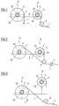
- a material web 1 is unwound from the full winding roll 2 in the primary unwinding device 5 by a first drive.
- the winding roll 3 Simultaneously with the still full winding roll 2 (full reel, "mother roll"), the winding roll 3, which is essentially already unwound, is unwound in the secondary unwinding device 6 by a second drive to the end of a material web 1.
- the power of the second drive is dimensioned such that its drive motor is just sufficient to generate a small torque to enable the remaining unwinding of the material web 1 from the winding roll 3 in the secondary unwinding device 6.
- the first drive is dimensioned such that its torque is sufficient to unwind the material web 1 even from the still full winding roll 2, which can have a diameter of, for example, 3500 mm and more.
- the drives can be stationary or movable.
- Material web 1 can be deflected via one or more deflection rollers 9 to stabilize the web run.
- the two axle journals 17 of the winding roll 2, 3, 4 each have an axle journal bearing 18 with an outer ring 10 rotatable around the axle journal 17, in particular in the form of a rolling bearing.
- winding roll 2 is Figure 4 into the secondary unwinding device 6. This winding roll 2 is then completely unwound in the secondary unwinding device 6 in which the winding roll 3 was originally located.
- Figure 5 A new winding roll 4 is placed into the primary unwinding device 5, in which the winding roll 2 had previously been located. Subsequently, the same unwinding processes take place as previously described.
- the web tension is controlled throughout the entire process, which counteracts winding errors.
- the material web 1 is divided into several individual webs of adjustable width by means of a known, not shown Cutting section. These individual webs are then wound onto the core set located in a winding bed to form shipping rolls.
- the winding roll 2, 3 is axially fixed in a fixed bearing of the primary 5 or secondary unwinding device 6. This prevents axial displacement of the material web 1 during unwinding and thus also during the cutting of the web and the rewinding of the partial webs.
- axle journals 17 or their axle journal bearings 18 are each mounted in a receiving fork or similar.
- the axial position of the bearing, in particular of each guide rail of both unwinding devices 5, 6, can be axially adjusted separately to adapt to the conditions of the respective winding roll 2, 3.
- the primary unwinding device 5 and the secondary unwinding device 6 are connected to one another via a transport device 8, wherein the transport device 8 for the outer rings 10 of the axle journal bearings 18 of the winding roll 2, 3 has two running surfaces 11 running parallel to one another and horizontally between the primary 5 and the secondary unwinding device 6.
- the outer rings 10 of the axle journal bearings 18 can be mounted within the rolling devices 5,6 on the guide rails 12 and within the Transport device 8 slides or preferably rolls on the running surfaces 11, which significantly simplifies the transfer of the winding roll 2 from the primary unwinding device 5 to the secondary unwinding device 6.
- the transport device 8 stands firmly on a foundation.
- the running surfaces 11 of the transport device 8 are considerably wider than the guide rails of the unwinding devices 5,6.
- both adjacent areas of the outer rings 10 located next to the circumferential groove 13 act as contact or counter surfaces for the running surface 11 of the transport device 8 and the running surface 11 is arranged below the upper side of the guide rail.
- the running surfaces 11 of the transport device 8 should be wide enough so that the contact or counter surface 14 of the outer rings 10 is sufficiently large for secure support of the winding roll 2,3, regardless of the axial position of the running rails of the unwinding devices 5,6.
- Figure 7 a design in which the running surfaces 11 of the transport device 8 are also formed by guide rails that protrude into the circumferential groove 13 of the outer rings 10.
- the guide rails of the transport device 8 are considerably narrower than those of the unwinding devices 5, 6, so that the guide rails of the transport devices 8 have a sufficiently large axial play within the circumferential groove 13 for the axial adjustment of the winding roll 2, 3.
- the outer rings 10 in the Figures 9 and 10 a circumferential ring 14 each, which projects into a corresponding complementary groove 15 of the running surfaces 12 of the rolling devices 5,6 and thus ensures the necessary axial guidance.
- the running surface 11 of the transport device 8 also has a groove 16 into which the circumferential ring 14 of the respective outer ring 10 projects.
- the groove 16 of the transport device 8 is considerably wider than the groove 15 of the unwinding devices 5, 6, which ensures the necessary axial clearance in the area of the transport device 8.
- Figure 10 a possible further training of Figure 9 , wherein the running surface 11 of the transport device 8 has no axial limitation similar to that in Figure 8 shown example.
Landscapes
- Replacement Of Web Rolls (AREA)
- Unwinding Webs (AREA)
Claims (8)
- Dispositif de déroulement d'une bande de matériau (1), en particulier d'une bande de papier ou de carton, comprenant un rouleau d'enroulement (2, 3), pour une unité de machine suivante destinée à usiner la bande de matériau (1), dont les tourillons (17) sont montés dans des paliers (18) de tourillon avec une bague extérieure (10) rotative, avec un système de déroulement primaire (5), un système de déroulement secondaire (6), un système de transport (8) s'étendant entre le système de déroulement primaire (5) et le système de déroulement secondaire (6) ainsi qu'un dispositif de collage et de séparation (7), le système de transport (8) étant fixe, caractérisé en ce que le système de déroulement primaire (5), le système de déroulement secondaire (6) et le système de transport (8) comportent chacun, pour le déplacement du rouleau d'enroulement (2, 3) depuis le système de déroulement primaire (5) vers le système de déroulement secondaire (6), deux surfaces de roulement (11, 12) s'étendant parallèlement l'une à l'autre et venant en contact avec des contre-surfaces correspondantes des bagues extérieures (10) des paliers (18) de tourillon, la position axiale des surfaces de roulement (12) du système de déroulement primaire (5) et du système de déroulement secondaire (6) peut être réglée et les surfaces de roulement (12) du système de déroulement primaire (5) et du système de déroulement secondaire (6) ainsi que les contre-surfaces correspondantes des bagues extérieures (10) possèdent une forme guidant axialement la bague extérieure (10) respective,
et les surfaces de roulement (11) du système de transport (8) offrent au moins un espace libre axial correspondant à l'étendue du réglage axial des surfaces de roulement (12) du système de déroulement primaire (5) et du système de déroulement secondaire (6). - Dispositif selon la revendication 1, caractérisé en ce que les surfaces de roulement (11, 12) du système de déroulement primaire (5), du système de déroulement secondaire (6) ainsi que du système de transport (8) s'étendent au moins sensiblement horizontalement.
- Dispositif selon la revendication 1 ou 2, caractérisé en ce que les surfaces de roulement (12) du système de déroulement primaire (5) et du système de déroulement secondaire (6) sont réalisées comme des rails de roulement, qui dépassent à l'intérieur d'une rainure périphérique (13) complémentaire de la bague extérieure (10) correspondante.
- Dispositif selon la revendication 3, caractérisé en ce que les surfaces de roulement (11) du système de transport (8) sont réalisées comme des rails de roulement, qui dépassent à l'intérieur de la rainure périphérique (13) de la bague extérieure (10) correspondante, les rails de roulement du système de transport (8) possédant une largeur sensiblement inférieure à celle des rails de roulement du système de déroulement primaire (5) et/ou du système de déroulement secondaire (6).
- Dispositif selon la revendication 1 ou 2, caractérisé en ce que les bagues extérieures (10) possèdent chacune une bague périphérique (14) qui dépasse à l'intérieur d'une rainure (15) complémentaire de la surface de roulement (12) correspondante du système de déroulement primaire (5) et du système de déroulement secondaire (6).
- Dispositif selon la revendication 5, caractérisé en ce que la bague périphérique (14) des bagues extérieures (10) dépasse respectivement dans une rainure (16) de la surface de roulement (11) correspondante du système de transport (8), lesdites rainures (16) possédant une largeur sensiblement plus grande que celle des rainures (15) de la surface de roulement (12) correspondante du système de déroulement primaire (5) et du système de déroulement secondaire (6).
- Dispositif selon la revendication 1 ou 2, caractérisé en ce que les contre-surfaces des bagues extérieures (10) pour les surfaces de roulement (11) du système de transport (8) sont différentes des surfaces de roulement (12) correspondantes du système de déroulement primaire (5) et du système de déroulement secondaire (6).
- Dispositif selon la revendication 7, caractérisé en ce que les surfaces de roulement (11) du système de transport (8) sont situées sous les surfaces de roulement (12) du système de déroulement primaire (5) et du système de déroulement secondaire (6).
Applications Claiming Priority (2)
| Application Number | Priority Date | Filing Date | Title |
|---|---|---|---|
| DE102019111475.6A DE102019111475B4 (de) | 2019-05-03 | 2019-05-03 | Abrollstation |
| PCT/EP2020/054165 WO2020224818A1 (fr) | 2019-05-03 | 2020-02-18 | Poste de déroulement |
Publications (3)
| Publication Number | Publication Date |
|---|---|
| EP3962847A1 EP3962847A1 (fr) | 2022-03-09 |
| EP3962847C0 EP3962847C0 (fr) | 2025-06-18 |
| EP3962847B1 true EP3962847B1 (fr) | 2025-06-18 |
Family
ID=69630319
Family Applications (1)
| Application Number | Title | Priority Date | Filing Date |
|---|---|---|---|
| EP20705959.3A Active EP3962847B1 (fr) | 2019-05-03 | 2020-02-18 | Poste de déroulement |
Country Status (4)
| Country | Link |
|---|---|
| EP (1) | EP3962847B1 (fr) |
| CN (1) | CN114007966B (fr) |
| DE (1) | DE102019111475B4 (fr) |
| WO (1) | WO2020224818A1 (fr) |
Citations (2)
| Publication number | Priority date | Publication date | Assignee | Title |
|---|---|---|---|---|
| GB979808A (en) * | 1961-07-08 | 1965-01-06 | Joseph Eck & Sohne | Machine for the uninterrupted unwinding of a web of material |
| DE112009002420T5 (de) * | 2008-09-29 | 2011-07-28 | Metso Paper, Inc. | Verfahren und Vorrichtung zum Absenken und/oder Anheben einer Wickelwelle |
Family Cites Families (6)
| Publication number | Priority date | Publication date | Assignee | Title |
|---|---|---|---|---|
| DE1574632B1 (de) * | 1968-01-09 | 1971-02-25 | Zum Bruderhaus Gmbh Maschf | Vorrichtung zum ununterbrochenen Abwickeln einer Bahn,insbesondere einer Papierbahn |
| DE4302345A1 (de) * | 1993-01-28 | 1994-08-04 | Kampf Gmbh & Co Maschf | Rollenschneidmaschine zum Aufwickeln von vorzugsweise schmalen Materialbahnen, insbesondere aus Kunststoff, Papier oder dergleichen in Einzelwickelstationen |
| IT1264215B1 (it) * | 1993-09-14 | 1996-09-23 | Gd Spa | Dispositivo di prelievo e trasferimento di bobine da un magazzino ad una unita' di svolgitura. |
| RU2008128352A (ru) * | 2005-12-15 | 2010-01-20 | Ерликон Текстиле Гмбх Унд Ко. Кг (De) | Намоточное устройство |
| DE102005000187A1 (de) | 2005-12-16 | 2007-06-21 | Voith Patent Gmbh | Vorrichtung und Verfahren zum Abwickeln einer Materialbahn |
| DE102016211582A1 (de) | 2016-06-28 | 2017-03-23 | Voith Patent Gmbh | Abrollstation |
-
2019
- 2019-05-03 DE DE102019111475.6A patent/DE102019111475B4/de not_active Withdrawn - After Issue
-
2020
- 2020-02-18 WO PCT/EP2020/054165 patent/WO2020224818A1/fr not_active Ceased
- 2020-02-18 CN CN202080033075.3A patent/CN114007966B/zh active Active
- 2020-02-18 EP EP20705959.3A patent/EP3962847B1/fr active Active
Patent Citations (2)
| Publication number | Priority date | Publication date | Assignee | Title |
|---|---|---|---|---|
| GB979808A (en) * | 1961-07-08 | 1965-01-06 | Joseph Eck & Sohne | Machine for the uninterrupted unwinding of a web of material |
| DE112009002420T5 (de) * | 2008-09-29 | 2011-07-28 | Metso Paper, Inc. | Verfahren und Vorrichtung zum Absenken und/oder Anheben einer Wickelwelle |
Also Published As
| Publication number | Publication date |
|---|---|
| WO2020224818A8 (fr) | 2021-12-30 |
| EP3962847C0 (fr) | 2025-06-18 |
| DE102019111475B4 (de) | 2022-01-13 |
| CN114007966B (zh) | 2024-04-05 |
| CN114007966A (zh) | 2022-02-01 |
| WO2020224818A1 (fr) | 2020-11-12 |
| EP3962847A1 (fr) | 2022-03-09 |
| DE102019111475A1 (de) | 2020-11-05 |
Similar Documents
| Publication | Publication Date | Title |
|---|---|---|
| DE4415324C2 (de) | Vorrichtung zum Aufwickeln einer kontinuierlich zulaufenden Bahn, insbesondere Papierbahn | |
| EP0664267A2 (fr) | Enrouleur avec tambour de support pour une machine de fabrication de papier | |
| EP0145029B1 (fr) | Dispositif d'enroulement ou de déroulement à plusieurs arbres en cascade | |
| EP2313335B1 (fr) | Dispositif et procédé pour enrouler et/ou dérouler des bandes de matériau | |
| DE60009917T2 (de) | Verfahren zum kontinuierlichen aufwickeln von papier und wickler | |
| EP2184243B1 (fr) | Procédé destiné à enrouler des bandes de matériau et dispositif destiné à l'exécution du procédé | |
| AT511278B1 (de) | Verfahren in zusammenhang mit einer rollenschneidmaschine für eine faserbahn | |
| EP3962847B1 (fr) | Poste de déroulement | |
| EP1454858A1 (fr) | Enrouleuse | |
| EP3962848B1 (fr) | Poste de déroulement | |
| EP0886620B1 (fr) | Dispositif d'enroulement continu de bandes de papier coupees longitudinalement avec changement automatique des rouleaux a vitesse de la machine | |
| DE102011116308A1 (de) | Doppeltragwalzenroller | |
| EP1657194B1 (fr) | Dispositif d'enroulage de bobines et procédé pour l'enroulement de bobines | |
| EP2601120B1 (fr) | Dispositif pour l'enroulement de matériaux en forme de bande à rouler | |
| DE19720174B4 (de) | Kalander | |
| DE102009004815B4 (de) | Herstellungs- und/oder Behandlungslinie für eine Faserbahn | |
| EP1657193B1 (fr) | Dispositif d'enroulage de bobines et procédé pour l'enroulement de bobines | |
| AT511483B1 (de) | Wickelvorrichtung für eine faserbahn und verfahren zum wickeln von rollen von teilbahnen in der wickelvorrichtung | |
| DE60015144T2 (de) | Verfahren zum kontinuierlichen aufwickeln von papier und wickler | |
| DE112011103575T5 (de) | Vorrichtung zum Wickeln von Faserbahnen, insbesondere Papier- und Kartonbahnen | |
| EP3966142A1 (fr) | Déroulement de bande de matériau | |
| DE9218131U1 (de) | Vorrichtung zum Zuführen von rollenförmigem Material zu einer Klebevorbereitungsstation |
Legal Events
| Date | Code | Title | Description |
|---|---|---|---|
| STAA | Information on the status of an ep patent application or granted ep patent |
Free format text: STATUS: UNKNOWN |
|
| STAA | Information on the status of an ep patent application or granted ep patent |
Free format text: STATUS: THE INTERNATIONAL PUBLICATION HAS BEEN MADE |
|
| PUAI | Public reference made under article 153(3) epc to a published international application that has entered the european phase |
Free format text: ORIGINAL CODE: 0009012 |
|
| STAA | Information on the status of an ep patent application or granted ep patent |
Free format text: STATUS: REQUEST FOR EXAMINATION WAS MADE |
|
| 17P | Request for examination filed |
Effective date: 20211203 |
|
| AK | Designated contracting states |
Kind code of ref document: A1 Designated state(s): AL AT BE BG CH CY CZ DE DK EE ES FI FR GB GR HR HU IE IS IT LI LT LU LV MC MK MT NL NO PL PT RO RS SE SI SK SM TR |
|
| DAV | Request for validation of the european patent (deleted) | ||
| DAX | Request for extension of the european patent (deleted) | ||
| GRAP | Despatch of communication of intention to grant a patent |
Free format text: ORIGINAL CODE: EPIDOSNIGR1 |
|
| STAA | Information on the status of an ep patent application or granted ep patent |
Free format text: STATUS: GRANT OF PATENT IS INTENDED |
|
| INTG | Intention to grant announced |
Effective date: 20250122 |
|
| GRAS | Grant fee paid |
Free format text: ORIGINAL CODE: EPIDOSNIGR3 |
|
| GRAA | (expected) grant |
Free format text: ORIGINAL CODE: 0009210 |
|
| STAA | Information on the status of an ep patent application or granted ep patent |
Free format text: STATUS: THE PATENT HAS BEEN GRANTED |
|
| AK | Designated contracting states |
Kind code of ref document: B1 Designated state(s): AL AT BE BG CH CY CZ DE DK EE ES FI FR GB GR HR HU IE IS IT LI LT LU LV MC MK MT NL NO PL PT RO RS SE SI SK SM TR |
|
| REG | Reference to a national code |
Ref country code: GB Ref legal event code: FG4D Free format text: NOT ENGLISH |
|
| REG | Reference to a national code |
Ref country code: CH Ref legal event code: EP |
|
| REG | Reference to a national code |
Ref country code: DE Ref legal event code: R096 Ref document number: 502020011235 Country of ref document: DE |
|
| REG | Reference to a national code |
Ref country code: CH Ref legal event code: EP |
|
| REG | Reference to a national code |
Ref country code: IE Ref legal event code: FG4D Free format text: LANGUAGE OF EP DOCUMENT: GERMAN |
|
| U01 | Request for unitary effect filed |
Effective date: 20250717 |
|
| U07 | Unitary effect registered |
Designated state(s): AT BE BG DE DK EE FI FR IT LT LU LV MT NL PT RO SE SI Effective date: 20250723 |
|
| PG25 | Lapsed in a contracting state [announced via postgrant information from national office to epo] |
Ref country code: NO Free format text: LAPSE BECAUSE OF FAILURE TO SUBMIT A TRANSLATION OF THE DESCRIPTION OR TO PAY THE FEE WITHIN THE PRESCRIBED TIME-LIMIT Effective date: 20250918 Ref country code: GR Free format text: LAPSE BECAUSE OF FAILURE TO SUBMIT A TRANSLATION OF THE DESCRIPTION OR TO PAY THE FEE WITHIN THE PRESCRIBED TIME-LIMIT Effective date: 20250919 |
|
| PG25 | Lapsed in a contracting state [announced via postgrant information from national office to epo] |
Ref country code: HR Free format text: LAPSE BECAUSE OF FAILURE TO SUBMIT A TRANSLATION OF THE DESCRIPTION OR TO PAY THE FEE WITHIN THE PRESCRIBED TIME-LIMIT Effective date: 20250618 |
|
| PG25 | Lapsed in a contracting state [announced via postgrant information from national office to epo] |
Ref country code: RS Free format text: LAPSE BECAUSE OF FAILURE TO SUBMIT A TRANSLATION OF THE DESCRIPTION OR TO PAY THE FEE WITHIN THE PRESCRIBED TIME-LIMIT Effective date: 20250918 |
|
| PG25 | Lapsed in a contracting state [announced via postgrant information from national office to epo] |
Ref country code: IS Free format text: LAPSE BECAUSE OF FAILURE TO SUBMIT A TRANSLATION OF THE DESCRIPTION OR TO PAY THE FEE WITHIN THE PRESCRIBED TIME-LIMIT Effective date: 20251018 |
|
| PG25 | Lapsed in a contracting state [announced via postgrant information from national office to epo] |
Ref country code: SM Free format text: LAPSE BECAUSE OF FAILURE TO SUBMIT A TRANSLATION OF THE DESCRIPTION OR TO PAY THE FEE WITHIN THE PRESCRIBED TIME-LIMIT Effective date: 20250618 |
|
| PG25 | Lapsed in a contracting state [announced via postgrant information from national office to epo] |
Ref country code: CZ Free format text: LAPSE BECAUSE OF FAILURE TO SUBMIT A TRANSLATION OF THE DESCRIPTION OR TO PAY THE FEE WITHIN THE PRESCRIBED TIME-LIMIT Effective date: 20250618 |
|
| PG25 | Lapsed in a contracting state [announced via postgrant information from national office to epo] |
Ref country code: PL Free format text: LAPSE BECAUSE OF FAILURE TO SUBMIT A TRANSLATION OF THE DESCRIPTION OR TO PAY THE FEE WITHIN THE PRESCRIBED TIME-LIMIT Effective date: 20250618 |
|
| PG25 | Lapsed in a contracting state [announced via postgrant information from national office to epo] |
Ref country code: SK Free format text: LAPSE BECAUSE OF FAILURE TO SUBMIT A TRANSLATION OF THE DESCRIPTION OR TO PAY THE FEE WITHIN THE PRESCRIBED TIME-LIMIT Effective date: 20250618 |
|
| PG25 | Lapsed in a contracting state [announced via postgrant information from national office to epo] |
Ref country code: ES Free format text: LAPSE BECAUSE OF FAILURE TO SUBMIT A TRANSLATION OF THE DESCRIPTION OR TO PAY THE FEE WITHIN THE PRESCRIBED TIME-LIMIT Effective date: 20250618 |
|
| U20 | Renewal fee for the european patent with unitary effect paid |
Year of fee payment: 7 Effective date: 20260302 |
|
| PLBE | No opposition filed within time limit |
Free format text: ORIGINAL CODE: 0009261 |
|
| STAA | Information on the status of an ep patent application or granted ep patent |
Free format text: STATUS: NO OPPOSITION FILED WITHIN TIME LIMIT |