EP3961757B1 - Sekundärbatterie mit wasserfreiem elektrolyt - Google Patents
Sekundärbatterie mit wasserfreiem elektrolyt Download PDFInfo
- Publication number
- EP3961757B1 EP3961757B1 EP20794428.1A EP20794428A EP3961757B1 EP 3961757 B1 EP3961757 B1 EP 3961757B1 EP 20794428 A EP20794428 A EP 20794428A EP 3961757 B1 EP3961757 B1 EP 3961757B1
- Authority
- EP
- European Patent Office
- Prior art keywords
- negative electrode
- electrode mixture
- mixture layer
- graphite particles
- adjacent
- Prior art date
- Legal status (The legal status is an assumption and is not a legal conclusion. Google has not performed a legal analysis and makes no representation as to the accuracy of the status listed.)
- Active
Links
Images
Classifications
-
- H—ELECTRICITY
- H01—ELECTRIC ELEMENTS
- H01M—PROCESSES OR MEANS, e.g. BATTERIES, FOR THE DIRECT CONVERSION OF CHEMICAL ENERGY INTO ELECTRICAL ENERGY
- H01M4/00—Electrodes
- H01M4/02—Electrodes composed of, or comprising, active material
- H01M4/62—Selection of inactive substances as ingredients for active masses, e.g. binders, fillers
- H01M4/621—Binders
-
- H—ELECTRICITY
- H01—ELECTRIC ELEMENTS
- H01M—PROCESSES OR MEANS, e.g. BATTERIES, FOR THE DIRECT CONVERSION OF CHEMICAL ENERGY INTO ELECTRICAL ENERGY
- H01M4/00—Electrodes
- H01M4/02—Electrodes composed of, or comprising, active material
- H01M4/36—Selection of substances as active materials, active masses, active liquids
- H01M4/58—Selection of substances as active materials, active masses, active liquids of inorganic compounds other than oxides or hydroxides, e.g. sulfides, selenides, tellurides, halogenides or LiCoFy; of polyanionic structures, e.g. phosphates, silicates or borates
- H01M4/583—Carbonaceous material, e.g. graphite-intercalation compounds or CFx
-
- H—ELECTRICITY
- H01—ELECTRIC ELEMENTS
- H01M—PROCESSES OR MEANS, e.g. BATTERIES, FOR THE DIRECT CONVERSION OF CHEMICAL ENERGY INTO ELECTRICAL ENERGY
- H01M4/00—Electrodes
- H01M4/02—Electrodes composed of, or comprising, active material
- H01M4/36—Selection of substances as active materials, active masses, active liquids
- H01M4/362—Composites
- H01M4/364—Composites as mixtures
-
- H—ELECTRICITY
- H01—ELECTRIC ELEMENTS
- H01M—PROCESSES OR MEANS, e.g. BATTERIES, FOR THE DIRECT CONVERSION OF CHEMICAL ENERGY INTO ELECTRICAL ENERGY
- H01M4/00—Electrodes
- H01M4/02—Electrodes composed of, or comprising, active material
- H01M4/36—Selection of substances as active materials, active masses, active liquids
- H01M4/58—Selection of substances as active materials, active masses, active liquids of inorganic compounds other than oxides or hydroxides, e.g. sulfides, selenides, tellurides, halogenides or LiCoFy; of polyanionic structures, e.g. phosphates, silicates or borates
- H01M4/583—Carbonaceous material, e.g. graphite-intercalation compounds or CFx
- H01M4/587—Carbonaceous material, e.g. graphite-intercalation compounds or CFx for inserting or intercalating light metals
-
- H—ELECTRICITY
- H01—ELECTRIC ELEMENTS
- H01M—PROCESSES OR MEANS, e.g. BATTERIES, FOR THE DIRECT CONVERSION OF CHEMICAL ENERGY INTO ELECTRICAL ENERGY
- H01M4/00—Electrodes
- H01M4/02—Electrodes composed of, or comprising, active material
- H01M4/62—Selection of inactive substances as ingredients for active masses, e.g. binders, fillers
- H01M4/621—Binders
- H01M4/622—Binders being polymers
-
- H—ELECTRICITY
- H01—ELECTRIC ELEMENTS
- H01M—PROCESSES OR MEANS, e.g. BATTERIES, FOR THE DIRECT CONVERSION OF CHEMICAL ENERGY INTO ELECTRICAL ENERGY
- H01M4/00—Electrodes
- H01M4/02—Electrodes composed of, or comprising, active material
- H01M2004/026—Electrodes composed of, or comprising, active material characterised by the polarity
- H01M2004/027—Negative electrodes
-
- Y—GENERAL TAGGING OF NEW TECHNOLOGICAL DEVELOPMENTS; GENERAL TAGGING OF CROSS-SECTIONAL TECHNOLOGIES SPANNING OVER SEVERAL SECTIONS OF THE IPC; TECHNICAL SUBJECTS COVERED BY FORMER USPC CROSS-REFERENCE ART COLLECTIONS [XRACs] AND DIGESTS
- Y02—TECHNOLOGIES OR APPLICATIONS FOR MITIGATION OR ADAPTATION AGAINST CLIMATE CHANGE
- Y02E—REDUCTION OF GREENHOUSE GAS [GHG] EMISSIONS, RELATED TO ENERGY GENERATION, TRANSMISSION OR DISTRIBUTION
- Y02E60/00—Enabling technologies; Technologies with a potential or indirect contribution to GHG emissions mitigation
- Y02E60/10—Energy storage using batteries
Definitions
- the present disclosure relates to non-aqueous electrolyte secondary batteries.
- a negative electrode mixture layer of a negative electrode of a non-aqueous electrolyte secondary battery includes a negative electrode active material and a binder such as a rubber binder.
- a binder such as a rubber binder.
- carbon materials such as graphite particles having a low internal porosity or a low internal void ratio are being used as a negative electrode active material.
- Patent Document 1 discloses a non-aqueous electrolyte secondary battery including, as a carbon material, compacted carbon having an internal porosity of 5% or less.
- Patent Document 2 discloses a non-aqueous electrolyte secondary battery including a carbon material containing a carbon material A having an internal porosity of 1% or more and 23% or less and a carbon material B having an internal porosity of 23% or more and 40% or less.
- Non-aqueous electrolyte secondary batteries used as a power source for electric vehicles (EV), for example, which are often charged and discharged at high rates inhibition of deterioration of the rapid charge and discharge cycle characteristics is demanded.
- One of factors causing deterioration of the rapid charge and discharge cycle characteristics is a failure to absorb an electrolyte from a negative electrode which has been expanded at the time of charge, into the negative electrode immediately during discharge.
- Patent Document 1 nor Patent Document 2 consider anything about absorption of an electrolyte into a negative electrode.
- a non-aqueous electrolyte secondary battery includes a negative electrode including a negative electrode collector and a negative electrode mixture layer disposed on a surface of the negative electrode collector.
- the negative electrode mixture layer contains graphite particles A and graphite particles B as a negative electrode active material and a rubber binder as a binder.
- the graphite particles A have an internal porosity of 5% or less, and the graphite particles B have an internal porosity of 8% to 20%.
- the negative electrode mixture layer includes two equally divided half regions in a thickness direction of the negative electrode mixture layer, and the graphite particles A are contained in a half region of the negative electrode mixture layer adjacent to an outer surface of the negative electrode mixture layer in a greater amount than in a half region of the negative electrode mixture layer adjacent to the negative electrode collector.
- the rubber binder is contained in the half region adjacent to the negative electrode collector in an amount of 90 mass% to 100 mass% of all of the rubber binder contained in the negative electrode mixture layer.
- the non-aqueous electrolyte secondary battery according to the present disclosure includes a negative electrode mixture layer with high electrolyte absorptivity, and enables inhibition of deterioration of rapid charge and discharge cycle characteristics.
- a negative electrode mixture layer including graphite particles having a low internal porosity and graphite particles having a high internal porosity such that the graphite particles having a low internal porosity are disposed in a portion of the negative electrode mixture layer adjacent to an outer surface in a greater amount than in a portion of the negative electrode mixture layer adjacent to the negative electrode collector and including a rubber binder in the portion of the negative electrode mixture layer adjacent to the negative electrode collector, is extremely effective, and thus conceived of a non-aqueous electrolyte secondary battery having the following aspects.
- a non-aqueous electrolyte secondary battery includes a negative electrode including a negative electrode collector, and a negative electrode mixture layer disposed on a surface of the negative electrode collector.
- the negative electrode mixture layer contains graphite particles A and graphite particles B as a negative electrode active material and a rubber binder as a binder.
- the graphite particles A have an internal porosity of 5% or less, and the graphite particles B have an internal porosity of 8% to 20%.
- the negative electrode mixture layer includes two equally divided half regions in a thickness direction of the negative electrode mixture layer, and the graphite particles A are contained in a half region of the negative electrode mixture layer adjacent to an outer surface of the negative electrode mixture layer in a greater amount than in a half region of the negative electrode mixture layer adjacent to the negative electrode collector.
- the rubber binder is contained in the half region adjacent to the negative electrode collector in an amount of 90 mass% to 100 mass% of all of the rubber binder contained in the negative electrode mixture layer.
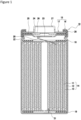
- FIG. 1 is an axial cross-sectional view of a non-aqueous electrolyte secondary battery 10 according to an example embodiment.
- the non-aqueous electrolyte secondary battery 10 illustrated in FIG. 1 includes an electrode assembly 14 and a non-aqueous electrolyte (not shown) received in a battery case 15.
- the electrode assembly 14 has a wound configuration in which a positive electrode 11 and a negative electrode 12 are wound with a separator 13 therebetween.
- the electrode assembly 14 may have a configuration other than the wound configuration, such as a laminate electrode assembly 14 including the positive electrode 11 and the negative electrode 12 alternately stacked via the separator.
- non-aqueous solvent (organic solvent) of the non-aqueous electrolyte examples include carbonates, lactones, ethers, ketones, esters, and mixtures of two or more of these solvents.
- cyclic carbonates such as ethylene carbonate (EC), propylene carbonate (PC), and butylene carbonate
- chain carbonates such as dimethyl carbonate (DMC), ethyl methyl carbonate, diethyl carbonate, and a mixture solvents of cyclic carbonates and chain carbonates, for example, may be used.
- electrolyte salts of the non-aqueous electrolyte examples include LiPF 6 , LiBF 4 , LiCF 3 SO 3 , and mixtures of these.
- a dissolved amount of the electrolyte salt with respect to the non-aqueous solvent may be 0.5 to 2.0 mol/L, for example.
- a direction toward a sealing assembly 17 of the battery case 15 indicates upward, and a direction toward the bottom of an exterior package 16 indicates downward.
- the battery case 15 includes the exterior package 16 and a sealing assembly 17 that closes an opening of the exterior package 16.
- Insulating plates 18 and 19 are disposed on top and bottom of the electrode assembly 14, respectively.
- a positive electrode lead 20 extends through a through hole in the insulating plate 18 toward the sealing assembly 17 and is welded on an underside of a filter 23 that is a bottom plate of the sealing assembly 17.
- a cap 27 that is a top plate of the sealing assembly 17 electrically connected to the filter 23 serves as a positive electrode terminal.
- a negative electrode lead 21 extends through a through hole in the insulating plate 19 towards a bottom of the exterior package 16 and is welded to an inner face of the bottom of the exterior package 16.
- the exterior package 16 serves as a negative electrode terminal.
- the negative electrode lead 21 passes external to the insulating plate 19 to extend toward the bottom of the exterior package 16 and is welded on the inner face of the exterior package 16.
- the battery case 15 may be a metal external case having a shape of a cylinder, a rectangle, a coin, a button, or the like, or a pouch exterior package made of resin sheets and metal sheets that are laminated, for example.
- the exterior package 16 is a cylindrical metal exterior can with a bottom.
- a gasket 28 is disposed between the exterior package 16 and the sealing assembly 17 to secure airtightness within the battery case 15.
- the exterior package 16 includes a projecting portion 22 formed, for example, by pressing the side face thereof inward to support the sealing assembly 17.
- the projecting portion 22 is preferably formed annularly along the circumferential direction of the exterior package 16 to support the sealing assembly 17 on its upper face.
- the sealing assembly 17 include the filter 23, a lower valve element 24, an insulating member 25, an upper valve element 26, and the cap 27 that are stacked in sequence from a direction where the electrode assembly 14 is located.
- the components of the sealing assembly 17 have, for example, either a disc shape or a ring shape and are, except for the insulating member 25, electrically connected to each other.
- the lower valve element 24 and the upper valve element 26 are connected to each other at their center portions, and the insulating member 25 is interposed between their peripheral portions.
- the lower valve element 24 breaks to deform and push the upper valve element 26 toward the cap 27, resulting in an interruption of the current path between the lower valve element 24 and the upper valve element 26.
- the upper valve element 26 breaks, letting gas escape through an opening of the cap 27.
- the positive electrode 11, the negative electrode 12, and the separator 13 of the electrode assembly 14, particularly a negative electrode mixture layer 42 of the negative electrode 12 will be described in detail below.
- FIG. 2 is a cross sectional view of the negative electrode 12 according to an example embodiment.
- the negative electrode 12 includes a negative electrode collector 40 and a negative electrode mixture layer 42 disposed on a surface of the negative electrode collector 40.
- the negative electrode collector 40 may be a foil of metal, such as copper, that is stable within a potential range of the negative electrode 12 or a film including such metal on its surface layer.
- the negative electrode mixture layer 42 includes two half regions 42a and 42b formed by equally dividing the width of the negative electrode mixture layer 42 into halves at the center Z. The half region 42a is closer to the negative electrode collector 40 and the half region 42b is farther from the negative electrode collector 40 and closer to an outer surface of the negative electrode mixture layer 42.
- the negative electrode mixture layer 42 contains graphite particles 30 as negative electrode active materials and a rubber binder as a binder.
- the rubber binder has a repeating molecular structure of double bonds and single bonds, and may be styrene-butadiene rubber (SBR), nitrile butadiene rubber (NBR), and modified forms thereof, for example.
- SBR styrene-butadiene rubber
- NBR nitrile butadiene rubber
- the average primary particle size of the rubber binder is preferably 120 to 250 nm, and more preferably 150 to 230 nm.
- the negative electrode mixture layer 42 may further include, as a binder, fluorine-containing resins such as polytetrafluoroethylene (PTFE) and polyvinylidene fluoride (PVdF), polyacrylonitrile (PAN), polyimides, acrylic resins, and polyolefins, for example.
- PTFE polytetrafluoroethylene
- PVdF polyvinylidene fluoride
- PAN polyacrylonitrile
- polyimides acrylic resins
- the negative electrode mixture layer 42 may also include carboxymethylcellulose (CMC) or salt thereof, polyacrylic acid (PAA) or salt thereof, and polyvinyl alcohol (PVA), for example.
- CMC carboxymethylcellulose
- PAA polyacrylic acid
- PVA polyvinyl alcohol
- the CMC or salt thereof functions as a thickener that regulates a negative electrode active material slurry within an appropriate viscosity range, and also functions as a binder.
- These binders may be used alone, of two or more of the binders are used in combinations.
- the rubber binder is contained in the halt region 42a adjacent to the negative electrode collector in an amount of 90% to 100% of the total amount of the rubber binder contained in the negative electrode mixture layer 42.
- a large amount of rubber binder contained in the half region 42a adjacent to the negative electrode collector enhances adhesion between the negative electrode collector 40 and the negative electrode mixture layer 42.
- a small amount of rubber binder contained in the half region 42b adjacent to the outer surface accelerates absorption of the electrolyte by the negative electrode mixture layer 42. This configuration enables inhibition of deterioration of the rapid charge and discharge cycle characteristics.
- the content of the rubber binder is obtained according to the following procedure.
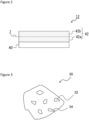
- FIG. 3 is a cross sectional view of a graphite particle 30 contained in the negative electrode mixture layer 42.
- the graphite particle 30 includes, in a cross sectional view of the graphite particle 30, closed voids 32 that are not connected to the surface of the particle through the interior of the particle (hereinafter referred to as "internal voids 32") and voids 34 connected to the surface of the particle through the interior of the particle (hereinafter referred to as "external voids 34").
- the graphite particles 30 include a graphite particle A having an internal porosity or an internal void ratio of 5% or less and a graphite particle B having an internal porosity of 8% to 20%. While the internal porosity of the graphite particle A may be any value that is 5% or less in terms of inhibition of deterioration of the rapid charge and discharge cycle characteristics, it is preferably 1% to 5%, and is more preferably 3% to 5%. While the internal porosity of the graphite particle B may also be any value that is 8% to 20% in terms of inhibition of deterioration of the rapid charge and discharge cycle characteristics, it is preferably 10% to 18%, and is more preferably 12% to 16%.
- the internal porosity of the graphite particle 30 is a two-dimensional value obtained from a ratio of the area of the internal voids 32 in the graphite particle 30 with respect to the cross sectional area of the graphite particle 30.
- the internal porosity of the graphite particle 30 is determined according to the following procedure.
- the graphite particles A and B are produced, for example, as follows:
- coke (a precursor) serving as a primary material is pulverized into particles having a predetermined size, and, after aggregating the pulverized coke particles using an aggregating agent, the coke aggregate is baked at temperatures of 2600°C or higher for graphitization and is then screened to form graphite particles A having a desired size.
- the internal porosity is adjustable to 5% or less by regulating the particle size of the pulverized precursors or the particle size of the aggregated precursors, for example.
- the average particle size (median diameter D50) of the pulverized precursor is within a range of 12 ⁇ m to 25 ⁇ m, for example. To reduce the internal porosity within the range of 5% or less, it is preferable to increase the particle size of the pulverized precursors.
- coke (a precursor) serving as a primary material is pulverized into a predetermined size, and, after aggregating the pulverized coke particles using an aggregating agent, an aggregate of coke is further pressed into a block shape and baked at temperatures of 2600°C or higher for graphitization.
- the graphitized block of molded article is pulverized and screened, thereby forming graphite particles B having a desired size.
- the internal porosity is adjustable to 8% to 20% by regulating an amount of volatile components to be added to the block-shape molded article.
- An aggregating agent to be added to the coke (precursor), which partially volatilizes during baking, may be used as volatile components. Examples of such an aggregating agent include pitch.
- the inter-planar spacing (d 002 ) of (002) planes of the graphite particles A and B used in the present embodiment according to X-ray wide angle diffraction is preferably 0.3354 nm or more, for example, and more preferably 0.3357 nm or more, and also is preferably less than 0.340 nm, and more preferably 0.338 nm or less.
- the crystallite size (Lc (002)) of the graphite particles A and B used in the present embodiment which is determined according to the X-ray diffraction, is preferably 5 nm or more, for example, and more preferably 10 nm or more, and also is preferably 300 nm or less and more preferably 200 nm or less.
- the inter-planar spacing (d 002 ) and the crystallite size (Lc(002)) that satisfy the above range tend to increase the battery capacity of the non-aqueous electrolyte secondary battery 10 as compared to those that do not fall within the above range.
- the negative electrode mixture layer 42 illustrated in FIG. 2 includes two equally divided half regions in its thickness direction, and the graphite particles A are contained in the half region 42b of the negative electrode mixture layer 42 adjacent to the outer surface in a greater amount than in the half region 42a of the negative electrode mixture layer 42 adjacent to the negative electrode collector.
- Inclusion of a large amount of graphite particles A having a lower internal porosity in the half region 42b adjacent to the outer surface results in an increase in voids between active material particles that serve as absorbing paths of electrolyte in the half region 42b adjacent to the outer surface, as compared when the graphite particles A are uniformly distributed in the negative electrode mixture layer 42. This allows rapid absorption of the electrolyte into the negative electrode mixture layer 42.
- the ratio of the graphite particles A and the graphite particles B in the half region 42b adjacent to the outer surface, by a mass ratio is preferably 60:40 to 100:0, and 100:0 is more preferable.
- the ratio of the graphite particles A and the graphite particles B in the half region 42a adjacent to the negative electrode collector, by a mass ratio is 40:60 to 0:100, and 0:100 is more preferable.
- a method for producing the negative electrode mixture layer 42 including the graphite particles A in a greater amount in the half region 42b adjacent to the outer surface than in the half region 42a adjacent to the negative electrode collector will be described.
- a negative electrode active material containing the graphite particles B (and graphite particles A as required), a binder, and a solvent such as water are mixed to first formulate a negative electrode mixture slurry for a region adjacent to the negative electrode collector.
- a negative electrode active material containing the graphite particles A in a greater amount than the amount in the negative electrode mixture slurry for a region adjacent to the negative electrode collector (and the graphite particles B as required), a binder, and a solvent such as water, are mixed to separately formulate a negative electrode mixture slurry for a region adjacent to the outer surface. Then, after the negative electrode mixture slurry for a region adjacent to the negative electrode collector is applied to each of opposite surfaces of the negative electrode collector 40, the negative electrode mixture slurry for a region adjacent to the outer surface is applied to the coating of the negative electrode mixture slurry for a region adjacent to the negative electrode collector on each surface and then the whole coating is dried, so that the negative electrode mixture layer 42 can be formed.
- the negative electrode mixture slurry for a region adjacent to the outer surface is applied before the negative electrode mixture slurry for a region adjacent to the negative electrode collector has been dried
- the negative electrode mixture slurry for a region adjacent to the outer surface may be applied after the negative electrode mixture slurry for a region adjacent to the negative electrode collector is dried.
- the negative electrode mixture slurry for a region adjacent to the negative electrode collector and the negative electrode mixture slurry for a region adjacent to the outer surface are preferably applied to have an equal thickness, they may have different coating thicknesses.
- the negative electrode mixture slurry for a region adjacent to the negative electrode collector may be partially contained in the half region 42b adjacent to the outer surface, or the negative electrode mixture slurry for a region adjacent to the outer surface may be partially contained in the half region 42a adjacent to the negative electrode collector.
- the negative electrode active material may contain materials that may reversibly occlude and release lithium ions, such as Si-based materials, other than the graphite particles A and B used in the present embodiment.
- Si-based materials include, for example, Si, an alloy containing Si, silicon oxide such as SiO x (where x is 0.8 to 1.6). While the Si-based material is a negative electrode material that enables further increase in the battery capacity as compared to the graphite particle 30, the Si-based materials are disadvantageous in terms of the rapid charge and discharge cycle characteristics due to their large cubical expansion associated with charge and discharge.
- the content of the Si-based material is, for example, preferably 1 mass% to 10 mass%, and more preferably 3 mass% to 7 mass%, with respect to the mass of the negative electrode active material.
- Examples of other materials that can reversibly occlude and release lithium ions include metals that alloy with lithium, such as tin (Sn), or an alloy including a metal element such as Sn and oxides, for example.
- the negative electrode active material may include the example materials described above in an amount of preferably 10 mass% or less with respect to the mass of the negative electrode active material, for example.
- the positive electrode 11 includes a positive electrode collector such as a metal foil and a positive electrode mixture layer disposed on the positive electrode collector.
- a positive electrode collector such as a metal foil and a positive electrode mixture layer disposed on the positive electrode collector.
- the positive electrode collector include a foil of metal that is stable in a potential range of the positive electrode 11, such as aluminum, and a film having such metal disposed on its surface layer.
- the positive electrode mixture layer contains, for example, a positive electrode active material, a binder, and a conductive material.
- the positive electrode 11 can be prepared by, for example, applying a positive electrode mixture slurry containing a positive electrode active material, a binder, and a conductive material, to the positive electrode collector and drying the coating to form a positive electrode mixture layer, and then rolling the positive electrode mixture layer.
- the positive electrode active material examples include lithium transition metal composite oxide containing a transition metal element such as Co, Mn, and Ni, for example.
- the lithium transition metal composite oxide is, for example, Li x CoO 2 , Li x NiO 2 , Li x MnO 2 , Li x Co y Ni 1-y O 2 , Li x Co y M 1-y O 2 , Li x Ni 1-y M y O 2 , Li x Mn 2 O 4 , Li x Mn 2-y M y O 4 , LiMPO 4 , or Li 2 MPO 4 F
- M is at least one of Na, Mg, Sc, Y, Mn, Fe, Co, Ni, Cu, Zn, Al, Cr, Pb, Sb, or B, 0 ⁇ x ⁇ 1.2, 0 ⁇ y ⁇ 0.9, 2.0 ⁇ z ⁇ 2.3), which may be used alone or in combinations.
- the positive electrode active material preferably contains lithium-nickel composite oxide such as Li x NiO 2 , Li x Co y Ni 1-y O 2 , Li x Ni 1-y M y O z (M is at least one of Na, Mg, Sc, Y, Mn, Fe, Co, Ni, Cu, Zn, Al, Cr, Pb, Sb, or B, 0 ⁇ x ⁇ 1.2, 0 ⁇ y ⁇ 0.9, 2.0 ⁇ z ⁇ 2.3), for example.
- lithium-nickel composite oxide such as Li x NiO 2 , Li x Co y Ni 1-y O 2 , Li x Ni 1-y M y O z (M is at least one of Na, Mg, Sc, Y, Mn, Fe, Co, Ni, Cu, Zn, Al, Cr, Pb, Sb, or B, 0 ⁇ x ⁇ 1.2, 0 ⁇ y ⁇ 0.9, 2.0 ⁇ z ⁇ 2.3), for example.
- Examples of the conductive material include carbon particles such as carbon black (CB), acetylene black (AB), Ketjenblack, and graphite, which may be used alone or in combinations.
- carbon black CB
- AB acetylene black
- Ketjenblack Ketjenblack
- graphite graphite
- binder examples include, for example, fluorine-containing resins such as polytetrafluoroethylene (PTFE) and polyvinylidene fluoride (PVdF), polyacrylonitrile (PAN), polyimide resins, acrylic resins, polyolefins, which may be used alone or in combinations.
- fluorine-containing resins such as polytetrafluoroethylene (PTFE) and polyvinylidene fluoride (PVdF), polyacrylonitrile (PAN), polyimide resins, acrylic resins, polyolefins, which may be used alone or in combinations.
- the separator 13 is an ion-permeable and insulating porous sheet, for example.
- the porous sheet include a microporous thin film, woven fabric, and nonwoven fabric.
- Suitable examples of materials for the separator 13 include olefin resins such as polyethylene and polypropylenes, and cellulose.
- the separator 13 may have either a single-layer structure or a multilayer structure.
- the separator 13 may have a laminate structure including a cellulose fiber layer and a thermoplastic resin fiber layer such as olefin resins.
- the separator 13 may also be a multi-layer separator 13 including a polyethylene layer and a polypropylene layer, or may include a surface coated with a material such as an aramid resin and ceramic, for example.
- an aluminum-containing lithium nickel cobalt oxide (LiNi 0.88 Co 0.09 Al 0.03 O 2 ) was used. Specifically, 100 parts by mass of a positive electrode active material, 1 part of mass of acetylene black (AB) as a conductive material, and 0.9 parts by mass of polyvinylidene fluoride (PVdF) were mixed, and a proper amount of N-methyl-2-pyrrolidone (NMP) was further added to the mixture to prepare a positive electrode mixture slurry. Subsequently, the positive electrode mixture slurry was applied onto each of opposite surfaces of the positive electrode collector formed of an aluminum foil (having a thickness of 15 ⁇ m) by doctor blading, for example. After drying the coating, the coating is rolled by a pressure roll to form a positive electrode having a positive electrode mixture layer on each of the opposite surfaces of the positive electrode collector.
- NMP N-methyl-2-pyrrolidone
- Coke was pulverized into particles having an average particle size (median diameter D50) of 12 ⁇ m.
- Pitch was added to the pulverized coke as a binder to allow the coke to aggregate into particles having an average particle size (median diameter D50) of 17 ⁇ m.
- the aggregates were baked at 2800°C for graphitization, the aggregates were screened with a 250 mesh screen, and thus graphite particles A having an average particle size (median diameter D50) of 23 ⁇ m were formed.
- Coke was pulverized into particles having an average particle size (median diameter D50) of 15 ⁇ m.
- isotropic pressure was further applied to the aggregates to prepare block-shape molded articles having a density of 1.6g/cm 3 to 1.9g/cm 3 .
- the block molded articles were baked at 2800°C for graphitization, the block molded articles were screened with a 250 mesh screen, and thus graphite particles B having an average particle size (median diameter D50) of 23 ⁇ m were formed.
- a negative electrode active material A to be contained in a half region of the negative electrode mixture layer close of the outer surface was prepared by mixing 100 parts by mass of the graphite particles A and 5 parts by mass of SiO.
- the negative electrode active material A, carboxymethylcellulose (CMC), and polyacrylic acid (PAA) were mixed in a mass ratio of 100:1:1 to formulate a negative electrode mixture slurry for a region adjacent to the outer surface.
- 100 parts by mass of the graphite particles B and 5 parts by mass of SiO were mixed to form a negative electrode active material B to be contained in a half region of the negative electrode mixture layer adjacent to the negative electrode collector.
- This negative electrode active material B carboxymethylcellulose (CMC), polyacrylic acid (PAA), and styrene-butadiene rubber (SBR) were mixed in a mass ratio of 100:1:1:1 to formulate a negative electrode mixture slurry for a region adjacent to the negative electrode collector.
- the average primary particle size of SBR was 150 nm.
- the negative electrode mixture slurry for a region adjacent to the negative electrode collector was applied to each of opposite surfaces of the negative electrode collector formed of a copper foil by doctor blading, for example. After drying the coating, the negative electrode mixture slurry for a region adjacent to the outer surface was applied to the coating and dried, and then the coating was rolled by a pressure roll to form a negative electrode having a negative electrode mixture layer on each of the opposite surfaces of the negative electrode collector.
- the mass ratio of the graphite particles A and the graphite particles B is 100:0 in the half region of the negative electrode mixture layer adjacent to the outer surface
- the mass ratio of the graphite particles A and the graphite particles B is 0:100 in the half region of the negative electrode mixture layer adjacent to the outer surface.
- the internal porosities of the graphite particles A and B in the prepared negative electrode were 3% and 15%, respectively.
- the mixing ratio of the rubber binder (rubber binder in the negative electrode mixture slurry for a region adjacent to the outer surface: rubber binder in the negative electrode mixture slurry for a region adjacent to negative electrode collector) was 0:100 in a mass ratio.
- the negative electrode mixture slurry for a region adjacent to the negative electrode collector and the negative electrode mixture slurry for a region adjacent to the outer surface were applied to have an equal coating thickness.
- the ratio of the rubber binder present after drying was 7:93.
- a negative electrode was prepared in a similar manner to EXAMPLE 1 except that 60 parts by mass of the graphite particles A, 40 parts by mass of the graphite particles B, and 5 parts by mass of SiO were mixed to form the negative electrode active material A, and 40 parts by mass of the graphite particles A, 60 parts by mass of the graphite particles B, and 5 parts by mass of SiO were mixed to form the negative electrode active material B.
- the mass ratio of graphite particles A:graphite particles B in the half region of the negative electrode mixture layer adjacent to the outer surface is 60:40
- the mass ratio of graphite particles A:graphite particles B in the half region of the negative electrode mixture layer adjacent to the negative electrode collector is 40:60.
- the ratio of the rubber binder after drying was 9:91.
- a negative electrode active material C 50 parts by mass of the graphite particles A, 50 parts by mass of the graphite particles B, and 5 parts by mass of SiO were mixed to form a negative electrode active material C to be contained in the entire region of the negative electrode mixture layer.
- This negative electrode active material C carboxymethylcellulose (CMC), polyacrylic acid (PAA), and styrene-butadiene rubber (SBR) were mixed in a mass ratio of 100:1:1:1 to formulate a negative electrode mixture slurry.
- This negative electrode mixture slurry was applied to each of opposite surfaces of the negative electrode collector formed of a copper foil by doctor blading.
- the coating was rolled by a pressure roll to form a negative electrode having a negative electrode active material layer on each of the opposite surfaces of the negative electrode collector.
- the mass ratio of the graphite particles A and the graphite particles B is 50:50 in the half region of the negative electrode active material layer adjacent to the outer surface, and the mass ratio of the graphite particles A and the graphite particles B is also 50:50 in the half region of the negative electrode active material layer adjacent to the outer surface.
- the ratio of the rubber binder after drying (rubber binder in the half region of the negative electrode mixture layer adjacent to the outer surface: rubber binder in the half region of the negative electrode mixture layer adjacent to the negative electrode collector), in a mass ratio, was 48:52.
- the negative electrode active material A that is the same as that used in EXAMPLE 1, carboxylmethylcellulose (CMC), polyacrylic acid (PAA), and styrene-butadiene rubber (SBR) were mixed in a mass ratio 100:1:1:0.5 to prepare a negative electrode mixture slurry for a portion adjacent to the outer surface.
- the negative electrode active material B that is the same as that used in EXAMPLE 1, carboxylmethylcellulose (CMC), polyacrylic acid (PAA), and styrene-butadiene rubber (SBR) were mixed at a mass ratio of 100:1:1:0.5 to prepare a negative electrode mixture slurry for a portion adjacent to the negative electrode collector.
- a negative electrode was prepared in a manner similar to EXAMPLE 1 using the negative electrode mixture slurry for a portion adjacent to the outer surface and the negative electrode mixture slurry for a portion adjacent to the negative electrode collector.
- the mass ratio of graphite particles A:graphite particles B in the half region of the negative electrode mixture layer adjacent to the outer surface is 100:0
- the mass ratio of graphite particles A:graphite particles B in the half region of the negative electrode mixture layer adjacent to the negative electrode mixture layer is 0:100.
- the ratio of the rubber binder after drying (rubber binder in the half region of the negative electrode mixture layer adjacent to the outer surface: rubber binder in the half region of the negative electrode mixture layer adjacent to the negative electrode collector), in a mass ratio, was 43:57.
- a negative electrode was prepared in a manner similar to EXAMPLE 1 except that the negative electrode active material C that is used in COMPARATIVE EXAMPLE 1 was used in place of the negative electrode active material A and the negative electrode active material B. More specifically, the mass ratio of graphite particles A:graphite particles B in the half region of the negative electrode mixture layer adjacent to the outer surface is 50:50, and the mass ratio of graphite particles A:graphite particles B in the half region of the negative electrode mixture layer adjacent to the negative electrode mixture layer is also 50:50. The ratio of the rubber binder after drying (rubber binder in the half region of the negative electrode mixture layer adjacent to the outer surface: rubber binder in the half region of the negative electrode mixture layer adjacent to the negative electrode collector), in a mass ratio, was 9:91.
- the negative electrode in each of EXAMPLES and COMPARATIVE EXAMPLES was dried for 10 hours in a thermostatic oven heated to 200°C under nitrogen atmosphere and was then cut to a size of 2 cm ⁇ 5 cm, to thereby prepare a sample. Then, 1.5 ⁇ ml of polypropylene carbonate (PC) was vertically dropped down to each sample, and the time taken until the PC is absorbed into the sample was measured by visual inspection. The measurements were performed 6 times for each sample, and the average value was obtained as a liquid absorbing time.
- PC polypropylene carbonate
- Table 1 shows the liquid absorbing time for the non-aqueous electrolyte secondary battery in each of EXAMPLES and COMPARATIVE EXAMPLES.
- Each of the liquid absorbing time shown in Table 1 is a relative time with respect to the liquid absorbing time in EXAMPLE 1 which is 100. Shorter the liquid absorbing time, swifter the change of the electrolyte in the negative electrode mixture layer, which accelerates absorption of the electrolyte discharged from the negative electrode mixture layer during charging into the negative electrode mixture layer, thereby inhibiting deterioration of the rapid charge and discharge cycle characteristics.
- the liquid absorbing times in EXAMPLES 1 and 2 are both shorter than those in COMPARATIVE EXAMPLES 1 to 3. Note that, in COMPARATIVE EXAMPLE 2 and COMPARATIVE EXAMPLE 3 in which either one of the graphite ratio or the mass ratio of the rubber binder was changed from those of COMPARATIVE EXAMPLE 1, the liquid absorbing times are reduced to 80% and 76%, respectively, of that of COMPARATIVE EXAMPLE 1. Meanwhile, in EXAMPLE 1 in which both the graphite ratio and the mass ratio of the rubber binder were changed from those of COMPARATIVE EXAMPLE 1, the liquid absorbing time was reduced to 45% of that of COMPARATIVE EXAMPLE 1.
- a negative electrode mixture layer containing the graphite particles A in a greater amount in the half region adjacent to the outer surface than in the half region adjacent to the negative electrode collector and also containing the rubber binder in the half region adjacent to the negative electrode collector in an amount of 90 mass% or more enables significant increase in the absorbing rate of the electrolyte, thereby inhibiting deterioration of the rapid charge and discharge cycle characteristics.
Landscapes
- Chemical & Material Sciences (AREA)
- Chemical Kinetics & Catalysis (AREA)
- Electrochemistry (AREA)
- General Chemical & Material Sciences (AREA)
- Composite Materials (AREA)
- Inorganic Chemistry (AREA)
- Battery Electrode And Active Subsutance (AREA)
- Secondary Cells (AREA)
Claims (2)
- Sekundärbatterie (10) mit wasserfreiem Elektrolyt, umfassend:eine Negativelektrode (12), die einen Negativelektrodenkollektor (40) und eine Negativelektroden-Gemischschicht (42) umfasst, die auf einer Oberfläche des Negativelektrodenkollektors (40) angeordnet ist, wobeidie Negativelektroden-Gemischschicht (42) Graphitpartikel A und Graphitpartikel B als ein Negativelektroden-Aktivmaterial und ein Gummibindemittel als ein Bindemittel enthält,dadurch gekennzeichnet, dass die Graphitpartikel A eine innere Porosität von 5 % oder niedriger aufweisen und die Graphitpartikel B eine innere Porosität von 8 % bis 20 % aufweisen, wenn die innere Porosität mit dem in der Beschreibung angegebenen Verfahren gemessen wird, dadurch, dassdie Negativelektroden-Gemischschicht (42) zwei gleich geteilte Halbregionen in einer Dickenrichtung der Negativelektroden-Gemischschicht (42) umfasst und die Graphitpartikel A in einer Halbregion der Negativelektroden-Gemischschicht (42) benachbart zu einer äußeren Oberfläche (42b) der Negativelektroden-Gemischschicht (42) in einem höheren Massenanteil enthalten sind als in einer Halbregion der Negativelektroden-Gemischschicht (42) benachbart zu dem Negativelektrodenkollektor (42a), und dadurch, dassdas Gummibindemittel in der Halbregion benachbart zu dem Negativelektrodenkollektor (42a) in einem Anteil von 90 Massen-% bis 100 Massen-% des gesamten Gummibindemittels enthalten ist, das in der Negativelektroden-Gemischschicht (42) enthalten ist, wenn ein Gummibindemittelgehalt mit dem in der Beschreibung angegebenen Verfahren gemessen wird.
- Sekundärbatterie (10) mit wasserfreiem Elektrolyt nach Anspruch 1, wobei
die Graphitpartikel A und die Graphitpartikel B in der Halbregion benachbart zu der äußeren Oberfläche (42b) in einem Massenverhältnis von 60:40 bis 100:0 enthalten sind.
Applications Claiming Priority (2)
| Application Number | Priority Date | Filing Date | Title |
|---|---|---|---|
| JP2019083098 | 2019-04-24 | ||
| PCT/JP2020/016401 WO2020218083A1 (ja) | 2019-04-24 | 2020-04-14 | 非水電解質二次電池 |
Publications (3)
| Publication Number | Publication Date |
|---|---|
| EP3961757A1 EP3961757A1 (de) | 2022-03-02 |
| EP3961757A4 EP3961757A4 (de) | 2022-05-18 |
| EP3961757B1 true EP3961757B1 (de) | 2025-03-26 |
Family
ID=72942667
Family Applications (1)
| Application Number | Title | Priority Date | Filing Date |
|---|---|---|---|
| EP20794428.1A Active EP3961757B1 (de) | 2019-04-24 | 2020-04-14 | Sekundärbatterie mit wasserfreiem elektrolyt |
Country Status (5)
| Country | Link |
|---|---|
| US (1) | US12191490B2 (de) |
| EP (1) | EP3961757B1 (de) |
| JP (1) | JP7588581B2 (de) |
| CN (1) | CN113728460B (de) |
| WO (1) | WO2020218083A1 (de) |
Families Citing this family (4)
| Publication number | Priority date | Publication date | Assignee | Title |
|---|---|---|---|---|
| EP4586336A3 (de) | 2019-09-27 | 2025-10-08 | Panasonic Intellectual Property Management Co., Ltd. | Negativelektrode für eine lithiumionensekundärbatterie und lithiumionensekundärbatterie |
| CN114430864B (zh) * | 2019-09-27 | 2024-08-23 | 松下知识产权经营株式会社 | 锂离子二次电池用负极和锂离子二次电池 |
| KR20230030409A (ko) * | 2021-08-25 | 2023-03-06 | 삼성에스디아이 주식회사 | 리튬 이차 전지용 전극 및 이를 포함하는 리튬 이차 전지 |
| US20250149554A1 (en) | 2021-08-31 | 2025-05-08 | Panasonic Holdings Corporation | Negative electrode for secondary battery, and secondary battery |
Family Cites Families (20)
| Publication number | Priority date | Publication date | Assignee | Title |
|---|---|---|---|---|
| US5677082A (en) | 1996-05-29 | 1997-10-14 | Ucar Carbon Technology Corporation | Compacted carbon for electrochemical cells |
| JP3945023B2 (ja) | 1998-06-19 | 2007-07-18 | 宇部興産株式会社 | 非水二次電池 |
| US7829222B2 (en) * | 2001-01-25 | 2010-11-09 | Hitachi Chemical Company, Ltd. | Artificial graphite particles and method for manufacturing same, nonaqueous electrolyte secondary cell, negative electrode and method for manufacturing same, and lithium secondary cell |
| US6998192B1 (en) * | 2002-08-29 | 2006-02-14 | Quallion Llc | Negative electrode for a nonaqueous battery |
| JP5810479B2 (ja) * | 2009-05-26 | 2015-11-11 | 日産自動車株式会社 | リチウムイオン二次電池用の電極構造、リチウムイオン二次電池およびリチウムイオン二次電池用の電極の製造方法 |
| JP2012216537A (ja) * | 2011-03-30 | 2012-11-08 | Mitsubishi Chemicals Corp | 非水系二次電池用炭素材、及び負極、並びに、非水系二次電池 |
| JP2014067638A (ja) | 2012-09-26 | 2014-04-17 | Mitsubishi Chemicals Corp | 非水系二次電池用炭素材、及び負極並びに、非水系二次電池 |
| KR20140147475A (ko) * | 2013-06-20 | 2014-12-30 | 에스케이이노베이션 주식회사 | 그라파이트 펠트를 포함하는 소듐 이차전지 |
| US10243205B2 (en) * | 2013-12-27 | 2019-03-26 | Sanyo Electric Co., Ltd. | Negative electrode for non-aqueous electrolyte secondary batteries |
| US10270086B2 (en) * | 2014-01-31 | 2019-04-23 | Sanyo Electric Co., Ltd. | Nonaqueous-electrolyte secondary-battery negative electrode |
| US10749179B2 (en) * | 2014-03-31 | 2020-08-18 | Envision Aesc Energy Devices Ltd. | Graphite-based negative electrode active material, negative electrode, and lithium ion secondary battery |
| JP6697377B2 (ja) * | 2014-03-31 | 2020-05-20 | 株式会社エンビジョンAescエナジーデバイス | リチウムイオン二次電池 |
| CN106663808B (zh) * | 2014-07-07 | 2019-09-06 | 三菱化学株式会社 | 碳材料、碳材料的制造方法、以及使用了碳材料的非水系二次电池 |
| KR101685832B1 (ko) * | 2014-07-29 | 2016-12-12 | 주식회사 엘지화학 | 흑연 2차 입자 및 이를 포함하는 리튬 이차전지 |
| WO2017111542A1 (ko) * | 2015-12-23 | 2017-06-29 | 주식회사 엘지화학 | 리튬 이차전지용 음극활물질 및 이를 포함하는 리튬 이차전지용 음극 |
| KR102088491B1 (ko) * | 2015-12-23 | 2020-03-13 | 주식회사 엘지화학 | 리튬 이차전지용 음극활물질 및 이를 포함하는 리튬 이차전지용 음극 |
| JP6759936B2 (ja) * | 2016-09-28 | 2020-09-23 | 日産自動車株式会社 | 非水電解質二次電池、および負極ユニット |
| CN112292773B (zh) * | 2018-06-15 | 2024-07-30 | 松下新能源株式会社 | 非水电解质二次电池 |
| JP7621243B2 (ja) * | 2019-02-28 | 2025-01-24 | パナソニックエナジー株式会社 | 非水電解質二次電池 |
| EP4586336A3 (de) * | 2019-09-27 | 2025-10-08 | Panasonic Intellectual Property Management Co., Ltd. | Negativelektrode für eine lithiumionensekundärbatterie und lithiumionensekundärbatterie |
-
2020
- 2020-04-14 EP EP20794428.1A patent/EP3961757B1/de active Active
- 2020-04-14 WO PCT/JP2020/016401 patent/WO2020218083A1/ja not_active Ceased
- 2020-04-14 US US17/604,334 patent/US12191490B2/en active Active
- 2020-04-14 CN CN202080030094.0A patent/CN113728460B/zh active Active
- 2020-04-14 JP JP2021516019A patent/JP7588581B2/ja active Active
Also Published As
| Publication number | Publication date |
|---|---|
| US20220216475A1 (en) | 2022-07-07 |
| EP3961757A1 (de) | 2022-03-02 |
| JP7588581B2 (ja) | 2024-11-22 |
| US12191490B2 (en) | 2025-01-07 |
| CN113728460A (zh) | 2021-11-30 |
| CN113728460B (zh) | 2024-09-24 |
| EP3961757A4 (de) | 2022-05-18 |
| JPWO2020218083A1 (de) | 2020-10-29 |
| WO2020218083A1 (ja) | 2020-10-29 |
Similar Documents
| Publication | Publication Date | Title |
|---|---|---|
| EP4037015B1 (de) | Negativelektrode für lithium-ionen-sekundärbatterie sowie lithium-ionen-sekundärbatterie | |
| EP3961757B1 (de) | Sekundärbatterie mit wasserfreiem elektrolyt | |
| JP7674268B2 (ja) | 非水電解質二次電池用負極、及び非水電解質二次電池 | |
| JPWO2019239947A1 (ja) | 非水電解質二次電池 | |
| WO2023171564A1 (ja) | 非水電解液二次電池 | |
| JPWO2019239948A1 (ja) | 非水電解質二次電池 | |
| WO2021117480A1 (ja) | 非水電解液二次電池 | |
| JP7682099B2 (ja) | 非水電解質二次電池 | |
| EP3683865B1 (de) | Elektrode und batterie mit wasserfreiem elektrolyt | |
| EP4145563A1 (de) | Positivelektrodenaktivmaterial für sekundärbatterien mit wasserfreiem elektrolyt und sekundärbatterie mit wasserfreiem elektrolyt | |
| WO2021117748A1 (ja) | 非水電解質二次電池 | |
| JP7783200B2 (ja) | 非水電解質二次電池 | |
| WO2024070220A1 (ja) | 非水電解質二次電池 | |
| EP4030508B1 (de) | Positivelektroden-aktivmaterial für eine sekundärbatterie mit nichtwässrigem elektrolyten und sekundärbatterie mit nichtwässrigem elektrolyten | |
| EP4084204A1 (de) | Separator für eine sekundärbatterie mit wasserfreiem elektrolyt und sekundärbatterie mit wasserfreiem elektrolyt | |
| JP7738484B2 (ja) | 非水電解質二次電池 | |
| EP4550442A1 (de) | Sekundärbatterie mit nichtwässrigem elektrolyten | |
| EP4365972A1 (de) | Positivelektrode für sekundärbatterien mit wasserfreiem elektrolyt und sekundärbatterie mit wasserfreiem elektrolyt | |
| EP4621900A1 (de) | Sekundärbatterie mit nichtwässrigem elektrolyten | |
| JP7646562B2 (ja) | 非水電解質二次電池用負極、非水電解質二次電池、及び非水電解質二次電池用負極の製造方法 | |
| TW202437575A (zh) | 非水電解質二次電池 | |
| WO2025062937A1 (ja) | 二次電池 | |
| WO2025205755A1 (ja) | 非水電解質二次電池用負極、非水電解質二次電池、および電池パック | |
| WO2024161977A1 (ja) | 非水電解質二次電池 | |
| WO2022158381A1 (ja) | 負極活物質用複合体粒子、負極活物質用複合体粒子の製造方法、及び非水電解質二次電池 |
Legal Events
| Date | Code | Title | Description |
|---|---|---|---|
| STAA | Information on the status of an ep patent application or granted ep patent |
Free format text: STATUS: THE INTERNATIONAL PUBLICATION HAS BEEN MADE |
|
| PUAI | Public reference made under article 153(3) epc to a published international application that has entered the european phase |
Free format text: ORIGINAL CODE: 0009012 |
|
| STAA | Information on the status of an ep patent application or granted ep patent |
Free format text: STATUS: REQUEST FOR EXAMINATION WAS MADE |
|
| 17P | Request for examination filed |
Effective date: 20210916 |
|
| AK | Designated contracting states |
Kind code of ref document: A1 Designated state(s): AL AT BE BG CH CY CZ DE DK EE ES FI FR GB GR HR HU IE IS IT LI LT LU LV MC MK MT NL NO PL PT RO RS SE SI SK SM TR |
|
| A4 | Supplementary search report drawn up and despatched |
Effective date: 20220422 |
|
| RIC1 | Information provided on ipc code assigned before grant |
Ipc: H01M 4/62 20060101ALI20220414BHEP Ipc: H01M 4/587 20100101ALI20220414BHEP Ipc: H01M 4/36 20060101ALI20220414BHEP Ipc: H01M 4/133 20100101AFI20220414BHEP |
|
| DAV | Request for validation of the european patent (deleted) | ||
| DAX | Request for extension of the european patent (deleted) | ||
| GRAP | Despatch of communication of intention to grant a patent |
Free format text: ORIGINAL CODE: EPIDOSNIGR1 |
|
| STAA | Information on the status of an ep patent application or granted ep patent |
Free format text: STATUS: GRANT OF PATENT IS INTENDED |
|
| INTG | Intention to grant announced |
Effective date: 20241018 |
|
| P01 | Opt-out of the competence of the unified patent court (upc) registered |
Free format text: CASE NUMBER: APP_65744/2024 Effective date: 20241212 |
|
| GRAS | Grant fee paid |
Free format text: ORIGINAL CODE: EPIDOSNIGR3 |
|
| GRAA | (expected) grant |
Free format text: ORIGINAL CODE: 0009210 |
|
| STAA | Information on the status of an ep patent application or granted ep patent |
Free format text: STATUS: THE PATENT HAS BEEN GRANTED |
|
| RAP3 | Party data changed (applicant data changed or rights of an application transferred) |
Owner name: SANYO ELECTRIC CO., LTD. |
|
| RAP1 | Party data changed (applicant data changed or rights of an application transferred) |
Owner name: PANASONIC ENERGY CO., LTD. |
|
| AK | Designated contracting states |
Kind code of ref document: B1 Designated state(s): AL AT BE BG CH CY CZ DE DK EE ES FI FR GB GR HR HU IE IS IT LI LT LU LV MC MK MT NL NO PL PT RO RS SE SI SK SM TR |
|
| REG | Reference to a national code |
Ref country code: GB Ref legal event code: FG4D |
|
| REG | Reference to a national code |
Ref country code: CH Ref legal event code: EP |
|
| REG | Reference to a national code |
Ref country code: DE Ref legal event code: R096 Ref document number: 602020048379 Country of ref document: DE |
|
| REG | Reference to a national code |
Ref country code: IE Ref legal event code: FG4D |
|
| PG25 | Lapsed in a contracting state [announced via postgrant information from national office to epo] |
Ref country code: RS Free format text: LAPSE BECAUSE OF FAILURE TO SUBMIT A TRANSLATION OF THE DESCRIPTION OR TO PAY THE FEE WITHIN THE PRESCRIBED TIME-LIMIT Effective date: 20250626 |
|
| PG25 | Lapsed in a contracting state [announced via postgrant information from national office to epo] |
Ref country code: FI Free format text: LAPSE BECAUSE OF FAILURE TO SUBMIT A TRANSLATION OF THE DESCRIPTION OR TO PAY THE FEE WITHIN THE PRESCRIBED TIME-LIMIT Effective date: 20250326 |
|
| PGFP | Annual fee paid to national office [announced via postgrant information from national office to epo] |
Ref country code: DE Payment date: 20250508 Year of fee payment: 6 |
|
| PGFP | Annual fee paid to national office [announced via postgrant information from national office to epo] |
Ref country code: GB Payment date: 20250515 Year of fee payment: 6 |
|
| REG | Reference to a national code |
Ref country code: LT Ref legal event code: MG9D |
|
| PG25 | Lapsed in a contracting state [announced via postgrant information from national office to epo] |
Ref country code: NO Free format text: LAPSE BECAUSE OF FAILURE TO SUBMIT A TRANSLATION OF THE DESCRIPTION OR TO PAY THE FEE WITHIN THE PRESCRIBED TIME-LIMIT Effective date: 20250626 |
|
| PG25 | Lapsed in a contracting state [announced via postgrant information from national office to epo] |
Ref country code: HR Free format text: LAPSE BECAUSE OF FAILURE TO SUBMIT A TRANSLATION OF THE DESCRIPTION OR TO PAY THE FEE WITHIN THE PRESCRIBED TIME-LIMIT Effective date: 20250326 |
|
| PG25 | Lapsed in a contracting state [announced via postgrant information from national office to epo] |
Ref country code: LV Free format text: LAPSE BECAUSE OF FAILURE TO SUBMIT A TRANSLATION OF THE DESCRIPTION OR TO PAY THE FEE WITHIN THE PRESCRIBED TIME-LIMIT Effective date: 20250326 |
|
| PGFP | Annual fee paid to national office [announced via postgrant information from national office to epo] |
Ref country code: FR Payment date: 20250505 Year of fee payment: 6 |
|
| PG25 | Lapsed in a contracting state [announced via postgrant information from national office to epo] |
Ref country code: GR Free format text: LAPSE BECAUSE OF FAILURE TO SUBMIT A TRANSLATION OF THE DESCRIPTION OR TO PAY THE FEE WITHIN THE PRESCRIBED TIME-LIMIT Effective date: 20250627 Ref country code: BG Free format text: LAPSE BECAUSE OF FAILURE TO SUBMIT A TRANSLATION OF THE DESCRIPTION OR TO PAY THE FEE WITHIN THE PRESCRIBED TIME-LIMIT Effective date: 20250326 |
|
| REG | Reference to a national code |
Ref country code: NL Ref legal event code: MP Effective date: 20250326 |
|
| PG25 | Lapsed in a contracting state [announced via postgrant information from national office to epo] |
Ref country code: NL Free format text: LAPSE BECAUSE OF FAILURE TO SUBMIT A TRANSLATION OF THE DESCRIPTION OR TO PAY THE FEE WITHIN THE PRESCRIBED TIME-LIMIT Effective date: 20250326 |
|
| PG25 | Lapsed in a contracting state [announced via postgrant information from national office to epo] |
Ref country code: SE Free format text: LAPSE BECAUSE OF FAILURE TO SUBMIT A TRANSLATION OF THE DESCRIPTION OR TO PAY THE FEE WITHIN THE PRESCRIBED TIME-LIMIT Effective date: 20250326 |
|
| REG | Reference to a national code |
Ref country code: AT Ref legal event code: MK05 Ref document number: 1779858 Country of ref document: AT Kind code of ref document: T Effective date: 20250326 |
|
| PG25 | Lapsed in a contracting state [announced via postgrant information from national office to epo] |
Ref country code: SM Free format text: LAPSE BECAUSE OF FAILURE TO SUBMIT A TRANSLATION OF THE DESCRIPTION OR TO PAY THE FEE WITHIN THE PRESCRIBED TIME-LIMIT Effective date: 20250326 |
|
| PG25 | Lapsed in a contracting state [announced via postgrant information from national office to epo] |
Ref country code: ES Free format text: LAPSE BECAUSE OF FAILURE TO SUBMIT A TRANSLATION OF THE DESCRIPTION OR TO PAY THE FEE WITHIN THE PRESCRIBED TIME-LIMIT Effective date: 20250326 Ref country code: PT Free format text: LAPSE BECAUSE OF FAILURE TO SUBMIT A TRANSLATION OF THE DESCRIPTION OR TO PAY THE FEE WITHIN THE PRESCRIBED TIME-LIMIT Effective date: 20250728 |
|
| PG25 | Lapsed in a contracting state [announced via postgrant information from national office to epo] |
Ref country code: PL Free format text: LAPSE BECAUSE OF FAILURE TO SUBMIT A TRANSLATION OF THE DESCRIPTION OR TO PAY THE FEE WITHIN THE PRESCRIBED TIME-LIMIT Effective date: 20250326 Ref country code: IT Free format text: LAPSE BECAUSE OF FAILURE TO SUBMIT A TRANSLATION OF THE DESCRIPTION OR TO PAY THE FEE WITHIN THE PRESCRIBED TIME-LIMIT Effective date: 20250326 |
|
| PG25 | Lapsed in a contracting state [announced via postgrant information from national office to epo] |
Ref country code: AT Free format text: LAPSE BECAUSE OF FAILURE TO SUBMIT A TRANSLATION OF THE DESCRIPTION OR TO PAY THE FEE WITHIN THE PRESCRIBED TIME-LIMIT Effective date: 20250326 |
|
| PG25 | Lapsed in a contracting state [announced via postgrant information from national office to epo] |
Ref country code: EE Free format text: LAPSE BECAUSE OF FAILURE TO SUBMIT A TRANSLATION OF THE DESCRIPTION OR TO PAY THE FEE WITHIN THE PRESCRIBED TIME-LIMIT Effective date: 20250326 |
|
| PG25 | Lapsed in a contracting state [announced via postgrant information from national office to epo] |
Ref country code: RO Free format text: LAPSE BECAUSE OF FAILURE TO SUBMIT A TRANSLATION OF THE DESCRIPTION OR TO PAY THE FEE WITHIN THE PRESCRIBED TIME-LIMIT Effective date: 20250326 |
|
| PG25 | Lapsed in a contracting state [announced via postgrant information from national office to epo] |
Ref country code: SK Free format text: LAPSE BECAUSE OF FAILURE TO SUBMIT A TRANSLATION OF THE DESCRIPTION OR TO PAY THE FEE WITHIN THE PRESCRIBED TIME-LIMIT Effective date: 20250326 |
|
| PG25 | Lapsed in a contracting state [announced via postgrant information from national office to epo] |
Ref country code: IS Free format text: LAPSE BECAUSE OF FAILURE TO SUBMIT A TRANSLATION OF THE DESCRIPTION OR TO PAY THE FEE WITHIN THE PRESCRIBED TIME-LIMIT Effective date: 20250726 |
|
| REG | Reference to a national code |
Ref country code: CH Ref legal event code: H13 Free format text: ST27 STATUS EVENT CODE: U-0-0-H10-H13 (AS PROVIDED BY THE NATIONAL OFFICE) Effective date: 20251125 |
|
| PG25 | Lapsed in a contracting state [announced via postgrant information from national office to epo] |
Ref country code: LU Free format text: LAPSE BECAUSE OF NON-PAYMENT OF DUE FEES Effective date: 20250414 |
|
| PG25 | Lapsed in a contracting state [announced via postgrant information from national office to epo] |
Ref country code: MC Free format text: LAPSE BECAUSE OF FAILURE TO SUBMIT A TRANSLATION OF THE DESCRIPTION OR TO PAY THE FEE WITHIN THE PRESCRIBED TIME-LIMIT Effective date: 20250326 |
|
| REG | Reference to a national code |
Ref country code: BE Ref legal event code: MM Effective date: 20250430 |
|
| PG25 | Lapsed in a contracting state [announced via postgrant information from national office to epo] |
Ref country code: DK Free format text: LAPSE BECAUSE OF FAILURE TO SUBMIT A TRANSLATION OF THE DESCRIPTION OR TO PAY THE FEE WITHIN THE PRESCRIBED TIME-LIMIT Effective date: 20250326 |
|
| PG25 | Lapsed in a contracting state [announced via postgrant information from national office to epo] |
Ref country code: BE Free format text: LAPSE BECAUSE OF NON-PAYMENT OF DUE FEES Effective date: 20250430 |
|
| PG25 | Lapsed in a contracting state [announced via postgrant information from national office to epo] |
Ref country code: CH Free format text: LAPSE BECAUSE OF NON-PAYMENT OF DUE FEES Effective date: 20250430 |
|
| PG25 | Lapsed in a contracting state [announced via postgrant information from national office to epo] |
Ref country code: CZ Free format text: LAPSE BECAUSE OF FAILURE TO SUBMIT A TRANSLATION OF THE DESCRIPTION OR TO PAY THE FEE WITHIN THE PRESCRIBED TIME-LIMIT Effective date: 20250326 |
|
| PLBE | No opposition filed within time limit |
Free format text: ORIGINAL CODE: 0009261 |
|
| STAA | Information on the status of an ep patent application or granted ep patent |
Free format text: STATUS: NO OPPOSITION FILED WITHIN TIME LIMIT |
|
| REG | Reference to a national code |
Ref country code: CH Ref legal event code: L10 Free format text: ST27 STATUS EVENT CODE: U-0-0-L10-L00 (AS PROVIDED BY THE NATIONAL OFFICE) Effective date: 20260211 |