EP3961160A1 - Sensorgehäuse - Google Patents
Sensorgehäuse Download PDFInfo
- Publication number
- EP3961160A1 EP3961160A1 EP21000220.0A EP21000220A EP3961160A1 EP 3961160 A1 EP3961160 A1 EP 3961160A1 EP 21000220 A EP21000220 A EP 21000220A EP 3961160 A1 EP3961160 A1 EP 3961160A1
- Authority
- EP
- European Patent Office
- Prior art keywords
- clamping space
- space
- sealing
- sensor
- terminal
- Prior art date
- Legal status (The legal status is an assumption and is not a legal conclusion. Google has not performed a legal analysis and makes no representation as to the accuracy of the status listed.)
- Granted
Links
Images

Classifications
-
- G—PHYSICS
- G01—MEASURING; TESTING
- G01D—MEASURING NOT SPECIALLY ADAPTED FOR A SPECIFIC VARIABLE; ARRANGEMENTS FOR MEASURING TWO OR MORE VARIABLES NOT COVERED IN A SINGLE OTHER SUBCLASS; TARIFF METERING APPARATUS; MEASURING OR TESTING NOT OTHERWISE PROVIDED FOR
- G01D11/00—Component parts of measuring arrangements not specially adapted for a specific variable
- G01D11/24—Housings ; Casings for instruments
- G01D11/245—Housings for sensors
Definitions
- the invention relates to a sensor housing comprising a head part with a sensor space for accommodating a sensor and a connection part with a terminal space for accommodating a terminal block.
- a typical design of sensors such as inductive or capacitive proximity sensors, includes a two-part housing.
- the sensor is arranged in a head part and a contacting device, e.g. a terminal block, for connecting a cable coming from the outside is arranged in a connection part.
- a contacting device e.g. a terminal block
- the connection part or the space enclosed by the connection part is therefore often also referred to as a terminal space.
- the sensor in the head part is connected to the contacting device by electrical connections, for which purpose the head part and the connection part have corresponding through-openings and optionally further contacting devices, such as contact pins.
- the connecting part typically consists of a base and a cover. It is known to assemble the lower part and the cover along joining surfaces running perpendicularly to a joining direction. It is also known to arrange a circumferential seal, for example a rubber ring or a circumferential flat seal, on one of the joining surfaces for sealing purposes.
- a circumferential seal for example a rubber ring or a circumferential flat seal
- the connection between the lid and the base is fixed with a total of three screws.
- the object of the invention is to specify a device that develops the prior art.
- a sensor housing is to be provided with a mechanism for connecting and sealing between the cover and lower part of the connection part that is as reliable and user-independent as possible and can be operated without tools.
- a sensor housing comprising a head part with a sensor space for accommodating a sensor and a connection part adjoining the head part with a clamping space for accommodating a terminal block, the head part having a through-opening in a rear wall adjoining the connection part for the passage of electrical connections, for example: cable and/or plug bushing in the sensor space.
- connection part comprises a terminal space base and a terminal space cover, the terminal space base and the terminal space cover being assembled in a closing direction, so that the terminal space base and the terminal space cover adjoin one another and enclose the terminal space, the terminal space cover being connected to the head part by means of a connecting means.
- the terminal space cover has a side wall adjoining the rear wall of the head part with a through opening that at least overlaps the through opening of the head part for carrying out electrical connections, e.g. cable and/or plug bushing from the sensor space into the terminal space.
- the terminal space bottom part has a side wall with an entry opening for cable and/or connector bushing.
- the terminal space cover and the terminal space base each have a sealing surface, the sealing surfaces facing each other and running parallel or at an angle of at most 3° or at most 1.5° to one another.
- the sealing surfaces also each extend along a closed curve around a central axis of the connecting part running parallel to the closing direction and at an angle of at least 0° and at most 45° or at most 30° or at most 20° to the longitudinal axis, so that a distance between each Sealing surface and the longitudinal axis is constant or decreases in the closing direction.
- a circumferential sealing element for sealing the clamping space is arranged between the sealing surface of the clamping space cover and the sealing surface of the clamping space base.
- terminal space base and terminal space cover do not specify an orientation of the connection part or a position/alignment of the two parts of the connection part.
- the terms are only used to differentiate or to identify the two parts of the two-part connection part.
- clamping space cover and the clamping space base each have edges and/or surfaces along which they can be assembled or joined together.
- the terminal block to be accommodated is designed, for example, as a separate component and can be arranged in the terminal space.
- the terminal connection block is designed in one piece with the lower part of the terminal space, for example.
- the joint surfaces of the terminal space cover lie on the joint surfaces of the terminal space base, so that the terminal space cover and the terminal space base enclose the terminal space except for the openings for electrical connections, such as cable and/or plug bushings.
- sealing surface refers to surfaces which, after assembly, do not abut one another like joint surfaces, but are spaced apart from one another by a sealing element.
- closing direction ie the direction in which the clamping space cover is placed on the clamping space base or vice versa, and the alignment of the joining and sealing surfaces are mutually dependent. In particular, undercuts should be avoided with regard to the closing direction.
- connection part consists of a cuboid body with an essentially cylindrical cavity as a clamping space, e.g. with an oval base area, with the clamping space base covering the lower half of the body and the clamping space cover covering the upper half of the body.
- clamping space cover and the clamping space base each comprise a part of the clamping space as a depression.
- the separating or cut surfaces that is to say the edge surfaces of the side walls surrounding the cylindrical recess which adjoin one another, form the joining surfaces.
- the sealing surfaces form one upper edge section of the inner surface of the depression in the clamping space bottom part on the one hand and an outer surface of a connecting part of the clamping space cover protruding into the depression of the clamping space bottom part, the connecting section protruding as a thin wall section extending the depression beyond the further side surfaces of the clamping space lid.
- a connecting part is just as easily arranged on the clamping space lower part and protrudes into the recess of the clamping space cover for sealing.
- the sealing element acts in particular radially with respect to the central axis as a result of sealing surfaces which run parallel or at least at an acute angle. As a result, the sealing effect is less dependent on a force acting in the closing direction, i.e. parallel to the central axis, to close the connecting part, e.g. by screwing the two components together.
- the effect of the sealing element is thus independent of a tightening torque of a screw connection and thus also independent of handling or the user.
- the contact pressure force acting on the sealing element depends on the dimensions of the housing, in particular the sealing surfaces, and can therefore be reproduced well.
- the sealing surface of the clamping space cover or the sealing surface of the clamping space base has a groove for receiving of the sealing element.
- each sealing surface is designed as the lateral surface of a cylinder or a truncated cone.
- any cylindrical shape or frustoconical shape is encompassed.
- it can be a straight or oblique cylinder or truncated cone and the base can have any shape.
- the base of the cylinder or truncated cone is rounded, preferably oval.
- the base is perpendicular or oriented at an angle to the central axis.
- a rounded, continuous inner or outer circumference of the sealing surfaces makes it possible to achieve good sealing with a radial sealing element that follows the circumference.
- a contact pressure force that is as uniform as possible acts on the sealing element, with the contact pressure force essentially depending on the dimensions or the shape of the housing parts.
- the sealing surfaces each enclose a surface in a projection along the central axis, the surface being circular or oval in shape.
- one of the sealing surfaces is designed as an extension of an inner surface of the clamping space.
- the inner surface of the terminal space or an upper edge section of the inner surface of a recess in the lower part of the terminal space or the upper part of the terminal space serves as a sealing surface, with the recess forming part of the terminal space.
- the sensor housing corresponds to the IP 68 standard or the IP 69K standard.
- the inductive or capacitive proximity sensor has a sensor housing according to one of the preceding claims.
- At least one sensor component is arranged in the head part.
- the sensor component preferably comprises an inductive and/or capacitive and/or optical and/or an ultrasonic sensor.
- the sensor component preferably consists of an inductive and/or capacitive and/or optical and/or an ultrasonic sensor.
- FIG. 1 shows a side view of a first embodiment of a sensor housing 10 according to the invention, comprising a head part 12 with a sensor space (dashed) for accommodating a sensor and a connecting part 14 adjoining the head part 12 with a terminal space (dashed) for accommodating a terminal block.
- connection part consists of a clamping space lower part 16 and a clamping space cover 18 which adjoin one another and enclose the clamping space.
- the clamping space base 16 and the clamping space cover 18 can for access to the clamping space can be separated by a movement counter to a closing direction 20 .
- a rear wall of the head part 12 adjoining the connection part 14 has a first through-opening and a side wall of the clamping space cover 18 adjoining the head part 12 has a second through-opening at least overlapping the first through-opening.
- a side wall of the lower part 16 of the clamping space has an entry opening for the cable and/or connector to be fed through from the outside into the clamping space.
- the head part 12 is connected to the clamping space cover 18 by means of a connecting means (not shown).
- connection part 14 is shown in the open state, with the terminal space cover 18 being shown in a sectional view (part a of the illustration) and the lower part 16 of the terminal space being shown in a top view (part of the illustration b).
- the clamping space cover 18 has a recess 18.1 with a central axis 22 running parallel to the closing direction 20 and a connecting section 24 in the extension of the recess.
- An outer surface of the connecting section 24 facing away from the central axis 22 forms a sealing surface 26.1 of the clamping space cover 18.
- the sealing surface 26.1 of the clamping space cover 18 runs parallel to the central axis 22, completely encloses the central axis 22 and has a groove 28.
- a sealing element 30 is arranged in the groove 28 .
- the clamping space lower part 16 has a cylindrical recess with an oval base and a lateral surface running perpendicularly to the central axis 22 .
- An upper edge area of the inner surface of the recess forms a sealing surface 26.2 of the lower part 16 of the clamping space.
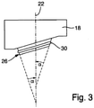
- FIG. 3 a side view of a clamping space cover 18 according to a second embodiment is shown. In the following, only the differences to the figure part (a) of the figure 2 described.
- the sealing surface 26.1 of the clamping space cover 18 formed by the outer surface of the connecting section 24 runs at an angle a to the central axis 22. Accordingly, the sealing surface 26.2 of the clamping space base 16 must also run at the same angle or at an angle that differs only slightly from the central axis 22.
Landscapes
- Physics & Mathematics (AREA)
- General Physics & Mathematics (AREA)
- Connector Housings Or Holding Contact Members (AREA)
- Measuring Fluid Pressure (AREA)
Abstract
Description
- Die Erfindung betrifft ein Sensorgehäuse umfassend ein Kopfteil mit einem Sensorraum zur Aufnahme eines Sensors und ein Anschlussteil mit einem Klemmraum zur Aufnahme eines Klemmanschlussblocks.
- Eine typische Bauform von Sensoren, wie induktiven oder kapazitativen Näherungssensoren, umfasst ein zweiteiliges Gehäuse. Der Sensor ist in einem Kopfteil angeordnet und in einem Anschlussteil wird eine Kontaktiervorrichtung, z.B. ein Klemmanschlussblock, zum Anschließen eines von außen kommenden Kabels angeordnet. Das Anschlussteil bzw. der von dem Anschlussteil umfasste Raum wird daher häufig auch als Klemmraum bezeichnet.
- Der Sensor in dem Kopfteil ist durch elektrische Verbindungen mit der Kontaktiervorrichtung verbunden, wofür das Kopfteil und das Anschlussteil entsprechende Durchgangsöffnungen und gegebenenfalls weitere Kontaktiervorrichtungen, wie z.B. Kontaktstifte, umfassen.
- Um einen Zugang zu dem Klemmraum zu ermöglichen, besteht das Anschlussteil typischerweise aus einem Unterteil und einem Deckel. Bekannt ist, das Unterteil und den Deckel entlang von senkrecht zu einer Fügerichtung verlaufenden Fügeflächen zusammenzusetzen. Ferner ist bekannt, zu Abdichtungszwecken auf einer der Fügeflächen eine umlaufende Dichtung, z.B. einen Gummiring oder eine umlaufende Flachdichtung, anzuordnen. Verschiedene Ausführungen zu Dichtvorrichtungen sind aus Haas, W: Grundlehrgang Dichtungstechnik. 2009-07-20. URL: https://www.ima.unistuttgart.de/dokumente/forschung/dichtungstechnik/skript_dichtungstechnik. pdf, bekannt.
- Einen entsprechenden Aufbau weisen beispielsweise der induktive Näherungssensors NBB20-U1-UU oder der kapazitiven Sensors CJ15+U1+A2 der Fa. Pepperl + Fuchs AG auf. Die Verbindung zwischen dem Deckel und dem Unterteil wird durch insgesamt drei Schrauben fixiert.
- Auch die Standardbauform der Baureihe IQ40 der Fa. SICK AG ist ähnlich aufgebaut.
- Nachteilig an diesem Aufbau ist, dass die Belastung bzw. die auf die Dichtung wirkende Kraft direkt von der Schraubverbindung abhängt. Hierdurch besteht außerdem die Gefahr, dass die Kraft entlang der Dichtung deutlich variiert.
- Vor diesem Hintergrund besteht die Aufgabe der Erfindung darin, eine Vorrichtung anzugeben, die den Stand der Technik weiterbildet.
- Insbesondere soll ein Sensorgehäuse mit einem zuverlässigen und möglichst Benutzer-unabhängigen und werkzeuglos bedienbaren Mechanismus für das Verbinden und Abdichten zwischen dem Deckel und Unterteil des Anschlussteils bereitgestellt werden.
- Die Aufgabe wird durch eine Vorrichtung mit den Merkmalen des Patentanspruchs 1 gelöst. Vorteilhafte Ausgestaltungen der Erfindung sind Gegenstand von Unteransprüchen.
- Gemäß dem Gegenstand der Erfindung wird ein Sensorgehäuse bereitgestellt, umfassend ein Kopfteil mit einem Sensorraum zur Aufnahme eines Sensors und ein an das Kopfteil angrenzendes Anschlussteil mit einem Klemmraum zur Aufnahme eines Klemmanschlussblocks, wobei das Kopfteil in einer an das Anschlussteil angrenzenden Rückwand eine Durchgangsöffnung zur Durchführung von elektrischen Verbindungen z.B.: Kabelund/oder Steckerdurchführung in den Sensorraum aufweist.
- Das Anschlussteil umfasst ein Klemmraumunterteil und einen Klemmraumdeckel, wobei das Klemmraumunterteil und der Klemmraumdeckel in einer Schließrichtung zusammengesetzt sind, so dass das Klemmraumunterteil und der Klemmraumdeckel aneinander angrenzen und den Klemmraum umschließen, der Klemmraumdeckel mittels eines Verbindungsmittels mit dem Kopfteil verbunden ist.
- Der Klemmraumdeckel weist eine an die Rückwand des Kopfteils angrenzende Seitenwand mit einer mit der Durchgangsöffnung des Kopfteils zumindest überlappenden Durchgangsöffnung zur Durchführung von elektrischen Verbindungen z.B.: Kabel- und/oder Steckerdurchführung von dem Sensorraum in den Klemmraum auf.
- Das Klemmraumunterteil weist eine Seitenwand mit einer Eingangsöffnung zur Kabel- und/oder Steckerdurchführung auf.
- Der Klemmraumdeckel und das Klemmraumunterteil weisen jeweils eine Dichtfläche auf, wobei die Dichtflächen einander zugewandt sind und parallel oder in einem Winkel von höchstens 3° oder höchstens 1,5° zueinander verlaufen.
- Die Dichtflächen verlaufen außerdem jeweils entlang einer geschlossen Kurve um eine parallel zu der Schließrichtung verlaufende Mittelachse des Anschlussteils herum und in einem Winkel von mindestens 0° und höchstens 45° oder höchstens 30° oder höchstens 20° zu der Längsachse, so dass ein Abstand zwischen jeder Dichtfläch́e und der Längsachse in Schließrichtung konstant ist oder abnimmt.
- Zwischen der Dichtfläche des Klemmraumdeckels und der Dichtfläche des Klemmraumunterteils ist ein umlaufendes Dichtelement zum Abdichten des Klemmraums angeordnet.
- Es versteht sich, dass die Begriffe Klemmraumunterteil und Klemmraumdeckel keine Ausrichtung des Anschlussteils bzw. keine Position/Ausrichtung der beiden Teile des Anschlussteils vorgeben. Die Begriffe dienen lediglich zur Unterscheidung bzw. zur Kennzeichnung der beiden Teile des zweiteiligen Anschlussteils.
- Es versteht sich auch, dass der Klemmraumdeckel und das Klemmraumunterteil jeweils Kanten und/oder Flächen aufweisen, entlang derer sie zusammengesetzt bzw. zusammengefügt werden können.
- Der aufzunehmende Klemmanschlussblock ist beispielsweise als separates Bauteil ausgebildet und in dem Klemmraum anordenbar. Alternativ ist der Klemmanschlussblock beispielsweise mit dem Klemmraumunterteil einstückig ausgebildet.
- Die Fügeflächen des Klemmraumdeckels liegen nach dem Fügen auf den Fügeflächen des Klemmraumunterteils auf, so dass der Klemmraumdeckel und das Klemmraumunterteil den Klemmraum bis auf die Öffnungen zur Durchführung von elektrischen Verbindungen wie z.B.: Kabel- und/oder Steckerdurchführungen umschließen.
- Als Dichtfläche werden Flächen bezeichnet, die nach dem Zusammensetzen nicht wie Fügeflächen aneinander anliegen, sondern durch ein Dichtelement zueinander beabstandet sind.
- Es versteht sich weiter, dass die Schließrichtung, also die Richtung in der der Klemmraumdeckel auf das Klemmraumunterteil aufgesetzt wird oder vice versa, und die Ausrichtung der Füge- und Dichtflächen einander bedingen. Insbesondere sind Hinterschneidungen hinsichtlich der Schließrichtung zu vermeiden.
- In einer besonders einfachen Ausführungsform besteht das Anschlussteil aus einem quaderförmigen Körper mit einem im Wesentlichen zylinderförmigen Hohlraum als Klemmraum, z.B. mit einer ovalen Grundfläche, wobei das Klemmraumunterteil die untere Hälfte des Körpers, der Klemmraumdeckel die obere Hälfte des Körpers umfasst.
- Insbesondere umfassen Klemmraumdeckel und Klemmraumunterteil jeweils als Vertiefung einen Teil des Klemmraums. Die Trenn- oder Schnittflächen, also die aneinander angrenzenden Kantenflächen der die zylinderförmige Ausnehmung umgebenden Seitenwände, bilden die Fügeflächen.
- Die Dichtflächen bilden in einer besonders einfachen Ausführungsform einen oberen Randabschnitt der Innenfläche der Vertiefung im Klemmraumunterteil einerseits und eine Außenfläche eines in die Vertiefung des Klemmraumunterteils hineinragenden Verbindungsteils des Klemmraumdeckels, wobei der Verbindungsabschnitt als ein dünner Wandabschnitt in Verlängerung der Vertiefung über die weitere Seitenflächen des Klemmraumdeckels hinausragt.
- Es versteht sich, dass alternativ ebenso einfach ein Verbindungsteil an dem Klemmraumunterteil angeordnet ist und zum Abdichten in die Vertiefung des Klemmraumdeckels hineinragt.
- Durch Dichtflächen, die parallel oder zumindest in einem spitzen Winkel verlaufen, wirkt das Dichtelement insbesondere radial zu der Mittelachse. Die Dichtwirkung ist dadurch unabhängiger von einer in Schließrichtung, also parallel zu der Mittelachse wirkenden Kraft zum Verschließen des Anschlussteils, z.B. durch Verschrauben der beiden Bauteile.
- Insbesondere ist die Wirkung des Dichtelements damit unabhängig von einem Anzugsmoment einer Verschraubung und damit auch unabhängig von der Handhabung bzw. dem Anwender.
- Die auf das Dichtelement wirkende Anpresskraft ist dagegen abhängig von den Abmessungen des Gehäuses, insbesondere der Dichtflächen, und kann dadurch gut reproduziert werden.
- Darüber hinaus werden Spannungsspitzen, insbesondere punktuell auftretende Spannungsspitzen, z.B. in der unmittelbaren Umgebung einer Befestigungsschraube, vermieden, wodurch auch lokale Veränderungen des Dichtelements, z.B. aufgrund von plastischer Verformung, vermieden werden. Die Qualität der Dichtwirkung des erfindungsgemäßen Sensorgehäuses wird so über eine lange Gebrauchsdauer aufrechterhalten.
- Gemäß einer ersten Ausführungsform weist die Dichtfläche des Klemmraumdeckels oder die Dichtfläche des Klemmraumunterteils eine Nut zur Aufnahme des Dichtelements auf.
- In einer anderen Ausführungsform ist jede Dichtfläche als Mantelfläche eines Zylinders oder eines Kegelstumpfs ausgebildet.
- Es versteht sich, dass jede Zylinderform oder Kegelstumpfform umfasst ist. Insbesondere kann es sich sowohl um einen geraden oder schiefen Zylinder bzw. Kegelstumpf handeln und die Grundfläche eine beliebige Form aufweisen. Gemäß einer Weiterbildung ist die Grundfläche des Zylinders oder Kegelstumpfs abgerundet, bevorzugt oval.
- Die Grundfläche ist senkrecht oder in einem Winkel zu der Mittelachse ausgerichtet. Ein abgerundeter stetiger innerer bzw. äußerer Umfang der Dichtflächen ermöglicht es, mit einem dem Umfang folgenden radialen Dichtelement eine gute Dichtigkeit zu erreichen.
- Insbesondere wirkt durch diese Form eine möglichst gleichmäßige Anpresskraft auf das Dichtelement, wobei die Anpresskraft im Wesentlichen von den Abmessungen bzw. der Form der Gehäuseteile abhängt.
- Gemäß einer weiteren Ausführungsform umschließen die Dichtflächen in einer Projektion entlang der Mittelachse jeweils eine Fläche, wobei die Fläche kreisförmig oder oval ausgebildet ist.
- In einer anderen Weiterbildung ist eine der Dichtflächen als Verlängerung einer Innenfläche des Klemmraums ausgebildet. Anders ausgedrückt, die Innenfläche des Klemmraums bzw. ein oberer Randabschnitt der Innenfläche einer Ausnehmung in dem Klemmraumunterteil oder dem Klemmraumoberteil, dient als Dichtfläche, wobei die Ausnehmung einen Teil des Klemmraums ausbildet.
- Gemäß einer weiteren Weiterbildung entspricht das Sensorgehäuse dem IP 68 Standard oder dem IP 69K Standard.
- In einer anderen Ausführungsform weist der induktive oder kapazitive Näherungssensor ein Sensorgehäuse gemäß einem der vorangegangenen Ansprüche auf.
- In einer Weiterbildung ist im dem Kopfteil wenigstens ein Sensorbauelement angeordnet. Vorzugsweise umfasst das Sensorbauelement einen induktiven und / oder kapazitiven und oder optischen und oder einen Ultraschallsensor. Vorzugsweise besteht das Sensorbauelement aus einen induktiven und / oder kapazitiven und oder optischen und oder einen Ultraschallsensor.
- Die Erfindung wird nachfolgend unter Bezugnahme auf die Zeichnungen näher erläutert. Hierbei werden gleichartige Teile mit identischen Bezeichnungen beschriftet. Die dargestellten Ausführungsformen sind stark schematisiert, d.h. die Abstände und die lateralen und die vertikalen Erstreckungen sind nicht maßstäblich und weisen, sofern nicht anders angegeben, auch keine ableitbaren geometrischen Relationen zueinander auf. Darin zeigen, die
- Figur 1
- eine seitliche Ansicht einer ersten erfindungsgemäße Ausführungsform eines Sensorgehäuses in einem geschlossenen Zustand,
- Figur 2
- eine Ansicht eines geöffneten Anschlussteils,
- Figur 3
- eine seitliche Ansicht eines Klemmraumdeckels gemäß einer zweiten Ausführungsform.
- Die Abbildung der
Figur 1 zeigt eine seitliche Ansicht einer ersten erfindungsgemäßen Ausführungsform eines Sensorgehäuse 10, umfassend ein Kopfteil 12 mit einem Sensorraum (gestrichelt) zur Aufnahme eines Sensors und ein an das Kopfteil 12 angrenzendes Anschlussteil 14 mit einem Klemmraum (gestrichelt) zur Aufnahme eines Klemmanschlussblocks. - Das Anschlussteil besteht aus einem Klemmraumunterteil 16 und einem Klemmraumdeckel 18, die aneinander angrenzen, den Klemmraum umschließen. Das Klemmraumunterteil 16 und der Klemmraumdeckel 18 können für einen Zugang zu dem Klemmraum durch eine Bewegung entgegen einer Schließrichtung 20 getrennt werden.
- Nur gestrichelt angedeutet sind die Durchgangsöffnungen für die elektrischen Verbindungen wie z.B.: Kabel- und/oder Steckerdurchführung zwischen dem Sensorraum und dem Klemmraum bzw. von außen in den Klemmraum.
- Hierfür weist eine an das Anschlussteil 14 angrenzende Rückwand des Kopfteils 12 eine erste Durchgangsöffnung und eine an das Kopfteil 12 angrenzende Seitenwand des Klemmraumdeckels 18 eine mit der ersten Durchgangsöffnung zumindest überlappende zweite Durchgangsöffnung auf.
- Außerdem weist eine Seitenwand des Klemmraumunterteils 16 eine Eingangsöffnung zur Kabel- und/oder Steckerdurchführung von außen in den Klemmraum auf.
- Das Kopfteil 12 ist mittels eines nicht dargestellten Verbindungsmittels mit dem Klemmraumdeckel 18 verbunden.
- In der Abbildung der
Figur 2 ist das Anschlussteil 14 in geöffnetem Zustand gezeigt, wobei der Klemmraumdeckel 18 in einer Schnittansicht (Abbildungsteil a) und das Klemmraumunterteil 16 in einer Aufsicht (Abbildungsteil b) gezeigt ist. - Der Klemmraumdeckel 18 weist eine Ausnehmung 18.1 mit einer parallel zu der Schließrichtung 20 verlaufenden Mittelachse 22 und in Verlängerung der Ausnehmung einen Verbindungsabschnitt 24 auf.
- Eine von der Mittelachse 22 abgewandte Außenfläche des Verbindungabschnitts 24 bildet eine Dichtfläche 26.1 des Klemmraumdeckels 18. Die Dichtfläche 26.1 des Klemmraumdeckels 18 verläuft parallel zu der Mittelachse 22, umschließt die Mittelachse 22 vollständig und weist eine Nut 28 auf. In der Nut 28 ist ein Dichtelement 30 angeordnet.
- Das Klemmraumunterteil 16 weist eine zylinderförmige Ausnehmung mit einer ovalen Grundfläche und einer senkrecht zu der Mittelachse 22 verlaufenden Mantelfläche auf. Ein oberer Randbereich der Innenfläche der Ausnehmung bildet eine Dichtfläche 26.2 des Klemmraumunterteils 16 aus.
- In der Abbildung der
Figur 3 ist eine seitliche Ansicht eines Klemmraumdeckels 18 gemäß einer zweiten Ausführungsform dargestellt. Im Folgenden werden nur die Unterschiede zu dem Abbildungsteil (a) derFigur 2 beschrieben. - Die durch die Außenfläche des Verbindungsabschnitts 24 gebildete Dichtfläche 26.1 des Klemmraumdeckels 18 verläuft in einem Winkel a zu der Mittelachse 22. Entsprechend muss auch die Dichtfläche 26.2 des Klemmraumunterteils 16 in demselben Winkel oder einem nur geringfügig abweichenden Winkel zu der Mittelachse 22 verlaufen.
Claims (7)
- Sensorgehäuse (10), umfassend ein Kopfteil (12) mit einem Sensorraum zur Aufnahme eines Sensors und ein an das Kopfteil (12) angrenzendes Anschlussteil (14) mit einem Klemmraum zur Aufnahme eines Klemmanschlussblocks, wobei- das Kopfteil (12) in einer an das Anschlussteil (14) angrenzenden Rückwand eine Durchgangsöffnung zur Durchführung von elektrischen Verbindungen wie z.B.: Kabel- und/oder Steckerdurchführungen in den Sensorraum aufweist,- das Anschlussteil (14) ein Klemmraumunterteil (16) und einen Klemmraumdeckel (18) umfasst,- das Klemmraumunterteil (16) und der Klemmraumdeckel (18) in einer Schließrichtung (20) zusammengesetzt sind, so dass- das Klemmraumunterteil (16) und der Klemmraumdeckel (18) aneinander angrenzen und den Klemmraum umschließen,- der Klemmraumdeckel (18) mittels eines Verbindungsmittels mit dem Kopfteil (12) verbunden ist,- der Klemmraumdeckel (18) eine an die Rückwand des Kopfteils (12) angrenzende Seitenwand mit einer mit der Durchgangsöffnung des Kopfteils (12) zumindest überlappenden Durchgangsöffnung zur Durchführung von elektrischen Verbindungen wie z.B.: Kabelund/oder Steckerdurchführungen von dem Sensorraum in den Klemmraum aufweist,- das Klemmraumunterteil (16) eine Seitenwand mit einer Eingangsöffnung zur Kabel- und/oder Steckerdurchführung aufweist,
dadurch gekennzeichnet, dass- der Klemmraumdeckel (18) und das Klemmraumunterteil (16) jeweils eine Dichtfläche (26) aufweisen, wobei- die Dichtflächen (26) einander zugewandt sind,- die Dichtflächen (26) zueinander parallel oder zueinander in einem Winkel von höchstens 3° verlaufen,- die Dichtflächen (26) jeweils entlang einer geschlossen Kurve um eine parallel zu der Schließrichtung (20) verlaufende Mittelachse (22) des Anschlussteils (14) herum verlaufen,- die Dichtflächen (26) jeweils in einem Winkel von mindestens 0° und höchstens 45° zu der Mittelachse (22) verlaufen, so dass- ein Abstand zwischen jeder Dichtfläche (26) und der Mittelachse in Schließrichtung (20) konstant ist oder abnimmt und- zwischen der Dichtfläche (26) des Klemmraumdeckels (18) und der Dichtfläche (26) des Klemmraumunterteils (16) ein umlaufendes Dichtelement zum Abdichten des Klemmraums angeordnet ist. - Sensorgehäuse nach Anspruch 1, dadurch gekennzeichnet, dass die Dichtfläche (26) des Klemmraumdeckels (18) oder die Dichtfläche (26) des Klemmraumunterteils (16) eine Nut zur Aufnahme des Dichtelements aufweist.
- Sensorgehäuse nach Anspruch 1 oder 2, dadurch gekennzeichnet, dass jede Dichtfläche (26) als Mantelfläche eines Zylinders oder eines Kegelstumpfs ausgebildet ist.
- Sensorgehäuse nach einem der vorangegangenen Ansprüche, dadurch gekennzeichnet, dass die Dichtflächen (26) jeweils in einer Projektion entlang der Mittelachse (22) eine Fläche umschließen, wobei die Fläche kreisförmig oder oval ausgebildet ist.
- Sensorgehäuse nach einem der vorangegangenen Ansprüche, dadurch gekennzeichnet, dass eine der Dichtflächen (26) als Verlängerung einer Innenfläche des Klemmraums ausgebildet ist.
- Sensorgehäuse nach einem der vorangegangenen Ansprüche, dadurch gekennzeichnet, dass das Sensorgehäuse dem IP 68 Standard oder dem IP 69K Standard entspricht.
- Induktiver Näherungssensor oder kapazitiver, dadurch gekennzeichnet, dass der Näherungssensor ein Sensorgehäuse gemäß einem der vorangegangenen Ansprüche aufweist.
Applications Claiming Priority (1)
| Application Number | Priority Date | Filing Date | Title |
|---|---|---|---|
| DE102020005216.9A DE102020005216A1 (de) | 2020-08-26 | 2020-08-26 | Sensorgehäuse |
Publications (2)
| Publication Number | Publication Date |
|---|---|
| EP3961160A1 true EP3961160A1 (de) | 2022-03-02 |
| EP3961160B1 EP3961160B1 (de) | 2023-07-19 |
Family
ID=77274641
Family Applications (1)
| Application Number | Title | Priority Date | Filing Date |
|---|---|---|---|
| EP21000220.0A Active EP3961160B1 (de) | 2020-08-26 | 2021-08-09 | Sensorgehäuse |
Country Status (2)
| Country | Link |
|---|---|
| EP (1) | EP3961160B1 (de) |
| DE (1) | DE102020005216A1 (de) |
Citations (6)
| Publication number | Priority date | Publication date | Assignee | Title |
|---|---|---|---|---|
| US4090091A (en) * | 1976-03-17 | 1978-05-16 | Electro Corporation | Housing and control circuit assembly with sensing element |
| DE2819782A1 (de) * | 1978-05-05 | 1979-11-08 | Pepperl & Fuchs | Naeherungsinitiator |
| US4225748A (en) * | 1977-06-02 | 1980-09-30 | Robert Buck | Switching device, especially for electronic contactless switches, e.g. proximity switches |
| DE2915109A1 (de) * | 1979-04-12 | 1981-01-22 | Pepperl & Fuchs | Naeherungsinitiator |
| US4654471A (en) * | 1984-04-25 | 1987-03-31 | Omron Tateisi Electronics Co. | Electronic switch |
| DE202014103822U1 (de) * | 2014-08-18 | 2014-09-01 | Balluff Gmbh | Verschlusskappe für ein Sensorgehäuse und Sensorset |
-
2020
- 2020-08-26 DE DE102020005216.9A patent/DE102020005216A1/de active Pending
-
2021
- 2021-08-09 EP EP21000220.0A patent/EP3961160B1/de active Active
Patent Citations (6)
| Publication number | Priority date | Publication date | Assignee | Title |
|---|---|---|---|---|
| US4090091A (en) * | 1976-03-17 | 1978-05-16 | Electro Corporation | Housing and control circuit assembly with sensing element |
| US4225748A (en) * | 1977-06-02 | 1980-09-30 | Robert Buck | Switching device, especially for electronic contactless switches, e.g. proximity switches |
| DE2819782A1 (de) * | 1978-05-05 | 1979-11-08 | Pepperl & Fuchs | Naeherungsinitiator |
| DE2915109A1 (de) * | 1979-04-12 | 1981-01-22 | Pepperl & Fuchs | Naeherungsinitiator |
| US4654471A (en) * | 1984-04-25 | 1987-03-31 | Omron Tateisi Electronics Co. | Electronic switch |
| DE202014103822U1 (de) * | 2014-08-18 | 2014-09-01 | Balluff Gmbh | Verschlusskappe für ein Sensorgehäuse und Sensorset |
Also Published As
| Publication number | Publication date |
|---|---|
| EP3961160B1 (de) | 2023-07-19 |
| DE102020005216A1 (de) | 2022-03-03 |
Similar Documents
| Publication | Publication Date | Title |
|---|---|---|
| EP1843441A2 (de) | Dichtung für eine Gehäusedurchführung für ein Kabel | |
| EP2764591A2 (de) | Kabeldurchführung und verfahren zur montage einer kabeldurchführung | |
| DE3614198C2 (de) | ||
| EP2098838B1 (de) | Füllstandmessgerät | |
| EP1698877B1 (de) | Differenzdrucksensor-Anordnung und zugehöriger Differenzdrucksensor | |
| WO2004008820A1 (de) | Verdrehsicherung, insbesondere für ein messumformergehäuse | |
| WO2016041904A1 (de) | Gehäuse zur aufnahme elektrischer und/oder elektronischer bauteile, elektronisches steuergerät und verfahren zur herstellung derselben | |
| EP3961160B1 (de) | Sensorgehäuse | |
| DE10313828A1 (de) | Kraftmesszelle | |
| DE4439567A1 (de) | Korrosionsschutzkappe für eine Verschraubung | |
| DE4340051A1 (de) | Flanschverbindung | |
| DE102004053083A1 (de) | Abstreif- und/oder Dichtungselement sowie Verfahren zum Abdichten eines Kolbens und Spann-und/oder Stützelement | |
| EP0727850B1 (de) | Einrichtung zur Festlegung eines elektrischen oder elektronischen Bauteiles mit einem Gehäuse | |
| EP1634048B1 (de) | Drucksensor-anordnung | |
| EP1091465B1 (de) | Kabeldurchführung | |
| EP1740903A2 (de) | Wegmess-vorrichtung | |
| DE19600260C1 (de) | Innenscharnier zur Unterbringung im Verschraubungskanal von Gehäusen | |
| DE102011012883A1 (de) | Anschlussbodendose | |
| DE69215572T2 (de) | Einrichtung zum Erfassen der Änderung im Innendruck eines Zylinders | |
| DE2717951C2 (de) | Wanddurchführung für Kabel, Leitungen, Rohre o.dgl. | |
| EP3997768A1 (de) | Kabeldurchführung für einen steuerungsschrank | |
| DE20205485U1 (de) | Elektronik-Baugruppe, insbesondere Sensor | |
| DE3546435C2 (de) | Quetschverbinder | |
| EP0926351A2 (de) | Hydraulisches Steuergerät mit mehrteiligem Gehäuse | |
| DE202019101493U1 (de) | Hydraulikzylinder |
Legal Events
| Date | Code | Title | Description |
|---|---|---|---|
| PUAI | Public reference made under article 153(3) epc to a published international application that has entered the european phase |
Free format text: ORIGINAL CODE: 0009012 |
|
| STAA | Information on the status of an ep patent application or granted ep patent |
Free format text: STATUS: REQUEST FOR EXAMINATION WAS MADE |
|
| 17P | Request for examination filed |
Effective date: 20220126 |
|
| AK | Designated contracting states |
Kind code of ref document: A1 Designated state(s): AL AT BE BG CH CY CZ DE DK EE ES FI FR GB GR HR HU IE IS IT LI LT LU LV MC MK MT NL NO PL PT RO RS SE SI SK SM TR |
|
| GRAP | Despatch of communication of intention to grant a patent |
Free format text: ORIGINAL CODE: EPIDOSNIGR1 |
|
| STAA | Information on the status of an ep patent application or granted ep patent |
Free format text: STATUS: GRANT OF PATENT IS INTENDED |
|
| INTG | Intention to grant announced |
Effective date: 20230411 |
|
| GRAS | Grant fee paid |
Free format text: ORIGINAL CODE: EPIDOSNIGR3 |
|
| GRAA | (expected) grant |
Free format text: ORIGINAL CODE: 0009210 |
|
| STAA | Information on the status of an ep patent application or granted ep patent |
Free format text: STATUS: THE PATENT HAS BEEN GRANTED |
|
| AK | Designated contracting states |
Kind code of ref document: B1 Designated state(s): AL AT BE BG CH CY CZ DE DK EE ES FI FR GB GR HR HU IE IS IT LI LT LU LV MC MK MT NL NO PL PT RO RS SE SI SK SM TR |
|
| REG | Reference to a national code |
Ref country code: GB Ref legal event code: FG4D Free format text: NOT ENGLISH |
|
| REG | Reference to a national code |
Ref country code: CH Ref legal event code: EP |
|
| REG | Reference to a national code |
Ref country code: DE Ref legal event code: R096 Ref document number: 502021001007 Country of ref document: DE |
|
| REG | Reference to a national code |
Ref country code: IE Ref legal event code: FG4D Free format text: LANGUAGE OF EP DOCUMENT: GERMAN |
|
| REG | Reference to a national code |
Ref country code: LT Ref legal event code: MG9D |
|
| REG | Reference to a national code |
Ref country code: NL Ref legal event code: MP Effective date: 20230719 |
|
| PG25 | Lapsed in a contracting state [announced via postgrant information from national office to epo] |
Ref country code: NL Free format text: LAPSE BECAUSE OF FAILURE TO SUBMIT A TRANSLATION OF THE DESCRIPTION OR TO PAY THE FEE WITHIN THE PRESCRIBED TIME-LIMIT Effective date: 20230719 |
|
| PG25 | Lapsed in a contracting state [announced via postgrant information from national office to epo] |
Ref country code: GR Free format text: LAPSE BECAUSE OF FAILURE TO SUBMIT A TRANSLATION OF THE DESCRIPTION OR TO PAY THE FEE WITHIN THE PRESCRIBED TIME-LIMIT Effective date: 20231020 |
|
| PG25 | Lapsed in a contracting state [announced via postgrant information from national office to epo] |
Ref country code: IS Free format text: LAPSE BECAUSE OF FAILURE TO SUBMIT A TRANSLATION OF THE DESCRIPTION OR TO PAY THE FEE WITHIN THE PRESCRIBED TIME-LIMIT Effective date: 20231119 |
|
| PG25 | Lapsed in a contracting state [announced via postgrant information from national office to epo] |
Ref country code: SE Free format text: LAPSE BECAUSE OF FAILURE TO SUBMIT A TRANSLATION OF THE DESCRIPTION OR TO PAY THE FEE WITHIN THE PRESCRIBED TIME-LIMIT Effective date: 20230719 Ref country code: RS Free format text: LAPSE BECAUSE OF FAILURE TO SUBMIT A TRANSLATION OF THE DESCRIPTION OR TO PAY THE FEE WITHIN THE PRESCRIBED TIME-LIMIT Effective date: 20230719 Ref country code: PT Free format text: LAPSE BECAUSE OF FAILURE TO SUBMIT A TRANSLATION OF THE DESCRIPTION OR TO PAY THE FEE WITHIN THE PRESCRIBED TIME-LIMIT Effective date: 20231120 Ref country code: NO Free format text: LAPSE BECAUSE OF FAILURE TO SUBMIT A TRANSLATION OF THE DESCRIPTION OR TO PAY THE FEE WITHIN THE PRESCRIBED TIME-LIMIT Effective date: 20231019 Ref country code: LV Free format text: LAPSE BECAUSE OF FAILURE TO SUBMIT A TRANSLATION OF THE DESCRIPTION OR TO PAY THE FEE WITHIN THE PRESCRIBED TIME-LIMIT Effective date: 20230719 Ref country code: LT Free format text: LAPSE BECAUSE OF FAILURE TO SUBMIT A TRANSLATION OF THE DESCRIPTION OR TO PAY THE FEE WITHIN THE PRESCRIBED TIME-LIMIT Effective date: 20230719 Ref country code: IS Free format text: LAPSE BECAUSE OF FAILURE TO SUBMIT A TRANSLATION OF THE DESCRIPTION OR TO PAY THE FEE WITHIN THE PRESCRIBED TIME-LIMIT Effective date: 20231119 Ref country code: HR Free format text: LAPSE BECAUSE OF FAILURE TO SUBMIT A TRANSLATION OF THE DESCRIPTION OR TO PAY THE FEE WITHIN THE PRESCRIBED TIME-LIMIT Effective date: 20230719 Ref country code: GR Free format text: LAPSE BECAUSE OF FAILURE TO SUBMIT A TRANSLATION OF THE DESCRIPTION OR TO PAY THE FEE WITHIN THE PRESCRIBED TIME-LIMIT Effective date: 20231020 Ref country code: FI Free format text: LAPSE BECAUSE OF FAILURE TO SUBMIT A TRANSLATION OF THE DESCRIPTION OR TO PAY THE FEE WITHIN THE PRESCRIBED TIME-LIMIT Effective date: 20230719 |
|
| PG25 | Lapsed in a contracting state [announced via postgrant information from national office to epo] |
Ref country code: PL Free format text: LAPSE BECAUSE OF FAILURE TO SUBMIT A TRANSLATION OF THE DESCRIPTION OR TO PAY THE FEE WITHIN THE PRESCRIBED TIME-LIMIT Effective date: 20230719 |
|
| PG25 | Lapsed in a contracting state [announced via postgrant information from national office to epo] |
Ref country code: LU Free format text: LAPSE BECAUSE OF NON-PAYMENT OF DUE FEES Effective date: 20230809 |
|
| REG | Reference to a national code |
Ref country code: DE Ref legal event code: R097 Ref document number: 502021001007 Country of ref document: DE |
|
| PG25 | Lapsed in a contracting state [announced via postgrant information from national office to epo] |
Ref country code: ES Free format text: LAPSE BECAUSE OF FAILURE TO SUBMIT A TRANSLATION OF THE DESCRIPTION OR TO PAY THE FEE WITHIN THE PRESCRIBED TIME-LIMIT Effective date: 20230719 |
|
| PG25 | Lapsed in a contracting state [announced via postgrant information from national office to epo] |
Ref country code: SM Free format text: LAPSE BECAUSE OF FAILURE TO SUBMIT A TRANSLATION OF THE DESCRIPTION OR TO PAY THE FEE WITHIN THE PRESCRIBED TIME-LIMIT Effective date: 20230719 Ref country code: RO Free format text: LAPSE BECAUSE OF FAILURE TO SUBMIT A TRANSLATION OF THE DESCRIPTION OR TO PAY THE FEE WITHIN THE PRESCRIBED TIME-LIMIT Effective date: 20230719 Ref country code: LU Free format text: LAPSE BECAUSE OF NON-PAYMENT OF DUE FEES Effective date: 20230809 Ref country code: ES Free format text: LAPSE BECAUSE OF FAILURE TO SUBMIT A TRANSLATION OF THE DESCRIPTION OR TO PAY THE FEE WITHIN THE PRESCRIBED TIME-LIMIT Effective date: 20230719 Ref country code: EE Free format text: LAPSE BECAUSE OF FAILURE TO SUBMIT A TRANSLATION OF THE DESCRIPTION OR TO PAY THE FEE WITHIN THE PRESCRIBED TIME-LIMIT Effective date: 20230719 Ref country code: DK Free format text: LAPSE BECAUSE OF FAILURE TO SUBMIT A TRANSLATION OF THE DESCRIPTION OR TO PAY THE FEE WITHIN THE PRESCRIBED TIME-LIMIT Effective date: 20230719 Ref country code: SK Free format text: LAPSE BECAUSE OF FAILURE TO SUBMIT A TRANSLATION OF THE DESCRIPTION OR TO PAY THE FEE WITHIN THE PRESCRIBED TIME-LIMIT Effective date: 20230719 Ref country code: MC Free format text: LAPSE BECAUSE OF FAILURE TO SUBMIT A TRANSLATION OF THE DESCRIPTION OR TO PAY THE FEE WITHIN THE PRESCRIBED TIME-LIMIT Effective date: 20230719 |
|
| REG | Reference to a national code |
Ref country code: BE Ref legal event code: MM Effective date: 20230831 |
|
| REG | Reference to a national code |
Ref country code: IE Ref legal event code: MM4A |
|
| PLBE | No opposition filed within time limit |
Free format text: ORIGINAL CODE: 0009261 |
|
| STAA | Information on the status of an ep patent application or granted ep patent |
Free format text: STATUS: NO OPPOSITION FILED WITHIN TIME LIMIT |
|
| PG25 | Lapsed in a contracting state [announced via postgrant information from national office to epo] |
Ref country code: IT Free format text: LAPSE BECAUSE OF FAILURE TO SUBMIT A TRANSLATION OF THE DESCRIPTION OR TO PAY THE FEE WITHIN THE PRESCRIBED TIME-LIMIT Effective date: 20230719 |
|
| 26N | No opposition filed |
Effective date: 20240422 |
|
| PG25 | Lapsed in a contracting state [announced via postgrant information from national office to epo] |
Ref country code: IE Free format text: LAPSE BECAUSE OF NON-PAYMENT OF DUE FEES Effective date: 20230809 |
|
| PG25 | Lapsed in a contracting state [announced via postgrant information from national office to epo] |
Ref country code: IE Free format text: LAPSE BECAUSE OF NON-PAYMENT OF DUE FEES Effective date: 20230809 Ref country code: SI Free format text: LAPSE BECAUSE OF FAILURE TO SUBMIT A TRANSLATION OF THE DESCRIPTION OR TO PAY THE FEE WITHIN THE PRESCRIBED TIME-LIMIT Effective date: 20230719 |
|
| PG25 | Lapsed in a contracting state [announced via postgrant information from national office to epo] |
Ref country code: BE Free format text: LAPSE BECAUSE OF NON-PAYMENT OF DUE FEES Effective date: 20230831 |
|
| PG25 | Lapsed in a contracting state [announced via postgrant information from national office to epo] |
Ref country code: BG Free format text: LAPSE BECAUSE OF FAILURE TO SUBMIT A TRANSLATION OF THE DESCRIPTION OR TO PAY THE FEE WITHIN THE PRESCRIBED TIME-LIMIT Effective date: 20230719 |
|
| PG25 | Lapsed in a contracting state [announced via postgrant information from national office to epo] |
Ref country code: BG Free format text: LAPSE BECAUSE OF FAILURE TO SUBMIT A TRANSLATION OF THE DESCRIPTION OR TO PAY THE FEE WITHIN THE PRESCRIBED TIME-LIMIT Effective date: 20230719 |
|
| PG25 | Lapsed in a contracting state [announced via postgrant information from national office to epo] |
Ref country code: CY Free format text: LAPSE BECAUSE OF FAILURE TO SUBMIT A TRANSLATION OF THE DESCRIPTION OR TO PAY THE FEE WITHIN THE PRESCRIBED TIME-LIMIT; INVALID AB INITIO Effective date: 20210809 |
|
| PG25 | Lapsed in a contracting state [announced via postgrant information from national office to epo] |
Ref country code: HU Free format text: LAPSE BECAUSE OF FAILURE TO SUBMIT A TRANSLATION OF THE DESCRIPTION OR TO PAY THE FEE WITHIN THE PRESCRIBED TIME-LIMIT; INVALID AB INITIO Effective date: 20210809 |
|
| PGFP | Annual fee paid to national office [announced via postgrant information from national office to epo] |
Ref country code: DE Payment date: 20250819 Year of fee payment: 5 |
|
| PGFP | Annual fee paid to national office [announced via postgrant information from national office to epo] |
Ref country code: FR Payment date: 20250821 Year of fee payment: 5 Ref country code: AT Payment date: 20251020 Year of fee payment: 5 |
|
| PGFP | Annual fee paid to national office [announced via postgrant information from national office to epo] |
Ref country code: CH Payment date: 20250901 Year of fee payment: 5 |
|
| PGFP | Annual fee paid to national office [announced via postgrant information from national office to epo] |
Ref country code: CZ Payment date: 20250729 Year of fee payment: 5 |