EP3960405A1 - Tischsäge - Google Patents
Tischsäge Download PDFInfo
- Publication number
- EP3960405A1 EP3960405A1 EP21199058.5A EP21199058A EP3960405A1 EP 3960405 A1 EP3960405 A1 EP 3960405A1 EP 21199058 A EP21199058 A EP 21199058A EP 3960405 A1 EP3960405 A1 EP 3960405A1
- Authority
- EP
- European Patent Office
- Prior art keywords
- section
- saw blade
- support
- saw
- underside
- Prior art date
- Legal status (The legal status is an assumption and is not a legal conclusion. Google has not performed a legal analysis and makes no representation as to the accuracy of the status listed.)
- Granted
Links
Images



Classifications
-
- B—PERFORMING OPERATIONS; TRANSPORTING
- B27—WORKING OR PRESERVING WOOD OR SIMILAR MATERIAL; NAILING OR STAPLING MACHINES IN GENERAL
- B27B—SAWS FOR WOOD OR SIMILAR MATERIAL; COMPONENTS OR ACCESSORIES THEREFOR
- B27B5/00—Sawing machines working with circular or cylindrical saw blades; Components or equipment therefor
- B27B5/16—Saw benches
- B27B5/22—Saw benches with non-feedable circular saw blade
- B27B5/24—Saw benches with non-feedable circular saw blade the saw blade being adjustable according to depth or angle of cut
-
- B—PERFORMING OPERATIONS; TRANSPORTING
- B27—WORKING OR PRESERVING WOOD OR SIMILAR MATERIAL; NAILING OR STAPLING MACHINES IN GENERAL
- B27B—SAWS FOR WOOD OR SIMILAR MATERIAL; COMPONENTS OR ACCESSORIES THEREFOR
- B27B25/00—Feeding devices for timber in saw mills or sawing machines; Feeding devices for trees
- B27B25/10—Manually-operated feeding or pressing accessories, e.g. pushers
-
- B—PERFORMING OPERATIONS; TRANSPORTING
- B27—WORKING OR PRESERVING WOOD OR SIMILAR MATERIAL; NAILING OR STAPLING MACHINES IN GENERAL
- B27B—SAWS FOR WOOD OR SIMILAR MATERIAL; COMPONENTS OR ACCESSORIES THEREFOR
- B27B27/00—Guide fences or stops for timber in saw mills or sawing machines; Measuring equipment thereon
- B27B27/04—Guide fences or stops for timber in saw mills or sawing machines; Measuring equipment thereon arranged perpendicularly to the plane of the saw blade
-
- B—PERFORMING OPERATIONS; TRANSPORTING
- B27—WORKING OR PRESERVING WOOD OR SIMILAR MATERIAL; NAILING OR STAPLING MACHINES IN GENERAL
- B27G—ACCESSORY MACHINES OR APPARATUS FOR WORKING WOOD OR SIMILAR MATERIALS; TOOLS FOR WORKING WOOD OR SIMILAR MATERIALS; SAFETY DEVICES FOR WOOD WORKING MACHINES OR TOOLS
- B27G19/00—Safety guards or devices specially adapted for wood saws; Auxiliary devices facilitating proper operation of wood saws
- B27G19/02—Safety guards or devices specially adapted for wood saws; Auxiliary devices facilitating proper operation of wood saws for circular saws
- B27G19/025—Safety guards or devices specially adapted for wood saws; Auxiliary devices facilitating proper operation of wood saws for circular saws with guards for tool
-
- B—PERFORMING OPERATIONS; TRANSPORTING
- B27—WORKING OR PRESERVING WOOD OR SIMILAR MATERIAL; NAILING OR STAPLING MACHINES IN GENERAL
- B27B—SAWS FOR WOOD OR SIMILAR MATERIAL; COMPONENTS OR ACCESSORIES THEREFOR
- B27B5/00—Sawing machines working with circular or cylindrical saw blades; Components or equipment therefor
- B27B5/16—Saw benches
- B27B5/22—Saw benches with non-feedable circular saw blade
- B27B5/24—Saw benches with non-feedable circular saw blade the saw blade being adjustable according to depth or angle of cut
- B27B5/243—Saw benches with non-feedable circular saw blade the saw blade being adjustable according to depth or angle of cut the saw blade being arranged underneath the work-table
Definitions
- the invention relates to a table saw.
- the present invention deals in particular with the task of reducing the probability of malfunctions and/or increasing operational reliability.
- the table saw includes a support structure having a support portion that provides a support surface for supporting a workpiece, and a saw blade that engages through an opening of the support portion such that at least a portion of the saw blade is below the support portion underside.
- the table saw further includes a housing assembly located below the support portion underside that encloses the portion of the saw blade located below the support portion underside. The saw blade, together with the housing arrangement, can be pivoted relative to the support section in order to set an angle between a cutting plane of the saw blade and the support surface.
- One object of the invention is to increase operational reliability.
- the object is achieved by a table saw according to claim 1.
- the table saw comprises a cover flap which closes a gap between the housing arrangement and the underside of the support section that occurs when the housing arrangement is pivoted covers so as to prevent a user of the table saw from reaching through the gap towards the saw blade. In this way, the operational reliability of the table saw can be increased.
- the cover flap is expediently mounted, in particular movable, on the housing arrangement and/or the support structure.
- the cover flap is preferably movably mounted on the housing arrangement and/or fixedly mounted on the support structure.
- the cover flap can be moved from a first position into a second position by pivoting the housing arrangement. In the first position, the cover flap is aligned parallel to the underside of the support section and/or in the second position it is aligned inclined about a horizontal axis to the underside of the support section.
- the support structure expediently has several legs, via which the support section can be supported relative to the ground. Between the legs there are free areas through which a user can reach under the underside of the support section.
- the table saw, in particular the support structure is thus to a certain extent unencapsulated and allows a user to reach under the support section in a simple manner.
- the invention also relates to a saw blade cover.
- the saw blade cover is designed in particular as a saw blade hood and comprises a cover body, which extends in a longitudinal direction and is made of a first material, for at least partially covering a saw blade of the table saw.
- the saw blade cover includes furthermore a contact area arranged on the face side of the cover body. The contact area is beveled relative to the longitudinal direction, so that a deflection of the cover body can be brought about by contact of the contact area with a workpiece brought up to the saw blade.
- An object of the invention is to modify the saw blade guard in such a way that the likelihood of malfunctions can be reduced.
- the object is achieved by a saw blade cover in which the contact area has a sliding section made from a second material, along which the workpiece can slide when it comes into contact with the contact area.
- the sliding section can prevent a workpiece from being in contact with the contact area in cuts into it and gets stuck in the contact area. Consequently, the possibility of malfunctions can be reduced.
- the first material may also be referred to as a cover body material, and the second material may also be referred to as a sliding portion material.
- the second material differs from the first material.
- the second material is expediently harder than the first material.
- the first material is in particular plastic and/or the second material is in particular metal, preferably aluminum.
- the sliding section is expediently in the form of a strip.
- the sliding section is preferably designed as an aluminum strip.
- the contact area and the sliding section are elongate.
- the sliding section expediently runs in the longitudinal direction of the contact area.
- the contact area is expediently a front contact surface.
- the sliding section is expediently present only in a partial area, in particular in a central partial area in the horizontal direction, of the end-face contact surface.
- the entire contact area in particular the entire contact surface, is made of the second material.
- a saw blade cover is also provided, the cover body of which is made entirely of metal, in particular aluminum.
- the invention also relates to a table saw with a saw blade cover as described above, a support section for placing the workpiece, and the saw blade.
- the covering body at least partially covers the saw blade in a covering position.
- the cover body is movably mounted relative to the saw blade, so that the cover body can be moved into a release position by loading the contact area with the workpiece moving on the support section in the direction of the saw blade, in which the saw blade is released further than in the cover position.
- the cutting area of the saw blade is released in the release position.
- the cutting area is that area of the saw blade that is used to process the workpiece when the table saw is used as intended.
- the invention also relates to a stop unit, in particular an angle stop, for guiding and/or feeding a workpiece to a saw blade of a table saw.
- the stop unit comprises a stop arm, which extends in a longitudinal direction, for abutting the workpiece.
- the stop arm includes a main portion made of a first material that extends more than half the length of the stop arm.
- the stop arm further includes at least a second end portion disposed at a longitudinal end of the main portion. The second end section can come into contact with the saw blade when a workpiece is fed towards the saw blade.
- An object of the invention is to modify the stop unit in such a way that the probability of malfunctions can be reduced.
- the object is achieved by a stop unit in which the at least one end section is made from a second material.
- the end section When feeding the workpiece with the fence unit, the end section may come into contact with the saw blade.
- Conventional stop units usually have a one-piece metal stop arm. If the saw blade comes into contact with a metal end section of such a conventional stop arm, it can happen (if the table saw has a specific safety function) that the saw blade is stopped and/or moved into a safety position. This will interfere with the operation of the table saw. Furthermore, the stop arm can be damaged, so that the entire stop arm has to be replaced due to the one-piece design.
- the material of the end section (particularly independently of the material of the main section) can be selected in such a way that a safety function that may be present in the table saw due to the saw blade coming into contact with the end section is not triggered. Furthermore, the material of the end section can be selected in such a way that the end section can be provided as a cheap wearing part.
- the main section can be made of a stable, durable material such as metal, be manufactured, even if this material would trigger the safety function if the saw blade came into contact with the main section.
- first material and “second material” features mentioned in relation to the stop unit are different features than the “first material” and “second material” features mentioned above in relation to the saw blade cover.
- the “first material” feature referred to in relation to the anvil assembly may also be referred to as “third material” or “main portion material” and the “second material” referred to in relation to the anvil assembly may also be referred to as “fourth material” or " end section material”.
- the second material mentioned in relation to the abutment unit differs from the first material mentioned in relation to the abutment unit.
- the second material has a different conductivity than the first material. Appropriately a lower conductivity.
- the first material is metal and/or the second material is plastic.
- the at least one end section is suitably detachably attached to the main section.
- the at least one end section is plugged into and/or onto an end face of the main section.
- the main section is expediently an extruded profile and/or the end section is a plastic cap.
- the invention also relates to a table saw with a stop unit as described above, a support section for placing the workpiece, and the saw blade.
- the table saw is expediently designed to carry out a safety function, in particular for stopping the saw blade and/or for moving the saw blade into a safety position, based on an electrical property, in particular an electrical conductivity, of an object in contact with the saw blade.
- the electrical property, in particular the electrical conductivity, of the second material is preferably such that the table saw does not perform the safety function when the saw blade comes into contact with the end section.
- the safety function is expediently not triggered by contact of the saw blade with the workpiece and is triggered when the saw blade comes into contact with the human body.
- the invention also relates to a table saw comprising a saw blade and a support structure with a support surface for placing the workpiece when the workpiece is being machined with the saw blade.
- the table saw includes a stop unit, in particular a stop unit explained above, for guiding and/or for advancing the workpiece to the saw blade.
- the fence unit includes a bearing portion that engages a guide member of the table saw so as to provide movable support of the fence unit relative to the support structure along the guide member.
- the guide element is offset downward relative to the bearing surface.
- the bearing section includes rollers, via which the bearing section is movably mounted relative to the support section. Two of the rollers are expediently aligned in different spatial directions with respect to one another.
- the z-direction can also be referred to as height direction and runs vertically.
- the x-direction and the y-direction are horizontal directions.
- the table saw 10, 20, 30 is designed as a circular table saw, for example.
- the table saw 10, 20, 30 is a semi-stationary tool.
- the table saw 10, 20, 30 includes a saw blade 2, in particular a circular saw blade.
- the table saw 10, 20, 30 expediently includes a drive unit 86 for driving, in particular for rotary drive, the saw blade 2.
- the drive unit 86 expediently includes an electric motor.
- the table saw 10, 20, 30 includes a support structure 12, which is embodied as a table by way of example.
- the support structure 12 comprises a support section 1, the top side 8 of which serves as a support surface 8 for a workpiece 11 to be machined with the saw blade 2 .
- the support section 1 is designed in the form of a plate, for example, in particular as a table top.
- the support section 1 expediently has a rectangular base area.
- the bearing surface 8 is expediently rectangular.
- the bearing surface 8 is aligned normal to the z-direction and is preferably flat.
- the support structure 12 also includes a plurality of legs 7 - for example, four at the four corners of the support portion 1 arranged legs 7 - on the Support section 1 is supported against the ground. Expediently, there are free areas between the legs 7 which, for example, extend over more than three quarters of the vertical extent of the legs 7 . In particular, there is no paneling between two or more legs 7, in particular no housing wall. A user can reach between two legs 7 into the free space below the underside 14 of the support section.
- the support section 1 in particular the support surface 8, there is an opening, for example a slot, through which the saw blade 2 reaches.
- the opening is aligned with its longitudinal direction in the x-direction.
- a part of the saw blade 2 is located above the support section 1, in particular above the support surface 8, and another part of the saw blade is located below the support section 1, in particular below the underside 14 of the support section.
- the table saw 10, 20, 30 includes a safety function that is automatically triggered when contact is detected between the saw blade 2 and a part of a person's body.
- the table saw 10, 20, 30 is expediently designed to detect an electrical property, in particular an electrical conductivity, of an object in contact with the saw blade by providing an electrical signal to the saw blade 2 in order to determine whether the object is a human body part.
- the table saw 10, 20, 30 is also designed to carry out the safety function on the basis of the detected electrical conductivity.
- the saw blade 2 is stopped, for example, in particular braked, and / or put the saw blade 2 in a safety position, in particular in a safety position in which the saw blade 2 is completely below the support surface 8.
- the table saw 10, 20, 30 has an example of a control section 3, the example in the Figures 7 and 8 is shown.
- the adjusting section 3 is designed to adjust the position of the saw blade 2 relative to the support surface 8 .
- the adjusting section 3 is expediently designed to pivot the saw blade 2 relative to the bearing surface 8 about a pivot axis running in the x-direction in order to set an angle between the cutting plane of the saw blade 2 and the bearing surface 8 .
- the adjustment section 3 is also expediently designed to move the saw blade 2 into various positions along a linear movement path, in particular a vertical linear movement path and/or a linear movement path that can be pivoted about the aforementioned pivot axis, in order to set how far the saw blade 2 is pushed out of the opening upwards protrudes. In this way, for example, the cutting depth of the table saw 10, 20, 30 can be adjusted.
- the saw blade cover 40 will be discussed in detail below.
- the blade guard 40 may be provided as part of any of the table saws 10, 20, 30 described herein and/or by itself. Expediently the saw blade cover 40 already represents an embodiment in itself.
- the saw blade cover 40 is taken in the figure 1 shown. In the figures 2 and 6 1, the blade cover 40 is shown attached to the table saw 10,20,30.
- the saw blade cover 40 is designed in particular as a saw blade hood and comprises a cover body 41 made of a first material and extending in a longitudinal direction (of the saw blade cover 40) for at least partially covering the saw blade 2 of the table saw 10, 20, 30.
- the saw blade cover 40 also comprises a contact area 47 arranged on the face side of cover body 41. Contact area 47 is beveled relative to the longitudinal direction of saw blade cover 40, so that contact of contact area 47 with a workpiece 11 moving toward saw blade 2 can cause cover body 41 to deflect.
- the contact area 47 has a sliding section 48 made of a second material, along which the workpiece 11 can slide when it comes into contact with the contact area 47 .
- the sliding portion 48 is provided to prevent the workpiece 11 from cutting into and catching on the contact portion 47 when in contact with the contact portion 47 .
- the second material differs from the first material.
- the second material is expediently harder than the first material.
- the first material is in particular plastic and/or the second material is in particular metal, preferably aluminum.
- the saw blade cover 40 in particular the cover body 41, is preferably elongate and in particular flat and/or plate-shaped.
- the cover body 41 is designed in the shape of a sword.
- an opening 43 in particular a slot, into which the saw blade 2 can be accommodated at least partially.
- the saw blade 2 is covered, for example, by the longitudinal sides, the upper side and/or the front face of the cover body 41 .
- the saw blade cover 40 includes a connection section 44 which, for example, has a suction connection 45 .
- a suction hose (not shown in the figures) can be connected to the suction connection 45 in order to suck off dust particles that arise when the workpiece 11 is sawed.
- the connection section 44 comprises a mechanical interface for fastening the saw blade cover 40 to a fastening section 46 of the table saw 10, 20, 30, in particular to the riving knife 9.
- the riving knife 9 is arranged behind the saw blade 2 in the x-direction, for example. The riving knife 9 projects out of the opening of the support surface 8 as an example.
- the cover body 41 is expediently mounted on the connection section 44 such that it can pivot about a horizontal axis, in particular an axis running in the y-direction.
- the connecting portion 44 is in the longitudinal direction of the saw blade cover 40 at the rear Front side of the saw blade cover 40 arranged. In the state attached to the attachment section 46, ie when the saw blade cover 40 is installed as intended on the table saw 10, 20, 30, the saw blade cover 40 is expediently aligned with its longitudinal direction parallel to the x-direction.
- the contact area 47 already mentioned above is arranged in the longitudinal direction of the saw blade cover 40 on the front face of the saw blade cover 40 .
- the contact area 47 expediently represents the front face of the saw blade cover 40, in particular the front face of the cover body 41.
- the contact area 47 is beveled relative to the longitudinal direction of the saw blade cover 40 . As in the figures 2 and 6 As can be seen, the contact area 47 (in the installed state of the saw blade cover 40) is beveled relative to the x-direction and relative to the bearing surface 8, that is to say inclined. In particular, the contact area 47 is oriented normal to an xz direction. In an xz section, the contact area 47 runs obliquely from below upwards to the right, in the direction away from the saw blade 2.
- the cover body 41 expediently has a contact point 53 which, when the saw blade cover 40 is in the installed state, preferably forms the lowest point of the saw blade cover 40 and/or rests on the support surface 8 (provided the cover body 41 is not deflected by the impact of the workpiece 11, in particular raised is).
- the contact area 47 is expediently curved in an xz section, in particular in the shape of a parabola.
- the Contact area 47 is beveled in such a way that when a workpiece 11 on the support surface, which is moving in the x-direction towards saw blade 2, strikes contact area 47, a force component (in particular an upward force component) is provided which causes a deflection, in particular a pivoting, of the cover body 41 relative to the saw blade 2, the bearing surface 8 and/or the connection section 44, in particular a deflection and/or pivoting upwards.
- the cover body 41 By the user pressing the workpiece 11 against the contact area 47, the cover body 41 can be changed in its position, so that the cover body 41 opens the way to the saw blade 2 and/or the cutting area of the saw blade 2.
- the cover body 41 expediently lifts off the support surface 8 with its contact point 53 .
- the workpiece 11 During the movement of the workpiece 11 toward the saw blade 2, the workpiece 11 remains in contact with the contact area 47 for a part of the way while sliding along the sliding portion 48.
- the cover body 41 is always covered by the contact of the workpiece 11 with the contact area 47 pushed further up.
- the cover body 41 Before the workpiece 11 comes into contact with the contact area 47 , the cover body 41 is expediently in a covering position in which the cover body 41 at least partially covers the saw blade 2 and the contact point 53 expediently rests on the support surface 8 . If the contact area 47 is acted upon by the workpiece 11 moving in the direction of the saw blade 2, the cover body 41 is deflected further and further until it moves into is a release position in which the saw blade 2 is released further than in the covering position. In the release position, the cover body 41 is expediently deflected to such an extent that the workpiece 11 can be fed to the cutting area of the saw blade 2 and can be machined by the saw blade 2 .
- the sliding section 48 is expediently designed in the form of a strip, in particular in the form of a strip.
- the sliding section 48 is preferably designed as a metal strip, in particular as an aluminum strip.
- the sliding portion 48 can also be made of another hard material that is suitably harder than the first material of the cover body 41 .
- the sliding section 48, in particular the aluminum strip is let into the contact area 47, in particular the contact surface, and/or placed on it, in particular glued on.
- the contact area 47 and the sliding section 48 are elongate.
- the sliding section 48 expediently runs in the longitudinal direction of the contact area 47.
- the longitudinal direction of the contact area 47 and/or the sliding section 48 expediently runs diagonally upwards relative to the bearing surface 8, in particular in the direction away from the saw blade 2.
- the contact area 47 is expediently a front-side contact surface, especially the cover body 11.
- the sliding section 48 is expediently present only in a partial area, in particular in a central partial area in the horizontal direction, in particular in the y-direction, of the front-side contact surface.
- These surface sections 49 are expediently made of the first material and, for example, take up more than half of the y-extension of the contact surface, so that the sliding section 48 expediently occupies less than half of the y-extension.
- the entire contact area in particular the entire contact surface, is made of the second material, so that the entire contact area represents the sliding section.
- the sliding section 48 expediently extends over more than half the longitudinal extension of the contact area 47.
- the cover body 41 has a projection 52 that protrudes obliquely upwards, which is arranged in the area of the front end face of the cover body 41, and part of the contact area 47 provides.
- the sliding section 48 expediently extends into the part of the contact area 47 provided by the projection 52.
- a saw blade cover is also provided as an embodiment, the cover body of which is made entirely of metal, in particular aluminum.
- This saw blade cover is expediently designed as explained above, except that the sliding section is not made of a second material but is made of the same material as the rest of the cover body.
- the invention also relates to a stop unit 50, in particular an angle stop, for guiding and/or advancing a workpiece 11 to a saw blade 2 of a table saw.
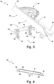
- the stop unit 50 in itself provides an embodiment and is in itself in FIG figure 3 shown.
- the fence assembly 50 may also be provided as part of a table saw.
- the figure 6 12 shows a corresponding table saw 20 which has a stop unit 50.
- the stop unit 50 comprises a stop arm 55, which extends in a longitudinal direction 54, for the purpose of abutting the workpiece 11.
- the stop arm 55 is aligned with its longitudinal direction in the y-direction, for example.
- the stop arm 55 includes a main portion 51 made of a first material that extends over more than half the length of the stop arm 55 .
- the feature "first material” mentioned here is a different feature than that referred to above in relation to FIG Saw blade cover 40 mentioned feature “first material”.
- the “first material” mentioned herein with respect to the anvil assembly 50 may also be referred to as “third material” or “main portion material” for purposes of distinction.
- the stop arm 55 also comprises at least one second end section 52 arranged at one end of the main section 51 in the longitudinal direction 54.
- the stop arm 55 comprises a second end section 52 at both ends located in the longitudinal direction, so that the stop arm has two end sections 52.
- the second end section 52 can come into contact with the saw blade 2 when a workpiece 11 is fed towards the saw blade 2 .
- the stop unit 50 in a state mounted on the support structure 12 of the table saw 20 can be moved into a position in which the end section 52 comes into contact with the saw blade 2, in particular the cutting area of the saw blade 2.
- the at least one end portion 52 is made of a second material that is different than the first material.
- the "second material” feature mentioned herein is a different feature than the “second material” feature mentioned above with respect to the saw blade cover 40 .
- the "second material” mentioned herein with respect to the stop assembly 50 may also be referred to as “fourth material” or “tail material” for the purpose of better distinction.
- the second material differs from the first material.
- the second material has a different conductivity than the first material.
- the first material is metal and/or the second material is plastic.
- the second material has a different, preferably lower, electrical conductivity than the human body.
- the table saw 20 is expediently designed to carry out the safety function, in particular for stopping the saw blade 2 and/or for moving the saw blade 2 into a safety position, on the basis of an electrical property, in particular an electrical conductivity, of an object in contact with the saw blade 2.
- the electrical property, in particular the electrical conductivity, of the second material is preferably such that the table saw 20 does not perform the safety function when the saw blade comes into contact with the end section 52 .
- the electrical property, in particular the electrical conductivity, of the first material is preferably such that the table saw 20 performs the safety function when the saw blade comes into contact with the first material.
- the stop arm 55 is expediently designed in the form of a strip and can also be referred to as a guide strip.
- the stop arm 55 is with its largest side in terms of area - its long side - normal to a horizontal direction, expediently orthogonal to the support surface 8 aligned.
- the main section 51 of the The stop arm 55 expediently extends over more than 70% of the length of the stop arm 55.
- the main section 51 is designed in the form of a strip and is aligned orthogonally to the bearing surface 8 with its largest side in terms of surface area.
- the longitudinal sides of the main section 51 are, for example, rectangular.
- the main section 51 is expediently made of an extruded profile and in particular made of metal.
- each end section 52 adjoins each of the two ends of the main section 51 .
- Each end section expediently occupies less than 20% of the length of the stop arm 55 .
- Each end section 52 expediently continues the transverse outer contour of the main section 51 in the longitudinal direction, so that the stop arm 55 results overall as a strip-shaped body with a constant thickness.
- Each end section 52 suitably has the same thickness as the main section 51 .
- the end face of each end section 52 located in the longitudinal direction of the stop arm 55 is expediently beveled.
- Each end section 52 is aligned normal to the bearing surface 8 with its largest side in terms of surface area—the long side. Due to the bevel on the respective end face, the longitudinal side of each end section 52 is triangular, for example.
- Each end section 52 is conveniently detachably attached to the main section 51 .
- each end section 51 is plugged into and/or onto an end face of the main section 52 .
- Each end section 52 is expediently designed as a plastic cap.
- Each end section 52 is expediently fastened to the main section 51 via a snap-in connection.
- each end section 51 has a Locking element 62 which engages in a corresponding locking opening of the main section 51.
- Each end section 52 can conveniently be detached from the main section 51 and replaced with a new end section 52 of identical design.
- each end section 52 is a wear part.
- a tool-free and/or non-destructive attachment and/or removal of each end section 52 from the main section 51 is possible.
- the stop arm 55 expediently also includes a covering layer 53 which is arranged on a longitudinal side of the stop arm 55 .
- the covering layer 53 is arranged in particular on that longitudinal side of the stop arm 55 on which the workpiece 11 rests when the stop unit 50 is used as intended.
- the covering layer 53 expediently covers the entire longitudinal side of the stop arm 55 .
- the cover layer 53 can expediently be made of a material that does not trigger the safety function mentioned above when it comes into contact with the saw blade 2 , ie in particular has a higher electrical conductivity than the human body and/or the main section 51 .
- the stop unit 55 also includes a bearing section 67 with which the stop unit 55 can be movably mounted on the support structure 12 of the table saw 20 .
- the bearing section 67 comprises a roller section 56 on which a plurality of rollers 57, 58 are arranged, via which the bearing section 67 can be movably mounted on the support structure 12.
- the roller section 56 comprises, for example, a horizontal section 64 extending in a horizontal direction, on which a plurality of, for example two, vertically extending vertical sections 65 are arranged.
- a plurality of rollers 57, 58 are arranged on each vertical section 65, for example two rollers per vertical section 65. Two of the rollers 57, 58 are expediently aligned in different spatial directions with respect to one another, in particular orthogonally to one another.
- each vertical section 65 comprises two rollers 57, 58 aligned in different spatial directions—example one horizontal roller 57 each whose roller plane is aligned parallel to a horizontal plane, and one vertical roller 58 each whose roller plane is aligned parallel to a vertical plane.
- the roller section 56 expediently also includes a sliding block 63.
- the sliding block 63 is in particular elongate and is expediently arranged on the underside of the horizontal section 64.
- the stop arm 55 is expediently mounted via a pivot bearing 60 such that it can pivot about a vertical pivot axis relative to the bearing section 67 .
- the pivot bearing 60 has an angle scale as an example.
- the stop arm 55 is also expediently supported in a linearly movable manner relative to the bearing section 67 via a linear bearing.
- the stop unit 50 has a connecting section 59 which, for example, is elongate and preferably extends in a horizontal direction, in particular in a direction orthogonal to the longitudinal direction of the horizontal section 64 .
- the stop arm 55 is expediently above the Pivot bearing 60 is pivotably mounted on the connecting section 59 and the connecting section 59 is linearly movable via the linear bearing, in particular in the longitudinal direction of the connecting section 59, on the bearing section 67.
- One or more operating elements are expediently present in order to lock and/or release the linear bearing, the pivot bearing 60 and/or the mounting of the bearing section 67 on the support structure.
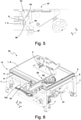
- the storage of the stop unit 55 on the support structure 12 is exemplary in the Figures 5 and 6 shown.
- the support structure 12 of the table saw 20 has one or more guide elements 6 on which the bearing section 67 is mounted or can be mounted.
- each guide element 6 is arranged on a respective peripheral wall 5 of the support structure 12 , in particular of the support section 1 .
- Each peripheral wall is oriented normal to a horizontal direction.
- Each guide element 6 is expediently designed as a rail element running in the horizontal direction.
- each guide element 6 provides a groove running in the horizontal direction, in particular a V-groove, into which the aforementioned sliding block 63 is inserted when mounting the bearing section 67 on the support structure 12 .
- Each guide element 6 is expediently offset downwards in the z-direction relative to the bearing surface 8 .
- Each guide element 6 provides a respective linear guide path for the bearing section 67 .
- the bearing portion 67 can be detached from one guide element 6 and attached to another guide element 6, for example to another peripheral wall 5.
- the stop unit 50 is mounted with its bearing section 67 on a peripheral wall 5 oriented normal to the y-direction.
- the stop unit 50 can be moved linearly in the x-direction along the guide element 6 located on this peripheral wall 5 .
- the stop arm 55 is located at least partially on or above the support surface 8 and can be positioned in its x-coordinate by the linear movement of the stop unit 50, in particular relative to the support section 1 and/or the saw blade 2.
- the stop unit 50 can be detached from the peripheral wall 5 oriented normal to the y-direction and attached to a peripheral wall 5 oriented normal to the x-direction. There, the stop unit 50 can then be moved in the y-direction in order to position the stop arm 55 in its y-coordinate.
- the figure 6 shows a detailed view of the mounting of the bearing section 67 on the peripheral wall 5 and the guide element 6 of the support structure 12.
- the bearing section 67 is in engagement with the guide element 6.
- the sliding block 63 is inserted into the groove provided by the guide element 6 .
- the vertical rollers 58 rest against the guide element 6 from below.
- the horizontal rollers 57 rest against the peripheral wall 5 .
- the guide arm (which can also be referred to as a guide bar) has protective caps attached to the ends which prevent a safety function from being triggered when sawing in, in particular an "active injury mitigation", AIM, function.
- AIM active injury mitigation
- the AIM feature can also be referred to as an active injury mitigation feature.
- a table saw 30 which provides another embodiment, will be explained.
- the table saw 30 is expediently designed like one of the table saws explained above.
- the table saw 30 includes the support structure 12 with the support section 1, which provides the support surface 8 for supporting the workpiece 11, and the saw blade 2, which engages through the opening of the support section 1, so that at least part of the saw blade 2 is below the support section Bottom 14 is located.
- the table saw 30 also includes a housing arrangement 80 located below the underside 14 of the support section, which surrounds the part of the saw blade 2 located below the underside 14 of the support section. The saw blade 2 can be pivoted together with the housing arrangement 80 relative to the support section 1 in order to set an angle between a cutting plane of the saw blade 2 and the support surface 8 .
- the table saw 30 includes a cover flap 87, which covers a gap between the housing arrangement 80 and the underside 14 of the support section that occurs when the housing arrangement 80 is pivoted, in order to prevent a user of the table saw 30 from escaping through the gap to the underside of the support section. Underside 14 located part of the saw blade 2 can access.
- the adjustment section 3 serves to pivot the saw blade 2 about a horizontal pivot axis, in particular a pivot axis running in the x-direction.
- the adjusting section 3 comprises a bearing section 81 arranged on the support structure 12, in particular the underside 14 of the support section, and a pivoting section 82, which is mounted pivotably relative to the bearing section 81 about the pivot axis mentioned.
- the pivot axis is defined, for example, by a guide section 94 present on the bearing section 81, in particular a guide slot, on which the pivot section 82 is guided.
- the figure 7 shows the pivoting portion 82 in a normal position in which the pivoting portion 82 is not is pivoted and is aligned orthogonally to the underside 14 of the support section.
- the figure 8 shows the pivoting section 82 in a pivoting position in which the pivoting section 82 is pivoted and is not aligned orthogonally to the underside 14 of the supporting section.
- the pivoting section 82 includes, for example, the housing arrangement 80, the saw blade 2 and expediently the drive unit 86.
- the drive unit 86 and the saw blade 2 are preferably mounted so as to be linearly movable relative to the housing arrangement 80 in order to set how far the saw blade 2 protrudes from the opening in the support surface 8 .
- the housing arrangement 80 includes, for example, a housing shell 83 whose largest side in terms of surface area, also referred to below as the lateral side 85, is aligned normal to the y-direction in the normal position.
- the housing shell 83 also includes an upper side 84 which is aligned orthogonally to the lateral side 85 and which is aligned parallel to the underside 14 of the supporting section when the pivoting section 82 is in the normal position.
- the housing shell 83 also includes a transverse side 93 oriented orthogonally to the lateral side 85 and orthogonally to the upper side 84, which is expediently oriented normal to the x-direction.
- the cover flap 87 is suitably made of a rigid material, preferably metal.
- the cover flap 87 is expediently designed as a cover plate.
- the cover flap 87 includes a plate-shaped cover portion 88.
- the cover flap 87 is elongate and aligned with its longitudinal direction in the x-direction.
- the cover flap 87 is mounted, for example, on the housing arrangement 80, in particular on the transverse side 93, and on the support structure, in particular on the underside 14 of the support section.
- the cover flap 87 includes a first fastening section 89, which is expediently designed as a lug, and is pivotably mounted on the housing shell 83, in particular the transverse side 93, via the first fastening section 89.
- the cover flap 87 also includes a second fastening section 91, with which the cover flap 87 is expediently mounted in a linearly movable manner on the support structure 12, in particular a guide slot 92.
- the second attachment section 91 is expediently an edge area of the cover flap 87.
- the guide slot 92 is expediently a gap between the support section underside 14 and another element of the support structure 12.
- the second attachment section 91 can also be firmly attached to the support structure 12.
- the cover flap 87 can be moved from a first position into a second position by pivoting the pivoting section 82, in particular the housing arrangement 80.
- the cover flap 87 is pivoted from the first position to the second position by pivoting the pivoting portion 82 from the normal position to the pivoted position.
- the cover flap 87 In the first position, the cover flap 87 is aligned parallel to the underside 14 of the support section.
- the cover flap 87 In the first position, the cover flap 87 is expediently at least partially between the upper side 84 and the underside 14 of the support section arranged.
- the cover flap 87 is aligned inclined about a horizontal axis, in particular the x-axis, in relation to the underside 14 of the support section.
- the cover flap 87 is expediently mounted on the housing arrangement 80 and the support structure 12 in such a way that the cover flap 87 is pivoted by pivoting the housing arrangement 80 in the opposite direction to the pivoting movement of the housing arrangement 80 .
- the support structure 12 expediently has a plurality of legs 7, via which the support section 1 can be supported relative to the ground. Between the legs 7 there are free areas through which a user can reach under the underside 14 of the support section.
- the housing arrangement 80 and the cover flap 87 consequently provide a cover device which covers the saw blade 2 in such a way that the user cannot touch the saw blade 2 under the table.
- the cover device can also be referred to as a lateral saw blade cover.
- the angle and height of the saw blade 2 can be adjusted.
- the side saw blade cover consists of several parts that conveniently cover the saw blade in all positions of the adjustable range and prevent a finger from penetrating the saw blade under the table.
- An accessory mounting structure 100 is also provided.
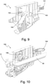
- the accessory mounting structure 100 is shown in FIG figure 9 unequipped and in the figure 10 shown with accessories.
- the accessory mounting structure 100 may be provided on its own or as part of a table saw, particularly one of the table saws 10, 20, 30 described above.
- the accessory attachment structure 100 is suitably attached to the deck portion underside 14 and extends vertically downward from the deck section underside 14 .
- the accessory attachment structure 100 is essentially plate-shaped and is aligned with its plate plane normal to a horizontal direction, for example normal to the y-direction.
- the accessory attachment structure 100 includes a plurality of interfaces to which attachments for the table saw can be attached, particularly attachments that are not currently in use.
- the accessory mounting structure 100 is specifically for storing the accessory items. In the fastened state, the accessory elements are expediently freely accessible from the outside and can preferably be removed from the accessory fastening structure 100 without the use of tools.
- the accessory attachment structure 100 has one, several or all of the following interfaces: a first interface 101, comprising in particular a latching hook, for fixing a push stick 105, a second interface 102, comprising in particular a latching hook for fixing the stop unit 50, a third interface 103, comprising in particular a latching hook, for fastening the riving knife 9, a fourth interface 104, comprising in particular a latching hook, for fastening a work center, for example a replacement cartridge, in particular for the safety function, and/or a fifth interface for fastening the saw blade cover.
- a first interface 101 comprising in particular a latching hook
- a second interface 102 comprising in particular a latching hook for fixing the stop unit 50
- a third interface 103 comprising in particular a latching hook, for fastening the riving knife 9
- a fourth interface 104 comprising in particular a latching hook, for fastening a work center, for example a replacement cartridge, in particular for the safety
- the accessory mounting structure 100 is preferably used to securely store the accessories on the table saw.
- the interfaces mentioned are on the accessory mounting structure for this purpose 100 integrated.
- the interfaces expediently have fixing elements.
- the accessory mounting structure 100 allows the user to easily remove the push stick 105 from the front face of the table saw oriented normal to the x-direction.
- the bag is attached to the table top with a screw and there is a side snap closure to reduce horizontal movement.
- a suction plate 130 is also provided.
- the suction plate 130 is in the figure 11 unequipped and in the figure 12 shown with accessories.
- the suction plate 130 can be provided on its own or as part of a table saw, in particular one of the table saws 10, 20, 30 described above.
- the suction plate 130 is expediently arranged below the underside 14 of the support section and at least partially surrounds the saw blade 2 .
- the suction plate 130 comprises a suction connection 131 to which a suction hose for sucking off dust generated during sawing can be attached.
- the suction plate 130 advantageously comprises a first interface 141 for a replacement saw blade 142 and other interfaces for attaching accessory elements 135, in particular tools for assembling and disassembling the saw blade 2, 142 and the expansion wedge and/or riving knife 9
- at least one accessory 135 forms part of the first interface 141.
- the function of the suction plate has been expanded to the effect that the suction plate also functions as a spare blade holder and is used to store the tools for assembling and disassembling the saw blade and the expansion wedge.
Landscapes
- Life Sciences & Earth Sciences (AREA)
- Engineering & Computer Science (AREA)
- Mechanical Engineering (AREA)
- Wood Science & Technology (AREA)
- Forests & Forestry (AREA)
- Sawing (AREA)
Abstract
Description
- Die Erfindung betrifft eine Tischsäge. Die vorliegende Erfindung befasst sich insbesondere mit der Aufgabe, die Wahrscheinlichkeit von Betriebsstörungen zu verringern und/oder die Betriebssicherheit zu erhöhen.
- Die Tischsäge umfasst eine Stützstruktur mit einem Auflageabschnitt, der eine Auflagefläche zur Auflage eines Werkstücks bereitstellt, sowie ein Sägeblatt, das durch eine Öffnung des Auflageabschnitts greift, so dass sich zumindest ein Teil des Sägeblatts unterhalb der Auflageabschnitt-Unterseite befindet. Die Tischsäge umfasst ferner eine unterhalb der Auflageabschnitt-Unterseite befindliche Gehäuseanordnung, die den unterhalb der Auflageabschnitt-Unterseite befindlichen Teil des Sägeblatts umgibt. Das Sägeblatt ist zusammen mit der Gehäuseanordnung relativ zum Auflageabschnitt verschwenkbar, um einen Winkel zwischen einer Schnittebene des Sägeblatts und der Auflagefläche einzustellen.
- Eine Aufgabe der Erfindung besteht darin, die Betriebssicherheit zu erhöhen.
- Die Aufgabe wird gelöst durch eine Tischsäge gemäß Anspruch 1. Die Tischsäge umfasst eine Abdeckklappe, die einen bei der Verschwenkung der Gehäuseanordnung entstehenden Spalt zwischen der Gehäuseanordnung und der Auflageabschnitt-Unterseite abdeckt, um so zu verhindern, dass ein Benutzer der Tischsäge durch den Spalt hin zum Sägeblatt greifen kann. Auf diese Weise kann die Betriebssicherheit der Tischsäge erhöht werden.
- Zweckmäßigerweise ist die Abdeckklappe an der Gehäuseanordnung und/oder der Stützstruktur gelagert, insbesondere beweglich. Vorzugsweise ist die Abdeckklappe an der Gehäuseanordnung beweglich gelagert und/oder an der Stützstruktur fest gelagert.
- Exemplarisch ist die Abdeckklappe durch Verschwenken der Gehäuseanordnung von einer ersten Stellung in eine zweite Stellung versetzbar. Die Abdeckklappe ist in der ersten Stellung parallel zur Auflageabschnitt-Unterseite ausgerichtet und/oder in der zweiten Stellung um eine horizontale Achse geneigt zur Auflageabschnitt-Unterseite ausgerichtet.
- Zweckmäßigerweise verfügt die Stützstruktur über mehrere Standbeine, über die der Auflageabschnitt gegenüber dem Boden abstützbar ist. Zwischen den Standbeinen sind jeweils freie Bereiche vorhanden, durch die ein Benutzer unter die Auflageabschnitt-Unterseite greifen kann. Die Tischsäge, insbesondere die Stützstruktur ist somit gewissermaßen unverkapselt und ermöglicht es einem Benutzer, in einfacher Weise unter den Auflageabschnitt zu greifen.
- Die Erfindung betrifft ferner eine Sägeblattabdeckung. Die Sägeblattabdeckung ist insbesondere als Sägeblatthaube ausgeführt und umfasst einen sich in einer Längsrichtung erstreckenden, aus einem ersten Material gefertigten Abdeckungskörper zum zumindest teilweisen Abdecken eines Sägeblatts der Tischsäge. Die Sägeblattabdeckung umfasst ferner einen stirnseitig an dem Abdeckungskörper angeordneten Kontaktbereich. Der Kontaktbereich ist relativ zur Längsrichtung angeschrägt, so dass durch Kontakt des Kontaktbereichs mit einem an das Sägeblatt herangeführten Werkstück eine Auslenkung des Abdeckungskörper bewirkbar ist.
- Eine Aufgabe der Erfindung besteht darin, die Sägeblattabdeckung so zu modifizieren, dass die Wahrscheinlichkeit von Betriebsstörungen verringert werden kann.
- Die Aufgabe wird gelöst durch eine Sägeblattabdeckung, bei der der Kontaktbereich einen aus einem zweiten Material gefertigten Gleitabschnitt aufweist, an dem das Werkstück beim Kontakt mit dem Kontaktbereich entlanggleiten kann.
- Insbesondere dann, wenn das Werkstück aus einem harten Material besteht und/oder an seiner dem Sägeblatt zuzuführenden Seite eine scharfe Kante aufweist, kann es bei konventionellen Sägeblattabdeckungen vorkommen, dass das Werkstück beim Kontakt mit dem Kontaktbereich in das Material des Kontaktbereichs einschneidet und folglich am Kontaktbereich hängenbleibt. Es kann dann dazu kommen, dass die Sägeblattabdeckung nicht ausgelenkt wird, so dass der Schnittbereich des Sägeblatts nicht freigegeben wird. Folglich kann das Werkstück nicht an den Schnittbereich des Sägeblatts herangeführt werden - es kommt zu einer Störung des Betriebs der Tischsäge.
- Durch die Ausstattung der Sägeblattabdeckung mit dem Gleitabschnitt kann die Wahrscheinlichkeit dieser Betriebsstörung zweckmäßigerweise verringert werden. Insbesondere kann durch den Gleitabschnitt verhindert werden, dass ein Werkstück beim Kontakt mit dem Kontaktbereich in diesen einschneidet und am Kontaktbereich hängenbleibt. Folglich kann die Wahrscheinlichkeit von Betriebsstörungen verringert werden.
- Das erste Material kann auch als Abdeckungskörper-Material bezeichnet werden und das zweite Material kann auch als Gleitabschnitt-Material bezeichnet werden. Das zweite Material unterscheidet sich von dem ersten Material. Zweckmäßigerweise weist das zweite Material eine größere Härte auf als das erste Material. Das erste Material ist insbesondere Kunststoff und/oder das zweite Material ist insbesondere Metall, vorzugsweise Aluminium.
- Der Gleitabschnitt ist zweckmäßigerweise streifenförmig. Vorzugsweise ist der Gleitabschnitt als Aluminiumband ausgeführt. Gemäß einer bevorzugten Ausgestaltung sind der Kontaktbereich und der Gleitabschnitt länglich. Zweckmäßigerweise verläuft der Gleitabschnitt in Längsrichtung des Kontaktbereichs.
- Der Kontaktbereich ist zweckmäßigerweise eine stirnseitige Kontaktfläche. Der Gleitabschnitt ist zweckmäßigerweise nur in einem Teilbereich, insbesondere einem in horizontaler Richtung zentralen Teilbereich, der stirnseitigen Kontaktfläche vorhanden.
- Gemäß einer alternativen Ausgestaltung ist der gesamte Kontaktbereich, insbesondere die gesamte Kontaktfläche aus dem zweiten Material gefertigt.
- Alternativ oder zusätzlich wird ferner eine Sägeblattabdeckung bereitgestellt, deren Abdeckungskörper insgesamt aus Metall, insbesondere Aluminium gefertigt ist.
- Die Erfindung betrifft ferner eine Tischsäge mit einer vorstehend beschriebenen Sägeblattabdeckung, einem Auflageabschnitt zum Auflegen des Werkstücks, sowie dem Sägeblatt.
- Gemäß einer bevorzugten Ausgestaltung deckt der Abdeckungskörper das Sägeblatt in einer Abdeckstellung zumindest teilweise ab. Der Abdeckungskörper ist relativ zum Sägeblatt bewegbar gelagert, so dass der Abdeckungskörper durch Beaufschlagung des Kontaktbereichs mit dem sich auf dem Auflageabschnitt in Richtung hin zu dem Sägeblatt bewegenden Werkstück in eine Freigabestellung versetzbar ist, in der das Sägeblatt weiter freigegeben wird als in der Abdeckstellung. Insbesondere wird in der Freigabestellung der Schnittbereich des Sägeblatts freigegeben. Als Schnittbereich soll derjenige Bereich des Sägeblatts bezeichnet werden, mit dem bei der bestimmungsgemäßen Verwendung der Tischsäge die Bearbeitung des Werkstücks erfolgt.
- Die Erfindung betrifft ferner eine Anschlagseinheit, insbesondere einen Winkelanschlag, zur Führung und/oder zum Vorschub eines Werkstücks zu einem Sägeblatt einer Tischsäge. Die Anschlagseinheit umfasst einen sich in einer Längsrichtung erstreckenden Anschlagsarm zur Anlage des Werkstücks. Der Anschlagsarm umfasst einen aus einem ersten Material gefertigten Hauptabschnitt, der sich über mehr als die Hälfte der Längserstreckung des Anschlagsarms erstreckt. Der Anschlagsarm umfasst ferner wenigstens einen an einem in Längsrichtung befindlichen Ende des Hauptabschnitts angeordneten zweiten Endabschnitt. Der zweite Endabschnitt kann beim Vorschub eines Werkstücks hin zu dem Sägeblatt in Kontakt mit dem Sägeblatt kommen.
- Eine Aufgabe der Erfindung besteht darin, die Anschlagseinheit so zu modifizieren, dass die Wahrscheinlichkeit von Betriebsstörungen reduziert werden kann.
- Die Aufgabe wird gelöst durch eine Anschlagseinheit, bei der der wenigstens eine Endabschnitt aus einem zweiten Material gefertigt ist.
- Bei dem Vorschub des Werkstücks mit der Anschlagseinheit kann es dazu kommen, dass der Endabschnitt mit dem Sägeblatt in Kontakt kommt. Konventionelle Anschlagseinheiten verfügen in der Regel über einen einstückigen Anschlagsarm aus Metall. Kommt das Sägeblatt mit einem metallischen Endabschnitt eines solchen konventionellen Anschlagsarm in Kontakt, so kann (sofern die Tischsäge über eine bestimmte Sicherheitsfunktion verfügt) es passieren, dass das Sägeblatt gestoppt und/oder in eine Sicherheitsstellung gefahren wird. Hierdurch wird der Betrieb der Tischsäge gestört. Ferner kann es zu einer Beschädigung des Anschlagsarm kommen, so dass aufgrund der einstückigen Ausführung der gesamte Anschlagsarm ausgetauscht werden muss.
- Dadurch, dass bei der vorliegenden Anschlagseinheit der Endabschnitt aus einem anderen Material gefertigt ist als der Hauptabschnitt, kann das Material des Endabschnitts (insbesondere unabhängig vom Material des Hauptabschnitts) so gewählt werden, dass eine möglicherweise bei der Tischsäge vorhandene Sicherheitsfunktion durch den Kontakt des Sägeblatts mit dem Endabschnitt nicht ausgelöst wird. Ferner kann das Material des Endabschnitts so gewählt werden, dass der Endabschnitt als günstiges Verschleißteil bereitgestellt werden kann. Gleichzeitig kann der Hauptabschnitt aus einem stabilen, beständigen Material, wie beispielsweise Metall, gefertigt werden, auch wenn dieses Material bei Kontakt des Sägeblatts mit dem Hauptabschnitt die Sicherheitsfunktion auslösen würde.
- Die in Bezug auf die Anschlagseinheit genannten Merkmale "erstes Material" und "zweites Material" sind andere Merkmale als die vorstehend in Bezug auf die Sägeblattabdeckung genannten Merkmale "erstes Material" und "zweites Material". Das in Bezug auf die Anschlagseinheit genannte Merkmal "erstes Material" kann auch als "drittes Material" oder als "Hauptabschnitt-Material" bezeichnet werden und das in Bezug auf die Anschlagseinheit genannte "zweite Material" kann auch als "viertes Material" oder als "Endabschnitt-Material" bezeichnet werden.
- Das in Bezug auf die Anschlagseinheit genannte zweite Material unterscheidet sich von dem in Bezug auf die Anschlagseinheit genannten ersten Material. Insbesondere weist das zweite Material eine andere Leitfähigkeit auf als das erste Material. Zweckmäßigerweise eine geringere Leitfähigkeit. Exemplarisch ist das erste Material Metall und/oder das zweite Material ist Kunststoff.
- Der wenigstens eine Endabschnitt ist zweckmäßigerweise abnehmbar an dem Hauptabschnitt angebracht. Exemplarisch ist der wenigstens eine Endabschnitt in und/oder auf eine Stirnseite des Hauptabschnitts gesteckt. Zweckmäßigerweise ist der Hauptabschnitt ein Strangpressprofil und/oder der Endabschnitt ist eine Kunststoffkappe.
- Die Erfindung betrifft ferner eine Tischsäge mit einer vorstehend beschriebenen Anschlagseinheit, einem Auflageabschnitt zum Auflegen des Werkstücks, sowie dem Sägeblatt. Die Tischsäge ist zweckmäßigerweise ausgebildet, auf Basis einer elektrischen Eigenschaft, insbesondere einer elektrischen Leitfähigkeit, eines mit dem Sägeblatt in Kontakt stehenden Objekts eine Sicherheitsfunktion, insbesondere zum Anhalten des Sägeblatts und/oder zum Versetzen des Sägeblatts in eine Sicherheitsstellung, auszuführen. Vorzugsweise ist die elektrische Eigenschaft, insbesondere die elektrische Leitfähigkeit des zweiten Materials derart, dass die Tischsäge bei Kontakt des Sägeblatts mit dem Endabschnitt die Sicherheitsfunktion nicht ausführt.
- Zweckmäßigerweise wird die Sicherheitsfunktion durch Kontakt des Sägeblatts mit dem Werkstück nicht ausgelöst und bei Kontakt des Sägeblatts mit dem menschlichen Körper ausgelöst.
- Die Erfindung betrifft ferner eine Tischsäge umfassend ein Sägeblatt und eine Stützstruktur mit einer Auflagefläche zum Auflegen des Werkstücks bei der Bearbeitung des Werkstücks mit dem Sägeblatt. Die Tischsäge umfasst eine Anschlagseinheit, insbesondere eine vorstehend erläuterte Anschlagseinheit, zur Führung und/oder zum Vorschub des Werkstücks zu dem Sägeblatt. Die Anschlagseinheit umfasst einen Lagerabschnitt, der mit einem Führungselement der Tischsäge in Eingriff steht, um so entlang des Führungselements eine bewegliche Lagerung der Anschlagseinheit relativ zur Stützstruktur bereitzustellen. Das Führungselement ist relativ zur Auflagefläche nach unten versetzt angeordnet.
- Gemäß einer bevorzugten Ausgestaltung umfasst der Lagerabschnitt Rollen, über die der Lagerabschnitt relativ zum Stützabschnitt beweglich gelagert ist. Zweckmäßigerweise sind zwei der Rollen in verschiedene Raumrichtungen zueinander ausgerichtet.
- Weitere exemplarische Merkmale und Ausführungsformen werden nachfolgend unter Bezugnahme auf die Figuren erläutert. Dabei zeigt
- Figur 1
- eine Sägeblattabdeckung,
- Figur 2
- eine Tischsäge mit der Sägeblattabdeckung,
- Figur 3
- eine Anschlagseinheit,
- Figur 4
- ein Anschlagsarm der Anschlagseinheit
- Figur 5
- einen Lagerabschnitt der Anschlagseinheit, der an einer Stützstruktur einer Tischsäge beweglich gelagert ist,
- Figur 6
- eine Tischsäge mit der Anschlagseinheit,
- Figur 7
- einen an einer Auflageabschnitt-Unterseite einer Tischsäge befindlichen Stellabschnitt in einer ersten Stellung,
- Figur 8
- den Stellabschnitt in einer zweiten Stellung,
- Figur 9
- eine unbestückte Zubehör-Befestigungsstruktur,
- Figur 10
- eine bestückte Zubehör-Befestigungsstruktur,
- Figur 11
- eine unbestückte Absaugplatte,
- Figur 12
- eine bestückte Absaugplatte.
- Bei der nachfolgenden Beschreibung wird auf die als x-Richtung, y-Richtung und z-Richtung bezeichneten, orthogonal zueinander ausgerichteten Raumrichtungen Bezug genommen. Die z-Richtung kann auch als Höhenrichtung bezeichnet werden und verläuft vertikal. Die x-Richtung und die y-Richtung sind Horizontalrichtungen.
- Zunächst soll auf den Grundaufbau der Tischsäge eingegangen werden. Die nachfolgende Erläuterung gilt zweckmäßigerweise für sämtliche hier erwähnte Tischsägen, insbesondere für die in den
Figuren 2 und6 gezeigten Tischsägen 10, 20, 30. Vorzugsweise handelt es sich bei sämtlichen hier erwähnten Tischsägen um dieselbe Tischsäge. - Die Tischsäge 10, 20, 30 ist exemplarisch als Tischkreissäge ausgeführt. Die Tischsäge 10, 20, 30 ist insbesondere ein halbstationäres Werkzeug. Die Tischsäge 10, 20, 30 umfasst ein Sägeblatt 2, insbesondere ein Kreissägeblatt. Zweckmäßigerweise umfasst die Tischsäge 10, 20, 30 eine Antriebseinheit 86 zum Antrieb, insbesondere Drehantrieb, des Sägeblatts 2. Die Antriebseinheit 86 umfasst zweckmäßigerweise einen Elektromotor.
- Die Tischsäge 10, 20, 30 umfasst eine Stützstruktur 12, die exemplarisch als Tisch ausgeführt ist. Die Stützstruktur 12 umfasst einen Auflageabschnitt 1, dessen Auflageabschnitt-Oberseite 8 als Auflagefläche 8 für ein mit dem Sägeblatt 2 zu bearbeitendes Werkstück 11 dient. Der Auflageabschnitt 1 ist exemplarisch plattenförmig ausgeführt, insbesondere als Tischplatte. Der Auflageabschnitt 1 weist zweckmäßigerweise eine rechteckige Grundfläche auf. Die Auflagefläche 8 ist zweckmäßigerweise rechteckig. Die Auflagefläche 8 ist normal zur z-Richtung ausgerichtet und vorzugsweise eben.
- Die Stützstruktur 12 umfasst ferner mehrere Standbeine 7 - exemplarisch vier an den vier Eckbereichen des Auflageabschnitts 1 angeordnete Standbeine 7 - über die der Auflageabschnitt 1 gegenüber dem Boden abgestützt ist. Zwischen den Standbeinen 7 sind zweckmäßigerweise freie Bereiche vorhanden, die sich exemplarisch über mehr als drei Viertel der vertikalen Erstreckung der Standbeine 7 erstrecken. Insbesondere ist zwischen zwei oder mehr Standbeinen 7 keine Verkleidung, insbesondere keine Gehäusewand, vorhanden. Ein Benutzer kann zwischen zwei Standbeine 7 hindurch in den unterhalb der Auflageabschnitt-Unterseite 14 vorhandenen freien Raum greifen.
- Im Auflageabschnitt 1, insbesondere der Auflagefläche 8 ist eine Öffnung, exemplarisch ein Schlitz, vorhanden, durch den das Sägeblatt 2 greift. Die Öffnung ist mit ihrer Längsrichtung in x-Richtung ausgerichtet. Ein Teil des Sägeblatts 2 befindet sich oberhalb des Auflageabschnitts 1, insbesondere oberhalb der Auflagefläche 8, und ein weiterer Teil des Sägeblatts befindet sich unterhalb des Auflageabschnitts 1, insbesondere unterhalb der Auflageabschnitt-Unterseite 14.
- Rein exemplarisch umfasst die Tischsäge 10, 20, 30 eine Sicherheitsfunktion, die bei einem detektierten Kontakt zwischen dem Sägeblatt 2 und einem Körperteil einer Person automatisch ausgelöst wird. Zweckmäßigerweise ist die Tischsäge 10, 20, 30 ausgebildet, über die Bereitstellung eines elektrischen Signals an das Sägeblatt 2 eine elektrische Eigenschaft, insbesondere eine elektrische Leitfähigkeit, eines mit dem Sägeblatt in Kontakt stehenden Objekts zu erfassen, um zu ermitteln, ob es sich bei dem Objekt um einen menschlichen Körperteil handelt. Die Tischsäge 10, 20, 30 ist ferner ausgebildet, auf Basis der erfassten elektrischen Leitfähigkeit die Sicherheitsfunktion auszuführen. Bei der Ausführung der Sicherheitsfunktion wird beispielsweise das Sägeblatt 2 angehalten, insbesondere abgebremst, und/oder das Sägeblatt 2 in eine Sicherheitsstellung versetzt, insbesondere in eine Sicherheitsstellung, bei der sich das Sägeblatt 2 vollständig unterhalb der Auflagefläche 8 befindet.
- Die Funktionsweise einer solchen Erfassung eines Kontakts des Sägeblatts 2 mit einem Körperteil und einer Sicherheitsfunktion ist z.B. aus der
EP 1 234 285 B1 bekannt, so dass an dieser Stelle auf eine detaillierte Beschreibung der Funktionsweise verzichtet wird. - Die Tischsäge 10, 20, 30 verfügt exemplarisch über einen Stellabschnitt 3, der exemplarisch in den
Figuren 7 und 8 gezeigt ist. Der Stellabschnitt 3 ist ausgebildet, die Stellung des Sägeblatts 2 relativ zur Auflagefläche 8 einzustellen. Zweckmäßigerweise ist der Stellabschnitt 3 ausgebildet, das Sägeblatt 2 relativ zur Auflagefläche 8 um eine in x-Richtung verlaufende Schwenkachse zu verschwenken, um einen Winkel zwischen der Schnittebene des Sägeblatts 2 und der Auflagefläche 8 einzustellen. Zweckmäßigerweise ist der Stellabschnitt 3 ferner ausgebildet, das Sägeblatt 2 in verschiedene Stellungen entlang eines linearen Bewegungswegs, insbesondere eines vertikalen und/oder um die vorstehend genannte Schwenkachse verschwenkbaren linearen Bewegungswegs, zu versetzen, um einzustellen, wie weit das Sägeblatt 2 aus der Öffnung nach oben ragt. Auf diese Weise kann beispielsweise die Schnitttiefe der Tischsäge 10, 20, 30 eingestellt werden. - Im Folgenden soll im Detail auf die Sägeblattabdeckung 40 eingegangen werden. Die Sägeblattabdeckung 40 kann als Teil einer der hier beschriebenen Tischsägen 10, 20, 30 und/oder für sich genommen bereitgestellt sein. Zweckmäßigerweise stellt die Sägeblattabdeckung 40 bereits für sich genommen eine Ausführungsform dar.
- Die Sägeblattabdeckung 40 ist für sich genommen in der
Figur 1 gezeigt. In denFiguren 2 und6 ist die Sägeblattabdeckung 40 in einem an der Tischsäge 10, 20, 30 befestigten Zustand bezeigt. - Die Sägeblattabdeckung 40 ist insbesondere als Sägeblatthaube ausgeführt und umfasst einen sich in einer Längsrichtung (der Sägeblattabdeckung 40) erstreckenden, aus einem ersten Material gefertigten Abdeckungskörper 41 zum zumindest teilweisen Abdecken des Sägeblatts 2 der Tischsäge 10, 20, 30. Die Sägeblattabdeckung 40 umfasst ferner einen stirnseitig an dem Abdeckungskörper 41 angeordneten Kontaktbereich 47. Der Kontaktbereich 47 ist relativ zur Längsrichtung der Sägeblattabdeckung 40 angeschrägt, so dass durch Kontakt des Kontaktbereichs 47 mit einem sich hin zu dem Sägeblatt 2 bewegenden Werkstück 11 eine Auslenkung des Abdeckungskörper 41 bewirkbar ist. Der Kontaktbereich 47 weist einen aus einem zweiten Material gefertigten Gleitabschnitt 48 auf, an dem das Werkstück 11 beim Kontakt mit dem Kontaktbereich 47 entlanggleiten kann.
- Der Gleitabschnitt 48 ist dafür vorgesehen, zu verhindern, dass das Werkstück 11 beim Kontakt mit dem Kontaktbereich 47 in diesen einschneidet und am Kontaktbereich 47 hängenbleibt.
- Das zweite Material unterscheidet sich von dem ersten Material. Zweckmäßigerweise weist das zweite Material eine größere Härte auf als das erste Material. Das erste Material ist insbesondere Kunststoff und/oder das zweite Material ist insbesondere Metall, vorzugsweise Aluminium.
- Die Sägeblattabdeckung 40, insbesondere der Abdeckungskörper 41, ist vorzugsweise länglich und insbesondere flach und/oder plattenförmig ausgeführt. Exemplarisch ist der Abdeckungskörper 41 schwertförmig ausgeführt. In bestimmungsgemäßer Ausrichtung sind die flächenmäßig größten Seiten des Abdeckungskörpers 41 - insbesondere die Längsseiten - normal zu einer Horizontalrichtung, insbesondere normal zur y-Richtung, ausgerichtet, wie dies in den
Figuren 2 und6 gezeigt ist. - An der Unterseite des Abdeckungskörpers 41 ist eine Öffnung 43, insbesondere ein Schlitz, vorhanden, in die das Sägeblatt 2 zumindest teilweise aufgenommen werden kann. Das Sägeblatt 2 wird in dem Zustand, in dem es sich zumindest teilweise in der Öffnung 43 befindet, exemplarisch von den Längsseiten, der Oberseite und/oder der vorderen Stirnseite des Abdeckungskörpers 41 abgedeckt.
- Die Sägeblattabdeckung 40 umfasst einen Anschlussabschnitt 44, der exemplarisch über einen Sauganschluss 45 verfügt. An den Sauganschluss 45 kann ein (in den Figuren nicht gezeigter) Saugschlauch angeschlossen werden, um Staubpartikel abzusaugen, die beim Sägen des Werkstücks 11 entstehen. Der Anschlussabschnitt 44 umfasst eine mechanische Schnittstelle zur Befestigung der Sägeblattabdeckung 40 an einem Befestigungsabschnitt 46 der Tischsäge 10, 20, 30, insbesondere an dem Spaltkeil 9. Der Spaltkeil 9 ist exemplarisch in x-Richtung hinter dem Sägeblatt 2 angeordnet. Der Spaltkeil 9 ragt exemplarisch aus der Öffnung der Auflagefläche 8 heraus. Zweckmäßigerweise ist der Abdeckungskörper 41 um eine horizontale Achse, insbesondere eine in y-Richtung verlaufende Achse, verschwenkbar am Anschlussabschnitt 44 gelagert. Der Anschlussabschnitt 44 ist in Längsrichtung der Sägeblattabdeckung 40 an der hinteren Stirnseite der Sägeblattabdeckung 40 angeordnet. In dem an dem Befestigungsabschnitt 46 befestigten Zustand, also bei bestimmungsgemäßer Installation der Sägeblattabdeckung 40 an der Tischsäge 10, 20, 30, ist die Sägeblattabdeckung 40 zweckmäßigerweise mit ihrer Längsrichtung parallel zur x-Richtung ausgerichtet.
- Der vorstehend bereits erwähnte Kontaktbereich 47 ist in Längsrichtung der Sägeblattabdeckung 40 an der vorderen Stirnseite der Sägeblattabdeckung 40 angeordnet. Zweckmäßigerweise stellt der Kontaktbereich 47 die vordere Stirnseite der Sägeblattabdeckung 40, insbesondere die vordere Stirnseite des Abdeckungskörpers 41, dar.
- Der Kontaktbereich 47 ist gegenüber der Längsrichtung der Sägeblattabdeckung 40 angeschrägt. Wie in den
Figuren 2 und6 zu sehen, ist der Kontaktbereich 47 (im installierten Zustand der Sägeblattabdeckung 40) gegenüber der x-Richtung und gegenüber der Auflagefläche 8 angeschrägt, also geneigt ausgerichtet. Insbesondere ist der Kontaktbereich 47 normal zu einer x-z-Richtung ausgerichtet. In einem x-z-Schnitt verläuft der Kontaktbereich 47 von unten ausgehend schräg nach oben rechts, in Richtung weg von dem Sägeblatt 2. - Der Abdeckungskörper 41 weist zweckmäßigerweise eine Kontaktstelle 53 auf, die im installierten Zustand der Sägeblattabdeckung 40 vorzugsweise den tiefsten Punkt der Sägeblattabdeckung 40 bildet und/oder auf der Auflagefläche 8 aufliegt (sofern der Abdeckungskörper 41 nicht durch Beaufschlagung mit der Werkstück 11 ausgelenkt, insbesondere angehoben, ist).
- Der Kontaktbereich 47 ist in einem x-z-Schnitt zweckmäßigerweise gekrümmt, insbesondere parabelförmig. Der Kontaktbereich 47 ist derart angeschrägt, dass beim Auftreffen eines auf der Auflagefläche befindlichen Werkstücks 11, das sich in x-Richtung in Richtung hin zu dem Sägeblatt 2 bewegt, auf den Kontaktbereich 47, eine Kraftkomponente (insbesondere eine Kraftkomponente nach oben) bereitgestellt wird, die eine Auslenkung, insbesondere eine Verschwenkung, des Abdeckungskörpers 41 relativ zum Sägeblatt 2, der Auflagefläche 8 und/oder dem Anschlussabschnitt 44 bewirkt, insbesondere eine Auslenkung und/oder Verschwenkung nach oben.
- Indem das Werkstück 11 vom Benutzer gegen den Kontaktbereich 47 gedrückt wird, kann der Abdeckungskörper 41 in seiner Stellung verändert werden, so dass der Abdeckungskörper 41 den Weg zu dem Sägeblatt 2 und/oder den Schnittbereich des Sägeblatts 2 freigibt. Zweckmäßigerweise hebt der Abdeckungskörper 41 dabei mit seiner Kontaktstelle 53 von der Auflagefläche 8 ab.
- Während der Bewegung des Werkstücks 11 hin zu dem Sägeblatt 2 bleibt das Werkstück 11 für einen Teil des Wegs in Kontakt mit dem Kontaktbereich 47 und gleitet dabei entlang des Gleitabschnitts 48. Der Abdeckungskörper 41 wird dabei durch den Kontakt des Werkstücks 11 mit dem Kontaktbereich 47 immer weiter nach oben gedrückt.
- Vor dem Kontakt des Werkstücks 11 mit dem Kontaktbereichs 47 befindet sich der Abdeckungskörper 41 zweckmäßigerweise in einer Abdeckstellung, in der der Abdeckungskörper 41 das Sägeblatt 2 zumindest teilweise abdeckt und die Kontaktstelle 53 zweckmäßigerweise auf der Auflagefläche 8 aufliegt. Wird der Kontaktbereich 47 mit dem sich in Richtung hin zu dem Sägeblatt 2 bewegenden Werkstück 11 beaufschlagt, so wird der Abdeckungskörper 41 immer weiter ausgelenkt, bis er sich in einer Freigabestellung befindet, in der das Sägeblatt 2 weiter freigegeben wird als in der Abdeckstellung. Zweckmäßigerweise wird in der Freigabestellung der Abdeckungskörper 41 so weit ausgelenkt, dass das Werkstück 11 dem Schnittbereich Sägeblatt 2 zugeführt werden kann und durch das Sägeblatt 2 bearbeitet werden kann.
- Der Gleitabschnitt 48 ist zweckmäßigerweise streifenförmig, insbesondere bandförmig, ausgeführt. Vorzugsweise ist der Gleitabschnitt 48 als Metallband, insbesondere als Aluminiumband, ausgeführt. Alternativ kann der Gleitabschnitt 48 auch aus einem anderen Hartmaterial gefertigt sein, das zweckmäßigerweise härter als das erste Material des Abdeckungskörpers 41 ist. Der Gleitabschnitt 48, insbesondere das Aluminiumband, ist in den Kontaktbereich 47, insbesondere die Kontaktfläche, eingelassen und/oder auf diesen aufgesetzt, insbesondere aufgeklebt.
- Vorzugsweise sind der Kontaktbereich 47 und der Gleitabschnitt 48 länglich ausgeführt. Zweckmäßigerweise verläuft der Gleitabschnitt 48 in Längsrichtung des Kontaktbereichs 47. Die Längsrichtung des Kontaktbereichs 47 und/oder des Gleitabschnitts 48 verläuft zweckmäßigerweise relativ zur Auflagefläche 8 diagonal nach oben, insbesondere in Richtung weg von dem Sägeblatt 2. Der Kontaktbereich 47 ist zweckmäßigerweise eine stirnseitige Kontaktfläche, insbesondere des Abdeckungskörpers 11.
- Der Gleitabschnitt 48 ist zweckmäßigerweise nur in einem Teilbereich, insbesondere einem in horizontaler Richtung, insbesondere in y-Richtung, zentralen Teilbereich, der stirnseitigen Kontaktfläche vorhanden. In y-Richtung ergeben sich zweckmäßigerweise seitlich vom Gleitabschnitt 48 Flächenabschnitte 49, an denen der Gleitabschnitt 48 nicht vorhanden ist. Diese Flächenabschnitte 49 sind zweckmäßigerweise aus dem ersten Material gefertigt und nehmen exemplarisch mehr als die Hälfte der y-Erstreckung der Kontaktfläche ein, so dass der Gleitabschnitt 48 zweckmäßigerweise weniger als die Hälfte der y-Erstreckung einnimmt.
- Gemäß einer alternativen Ausgestaltung ist der gesamte Kontaktbereich, insbesondere die gesamte Kontaktfläche aus dem zweiten Material gefertigt, so dass der gesamte Kontaktbereich den Gleitabschnitt darstellt.
- Der Gleitabschnitt 48 erstreckt sich zweckmäßigerweise über mehr als die Hälfte der Längserstreckung des Kontaktbereichs 47. Exemplarisch verfügt der Abdeckungskörper 41 über einen nach schräg nach oben abragenden Vorsprung 52, der im Bereich der vorderen Stirnseite des Abdeckungskörpers 41 angeordnet ist, und einen Teil des Kontaktbereichs 47 bereitstellt. Der Gleitabschnitt 48 erstreckt sich zweckmäßigerweise in den durch den Vorsprung 52 bereitgestellten Teil des Kontaktbereichs 47.
- Der Gleitabschnitt 48 kann auch als Verstärkung der Stirnfläche der Sägeblattabdeckung bezeichnet werden. Die Sägeblattabdeckung kann auch als Schutzeinrichtung bezeichnet werden. Der Gleitabschnitt 48 ist zweckmäßigerweise ein Streifen aus einem Hartstoff, der an der Schutzeinrichtung befestigt ist, so dass die Stirnfläche - insbesondere der Kontaktbereich 47 - der Schutzeinrichtung mit dem Streifen an einer Berührkante eines geschnittenen Materials eines zu bearbeitenden Werkstücks gleiten kann. Der Gleitabschnitt 48
- exemplarisch der Hartstoffstreifen - schützt die Stirnfläche der Schutzeinrichtung vor Einklemmen (Engraben/Einkerben) an der scharfen Berührkante des geschnittenen Materials, die beim Führen des geschnittenen Materials in den Schnitt über den Hartstoffstreifen gleitet.
- Alternativ oder zusätzlich wird als Ausführungsform ferner eine Sägeblattabdeckung bereitgestellt, deren Abdeckungskörper insgesamt aus Metall, insbesondere Aluminium gefertigt ist. Diese Sägeblattabdeckung ist zweckmäßigerweise wie vorstehend erläutert ausgeführt, bis auf den Aspekt, dass der Gleitabschnitt nicht aus einem zweiten Material sondern aus demselben Material wie der restliche Abdeckungskörper gefertigt ist.
- Die Erfindung betrifft ferner eine Anschlagseinheit 50, insbesondere einen Winkelanschlag, zur Führung und/oder Vorschub eines Werkstücks 11 zu einem Sägeblatt 2 einer Tischsäge.
- Die Anschlagseinheit 50 stellt für sich genommen eine Ausführungsform bereit und ist für sich genommen in der
Figur 3 gezeigt. Die Anschlagseinheit 50 kann auch als Teil einer Tischsäge bereitgestellt sein. DieFigur 6 zeigt eine entsprechende Tischsäge 20, die eine Anschlagseinheit 50 aufweist. - Die Anschlagseinheit 50 umfasst einen sich in einer Längsrichtung 54 erstreckenden Anschlagsarm 55 zur Anlage des Werkstücks 11. In der
Figur 6 ist der Anschlagsarm 55 mit seiner Längsrichtung exemplarisch in y-Richtung ausgerichtet. - Der Anschlagsarm 55 umfasst einen aus einem ersten Material gefertigten Hauptabschnitt 51, der sich über mehr als die Hälfte der Längserstreckung des Anschlagsarms 55 erstreckt. Das hier erwähnte Merkmal "erstes Material" ist ein anderes Merkmal als das vorstehend in Bezug auf die Sägeblattabdeckung 40 erwähnte Merkmal "erstes Material". Das hier in Bezug auf die Anschlagseinheit 50 erwähnte "erste Material" kann zum Zwecke der besseren Unterscheidung auch als "drittes Material" oder als "Hauptabschnitt-Material" bezeichnet werden.
- Der Anschlagsarm 55 umfasst ferner wenigstens einen an einem in Längsrichtung 54 befindlichen Ende des Hauptabschnitts 51 angeordneten zweiten Endabschnitt 52. Exemplarisch umfasst der Anschlagsarm 55 an beiden in Längsrichtung befindlichen Enden jeweils einen zweiten Endabschnitt 52, so dass der Anschlagsarm zwei Endabschnitte 52 aufweist.
- Der zweite Endabschnitt 52 kann beim Vorschub eines Werkstücks 11 hin zu dem Sägeblatt 2 in Kontakt mit dem Sägeblatt 2 kommen. Insbesondere kann die Anschlagseinheit 50 in einem an der Stützstruktur 12 der Tischsäge 20 gelagerten Zustand in eine Stellung versetzt werden, in der der Endabschnitt 52 mit dem Sägeblatt 2, insbesondere dem Schnittbereich des Sägeblatts 2, in Kontakt kommt. Der wenigstens eine Endabschnitt 52 ist aus einem zweiten Material gefertigt, das sich von dem ersten Material unterscheidet.
- Das hier erwähnte Merkmal "zweites Material" ist ein anderes Merkmal als das vorstehend in Bezug auf die Sägeblattabdeckung 40 erwähnte Merkmal "zweites Material". Das hier in Bezug auf die Anschlagseinheit 50 erwähnte "zweite Material" kann zum Zwecke der besseren Unterscheidung auch als "viertes Material" oder als "Endabschnitt-Material" bezeichnet werden.
- Das zweite Material unterscheidet sich von dem ersten Material. Insbesondere weist das zweite Material eine andere Leitfähigkeit auf als das erste Material. Zweckmäßigerweise eine geringere Leitfähigkeit. Exemplarisch ist das erste Material Metall und/oder das zweite Material ist Kunststoff. Das zweite Material weist insbesondere eine andere, vorzugsweise eine geringere, elektrische Leitfähigkeit auf als der menschliche Körper.
- Durch die Bereitstellung des Endabschnitts 52 aus dem zweiten Material kann verhindert werden, dass bei Kontakt des Endabschnitt 52 mit dem Sägeblatt 2 die vorstehend erwähnte Sicherheitsfunktion der Tischsäge 20 ausgelöst wird (sofern sie vorhanden ist). Die Tischsäge 20 ist zweckmäßigerweise ausgebildet, auf Basis einer elektrischen Eigenschaft, insbesondere einer elektrischen Leitfähigkeit, eines mit dem Sägeblatt 2 in Kontakt stehenden Objekts die Sicherheitsfunktion, insbesondere zum Anhalten des Sägeblatts 2 und/oder zum Versetzen des Sägeblatts 2 in eine Sicherheitsstellung, auszuführen. Vorzugsweise ist die elektrische Eigenschaft, insbesondere die elektrische Leitfähigkeit des zweiten Materials derart, dass die Tischsäge 20 bei Kontakt des Sägeblatts mit dem Endabschnitt 52 die Sicherheitsfunktion nicht ausführt.
- Vorzugsweise ist die elektrische Eigenschaft, insbesondere die elektrische Leitfähigkeit des ersten Materials derart, dass die Tischsäge 20 bei Kontakt des Sägeblatts mit dem ersten Material die Sicherheitsfunktion ausführt.
- Der Anschlagsarm 55 ist zweckmäßigerweise leistenförmig ausgeführt und kann auch als Führungsleiste bezeichnet werden. Der Anschlagsarm 55 ist mit seiner flächenmäßig größten Seite - seiner Längsseite - normal zu einer horizontalen Richtung, zweckmäßigerweise orthogonal zur Auflagefläche 8, ausgerichtet. Der Hauptabschnitt 51 des Anschlagsarm 55 erstreckt sich zweckmäßigerweise über mehr als 70 % der Längserstreckung des Anschlagsarms 55. Der Hauptabschnitt 51 ist leistenförmig ausgeführt und mit seiner flächenmäßig größten Seite orthogonal zur Auflagefläche 8 ausgerichtet. Die Längsseiten des Hauptabschnitts 51 ist exemplarisch rechteckig. Der Hauptabschnitt 51 ist zweckmäßigerweise ein Strangpressprofil und insbesondere aus Metall gefertigt.
- In Längsrichtung schließt sich an beiden Enden des Hauptabschnitts 51 jeweils ein Endabschnitt 52 an. Jeder Endabschnitt nimmt zweckmäßigerweise weniger als 20 % der Längserstreckung des Anschlagsarms 55 ein. Jeder Endabschnitt 52 führt in Längsrichtung zweckmäßigerweise die querseitige Außenkontur des Hauptabschnitts 51 fort, so dass sich der Anschlagsarm 55 insgesamt als leistenförmiger Körper mit konstanter Dicke ergibt. Jeder Endabschnitt 52 weist zweckmäßigerweise die gleiche Dicke wie der Hauptabschnitt 51 auf. Zweckmäßigerweise ist die in Längsrichtung des Anschlagsarms 55 befindliche Stirnseite jedes Endabschnitts 52 abgeschrägt. Jeder Endabschnitt 52 ist mit seiner flächenmäßig größten Seite - der Längsseite - normal zur Auflagefläche 8 ausgerichtet. Durch die Abschrägung an der jeweiligen Stirnseite ist die Längsseite jedes Endabschnitts 52 exemplarisch dreiecksförmig.
- Jeder Endabschnitt 52 ist zweckmäßigerweise abnehmbar an dem Hauptabschnitt 51 angebracht. Exemplarisch ist jeder Endabschnitt 51 in und/oder auf eine Stirnseite des Hauptabschnitts 52 gesteckt. Zweckmäßigerweise ist jeder Endabschnitt 52 als Kunststoffkappe ausgeführt. Jeder Endabschnitt 52 ist zweckmäßigerweise über eine Rastverbindung an dem Hauptabschnitt 51 befestigt. Exemplarisch verfügt jeder Endabschnitt 51 über ein Rastelement 62, das in eine entsprechende Rastöffnung des Hauptabschnitts 51 greift.
- Jeder Endabschnitt 52 kann zweckmäßigerweise von dem Hauptabschnitt 51 abgenommen und durch einen neuen, identisch ausgeführten Endabschnitt 52 ersetzt werden.
- Zweckmäßigerweise handelt es sich bei jedem Endabschnitt 52 um ein Verschleißteil. Insbesondere ist eine werkzeuglose und/oder zerstörungsfreie Anbringung und/oder Abnahme jedes Endabschnitts 52 von dem Hauptabschnitt 51 möglich.
- Der Anschlagsarm 55 umfasst zweckmäßigerweise ferner eine Abdeckschicht 53, die an einer Längsseite des Anschlagsarms 55 angeordnet ist. Die Abdeckschicht 53 ist insbesondere an derjenigen Längsseite des Anschlagsarms 55 angeordnet, an der im bestimmungsgemäßen Gebrauch der Anschlagseinheit 50 das Werkstück 11 anliegt. Zweckmäßigerweise deckt die Abdeckschicht 53 die gesamte Längsseite des Anschlagsarms 55 ab. Die Abdeckschicht 53 kann zweckmäßigerweise aus einem Material gefertigt sein, das bei Kontakt mit dem Sägeblatt 2 die vorstehend erwähnte Sicherheitsfunktion nicht auslöst, also insbesondere eine höhere elektrische Leitfähigkeit als der menschliche Körper und/oder der Hauptabschnitt 51 aufweist.
- Die Anschlagseinheit 55 umfasst ferner einen Lagerabschnitt 67 mit dem die Anschlagseinheit 55 an der Stützstruktur 12 der Tischsäge 20 beweglich gelagert werden kann. Der Lagerabschnitt 67 umfasst einen Rollenabschnitt 56, an dem mehrere Rollen 57, 58 angeordnet sind, über die der Lagerabschnitt 67 beweglich an der Stützstruktur 12 gelagert werden kann.
- Der Rollenabschnitt 56 umfasst exemplarisch einen sich in einer horizontalen Richtung erstreckenden Horizontalabschnitt 64, an dem mehrere, exemplarisch zwei, sich vertikal erstreckende Vertikalabschnitte 65 angeordnet sind.
- An jedem Vertikalabschnitt 65 sind mehrere Rollen 57, 58 angeordnet, exemplarisch zwei Rollen pro Vertikalabschnitt 65. Zweckmäßigerweise sind zwei der Rollen 57, 58 in verschiedene Raumrichtungen zueinander ausgerichtet, insbesondere orthogonal zueinander. Exemplarisch umfasst jeder Vertikalabschnitt 65 zwei in verschiedene Raumrichtungen ausgerichtete Rollen 57, 58 - exemplarisch jeweils eine Horizontalrolle 57, deren Rollenebene parallel zu einer Horizontalebene ausgerichtet ist, und jeweils eine Vertikalrolle 58, deren Rollenebene parallel zu einer Vertikalebene ausgerichtet ist.
- Der Rollenabschnitt 56 umfasst zweckmäßigerweise ferner einen Nutenstein 63. Der Nutenstein 63 ist insbesondere länglich ausgeführt und zweckmäßigerweise an der Unterseite des Horizontalabschnitts 64 angeordnet.
- Der Anschlagsarm 55 ist zweckmäßigerweise über ein Schwenklager 60 um eine vertikale Schwenkachse relativ zum Lagerabschnitt 67 verschwenkbar gelagert. Das Schwenklager 60 weist exemplarisch eine Winkelskala auf. Der Anschlagsarm 55 ist ferner zweckmäßigerweise über ein Linearlager relativ zum Lagerabschnitt 67 linearbeweglich gelagert. Exemplarisch verfügt die Anschlagseinheit 50 über einen Verbindungsabschnitt 59, der exemplarisch länglich ist und sich vorzugsweise in eine horizontale Richtung, insbesondere in eine zur Längsrichtung des Horizontalabschnitts 64 orthogonal ausgerichtete Richtung, erstreckt. Zweckmäßigerweise ist der Anschlagsarm 55 über das Schwenklager 60 verschwenkbar an dem Verbindungsabschnitt 59 gelagert und der Verbindungsabschnitt 59 ist über das Linearlager linearbeweglich, insbesondere in Längsrichtung des Verbindungsabschnitts 59, an dem Lagerabschnitt 67 gelagert. Zweckmäßigerweise sind ein oder mehrere Bedienelemente vorhanden, um das Linearlager, das Schwenklager 60 und/oder die Lagerung des Lagerabschnitts 67 an der Stützstruktur zu sperren und/oder freizugeben.
- Die Lagerung der Anschlagseinheit 55 an der Stützstruktur 12 ist exemplarisch in den
Figuren 5 und 6 gezeigt. - Insbesondere weist die Stützstruktur 12 der Tischsäge 20 ein oder mehrere Führungselemente 6 auf, an denen der Lagerabschnitt 67 gelagert ist oder gelagert werden kann. Exemplarisch ist jedes Führungselement 6 an einer jeweiligen Umfangswand 5 der Stützstruktur 12, insbesondere des Auflageabschnitts 1, angeordnet. Jede Umfangswand ist normal zu einer Horizontalrichtung ausgerichtet. Jedes Führungselement 6 ist zweckmäßigerweise als in horizontaler Richtung verlaufendes Schienenelement ausgeführt. Exemplarisch stellt jedes Führungselement 6 eine in Horizontalrichtung verlaufende Nut, insbesondere eine V-Nut, bereit, in die der vorstehend erwähnte Nutenstein 63 bei der Lagerung des Lagerabschnitts 67 an der Stützstruktur 12 eingesetzt ist.
- Jedes Führungselement 6 ist zweckmäßigerweise relativ zur Auflagefläche 8 in z-Richtung nach unten versetzt angeordnet. Jedes Führungselement 6 stellt einen jeweiligen linearen Führungsweg für den Lagerabschnitt 67 bereit. Der Lagerabschnitt 67 kann von einem Führungselement 6 abgenommen werden und an ein anderes Führungselement 6, beispielsweise an einer anderen Umfangswand 5, angebracht werden.
- In der
Figur 6 ist die Anschlagseinheit 50 mit ihrem Lagerabschnitt 67 exemplarisch an einer normal zur y-Richtung ausgerichteten Umfangswand 5 gelagert. Die Anschlagseinheit 50 kann in x-Richtung linearbeweglich entlang des an dieser Umfangswand 5 befindlichen Führungselements 6 bewegt werden. Der Anschlagsarm 55 befindet sich dabei zumindest teilweise auf oder über der Auflagefläche 8 und kann durch die Linearbewegung der Anschlagseinheit 50 in seiner x-Koordinate positioniert werden, insbesondere relativ zum Auflageabschnitt 1 und/oder dem Sägeblatt 2. - Die Anschlagseinheit 50 kann von der normal zur y-Richtung ausgerichteten Umfangswand 5 abgenommen werden und an einer normal zur x-Richtung ausgerichteten Umfangswand 5 angebracht werden. Dort kann die Anschlagseinheit 50 dann in y-Richtung bewegt werden, um den Anschlagsarm 55 in seiner y-Koordinate zu positionieren.
- Die
Figur 6 zeigt eine Detailansicht der Lagerung des Lagerabschnitts 67 an der Umfangswand 5 und dem Führungselement 6 der Stützstruktur 12. Der Lagerabschnitt 67 steht mit dem Führungselement 6 in Eingriff. Exemplarisch ist der Nutenstein 63 in die von dem Führungselement 6 bereitgestellte Nut eingesetzt. Die Vertikalrollen 58 liegen von unten an dem Führungselement 6 an. Die Horizontalrollen 57 liegen an der Umfangswand 5 an. - Die Führung der Anschlagseinheit 50 erfolgt also in einer V-Nut, die nicht (wie konventionell üblich) in der Tischplatte
- exemplarisch der Auflagefläche 8 - angeordnet ist, sondern stattdessen an der Umfangswand 5 angeordnet ist. Ferner erfolgt die Führung mittels Rollen an der V-Nut. Zusätzlich gibt es zweckmäßigerweise seitliche Rollen - die horizontalen Rollen - welche einem Verkippen entgegenwirken. Die Rollen sind drehbar an dem Lagerabschnitt, der auch als Winkelanschlagsrahmen bezeichnet werden kann, gelagert. Am Rahmen des Winkelanschlags ist der Führungsarm angebracht (exemplarisch über den Verbindungsabschnitt), der auf dem Auflageabschnitt liegt, der auch als Sägetisch bezeichnet werden kann. Der Führungsarm führt das zu bearbeitende Werkstück. Der Führungsarm ist vorzugsweise in Bezug auf die Schnittebene in einem beliebigen Winkel im Bereich von +/-90° einstellbar. Unter diesem Winkel ist es möglich, ihn am Winkelanschlagsrahmen zu befestigen und unter diesem Winkel das Material in den Schnittbereich des Sägeblatts zu führen und/oder schieben. Der Drehwinkel des Führungsarms kann an der Winkelskala abgelesen werden, die Teil des Winkelanschlags ist.
- Der Führungsarm (der auch als Führungsleiste bezeichnet werden kann) besitzt an den Enden aufgesteckte Schutzkappen welche beim Einsägen ein Auslösen einer Sicherheitsfunktion, insbesondere einer "Active-Injury-Mitigation", AIM, -Funktion verhindern. Die AIM-Funktion kann auch als aktive Verletzungsminderungsfunktion bezeichnet werden.
- Nachstehend soll unter Bezugnahme auf die
Figuren 2 ,7 und 8 eine Tischsäge 30 erläutert werden, die eine weitere Ausführungsform bereitstellt. Die Tischsäge 30 ist zweckmäßigerweise wie eine der vorstehend erläuterten Tischsägen ausgebildet. - Die Tischsäge 30 umfasst die Stützstruktur 12 mit dem Auflageabschnitt 1, der die Auflagefläche 8 zur Auflage des Werkstücks 11 bereitstellt, sowie das Sägeblatt 2, das durch die Öffnung des Auflageabschnitts 1 greift, so dass sich zumindest ein Teil des Sägeblatts 2 unterhalb der Auflageabschnitt-Unterseite 14 befindet. Die Tischsäge 30 umfasst ferner eine unterhalb der Auflageabschnitt-Unterseite 14 befindliche Gehäuseanordnung 80, die den unterhalb der Auflageabschnitt-Unterseite 14 befindlichen Teil des Sägeblatts 2 umgibt. Das Sägeblatt 2 ist zusammen mit der Gehäuseanordnung 80 relativ zum Auflageabschnitt 1 verschwenkbar, um einen Winkel zwischen einer Schnittebene des Sägeblatts 2 und der Auflagefläche 8 einzustellen.
- Die Tischsäge 30 umfasst eine Abdeckklappe 87, die einen bei der Verschwenkung der Gehäuseanordnung 80 entstehenden Spalt zwischen der Gehäuseanordnung 80 und der Auflageabschnitt-Unterseite 14 abdeckt, um so zu verhindern, dass ein Benutzer der Tischsäge 30 durch den Spalt hin zum unterhalb der Auflageabschnitt-Unterseite 14 befindlichen Teil des Sägeblatts 2 greifen kann.
- In den
Figuren 7 und 8 ist ein Abschnitt der Auflageabschnitt-Unterseite 14 und eines daran befindlichen Stellabschnitts 3 gezeigt. Wie vorstehend bereits erläutert, dient der Stellabschnitt 3 dazu, das Sägeblatt 2 um eine horizontale Schwenkachse, insbesondere eine in x-Richtung verlaufende Schwenkachse, zu verschwenken. Der Stellabschnitt 3 umfasst einen an der Stützstruktur 12, insbesondere der Auflageabschnitt-Unterseite 14, angeordneten Lagerabschnitt 81 und einen Schwenkabschnitt 82, der relativ zum Lagerabschnitt 81 um die genannte Schwenkachse verschwenkbar gelagert ist. Die Schwenkachse wird exemplarisch durch einen an dem Lagerabschnitt 81 vorhandenen Führungsabschnitt 94, insbesondere einen Führungsschlitz, definiert, an dem der Schwenkabschnitt 82 geführt ist. - Die
Figur 7 zeigt den Schwenkabschnitt 82 in einer Normalstellung, in der der Schwenkabschnitt 82 nicht verschwenkt ist und orthogonal zur Auflageabschnitt-Unterseite 14 ausgerichtet ist. - Die
Figur 8 zeigt den Schwenkabschnitt 82 in einer Schwenkstellung, in der der Schwenkabschnitt 82 verschwenkt ist und nicht orthogonal zur Auflageabschnitt-Unterseite 14 ausgerichtet ist. - Der Schwenkabschnitt 82 umfasst exemplarisch die Gehäuseanordnung 80, das Sägeblatt 2 und zweckmäßigerweise die Antriebseinheit 86. Die Antriebseinheit 86 und das Sägeblatt 2 sind vorzugsweise relativ zur Gehäuseanordnung 80 linearbeweglich gelagert, um einzustellen, wie weit das Sägeblatt 2 aus der Öffnung in der Auflagefläche 8 herausragt.
- Die Gehäuseanordnung 80 umfasst exemplarisch eine Gehäuseschale 83, deren flächenmäßig größte Seite, nachstehend auch als seitliche Seite 85 bezeichnet, in Normalstellung normal zur y-Richtung ausgerichtet ist. Die Gehäuseschale 83 umfasst ferner eine orthogonal zur seitlichen Seite 85 ausgerichtete Oberseite 84, die in der Normalstellung des Schwenkabschnitts 82 parallel zur Auflageabschnitt-Unterseite 14 ausgerichtet ist. Die Gehäuseschale 83 umfasst ferner eine orthogonal zur seitlichen Seite 85 und orthogonal zur Oberseite 84 ausgerichtete Querseite 93, die zweckmäßigerweise normal zur x-Richtung ausgerichtet ist.
- Die Abdeckklappe 87 ist zweckmäßigerweise aus einem starren Material gefertigt, vorzugsweise Metall. Zweckmäßigerweise ist die Abdeckklappe 87 als Abdeckblech ausgeführt. Die Abdeckklappe 87 umfasst einen plattenförmigen Abdeckabschnitt 88. Die Abdeckklappe 87 ist länglich ausgeführt und mit ihrer Längsrichtung in x-Richtung ausgerichtet.
- Die Abdeckklappe 87 ist exemplarisch an der Gehäuseanordnung 80, insbesondere an der Querseite 93, und an der Stützstruktur, insbesondere an der Auflageabschnitt-Unterseite 14 gelagert. Exemplarisch umfasst die Abdeckklappe 87 einen ersten Befestigungsabschnitt 89, der zweckmäßigerweise als Lasche ausgebildet ist, und ist über den ersten Befestigungsabschnitt 89 verschwenkbar an der Gehäuseschale 83, insbesondere der Querseite 93, gelagert. Die Abdeckklappe 87 umfasst ferner einen zweiten Befestigungsabschnitt 91, mit dem die Abdeckklappe 87 zweckmäßigerweise linearbeweglich an der Stützstruktur 12, insbesondere einem Führungsschlitz 92, gelagert ist. Der zweite Befestigungsabschnitt 91 ist zweckmäßigerweise ein Randbereich der Abdeckklappe 87. Der Führungsschlitz 92 ist zweckmäßigerweise ein Zwischenraum zwischen der Auflageabschnitt-Unterseite 14 und einem weiteren Element der Stützstruktur 12. Alternativ kann der zweite Befestigungsabschnitt 91 auch fest an der Stützstruktur 12 befestigt sein.
- Exemplarisch ist die Abdeckklappe 87 durch Verschwenken des Schwenkabschnitts 82, insbesondere der Gehäuseanordnung 80, von einer ersten Stellung in eine zweite Stellung versetzbar. Insbesondere wird die Abdeckklappe 87 dadurch von der ersten Stellung in die zweite Stellung verschwenkt, dass der Schwenkabschnitt 82 von der Normalstellung in die Schwenkstellung verschwenkt wird. Die Abdeckklappe 87 ist in der ersten Stellung parallel zur Auflageabschnitt-Unterseite 14 ausgerichtet. Zweckmäßigerweise ist die Abdeckklappe 87 in der ersten Stellung zumindest teilweise zwischen der Oberseite 84 und der Auflageabschnitt-Unterseite 14 angeordnet. In der zweiten Stellung ist die Abdeckklappe 87 um eine horizontale Achse, insbesondere die x-Achse, geneigt zur Auflageabschnitt-Unterseite 14 ausgerichtet.
- Zweckmäßigerweise ist die Abdecklappe 87 derart an der Gehäuseanordnung 80 und der Stützstruktur 12 gelagert, dass die Abdeckklappe 87 durch Verschwenkung der Gehäuseanordnung 80 gegensinnig zur Verschwenkbewegung der Gehäuseanordnung 80 verschwenkt wird.
- Zweckmäßigerweise verfügt die Stützstruktur 12 über mehrere Standbeine 7, über die der Auflageabschnitt 1 gegenüber dem Boden abstützbar ist. Zwischen den Standbeinen 7 sind jeweils freie Bereiche vorhanden, durch die ein Benutzer unter die Auflageabschnitt-Unterseite 14 greifen kann.
- Mit der Gehäuseanordnung 80 und der Abdeckklappe 87 wird folglich eine Abdeckeinrichtung bereitgestellt, die das Sägeblatt 2 so abdeckt, dass der Benutzer das Sägeblatt 2 unter dem Tisch nicht berühren kann. Die Abdeckeinrichtung kann auch als seitliche Sägeblattabdeckung bezeichnet werden. Das Sägeblatt 2 ist winkel- und höhen-verstellbar. Die seitliche Sägeblattabdeckung besteht aus mehreren Teilen, die das Sägeblatt zweckmäßigerweise in allen Positionen des einstellbaren Bereichs abdecken und das Eindringen eines Fingers zu dem Sägeblatt unter dem Tisch verhindern.
- Ferner wird eine Zubehör-Befestigungsstruktur 100 bereitgestellt. Die Zubehör-Befestigungsstruktur 100 ist in der
Figur 9 unbestückt und in derFigur 10 mit Zubehör bestückt gezeigt. Die Zubehör-Befestigungsstruktur 100 kann für sich genommen oder als Teil einer Tischsäge, insbesondere einer der vorstehend beschriebenen Tischsägen 10, 20, 30 bereitgestellt sein. - Die Zubehör-Befestigungsstruktur 100 ist zweckmäßigerweise an der Auflageabschnitt-Unterseite 14 befestigt und erstreckt sich von der Auflageabschnitt-Unterseite 14 vertikal nach unten. Die Zubehör-Befestigungsstruktur 100 ist im Wesentlichen plattenförmig ausgeführt und mit ihrer Plattenebene normal zu einer Horizontalrichtung, exemplarisch normal zur y-Richtung ausgerichtet. Die Zubehör-Befestigungsstruktur 100 umfasst eine Mehrzahl an Schnittstellen, an denen Zubehörelemente für die Tischsäge befestigt werden können, insbesondere Zubehörelemente, die aktuell nicht in Gebrauch sind. Die Zubehör-Befestigungsstruktur 100 dient insbesondere zur Aufbewahrung der Zubehörelemente. Die Zubehörelemente sind im befestigten Zustand zweckmäßigerweise von außen frei zugänglich und vorzugsweise werkzeuglos von der Zubehör-Befestigungsstruktur 100 abnehmbar.
- Exemplarisch weist die Zubehör-Befestigungsstruktur 100 eine, mehrere oder sämtliche der folgenden Schnittstellen auf: eine erste Schnittstelle 101, umfassend insbesondere einen Rasthaken, zur Befestigung eines Schiebestocks 105, eine zweite Schnittstelle 102, umfassend insbesondere einen Rasthaken, zum Befestigen der Anschlagseinheit 50, eine dritte Schnittstelle 103, umfassend insbesondere einen Rasthaken, zum Befestigen des Spaltkeils 9, eine vierte Schnittstelle 104, umfassend insbesondere einen Rasthaken, zum Befestigen eines Workcenters, beispielsweise einer Ersatzpatrone, insbesondere für die Sicherheitsfunktion, und/oder eine fünfte Schnittstelle zur Befestigung der Sägeblattabdeckung.
- Die Zubehör-Befestigungsstruktur 100 dient vorzugsweise zur sicheren Aufbewahrung der Zubehörelemente an der Tischsäge. Hierzu sind die genannten Schnittstellen an der Zubehör-Befestigungsstruktur 100 ingegriert. Die Schnittstellen weisen zweckmäßigerweise Fixierungselemente auf. Vorzugsweise ermöglicht die Zubehör-Befestigungsstruktur 100 dem Benutzer ein einfaches Entnehmen des Schiebestocks 105 von der normal zur x-Richtung ausgerichteten Frontseite der Tischsäge.
- Die Tasche wird mittels Schraube an der Tischplatte befestigung und um die horizontale Bewegung zu reduzieren ist ein seitlicher Schnappverschluss vorhanden.
- Ferner wird eine Absaugplatte 130 bereitgestellt. Die Absaugplatte 130 ist in der
Figur 11 unbestückt und in derFigur 12 mit Zubehör bestückt gezeigt. Die Absaugplatte 130 kann für sich genommen oder als Teil einer Tischsäge, insbesondere einer der vorstehend beschriebenen Tischsägen 10, 20, 30 bereitgestellt sein. Zweckmäßigerweise ist die Absaugplatte 130 unterhalb der Auflageabschnitt-Unterseite 14 angeordnet und umgibt das Sägeblatt 2 zumindest teilweise. Die Absaugplatte 130 umfasst einen Sauganschluss 131, an dem ein Saugschlauch zum Absaugen von beim Sägen erzeugtem Staub befestigt werden kann. - In vorteilhafter Weise umfasst die Absaugplatte 130 auf ihrer dem Sägeblatt 2 abgewandten Seite eine erste Schnittstelle 141 für ein Ersatzsägeblatt 142 sowie weitere Schnittstellen zur Befestigung von Zubehörelementen 135, insbesondere Werkzeugen zum Montieren und Demontieren des Sägeblatts 2, 142 und des Dehnkeils und/oder Spaltkeils 9. Vorzugsweise stellt wenigstens ein Zubehörelement 135 einen Teil der ersten Schnittstelle 141 dar.
- Bei der vorliegenden Absaugplatte, die auch als Absaughaube bezeichnet werden kann, ist die Funktion der Absaugplatte dahingehend erweitert, dass die Absaugplatte ferner als Ersatzblatthalters dient und zur Aufbewahrung der Werkzeuge zum Montieren und Demontieren des Sägeblattes und des Dehnkeils dient.
Claims (11)
- Tischsäge (30), umfassend eine Stützstruktur (12) mit einem Auflageabschnitt (1), der eine Auflagefläche (8) zur Auflage eines Werkstücks (11) bereitstellt, sowie ein Sägeblatt (2), das durch eine Öffnung des Auflageabschnitts (1) greift, so dass sich zumindest ein Teil des Sägeblatts (2) unterhalb der Auflageabschnitt-Unterseite (14) befindet, ferner umfassend eine unterhalb der Auflageabschnitt-Unterseite (14) befindliche Gehäuseanordnung (80), die den unterhalb der Auflageabschnitt-Unterseite (14) befindlichen Teil des Sägeblatts (2) umgibt, wobei das Sägeblatt (2) zusammen mit der Gehäuseanordnung (80) relativ zum Auflageabschnitt (1) verschwenkbar ist, um einen Winkel zwischen einer Schnittebene des Sägeblatts (2) und der Auflagefläche (8) einzustellen, wobei die Tischsäge ferner eine Abdeckklappe (87) umfasst, die einen bei der Verschwenkung der Gehäuseanordnung (80) entstehenden Spalt zwischen der Gehäuseanordnung (80) und der Auflageabschnitt-Unterseite (14) abdeckt, um so zu verhindern, dass ein Benutzer der Tischsäge durch den Spalt hin zum Sägeblatt greifen kann, wobei die Abdeckklappe (87) durch Verschwenken der Gehäuseanordnung (80) von einer ersten Stellung in eine zweite Stellung versetzbar ist, wobei die Abdeckklappe (87) in der ersten Stellung im Wesentlichen parallel zur Auflagefläche (8) ausgerichtet ist und/oder in der zweiten Stellung um eine horizontale Achse geneigt zur Auflagefläche (8) ausgerichtet ist, wobei die Tischsäge (30) ferner einen Stellabschnitt (3) umfasst, der dazu dient, das Sägeblatt (2) um eine horizontale Schwenkachse zu verschwenken, wobei der Stellabschnitt (3) einen an der Stützstruktur (12) angeordneten Lagerabschnitt (81) und einen Schwenkabschnitt (82) umfasst, der relativ zum Lagerabschnitt (81) um die horizontale Schwenkachse verschwenkbar gelagert ist und die Gehäuseanordnung (80) und das Sägeblatt (2) umfasst, wobei die Abdeckklappe (87) dadurch von der ersten Stellung in die zweite Stellung verschwenkbar ist, dass der Schwenkabschnitt (82) von einer Normalstellung in eine Schwenkstellung verschwenkt wird, wobei der Schwenkabschnitt (82) in der Normalstellung orthogonal zur Auflageabschnitt-Unterseite (14) ausgerichtet ist und/oder in der Schwenkstellung nichtorthogonal zur Auflageabschnitt-Unterseite (14) ausgerichtet ist.
- Tischsäge (30) nach Anspruch 1, wobei die Abdeckklappe (87) an der Gehäuseanordnung (80) und/oder der Stützstruktur (12) beweglich gelagert ist.
- Tischsäge (30) nach einem der voranstehenden Ansprüche, wobei die Stützstruktur (12) über mehrere Standbeine (7) verfügt, über die der Auflageabschnitt (1) gegenüber einem Boden abstützbar ist, und zwischen den Standbeinen (7) jeweils freie Bereiche vorhanden sind, durch die ein Benutzer unter die Auflageabschnitt-Unterseite (14) greifen kann.
- Tischsäge (30) nach einem der voranstehenden Ansprüche, wobei die Abdecklappe (87) derart an der Gehäuseanordnung (80) und der Stützstruktur (12) gelagert ist, dass die Abdeckklappe (87) durch Verschwenkung der Gehäuseanordnung (80) gegensinnig zur Verschwenkbewegung der Gehäuseanordnung (80) verschwenkt wird.
- Tischsäge (30) nach einem der voranstehenden Ansprüche, wobei die Abdeckklappe (87) aus einem starren Material gefertigt ist, vorzugsweise Metall, und/oder als Abdeckblech ausgeführt ist.
- Tischsäge (30) nach einem voranstehenden Anspruch, wobei die Gehäuseanordnung (80) eine Gehäuseschale (83) umfasst, die eine Oberseite (84) aufweist, die in der Normalstellung des Schwenkabschnitts (82) parallel zur Auflageabschnitt-Unterseite 14 ausgerichtet ist.
- Tischsäge (30) nach Anspruch 6, wobei die Abdeckklappe (87) in der ersten Stellung zumindest teilweise zwischen der Oberseite (84) und der Auflageabschnitt-Unterseite (14) angeordnet ist.
- Tischsäge (30) nach einem voranstehenden Anspruch, wobei die Abdeckklappe (87) einen ersten Befestigungsabschnitt (89) umfasst, der zweckmäßigerweise als Lasche ausgebildet ist, und über den ersten Befestigungsabschnitt (89) verschwenkbar an einer/der Gehäuseschale 83 der Gehäuseanordnung 80 gelagert ist.
- Tischsäge (30) nach einem voranstehenden Anspruch, wobei die Abdeckklappe (87) einen zweiten Befestigungsabschnitt (91) umfasst, mit dem die Abdeckklappe (87) zweckmäßigerweise linearbeweglich an der Stützstruktur (12), insbesondere einem Führungsschlitz 92, gelagert ist.
- Tischsäge (30) nach Anspruch 9, wobei der zweite Befestigungsabschnitt (91) ein Randbereich der Abdeckklappe (87) ist.
- Tischsäge (30) nach Anspruch 9 oder 10, wobei der Führungsschlitz (92) ein Zwischenraum zwischen der Auflageabschnitt-Unterseite (14) und einem weiteren Element der Stützstruktur (12) ist.
Applications Claiming Priority (3)
| Application Number | Priority Date | Filing Date | Title |
|---|---|---|---|
| DE102019200366.4A DE102019200366A1 (de) | 2019-01-14 | 2019-01-14 | Sägeblattabdeckung, Anschlagseinheit und Tischsäge |
| PCT/EP2020/050384 WO2020148149A1 (de) | 2019-01-14 | 2020-01-09 | Tischsäge |
| EP20700774.1A EP3820658B1 (de) | 2019-01-14 | 2020-01-09 | Tischsäge |
Related Parent Applications (3)
| Application Number | Title | Priority Date | Filing Date |
|---|---|---|---|
| EP20700774.1A Division-Into EP3820658B1 (de) | 2019-01-14 | 2020-01-09 | Tischsäge |
| EP20700774.1A Division EP3820658B1 (de) | 2019-01-14 | 2020-01-09 | Tischsäge |
| PCT/EP2020/050384 Previously-Filed-Application WO2020148149A1 (de) | 2019-01-14 | 2020-01-09 | Tischsäge |
Publications (2)
| Publication Number | Publication Date |
|---|---|
| EP3960405A1 true EP3960405A1 (de) | 2022-03-02 |
| EP3960405B1 EP3960405B1 (de) | 2023-10-25 |
Family
ID=69157854
Family Applications (4)
| Application Number | Title | Priority Date | Filing Date |
|---|---|---|---|
| EP21199058.5A Active EP3960405B1 (de) | 2019-01-14 | 2020-01-09 | Tischsäge |
| EP20700773.3A Active EP3880418B1 (de) | 2019-01-14 | 2020-01-09 | Tischsäge mit einer anschlagseinheit |
| EP20700462.3A Pending EP3911484A1 (de) | 2019-01-14 | 2020-01-09 | Sägeblattabdeckung und tischsäge |
| EP20700774.1A Active EP3820658B1 (de) | 2019-01-14 | 2020-01-09 | Tischsäge |
Family Applications After (3)
| Application Number | Title | Priority Date | Filing Date |
|---|---|---|---|
| EP20700773.3A Active EP3880418B1 (de) | 2019-01-14 | 2020-01-09 | Tischsäge mit einer anschlagseinheit |
| EP20700462.3A Pending EP3911484A1 (de) | 2019-01-14 | 2020-01-09 | Sägeblattabdeckung und tischsäge |
| EP20700774.1A Active EP3820658B1 (de) | 2019-01-14 | 2020-01-09 | Tischsäge |
Country Status (8)
| Country | Link |
|---|---|
| US (3) | US12064896B2 (de) |
| EP (4) | EP3960405B1 (de) |
| JP (3) | JP7230214B2 (de) |
| CN (3) | CN113646146B (de) |
| DE (1) | DE102019200366A1 (de) |
| DK (1) | DK3960405T3 (de) |
| FI (1) | FI3960405T3 (de) |
| WO (3) | WO2020148149A1 (de) |
Families Citing this family (5)
| Publication number | Priority date | Publication date | Assignee | Title |
|---|---|---|---|---|
| DE202021100243U1 (de) * | 2021-01-19 | 2022-04-20 | Altendorf Gmbh | Formatkreissäge mit Sicherheitseinrichtung zur Vermeidung von Schnittverletzungen |
| USD1018614S1 (en) | 2021-08-05 | 2024-03-19 | Benjamin K. Watson | Saw guard |
| US11691311B2 (en) | 2021-08-05 | 2023-07-04 | Benjamin K. Watson | Saw guard and methods of use thereof |
| DE102022201167A1 (de) * | 2022-02-03 | 2023-08-03 | Festool Gmbh | Sägevorrichtung und Verfahren |
| TWI883946B (zh) * | 2024-05-06 | 2025-05-11 | 仕興機械工業股份有限公司 | 帶鋸機的集塵結構 |
Citations (2)
| Publication number | Priority date | Publication date | Assignee | Title |
|---|---|---|---|---|
| US20170252841A1 (en) * | 2016-03-05 | 2017-09-07 | Zhiming Wang | Dustless Table Saw |
| EP3424656A1 (de) * | 2017-05-22 | 2019-01-09 | Festool GmbH | Schutzabdeckung für eine säge und damit ausgestattete säge |
Family Cites Families (92)
| Publication number | Priority date | Publication date | Assignee | Title |
|---|---|---|---|---|
| US3128801A (en) * | 1964-04-14 | Brede | ||
| US2603252A (en) | 1952-07-15 | petersen | ||
| US1397606A (en) * | 1918-07-29 | 1921-11-22 | Christian N Smith | Safety-shield for circular saws |
| US1888679A (en) * | 1931-01-07 | 1932-11-22 | Walt Products Corp De | Safety device for cutting machines |
| US2980152A (en) * | 1957-09-25 | 1961-04-18 | Slavin Edwin | Undertable mounting for portable power tool |
| US2968325A (en) | 1957-12-31 | 1961-01-17 | Theodore S Wandvik | Table saw gauge frame |
| GB887003A (en) * | 1958-11-10 | 1962-01-10 | Horstmann & Sherwen Ltd | Improvements in or relating to circular sawing machines |
| US3060979A (en) * | 1961-04-19 | 1962-10-30 | Daniel J Hanvin | Machine bench employing a portable, manually-operable electric power tool |
| US3222970A (en) | 1963-04-12 | 1965-12-14 | Morgan Construction Co | Link mounted saw assembly |
| FR1376578A (fr) | 1963-08-03 | 1964-10-31 | Protecteur avec garde-main pour scie circulaire à table | |
| US3285303A (en) * | 1964-09-25 | 1966-11-15 | Rudolph J Kwiatkowski | Miter table and saw |
| DE1803537A1 (de) * | 1968-10-17 | 1970-06-11 | Lutz Dr Ing Hans | Schutzhaube fuer Holzkreissaegen |
| JPS4981290U (de) | 1972-10-31 | 1974-07-13 | ||
| US3955457A (en) * | 1974-03-25 | 1976-05-11 | Kenneth Mendelson | Table mounting for power tool |
| US3905263A (en) | 1974-08-09 | 1975-09-16 | Roger W Smith | Table mounting for portable power saw |
| DE2910095C2 (de) | 1979-03-15 | 1983-12-01 | Eugen Lutz GmbH u. Co Maschinenfabrik, 7130 Mühlacker | Schiebetisch für Tischkreissägen |
| JPS5657723U (de) | 1979-10-03 | 1981-05-18 | ||
| US4502518A (en) | 1982-05-20 | 1985-03-05 | George Lewin | Work table for saws and other tools |
| US4483573A (en) | 1982-07-09 | 1984-11-20 | Keller David L | Tool adapter for working table top storage cabinet |
| US5038486A (en) | 1989-08-04 | 1991-08-13 | The J.D.S. Company, Inc. | Miter gauge |
| US5042346A (en) * | 1989-12-11 | 1991-08-27 | Shopsmith, Inc. | Apparatus for fabricating accurate mitered corners |
| JPH0767681B2 (ja) * | 1991-06-27 | 1995-07-26 | 松下電工株式会社 | 電動丸鋸 |
| US5379669A (en) | 1993-08-23 | 1995-01-10 | Roedig; Joseph L. | Precision miter gauge |
| US5743161A (en) * | 1995-07-31 | 1998-04-28 | Boudreau; Jon P. | Angularly adjustable table saw jig |
| DE19529705C2 (de) | 1995-08-12 | 1997-08-28 | Metabowerke Kg | Wälzlagereinrichtung, insbesondere für eine Holzbearbeitungsmaschine |
| US5894776A (en) | 1996-01-17 | 1999-04-20 | Bartz; William R. | Table saw top and mitre bar |
| US5797307A (en) | 1996-12-10 | 1998-08-25 | Horton; Edward H. | Portable combination table, cross-cut, rip-cut, and miter saw |
| DE29718913U1 (de) | 1997-10-24 | 1999-02-18 | Scintilla Ag, Solothurn | Tisch zur Aufnahme einer Werkzeugmaschine |
| FR2773096B3 (fr) | 1997-12-26 | 2000-04-07 | Andre Dieu | Ensemble de guidage de piece a usiner comportant des moyens de reglage angulaires precis |
| US6095024A (en) * | 1998-06-03 | 2000-08-01 | Vermont American Corporation | Miter fence-box joint fixture |
| US5970835A (en) | 1998-09-10 | 1999-10-26 | Black & Decker Inc. | Throat plate for a tool |
| US6796208B1 (en) * | 1999-02-19 | 2004-09-28 | Matthew Roy Jorgensen | Sawdust collection hood for table saw |
| US8079295B2 (en) | 2008-06-20 | 2011-12-20 | Sd3, Llc | Table saw blade guards and blade guard assemblies including lateral blade guards, and table saws including the same |
| US8646369B2 (en) * | 2007-10-01 | 2014-02-11 | Sd3, Llc | Table saw guards, splitter assemblies, accessories, and table saws including the same |
| US6994004B2 (en) | 2000-09-29 | 2006-02-07 | Sd3, Llc | Table saw with improved safety system |
| US7827890B2 (en) | 2004-01-29 | 2010-11-09 | Sd3, Llc | Table saws with safety systems and systems to mount and index attachments |
| EP1234285B1 (de) | 1999-10-01 | 2016-06-15 | Sd3, Llc | Tischsäge mit Schutzsystem |
| US7284467B2 (en) | 2000-08-14 | 2007-10-23 | Sd3, Llc | Apparatus and method for detecting dangerous conditions in power equipment |
| US6237457B1 (en) | 2000-02-02 | 2001-05-29 | Taylor Design Group, Inc. | Apparatus for precisely guiding a workpiece relative to a work surface |
| US6293177B1 (en) * | 2000-04-20 | 2001-09-25 | Mackenzie George L. | Workpiece positioning device |
| US6755107B2 (en) | 2001-05-18 | 2004-06-29 | One World Technologies Lmt. | Miter saw having a light beam alignment system |
| US6499224B1 (en) | 2001-08-07 | 2002-12-31 | Albert Asick | Method and device for reproducibly and accurately positioning a work piece on a power tool |
| US6481477B1 (en) | 2002-01-03 | 2002-11-19 | Credo Tool Company | Fence assembly for a router table |
| US20040003696A1 (en) | 2002-06-13 | 2004-01-08 | Radda Richard Ray | Sliding miter fence |
| TW554813U (en) | 2002-09-26 | 2003-09-21 | P & F Brother Ind Corp | Lifting structure for eye shielding cover of cutting machine |
| US6736044B2 (en) * | 2002-10-07 | 2004-05-18 | Chin-Chin Chang | Table saw having a blade suspension structure |
| US8286539B2 (en) | 2002-11-01 | 2012-10-16 | Black & Decker Inc. | Tile saw |
| US20040118255A1 (en) * | 2002-12-23 | 2004-06-24 | Peters Bryan Glenn | Saw guard |
| US20070186741A1 (en) | 2003-06-23 | 2007-08-16 | Buck William C | Table saw guard assembly |
| US7077179B1 (en) | 2003-07-29 | 2006-07-18 | Abc Product Development, L.L.C. | Cordless power tool and multi-purpose workstation system |
| DE10338651A1 (de) * | 2003-08-22 | 2005-03-31 | Robert Bosch Gmbh | Tischkreissägemaschine |
| US7231858B2 (en) * | 2004-04-13 | 2007-06-19 | Robert Bosch Gmbh | Table saw having a measurement and display system |
| US7127976B1 (en) | 2004-06-23 | 2006-10-31 | George Fitzsimmons | Guide for a cutting tool |
| TWM272642U (en) * | 2005-03-24 | 2005-08-11 | Durq Machinery Corp | Workbench with sliding table |
| US7930959B1 (en) | 2005-05-18 | 2011-04-26 | Larry Greene | Table saw accessory |
| DE102006055018B3 (de) | 2006-11-22 | 2007-10-31 | Metabowerke Gmbh | Tischkreissäge |
| AT505378B1 (de) * | 2007-05-15 | 2010-05-15 | Posch Gmbh | Wippsägevorrichtung |
| GB0723700D0 (en) * | 2007-12-04 | 2008-01-16 | Gmca Pty Ltd | Power tool cutting apparatus |
| JP5225783B2 (ja) | 2008-03-11 | 2013-07-03 | 株式会社マキタ | 切断機の鋸刃ガード装置 |
| ITMO20080007U1 (it) | 2008-03-17 | 2009-09-18 | Giuliano Tomesani | Macchina troncatrice dotata di mezzi di protezione perfezionati. |
| DE102008040465A1 (de) | 2008-07-16 | 2010-01-21 | Robert Bosch Gmbh | Werkzeugmaschine, insbesondere Tischkreissäge |
| US8127648B2 (en) | 2008-07-31 | 2012-03-06 | Robert Bosch Gmbh | Table saw guard system |
| JP2010042474A (ja) | 2008-08-12 | 2010-02-25 | Makita Corp | 切断機 |
| US20100037740A1 (en) * | 2008-08-18 | 2010-02-18 | Kun-Yen Lin | Dust Control Hood Assembly for a Cutting Machine |
| US8424434B2 (en) * | 2009-04-28 | 2013-04-23 | Robert Bosch Gmbh | Universal fence for a power table saw |
| US20120090439A1 (en) | 2009-06-09 | 2012-04-19 | Butler David J | Health and safety system for a table saw |
| US10076796B2 (en) | 2009-08-26 | 2018-09-18 | Robert Bosch Tool Corporation | Table saw with dust shield |
| US9254580B2 (en) | 2009-09-15 | 2016-02-09 | Robert Bosch Gmbh | Guard system for a power saw |
| US20110115143A1 (en) | 2009-11-16 | 2011-05-19 | Thompson Jr William J | Magnetic fence device |
| US9919369B2 (en) | 2013-10-17 | 2018-03-20 | Sawstop Holding Llc | Inserts for table saws |
| US20110296968A1 (en) | 2010-06-02 | 2011-12-08 | Robert Bosch Gmbh | Feedback mechanism for adjustable miter fence |
| US8474358B2 (en) * | 2010-06-23 | 2013-07-02 | Robert Bosch Gmbh | Pull rod release mechanism for a push-pull table tool |
| US8967027B2 (en) | 2010-07-02 | 2015-03-03 | Robert Bosch Gmbh | Modular table system for table saws |
| TW201201950A (en) * | 2010-07-07 | 2012-01-16 | Durq Machinery Corp | Saw blade protection mechanism of table saw machine |
| CN102335787B (zh) | 2010-07-14 | 2015-12-02 | 苏州宝时得电动工具有限公司 | 切割附件及应用该切割附件的切割工具 |
| US8522658B2 (en) | 2010-08-13 | 2013-09-03 | Robert Bosch Gmbh | Guard systems for table saw |
| JP5758608B2 (ja) | 2010-10-18 | 2015-08-05 | 株式会社Tjmデザイン | ガイド具 |
| TW201311389A (zh) | 2011-09-08 | 2013-03-16 | Bosch Tool Corp | 用於可調整切斷機柵欄之回饋機構 |
| US9844891B2 (en) | 2012-07-20 | 2017-12-19 | Sawstop Holding Llc | Blade tilt mechanisms for table saws |
| EP2969424B1 (de) * | 2013-03-12 | 2018-02-21 | Robert Bosch GmbH | Tischsäge mit schutzerkennungssystem |
| US9505069B2 (en) | 2013-03-14 | 2016-11-29 | Robert Bosch Tool Corporation | Sliding table assembly for a saw machine |
| CN107708946B (zh) | 2014-12-03 | 2021-07-13 | 罗伯特·博世有限公司 | 便携式台锯 |
| US10442109B2 (en) * | 2014-12-24 | 2019-10-15 | William Niichel | Safety device for power cutting tools |
| US10322522B2 (en) | 2015-03-12 | 2019-06-18 | Robert Bosch Tool Corporation | Electrical configuration for object detection system in a saw |
| US10226880B2 (en) | 2015-03-18 | 2019-03-12 | D. Keith Bow | Anti-kickback device |
| JP6721433B2 (ja) | 2016-06-28 | 2020-07-15 | ダイナガ株式会社 | 発泡樹脂ブロック用可搬式切断装置 |
| DE202017103019U1 (de) * | 2017-05-18 | 2018-08-21 | Wilhelm Altendorf Gmbh & Co. Kg | Sicherheitsvorrichtung für eine Formatkreissäge |
| CN207189852U (zh) * | 2017-06-05 | 2018-04-06 | 米沃奇电动工具公司 | 台锯 |
| US10549364B2 (en) * | 2018-02-19 | 2020-02-04 | Robert Bosch Tool Corporation | Table saw having a dual power train assembly |
| CA3129681A1 (en) * | 2019-04-26 | 2020-10-29 | Matthew J. CHIKE | Blade guard for saw of saw house and method |
| DE202019107145U1 (de) | 2019-12-20 | 2021-03-23 | Otto Martin Maschinenbau Gmbh & Co. Kg | Schutzvorrichtung |
| CN215615490U (zh) | 2021-09-09 | 2022-01-25 | 南京德朔实业有限公司 | 一种台锯 |
-
2019
- 2019-01-14 DE DE102019200366.4A patent/DE102019200366A1/de active Pending
-
2020
- 2020-01-09 JP JP2021538303A patent/JP7230214B2/ja active Active
- 2020-01-09 CN CN202080009181.8A patent/CN113646146B/zh active Active
- 2020-01-09 WO PCT/EP2020/050384 patent/WO2020148149A1/de not_active Ceased
- 2020-01-09 EP EP21199058.5A patent/EP3960405B1/de active Active
- 2020-01-09 CN CN202080009179.0A patent/CN113382833B/zh active Active
- 2020-01-09 US US17/422,584 patent/US12064896B2/en active Active
- 2020-01-09 EP EP20700773.3A patent/EP3880418B1/de active Active
- 2020-01-09 WO PCT/EP2020/050383 patent/WO2020148148A2/de not_active Ceased
- 2020-01-09 WO PCT/EP2020/050380 patent/WO2020148146A1/de not_active Ceased
- 2020-01-09 US US17/422,571 patent/US11858167B2/en active Active
- 2020-01-09 JP JP2021538302A patent/JP7233547B2/ja active Active
- 2020-01-09 CN CN202080009180.3A patent/CN113348060A/zh active Pending
- 2020-01-09 EP EP20700462.3A patent/EP3911484A1/de active Pending
- 2020-01-09 DK DK21199058.5T patent/DK3960405T3/da active
- 2020-01-09 FI FIEP21199058.5T patent/FI3960405T3/fi active
- 2020-01-09 US US17/422,592 patent/US12202167B2/en active Active
- 2020-01-09 JP JP2021538304A patent/JP7541010B2/ja active Active
- 2020-01-09 EP EP20700774.1A patent/EP3820658B1/de active Active
Patent Citations (2)
| Publication number | Priority date | Publication date | Assignee | Title |
|---|---|---|---|---|
| US20170252841A1 (en) * | 2016-03-05 | 2017-09-07 | Zhiming Wang | Dustless Table Saw |
| EP3424656A1 (de) * | 2017-05-22 | 2019-01-09 | Festool GmbH | Schutzabdeckung für eine säge und damit ausgestattete säge |
Also Published As
| Publication number | Publication date |
|---|---|
| JP2022516267A (ja) | 2022-02-25 |
| CN113382833B (zh) | 2023-08-01 |
| US12202167B2 (en) | 2025-01-21 |
| DE102019200366A1 (de) | 2020-07-16 |
| WO2020148146A1 (de) | 2020-07-23 |
| JP7233547B2 (ja) | 2023-03-06 |
| JP7230214B2 (ja) | 2023-02-28 |
| EP3880418B1 (de) | 2025-10-08 |
| WO2020148148A3 (de) | 2020-09-10 |
| US12064896B2 (en) | 2024-08-20 |
| US20210387373A1 (en) | 2021-12-16 |
| CN113382833A (zh) | 2021-09-10 |
| EP3820658A1 (de) | 2021-05-19 |
| EP3820658B1 (de) | 2024-04-10 |
| WO2020148149A1 (de) | 2020-07-23 |
| JP2022516527A (ja) | 2022-02-28 |
| CN113646146A (zh) | 2021-11-12 |
| WO2020148148A2 (de) | 2020-07-23 |
| EP3880418C0 (de) | 2025-10-08 |
| US20220097249A1 (en) | 2022-03-31 |
| JP7541010B2 (ja) | 2024-08-27 |
| CN113348060A (zh) | 2021-09-03 |
| JP2022515676A (ja) | 2022-02-21 |
| EP3960405B1 (de) | 2023-10-25 |
| US11858167B2 (en) | 2024-01-02 |
| US20210387374A1 (en) | 2021-12-16 |
| DK3960405T3 (da) | 2024-01-08 |
| EP3911484A1 (de) | 2021-11-24 |
| CN113646146B (zh) | 2023-06-09 |
| EP3880418A2 (de) | 2021-09-22 |
| FI3960405T3 (fi) | 2024-01-08 |
Similar Documents
| Publication | Publication Date | Title |
|---|---|---|
| EP3960405B1 (de) | Tischsäge | |
| DE3243564C2 (de) | Führungsplatte zum kontrollierten Leiten einer transportablen Säge | |
| EP1557231B1 (de) | Kappsäge mit Staubfangvorrichtung | |
| DE102010011727B4 (de) | Schneidvorrichtung | |
| EP0437753B1 (de) | Verfahren und Vorrichtung zum Trennen von beschichteten Werkstücken aus Holz oder dgl. | |
| DE2454783A1 (de) | Sicherheitsvorrichtung fuer eine maschine | |
| DE3737814A1 (de) | Tischkreissaege | |
| DE102010028202A1 (de) | Gehrungssäge mit Gehrungsanschlagumschalter | |
| EP1925388A1 (de) | Tischkreissäge | |
| DE4216338C2 (de) | Schutzhaube für Holzfräsmaschinen | |
| DE2404872A1 (de) | Tragbare werkzeugmaschine mit rotierendem schneidwerkzeug | |
| DE4143052C2 (de) | Gehrungssäge mit unter dem Auflagetisch verschiebbarem Sägeaggregat | |
| DE3744716A1 (de) | Tischschneider | |
| DE102010021523B4 (de) | Wippkreissäge | |
| DE102023133200A1 (de) | Staubschutzvorrichtung für eine Kettensäge | |
| WO1999042263A1 (de) | Trenngerät | |
| EP1518628B1 (de) | Kappsäge, insbesondere für die Holzbearbeitung | |
| DE102024125248A1 (de) | System zum Schutz eines Bedieners an einer Zugangsöffnung | |
| DE2018575A1 (de) | Elektrischer Handhobel | |
| DE102022117524A1 (de) | Arbeitsorgan | |
| DE102006019079B4 (de) | Zimmerei-Kettensäge | |
| DE102022125930A1 (de) | Werkstück-Anschlag-Anordnung für eine Kreissäge | |
| DE29705119U1 (de) | Kreissäge zum Kürzen von Türen ohne ein Aushängen derselben sowie von eingebauten Türrahmen, Sockelleisten u.dgl. in einem vorgegebenen Abstand von einer ebenen Unterlage | |
| WO1994023877A1 (de) | Kapp-, gehrungs- und tischsäge | |
| DE7032711U (de) | Schutzvorrichtung zur abdeckung eines saegblatts einer bandsaege. |
Legal Events
| Date | Code | Title | Description |
|---|---|---|---|
| PUAI | Public reference made under article 153(3) epc to a published international application that has entered the european phase |
Free format text: ORIGINAL CODE: 0009012 |
|
| STAA | Information on the status of an ep patent application or granted ep patent |
Free format text: STATUS: THE APPLICATION HAS BEEN PUBLISHED |
|
| AC | Divisional application: reference to earlier application |
Ref document number: 3820658 Country of ref document: EP Kind code of ref document: P |
|
| AK | Designated contracting states |
Kind code of ref document: A1 Designated state(s): AL AT BE BG CH CY CZ DE DK EE ES FI FR GB GR HR HU IE IS IT LI LT LU LV MC MK MT NL NO PL PT RO RS SE SI SK SM TR |
|
| STAA | Information on the status of an ep patent application or granted ep patent |
Free format text: STATUS: REQUEST FOR EXAMINATION WAS MADE |
|
| 17P | Request for examination filed |
Effective date: 20220902 |
|
| RBV | Designated contracting states (corrected) |
Designated state(s): AL AT BE BG CH CY CZ DE DK EE ES FI FR GB GR HR HU IE IS IT LI LT LU LV MC MK MT NL NO PL PT RO RS SE SI SK SM TR |
|
| GRAP | Despatch of communication of intention to grant a patent |
Free format text: ORIGINAL CODE: EPIDOSNIGR1 |
|
| STAA | Information on the status of an ep patent application or granted ep patent |
Free format text: STATUS: GRANT OF PATENT IS INTENDED |
|
| INTG | Intention to grant announced |
Effective date: 20230523 |
|
| P01 | Opt-out of the competence of the unified patent court (upc) registered |
Effective date: 20230623 |
|
| GRAS | Grant fee paid |
Free format text: ORIGINAL CODE: EPIDOSNIGR3 |
|
| GRAA | (expected) grant |
Free format text: ORIGINAL CODE: 0009210 |
|
| STAA | Information on the status of an ep patent application or granted ep patent |
Free format text: STATUS: THE PATENT HAS BEEN GRANTED |
|
| AC | Divisional application: reference to earlier application |
Ref document number: 3820658 Country of ref document: EP Kind code of ref document: P |
|
| AK | Designated contracting states |
Kind code of ref document: B1 Designated state(s): AL AT BE BG CH CY CZ DE DK EE ES FI FR GB GR HR HU IE IS IT LI LT LU LV MC MK MT NL NO PL PT RO RS SE SI SK SM TR |
|
| REG | Reference to a national code |
Ref country code: GB Ref legal event code: FG4D Free format text: NOT ENGLISH |
|
| REG | Reference to a national code |
Ref country code: CH Ref legal event code: EP |
|
| REG | Reference to a national code |
Ref country code: DE Ref legal event code: R096 Ref document number: 502020005806 Country of ref document: DE |
|
| REG | Reference to a national code |
Ref country code: IE Ref legal event code: FG4D Free format text: LANGUAGE OF EP DOCUMENT: GERMAN |
|
| REG | Reference to a national code |
Ref country code: FI Ref legal event code: FGE Ref country code: DK Ref legal event code: T3 Effective date: 20240105 |
|
| REG | Reference to a national code |
Ref country code: NL Ref legal event code: FP |
|
| REG | Reference to a national code |
Ref country code: LT Ref legal event code: MG9D |
|
| PG25 | Lapsed in a contracting state [announced via postgrant information from national office to epo] |
Ref country code: GR Free format text: LAPSE BECAUSE OF FAILURE TO SUBMIT A TRANSLATION OF THE DESCRIPTION OR TO PAY THE FEE WITHIN THE PRESCRIBED TIME-LIMIT Effective date: 20240126 |
|
| PG25 | Lapsed in a contracting state [announced via postgrant information from national office to epo] |
Ref country code: IS Free format text: LAPSE BECAUSE OF FAILURE TO SUBMIT A TRANSLATION OF THE DESCRIPTION OR TO PAY THE FEE WITHIN THE PRESCRIBED TIME-LIMIT Effective date: 20240225 |
|
| PG25 | Lapsed in a contracting state [announced via postgrant information from national office to epo] |
Ref country code: LT Free format text: LAPSE BECAUSE OF FAILURE TO SUBMIT A TRANSLATION OF THE DESCRIPTION OR TO PAY THE FEE WITHIN THE PRESCRIBED TIME-LIMIT Effective date: 20231025 |
|
| PG25 | Lapsed in a contracting state [announced via postgrant information from national office to epo] |
Ref country code: ES Free format text: LAPSE BECAUSE OF FAILURE TO SUBMIT A TRANSLATION OF THE DESCRIPTION OR TO PAY THE FEE WITHIN THE PRESCRIBED TIME-LIMIT Effective date: 20231025 |
|
| PG25 | Lapsed in a contracting state [announced via postgrant information from national office to epo] |
Ref country code: LT Free format text: LAPSE BECAUSE OF FAILURE TO SUBMIT A TRANSLATION OF THE DESCRIPTION OR TO PAY THE FEE WITHIN THE PRESCRIBED TIME-LIMIT Effective date: 20231025 Ref country code: IS Free format text: LAPSE BECAUSE OF FAILURE TO SUBMIT A TRANSLATION OF THE DESCRIPTION OR TO PAY THE FEE WITHIN THE PRESCRIBED TIME-LIMIT Effective date: 20240225 Ref country code: GR Free format text: LAPSE BECAUSE OF FAILURE TO SUBMIT A TRANSLATION OF THE DESCRIPTION OR TO PAY THE FEE WITHIN THE PRESCRIBED TIME-LIMIT Effective date: 20240126 Ref country code: ES Free format text: LAPSE BECAUSE OF FAILURE TO SUBMIT A TRANSLATION OF THE DESCRIPTION OR TO PAY THE FEE WITHIN THE PRESCRIBED TIME-LIMIT Effective date: 20231025 Ref country code: BG Free format text: LAPSE BECAUSE OF FAILURE TO SUBMIT A TRANSLATION OF THE DESCRIPTION OR TO PAY THE FEE WITHIN THE PRESCRIBED TIME-LIMIT Effective date: 20240125 Ref country code: PT Free format text: LAPSE BECAUSE OF FAILURE TO SUBMIT A TRANSLATION OF THE DESCRIPTION OR TO PAY THE FEE WITHIN THE PRESCRIBED TIME-LIMIT Effective date: 20240226 |
|
| PGFP | Annual fee paid to national office [announced via postgrant information from national office to epo] |
Ref country code: FI Payment date: 20240119 Year of fee payment: 5 |
|
| PG25 | Lapsed in a contracting state [announced via postgrant information from national office to epo] |
Ref country code: SE Free format text: LAPSE BECAUSE OF FAILURE TO SUBMIT A TRANSLATION OF THE DESCRIPTION OR TO PAY THE FEE WITHIN THE PRESCRIBED TIME-LIMIT Effective date: 20231025 Ref country code: RS Free format text: LAPSE BECAUSE OF FAILURE TO SUBMIT A TRANSLATION OF THE DESCRIPTION OR TO PAY THE FEE WITHIN THE PRESCRIBED TIME-LIMIT Effective date: 20231025 Ref country code: PL Free format text: LAPSE BECAUSE OF FAILURE TO SUBMIT A TRANSLATION OF THE DESCRIPTION OR TO PAY THE FEE WITHIN THE PRESCRIBED TIME-LIMIT Effective date: 20231025 Ref country code: NO Free format text: LAPSE BECAUSE OF FAILURE TO SUBMIT A TRANSLATION OF THE DESCRIPTION OR TO PAY THE FEE WITHIN THE PRESCRIBED TIME-LIMIT Effective date: 20240125 Ref country code: LV Free format text: LAPSE BECAUSE OF FAILURE TO SUBMIT A TRANSLATION OF THE DESCRIPTION OR TO PAY THE FEE WITHIN THE PRESCRIBED TIME-LIMIT Effective date: 20231025 Ref country code: HR Free format text: LAPSE BECAUSE OF FAILURE TO SUBMIT A TRANSLATION OF THE DESCRIPTION OR TO PAY THE FEE WITHIN THE PRESCRIBED TIME-LIMIT Effective date: 20231025 |
|
| PGFP | Annual fee paid to national office [announced via postgrant information from national office to epo] |
Ref country code: IT Payment date: 20240229 Year of fee payment: 5 Ref country code: DK Payment date: 20240123 Year of fee payment: 5 |
|
| PG25 | Lapsed in a contracting state [announced via postgrant information from national office to epo] |
Ref country code: CZ Free format text: LAPSE BECAUSE OF FAILURE TO SUBMIT A TRANSLATION OF THE DESCRIPTION OR TO PAY THE FEE WITHIN THE PRESCRIBED TIME-LIMIT Effective date: 20231025 |
|
| REG | Reference to a national code |
Ref country code: DE Ref legal event code: R097 Ref document number: 502020005806 Country of ref document: DE |
|
| PG25 | Lapsed in a contracting state [announced via postgrant information from national office to epo] |
Ref country code: SK Free format text: LAPSE BECAUSE OF FAILURE TO SUBMIT A TRANSLATION OF THE DESCRIPTION OR TO PAY THE FEE WITHIN THE PRESCRIBED TIME-LIMIT Effective date: 20231025 |
|
| PG25 | Lapsed in a contracting state [announced via postgrant information from national office to epo] |
Ref country code: SM Free format text: LAPSE BECAUSE OF FAILURE TO SUBMIT A TRANSLATION OF THE DESCRIPTION OR TO PAY THE FEE WITHIN THE PRESCRIBED TIME-LIMIT Effective date: 20231025 Ref country code: SK Free format text: LAPSE BECAUSE OF FAILURE TO SUBMIT A TRANSLATION OF THE DESCRIPTION OR TO PAY THE FEE WITHIN THE PRESCRIBED TIME-LIMIT Effective date: 20231025 Ref country code: RO Free format text: LAPSE BECAUSE OF FAILURE TO SUBMIT A TRANSLATION OF THE DESCRIPTION OR TO PAY THE FEE WITHIN THE PRESCRIBED TIME-LIMIT Effective date: 20231025 Ref country code: EE Free format text: LAPSE BECAUSE OF FAILURE TO SUBMIT A TRANSLATION OF THE DESCRIPTION OR TO PAY THE FEE WITHIN THE PRESCRIBED TIME-LIMIT Effective date: 20231025 Ref country code: CZ Free format text: LAPSE BECAUSE OF FAILURE TO SUBMIT A TRANSLATION OF THE DESCRIPTION OR TO PAY THE FEE WITHIN THE PRESCRIBED TIME-LIMIT Effective date: 20231025 |
|
| PG25 | Lapsed in a contracting state [announced via postgrant information from national office to epo] |
Ref country code: MC Free format text: LAPSE BECAUSE OF FAILURE TO SUBMIT A TRANSLATION OF THE DESCRIPTION OR TO PAY THE FEE WITHIN THE PRESCRIBED TIME-LIMIT Effective date: 20231025 |
|
| PG25 | Lapsed in a contracting state [announced via postgrant information from national office to epo] |
Ref country code: MC Free format text: LAPSE BECAUSE OF FAILURE TO SUBMIT A TRANSLATION OF THE DESCRIPTION OR TO PAY THE FEE WITHIN THE PRESCRIBED TIME-LIMIT Effective date: 20231025 |
|
| PLBE | No opposition filed within time limit |
Free format text: ORIGINAL CODE: 0009261 |
|
| REG | Reference to a national code |
Ref country code: CH Ref legal event code: PL |
|
| STAA | Information on the status of an ep patent application or granted ep patent |
Free format text: STATUS: NO OPPOSITION FILED WITHIN TIME LIMIT |
|
| PG25 | Lapsed in a contracting state [announced via postgrant information from national office to epo] |
Ref country code: LU Free format text: LAPSE BECAUSE OF NON-PAYMENT OF DUE FEES Effective date: 20240109 |
|
| PG25 | Lapsed in a contracting state [announced via postgrant information from national office to epo] |
Ref country code: LU Free format text: LAPSE BECAUSE OF NON-PAYMENT OF DUE FEES Effective date: 20240109 |
|
| 26N | No opposition filed |
Effective date: 20240726 |
|
| PG25 | Lapsed in a contracting state [announced via postgrant information from national office to epo] |
Ref country code: BE Free format text: LAPSE BECAUSE OF NON-PAYMENT OF DUE FEES Effective date: 20240131 |
|
| PG25 | Lapsed in a contracting state [announced via postgrant information from national office to epo] |
Ref country code: CH Free format text: LAPSE BECAUSE OF NON-PAYMENT OF DUE FEES Effective date: 20240131 |
|
| PG25 | Lapsed in a contracting state [announced via postgrant information from national office to epo] |
Ref country code: SI Free format text: LAPSE BECAUSE OF FAILURE TO SUBMIT A TRANSLATION OF THE DESCRIPTION OR TO PAY THE FEE WITHIN THE PRESCRIBED TIME-LIMIT Effective date: 20231025 |
|
| PG25 | Lapsed in a contracting state [announced via postgrant information from national office to epo] |
Ref country code: SI Free format text: LAPSE BECAUSE OF FAILURE TO SUBMIT A TRANSLATION OF THE DESCRIPTION OR TO PAY THE FEE WITHIN THE PRESCRIBED TIME-LIMIT Effective date: 20231025 Ref country code: CH Free format text: LAPSE BECAUSE OF NON-PAYMENT OF DUE FEES Effective date: 20240131 Ref country code: BE Free format text: LAPSE BECAUSE OF NON-PAYMENT OF DUE FEES Effective date: 20240131 |
|
| REG | Reference to a national code |
Ref country code: BE Ref legal event code: MM Effective date: 20240131 |
|
| PG25 | Lapsed in a contracting state [announced via postgrant information from national office to epo] |
Ref country code: IE Free format text: LAPSE BECAUSE OF NON-PAYMENT OF DUE FEES Effective date: 20240109 |
|
| PG25 | Lapsed in a contracting state [announced via postgrant information from national office to epo] |
Ref country code: IE Free format text: LAPSE BECAUSE OF NON-PAYMENT OF DUE FEES Effective date: 20240109 |
|
| PGFP | Annual fee paid to national office [announced via postgrant information from national office to epo] |
Ref country code: AT Payment date: 20250417 Year of fee payment: 5 |
|
| PG25 | Lapsed in a contracting state [announced via postgrant information from national office to epo] |
Ref country code: CY Free format text: LAPSE BECAUSE OF FAILURE TO SUBMIT A TRANSLATION OF THE DESCRIPTION OR TO PAY THE FEE WITHIN THE PRESCRIBED TIME-LIMIT; INVALID AB INITIO Effective date: 20200109 |
|
| REG | Reference to a national code |
Ref country code: DK Ref legal event code: EBP Effective date: 20250131 |
|
| PG25 | Lapsed in a contracting state [announced via postgrant information from national office to epo] |
Ref country code: HU Free format text: LAPSE BECAUSE OF FAILURE TO SUBMIT A TRANSLATION OF THE DESCRIPTION OR TO PAY THE FEE WITHIN THE PRESCRIBED TIME-LIMIT; INVALID AB INITIO Effective date: 20200109 |
|
| PG25 | Lapsed in a contracting state [announced via postgrant information from national office to epo] |
Ref country code: FI Free format text: LAPSE BECAUSE OF NON-PAYMENT OF DUE FEES Effective date: 20250109 |
|
| PG25 | Lapsed in a contracting state [announced via postgrant information from national office to epo] |
Ref country code: TR Free format text: LAPSE BECAUSE OF FAILURE TO SUBMIT A TRANSLATION OF THE DESCRIPTION OR TO PAY THE FEE WITHIN THE PRESCRIBED TIME-LIMIT Effective date: 20231025 |
|
| PG25 | Lapsed in a contracting state [announced via postgrant information from national office to epo] |
Ref country code: DK Free format text: LAPSE BECAUSE OF NON-PAYMENT OF DUE FEES Effective date: 20250131 |
|
| PG25 | Lapsed in a contracting state [announced via postgrant information from national office to epo] |
Ref country code: IT Free format text: LAPSE BECAUSE OF NON-PAYMENT OF DUE FEES Effective date: 20250109 |
|
| PGFP | Annual fee paid to national office [announced via postgrant information from national office to epo] |
Ref country code: NL Payment date: 20260121 Year of fee payment: 7 |
|
| REG | Reference to a national code |
Ref country code: AT Ref legal event code: MM01 Ref document number: 1624235 Country of ref document: AT Kind code of ref document: T Effective date: 20250109 |
|
| PGFP | Annual fee paid to national office [announced via postgrant information from national office to epo] |
Ref country code: GB Payment date: 20260122 Year of fee payment: 7 |
|
| PGFP | Annual fee paid to national office [announced via postgrant information from national office to epo] |
Ref country code: DE Payment date: 20251128 Year of fee payment: 7 |
|
| PG25 | Lapsed in a contracting state [announced via postgrant information from national office to epo] |
Ref country code: AT Free format text: LAPSE BECAUSE OF NON-PAYMENT OF DUE FEES Effective date: 20250109 |
|
| PGFP | Annual fee paid to national office [announced via postgrant information from national office to epo] |
Ref country code: FR Payment date: 20260123 Year of fee payment: 7 |