EP3960320B1 - Verfahren und gerät zur identifizierung eines rückfederungsmassabweichungsfaktors - Google Patents
Verfahren und gerät zur identifizierung eines rückfederungsmassabweichungsfaktors Download PDFInfo
- Publication number
- EP3960320B1 EP3960320B1 EP20795399.3A EP20795399A EP3960320B1 EP 3960320 B1 EP3960320 B1 EP 3960320B1 EP 20795399 A EP20795399 A EP 20795399A EP 3960320 B1 EP3960320 B1 EP 3960320B1
- Authority
- EP
- European Patent Office
- Prior art keywords
- springback
- stress
- distribution
- formed product
- press
- Prior art date
- Legal status (The legal status is an assumption and is not a legal conclusion. Google has not performed a legal analysis and makes no representation as to the accuracy of the status listed.)
- Active
Links
Images


Classifications
-
- B—PERFORMING OPERATIONS; TRANSPORTING
- B21—MECHANICAL METAL-WORKING WITHOUT ESSENTIALLY REMOVING MATERIAL; PUNCHING METAL
- B21D—WORKING OR PROCESSING OF SHEET METAL OR METAL TUBES, RODS OR PROFILES WITHOUT ESSENTIALLY REMOVING MATERIAL; PUNCHING METAL
- B21D22/00—Shaping without cutting, by stamping, spinning, or deep-drawing
- B21D22/20—Deep-drawing
- B21D22/24—Deep-drawing involving two drawing operations having effects in opposite directions with respect to the blank
-
- B—PERFORMING OPERATIONS; TRANSPORTING
- B21—MECHANICAL METAL-WORKING WITHOUT ESSENTIALLY REMOVING MATERIAL; PUNCHING METAL
- B21D—WORKING OR PROCESSING OF SHEET METAL OR METAL TUBES, RODS OR PROFILES WITHOUT ESSENTIALLY REMOVING MATERIAL; PUNCHING METAL
- B21D22/00—Shaping without cutting, by stamping, spinning, or deep-drawing
- B21D22/20—Deep-drawing
- B21D22/30—Deep-drawing to finish articles formed by deep-drawing
-
- B—PERFORMING OPERATIONS; TRANSPORTING
- B30—PRESSES
- B30B—PRESSES IN GENERAL
- B30B15/00—Details of, or accessories for, presses; Auxiliary measures in connection with pressing
- B30B15/26—Program-control arrangements
-
- G—PHYSICS
- G01—MEASURING; TESTING
- G01B—MEASURING LENGTH, THICKNESS OR SIMILAR LINEAR DIMENSIONS; MEASURING ANGLES; MEASURING AREAS; MEASURING IRREGULARITIES OF SURFACES OR CONTOURS
- G01B21/00—Measuring arrangements or details thereof, where the measuring technique is not covered by the other groups of this subclass, unspecified or not relevant
- G01B21/20—Measuring arrangements or details thereof, where the measuring technique is not covered by the other groups of this subclass, unspecified or not relevant for measuring contours or curvatures, e.g. determining profile
-
- G—PHYSICS
- G06—COMPUTING OR CALCULATING; COUNTING
- G06F—ELECTRIC DIGITAL DATA PROCESSING
- G06F30/00—Computer-aided design [CAD]
- G06F30/10—Geometric CAD
-
- G—PHYSICS
- G06—COMPUTING OR CALCULATING; COUNTING
- G06F—ELECTRIC DIGITAL DATA PROCESSING
- G06F30/00—Computer-aided design [CAD]
- G06F30/20—Design optimisation, verification or simulation
- G06F30/23—Design optimisation, verification or simulation using finite element methods [FEM] or finite difference methods [FDM]
-
- B—PERFORMING OPERATIONS; TRANSPORTING
- B21—MECHANICAL METAL-WORKING WITHOUT ESSENTIALLY REMOVING MATERIAL; PUNCHING METAL
- B21D—WORKING OR PROCESSING OF SHEET METAL OR METAL TUBES, RODS OR PROFILES WITHOUT ESSENTIALLY REMOVING MATERIAL; PUNCHING METAL
- B21D22/00—Shaping without cutting, by stamping, spinning, or deep-drawing
- B21D22/02—Stamping using rigid devices or tools
-
- G—PHYSICS
- G06—COMPUTING OR CALCULATING; COUNTING
- G06F—ELECTRIC DIGITAL DATA PROCESSING
- G06F2113/00—Details relating to the application field
- G06F2113/24—Sheet material
-
- G—PHYSICS
- G06—COMPUTING OR CALCULATING; COUNTING
- G06F—ELECTRIC DIGITAL DATA PROCESSING
- G06F2119/00—Details relating to the type or aim of the analysis or the optimisation
- G06F2119/14—Force analysis or force optimisation, e.g. static or dynamic forces
Definitions
- the present invention relates to springback amount discrepancy factor portion identification method and apparatus for identifying a portion of a press-formed product formed of an actual panel, the portion being a factor that causes a discrepancy in springback amount between the press-formed product and a CAE analysis.
- High form accuracy is required for products formed by press forming metal sheets. In order to satisfy a required form accuracy, it is important to reduce springback caused by elastic deformation of a formed product taken out from a die after press forming.
- the internal stress of a formed product at the bottom dead center affects the behavior of the springback, and thus, it is effective to comprehend which portion of a formed product has a stress that affects springback and how the stress affects the springback at taking measures against the springback.
- Patent Literature 2 discloses a method in which the springback (SB) effective stress is calculated from the residual stress before a press-formed product is released from a die and the residual stress after the press-formed product has been released from the die and in which a factor analysis is performed by using the SB effective stress, so that a more appropriate evaluation is performed.
- SB springback
- Patent Literature 3 discloses a method in which a measured three-dimensional shape generated by measuring the surface shape of a formed product that has been actually press-formed is loaded into the CAE analysis, in which a stress distribution state is obtained by performing a mechanical analysis of a state in which the measured three-dimensional shape is sandwiched by a die model to a forming bottom dead center, and in which a factor analysis is performed by using the stress distribution state, so that a more accurate evaluation is performed.
- EP2975377 A1 discloses a stress-distortion relationship simulation method involving stimulating stress-distortion relationship of elastic-plastic material by using specified formulas and elastic-plastic structure formula
- This situation may occur when, for example, a forming load assumed by the CAE analysis is not applied to a metal sheet, or the CAE analysis cannot accurately reproduce the stress state before press-formed product is released from the die depending on the shape of the die used for the press forming and various forming conditions. In such a case, it is necessary to adjust the die used for the press forming and the forming conditions or to review the settings of the CAE analysis and the shape of the die.
- Patent Literatures 1 to 3 are used for identifying a portion that is a factor directly causing springback and not for identifying a portion that is a factor causing a discrepancy between the CAE analysis and the actual springback amount.
- the present invention has been made to solve such a problem mentioned above, and it is an object of the present invention to provide springback amount discrepancy factor portion identification method and apparatus for identifying a portion of a press-formed product formed of an actual panel, the portion being a factor that causes a discrepancy in springback amount between the press-formed product and a CAE analysis.
- a portion that is a factor causing a discrepancy between a springback analysis using a CAE analysis and the actual amount of springback occurred in a formed product can be identified.
- the load of adjustment operation for the actual press forming die and for forming conditions can be reduced, and the usefulness of measures against springback that are based on the CAE analysis can be improved.
- the inventor conducted extensive studies in order to solve such a problem.
- the inventor came up with the idea that the factor in a springback-amount discrepancy may be caused by the difference between a stress that contributed to springback in a CAE analysis and a stress that contributed to springback in an actual panel.
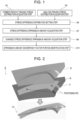
- a stress that contributed to springback (hereinafter also referred to as a driving stress distribution) in a CAE analysis and in an actual panel was obtained with respect to the press-formed product 10 that is illustrated in Fig. 2 and whose cross-sectional shape is a hat-like shape, and the difference between the driving stress distribution in the CAE analysis and the driving stress distribution in the actual panel (hereinafter also referred to as a stress difference distribution) was calculated. Then, a springback analysis was performed by replacing the stress difference distribution with the stress distribution at the forming bottom dead center of the CAE analysis (the details of a method of calculating a driving stress will be described in the embodiment described later).
- bottom dead center refers to the state in which a punch and a die are in contact with each other with a blank interposed therebetween (the state in which forming is completed in a CAE analysis).
- forming bottom dead center refers to the state in which forming is completed with an actual press die.
- analysis bottom dead center refers to the state in which forming is completed in a CAE analysis.
- the springback amount discrepancy factor portion identification method when there is a discrepancy between the amount of springback in a press-formed product, which is formed by press-forming an actual panel, and the amount of springback in a springback analysis, a portion of the shape of the formed product that is a factor causing this springback-amount discrepancy is identified. As illustrated in Fig.
- the springback amount discrepancy factor portion identification method includes a formed product driving stress distribution acquisition step S1, an analysis driving stress distribution acquisition step S3, a stress difference distribution setting step S5, a stress difference springback amount acquisition step S7, a changed stress difference springback amount acquisition step S9, and a springback amount discrepancy factor portion identification step S11.
- a press forming analysis in which a blank model 9 that is a work material (a steel sheet) is sandwiched by a die model 3 that includes a die 5 and a punch 7 is performed.
- the blank model 9 is fixed in place by positioning pins in the forming process as illustrated in Fig. 2 , and the element size of the blank model 9 is set to about 1 mm.
- the friction coefficient between the blank model 9 and the die model 3 was set to 0.15, and the forming bottom dead center was positioned such that the gap between the upper and lower die models was 1.45 mm.
- As the work material a 980 MPa class GA steel sheet having a sheet thickness of 1.4 mm was used.
- the actual panel in the present embodiment is formed by press forming performed under conditions that are the same as the forming conditions set in the CAE analysis.
- the formed product driving stress distribution acquisition step S1 is a step of acquiring a driving stress distribution in the actual panel.
- the actual panel is formed by performing press forming under conditions the same as the forming conditions such as those mentioned above that are set in the CAE analysis.
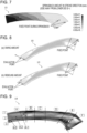
- a press-formed product model is generated from three-dimensional shape measurement data that is obtained by measuring the surface shape of the actual panel that has been released from the die model, and a mechanical analysis in the state where the press-formed product model is sandwiched by the die model 3 illustrated in Fig. 2 to the forming bottom dead center is performed so as to obtain a stress distribution such as that illustrated in Fig. 4 .
- an elastic finite element analysis is performed.
- the stress distribution obtained by the elastic finite element analysis corresponds to the stress contributed to the springback of the actual panel, that is, the driving stress of the actual panel.
- Patent Literature 3 can be used as a specific method for measuring the three-dimensional shape of the actual panel, generating the press-formed product model, and performing the elastic finite element analysis.
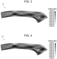
- the analysis driving stress distribution acquisition step S3 is a step of acquiring a stress distribution at the bottom dead center in the CAE analysis (springback analysis) and the residual stress after the press-formed product is released from the die model and acquiring the driving stress in the CAE analysis from the difference between the obtained stress distribution at the bottom dead center and the obtained residual stress.
- the CAE analysis was performed by using the die model 3 and the blank model 9 illustrated in Fig. 2 , the stress of the press-formed product before the press-formed product is released from the die (the bottom dead center) and the residual stress of the press-formed product after the press-formed product has been released from the die (after the occurrence of springback) are obtained, and the driving stress distribution (hereinafter also simply referred to as "stress distribution") in the CAE analysis such as that illustrated in Fig. 3 is calculated by subtracting the residual stress after the press-formed product has been released from the die from the stress at the bottom dead center.
- a computer performs the CAE analysis.
- CAE analysis for example, finite element method analysis software can be used.
- the computer executed LS-DYNA Ver. 971, which is a commercially available finite element method analysis software, so as to perform an analysis, and a dynamic explicit method was applied to a solver.
- the present invention is not limited to the case in which the die model 3 such as that illustrated in Fig. 2 is used and the case in which the press-formed product 10, whose cross-sectional shape is a hat-like shape, is a forming target, and a die model, a press-formed product, and so forth can be suitably set in accordance with the forming target.
- the entire stress distribution at the analysis bottom dead center contributes to springback, and the stress distribution at the bottom dead center may be used as the analysis driving stress distribution.
- the stress difference distribution setting step S5 is a step of calculating the difference between the stress distribution calculated in the analysis driving stress distribution acquisition step S3 ( Fig. 3 and Fig. 5(a) ) and the stress distribution calculated in the formed product driving stress distribution acquisition step S1 ( Fig. 4 and Fig. 5(b) ) as a stress difference distribution and setting the calculated stress difference distribution as the stress distribution in a bottom dead center shape of the CAE analysis.
- the stress difference springback amount acquisition step S7 is a step of performing a springback analysis by using the stress difference distribution set in the stress difference distribution setting step S5 and calculating the amount of springback that occurs in the springback analysis.
- the springback analysis is performed on the press-formed product 10 ( Fig. 6(a) ) having the bottom dead center shape in which the stress difference distribution is set, and displacement after the springback ( Fig. 6(b) ) is calculated by the springback analysis.
- the springback analysis as illustrated in Fig. 7 , three points on one end side of the formed product were set as fixed points, and displacement caused by the springback was calculated.
- the amount of swing ( Fig. 8(a) ) and the amount of rebound ( Fig. 8(b) ) were calculated on the basis of the displacement calculated by the springback analysis.
- the amount of swing was set as the amount of movement in the direction of an arrow in Fig. 8(a) (the direction of the arrow corresponding to a positive direction) caused by the springback at either of two evaluation points set on the other end side of the press-formed product 10, and as illustrated in Fig. 8(b) , the amount of rebound was set as the amount of displacement in the forming stroke direction at the midpoint of the two evaluation points (the direction away from the die 5 corresponding to the positive direction).
- the changed stress difference springback amount acquisition step S9 is a step of changing the stress difference value in a portion of the press-formed product 10 in the stress difference distribution set in the stress difference distribution setting step S5 and performing a springback analysis using the stress difference distribution in which the change is made (a changed stress difference distribution) so as to calculate the amount of springback that occurs in the springback analysis.
- the press-formed product 10 is divided into a plurality of regions (six regions A to F in the longitudinal direction and three regions 1 to 3 in the width direction), and the stress difference in each region is eliminated, that is, the stress difference value in each region is set to zero. Note that the number of regions in which the stress difference is to be eliminated does not need to be one, and the stress differences in a plurality of regions may be eliminated.
- a springback analysis is performed so as to calculate the amount of swing and the amount of rebound illustrated in Fig. 8 as the amount of springback.
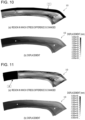
- Fig. 10 illustrates displacement that is calculated by eliminating the stress difference in a region 1 (see Fig. 10(a) ) from the stress difference distribution set in the stress difference distribution setting step S5 (setting the stress difference value to zero) and performing a springback analysis (see Fig. 10(b) ).
- the amount of springback (the amount of swing and the amount of rebound) was calculated on the basis of the calculated displacement.
- the amount of springback in a region 2 and the amount of springback in a region 3 were also calculated (not illustrated).
- Fig. 11 illustrates displacement that is calculated eliminating the stress difference in a region A (see Fig. 11(a) ) from the stress difference distribution set in the stress difference distribution setting step S5 (setting the stress difference value to zero) and performing a springback analysis (see Fig. 11(b) ).
- the amount of springback (the amount of swing and the amount of rebound) was calculated on the basis of the calculated displacement.
- the amount of springback in each of regions B to F was also calculated (not illustrated).
- Fig. 12 illustrates displacement that is calculated by eliminating the stress difference in a region A-1 (see Fig. 12(a) ) from the stress difference distribution set in the stress difference distribution setting step S5 (setting the stress difference value to zero) and performing a springback analysis (see Fig. 12(b))
- Fig. 13 illustrates displacement that is calculated by eliminating the stress difference in a region A-3 (see Fig. 13(a) ) from the stress difference distribution set in the stress difference distribution setting step S5 (setting the stress difference value to zero) and performing a springback analysis (see Fig. 13(b) ).
- the amount of springback (the amount of swing and the amount of rebound) was calculated on the basis of the calculated displacement.
- the amount of springback in each of regions A-1 to F-3 was also calculated (not illustrated).
- the springback amount discrepancy factor portion identification step S11 is a step of identifying a portion that is a factor causing a discrepancy in springback amount between the CAE analysis and the actual panel on the basis of the amount of springback calculated in the stress difference springback amount acquisition step S7 and the amount of springback calculated in the changed stress difference springback amount acquisition step S9.
- Fig. 14 illustrates results of the amounts of swing calculated in the stress difference springback amount acquisition step S7 and the changed stress difference springback amount acquisition step S9.
- base is the amount of swing by the stress difference distribution in which elimination of stress is not performed
- first and second are each the amount of swing by the changed stress difference distribution in which the stress difference in each region is eliminated.
- the amount of swing (base) in the case where the stress difference is not changed is -10.7 mm.
- the amounts of swing in the stress eliminating regions which are the regions 1 to 3, it is understood that there is a large change from the base only in the region 2 compared with the regions 1 and 3.
- the amount of swing in the region D-2 and the amount of swing in the region E-2 are reduced to be smaller than that in the base without stress elimination is not performed.
- the fact that the amount of swing is reduced by eliminating the stress difference in a certain region indicates that this region has a great influence on the discrepancy in the amount of swing.
- the amount of swing in each region other than the region D-2 and the region E-2 is approximately equal to the amount of swing (base) when the stress difference is not changed, and thus, these regions are determined as portions each having a small influence on the discrepancy in swing amount between the CAE analysis and the actual panel.
- the amount of rebound (base) when the stress difference is not changed is 4.2 mm.
- the amounts of rebound in the stress eliminating regions which are the regions 1 to 3, it is understood that there is a large change from the base only in the region 2 (-8.3 mm) compared with the region 1 (4.8 mm) and the region 3 (7.5 mm) .
- the amount of rebound is -4.6 mm, and compared to a rebound amount of 4.2 mm in the base without stress elimination, the rebound direction is opposite to that in the base. In addition, the rebound amount is increased.
- the region D-2 is a portion that is more likely to cause a discrepancy in rebound amount.
- the region D-2 is a portion that suppresses, as a result of the stress difference being therein, a discrepancy in rebound amount and is not a portion that causes such a discrepancy.
- the region D-2 and the region E-2 in the press-formed product 10 were identified as portions that were factors causing a discrepancy in swing amount between the CAE analysis and the actual panel.
- the region F-2 was identified as a portion that was a factor causing a discrepancy in rebound amount. Accordingly, the driving stress in each of the identified portions in the driving stress distribution (see Fig. 3 ) obtained by the CAE analysis was replaced with the corresponding driving stress distribution in each portion of the actual panel, and a springback analysis was performed so as to determine whether the discrepancy in springback amount was reduced.
- Fig. 16 illustrates the result obtained by determining whether the discrepancy in swing amount between the CAE analysis and the actual panel is reduced.
- Fig. 16 is a graph illustrating the result (the discrepancy amount) obtained by subtracting the swing amount in the actual panel from the swing amount in the CAE analysis, and the vertical axis denotes discrepancy amount, and the horizontal axis denotes stress replacement region.
- “NONE” is the case where there is no stress replacement region, and in this case, the discrepancy amount is -11.6 mm, which is the difference between the CAE analysis and the actual panel.
- ALL is the case where all the regions of the driving stress distribution of the CAE analysis are replaced with the driving stress distribution of the actual panel, and in this case, the discrepancy amount is substantially zero.
- Fig. 17 illustrates the result obtained by determining whether the discrepancy in rebound amount between the CAE analysis and the actual panel is reduced. Also regarding the discrepancy in rebound amount, as denoted by "F-2", the discrepancy in rebound amount between the CAE analysis and the actual panel was reduced by replacing the stress distribution of the region F-2 at the forming bottom dead center with the stress distribution of the actual panel.
- the portion identified by the springback amount discrepancy factor portion identification method according to the present embodiment is reasonable to be a portion that is a factor causing the discrepancy in springback amount between the CAE analysis and the actual panel.
- the adjustment operation for the die, the forming conditions, or the like performed in order to bring the shape obtained by the CAE analysis and the shape of the actual panel after the actual panel has been released from the die close to each other can be efficiently performed.
- the reproducibility of the springback analysis can be improved by reviewing the settings on the CAE analysis and the shape of the die focusing on the identified portion, and the usefulness of the measures against springback that are based on the CAE analysis can be ensured.
- a stress difference distribution is changed by eliminating the stress difference in at least one region (by setting all components to zero)
- the method of changing a stress difference distribution is not limited to this, and a stress difference distribution may be changed by eliminating a component in at least one direction from the stress difference distribution, multiplying the component in the at least one direction by a constant in the stress difference distribution, adding a constant to the component in the at least one direction in the stress difference distribution, raising the component in the at least one direction to the power of a constant in the stress difference distribution, replacing the component in the at least one direction in the stress difference distribution with an average value in a sheet thickness direction of a work material, or replacing the component in the at least one direction in the stress difference distribution with a median value in the sheet thickness direction of the work material.
- the springback amount discrepancy factor portion identification method described in the first embodiment can be realized by causing a personal computer (PC) to execute a preset program.
- PC personal computer
- An example of such an apparatus will now be described in the second embodiment.
- a springback amount discrepancy factor portion identification apparatus 11 includes a display device 13, an input device 15, a main memory 17, an auxiliary memory 19, and an arithmetic processing unit 21, each of which is illustrated in Fig. 18 as an example.
- the display device 13, the input device 15, the main memory 17, and the auxiliary memory 19 are connected to the arithmetic processing unit 21 and perform functions in response to a command from the arithmetic processing unit 21.
- the display device 13 is used for displaying an execution result or the like and is formed of, for example, a liquid crystal monitor.
- the input device 15 is used by an operator who performs an input operation or the like and is formed of, for example, a keyboard or a mouse.
- the main memory 17 is used for temporarily storing data used by the arithmetic processing unit 21, performing a calculation, or the like and is formed of, for example, RAM.
- the auxiliary memory 19 is used for storing data or the like and is formed of, for example, a hard disk.
- the auxiliary memory 19 stores at least three-dimensional shape measurement data 23 and various data items that are required for a CAE analysis of a die model 25 or the like.
- the arithmetic processing unit 21 is formed of, for example, a CPU such as a PC. As a result of the arithmetic processing unit 21 executing preset programs, formed product driving stress distribution acquisition means 27, analysis driving stress distribution acquisition means 29, stress difference distribution setting means 31, stress difference springback amount acquisition means 33, changed stress difference springback amount acquisition means 35, and springback amount discrepancy factor portion identification means 37 are constructed.
- the formed product driving stress distribution acquisition means 27 performs processing similar to the formed product driving stress distribution acquisition step S1 described in the first embodiment.
- the analysis driving stress distribution acquisition means 29 performs the analysis driving stress distribution acquisition step S3.
- the stress difference distribution setting means 31 performs the stress difference distribution setting step S5.
- the stress difference springback amount acquisition means 33 performs the stress difference springback amount acquisition step S7.
- the changed stress difference springback amount acquisition means 35 performs the changed stress difference springback amount acquisition step S9.
- the springback amount discrepancy factor portion identification means 37 performs the springback amount discrepancy factor portion identification step S11.
- the present invention is applicable not only to an end formed product (the shape of a product) but also to a product in the process of being formed in the case of a press-formed product for which forming processes are performed separately.
- an end formed product the shape of a product
- the present invention is also applicable to an aluminum sheet.
Landscapes
- Engineering & Computer Science (AREA)
- Physics & Mathematics (AREA)
- Theoretical Computer Science (AREA)
- General Physics & Mathematics (AREA)
- Geometry (AREA)
- Evolutionary Computation (AREA)
- Computer Hardware Design (AREA)
- General Engineering & Computer Science (AREA)
- Mechanical Engineering (AREA)
- Pure & Applied Mathematics (AREA)
- Mathematical Optimization (AREA)
- Mathematical Analysis (AREA)
- Computational Mathematics (AREA)
- Shaping Metal By Deep-Drawing, Or The Like (AREA)
Claims (7)
- Computerimplementiertes Verfahren zur Identifizierung eines Rückfederungsbetrags-Diskrepanzfaktors zum Identifizieren eines Abschnitts einer Form eines pressgeformten Produkts, das durch Pressformen einer tatsächlichen Platte geformt wird, wobei der Abschnitt ein Faktor ist, der eine Diskrepanz zwischen einem Rückfederungsbetrag, der in dem pressgeformten Produkt auftritt, und einem Rückfederungsbetrag, der durch eine Rückfederungsanalyse erhalten wird, die an einem Analysemodell mit einer Form, die der Form des pressgeformten Produkts entspricht, durchgeführt wird, verursacht, wobei das Verfahren umfasst:einen Erfassungsschritt für die Antriebsspannungsverteilung des geformten Produkts, bei dem ein Modell des pressgeformten Produkts unter Verwendung von dreidimensionalen Formmessdaten erzeugt wird, die durch Messen einer Oberflächenform des pressgeformten Produkts erhalten werden, nachdem das pressgeformte Produkt aus einer Matrize freigegeben wurde, eine mechanische Analyse in einem Zustand durchgeführt wird, in dem das Modell des pressgeformten Produkts von einem Matrizenmodell bis zu einem unteren Formtotpunkt eingeschlossen ist, und eine Spannungsverteilung am unteren Formtotpunkt als eine Antriebsspannungsverteilung erfasst wird, die zur Rückfederung in dem pressgeformten Produkt beiträgt;einen Analysetriebsspannungsverteilungserfassungsschritt des Erfassens einer Spannungsverteilung am unteren Totpunkt in der Rückfederungsanalyse und einer Restspannungsverteilung, nachdem das pressgeformte Produkt von der Form freigegeben worden ist, und des Erfassens einer Differenz zwischen der Spannungsverteilung am unteren Totpunkt und der Restspannungsverteilung, nachdem das pressgeformte Produkt von der Form freigegeben worden ist, als eine Antriebsspannungsverteilung in der Rückfederungsanalyse;einen Spannungsdifferenzverteilungs-Einstellschritt zum Erhalten einer Spannungsdifferenzverteilung aus einer Differenz zwischen einer Analyse-Antriebsspannungsverteilung, die in dem Analyse-Antriebsspannungsverteilungs-Erfassungsschritt erfasst wird, und einer Formprodukt-Antriebsspannungsverteilung, die in dem Formprodukt-Antriebsspannungsverteilungs-Erfassungsschritt erfasst wird, und Einstellen der Spannungsdifferenzverteilung auf die Form des Formprodukts am unteren Totpunkt in der Rückfederungsanalyse;einen Spannungsdifferenz-Rückfederungsbetrag-Erfassungsschritt des Erfassens eines Rückfederungsbetrags durch Ausführen einer Rückfederungsanalyse auf der Grundlage der eingestellten Spannungsdifferenzverteilung;einen Schritt zum Erfassen eines geänderten Spannungsdifferenz-Rückfederungsbetrags zum Ändern eines Spannungsdifferenzwerts in einem Bereich der Spannungsdifferenzverteilung, die in dem Schritt zum Einstellen der Spannungsdifferenzverteilung eingestellt wurde, und zum Erfassen eines Rückfederungsbetrags durch Ausführen einer Rückfederungsanalyse auf der Grundlage der geänderten Spannungsdifferenzverteilung; undeinen Rückfederungsbetrags-Diskrepanzfaktor-Abschnitt-Identifizierungsschritt des Identifizierens eines Abschnitts einer Form eines geformten Produkts, wobei der Abschnitt ein Faktor ist, der eine Diskrepanz im Rückfederungsbetrag zwischen dem pressgeformten Produkt und der Rückfederungsanalyse verursacht, durch Vergleichen des Rückfederungsbetrags, der in dem veränderten Spannungsdifferenz-Rückfederungsbetrag-Erfassungsschritt erfasst wurde, und des Rückfederungsbetrags, der in dem Spannungsdifferenz-Rückfederungsbetrag-Erfassungsschritt erfasst wurde.
- Computerimplementiertes Verfahren zur Identifizierung des Rückfederungsbetrags-Diskrepanzfaktors nach Anspruch 1,
wobei in dem Schritt der Erfassung des geänderten Spannungsdifferenzrückfederungsbetrags ein Spannungsdifferenzwert geändert wird, indem eine Komponente in mindestens einer Richtung aus der Spannungsdifferenzverteilung eliminiert wird, die Komponente in der mindestens einen Richtung mit einer Konstanten in der Spannungsdifferenzverteilung multipliziert wird, eine Konstante zu der Komponente in der mindestens einen Richtung in der Spannungsdifferenzverteilung addiert wird, Erhöhen der Komponente in der mindestens einen Richtung mit der Potenz einer Konstanten in der Spannungsdifferenzverteilung, Ersetzen der Komponente in der mindestens einen Richtung in der Spannungsdifferenzverteilung durch einen Mittelwert in einer Blechdickenrichtung eines Arbeitsmaterials, oder Ersetzen der Komponente in der mindestens einen Richtung in der Spannungsdifferenzverteilung durch einen Medianwert in der Blechdickenrichtung des Arbeitsmaterials. - Vorrichtung zur Identifizierung eines Diskrepanzfaktors des Rückfederungsbetrags, die einen Abschnitt einer Form eines pressgeformten Produkts identifiziert, das durch Pressformen einer tatsächlichen Platte geformt wird, wobei der Abschnitt ein Faktor ist, der eine Abweichung zwischen einem Rückfederungsbetrag, der in dem pressgeformten Produkt aufgetreten ist, und einem Rückfederungsbetrag verursacht, der durch eine Rückfederungsanalyse erhalten wird, die an einem Analysemodell durchgeführt wird, das eine Form hat, die die gleiche ist wie die Form des pressgeformten Produkts, wobei die Vorrichtung umfasst:Erfassungsmittel für die Antriebsspannungsverteilung des geformten Produkts zum Erzeugen eines Modells eines pressgeformten Produkts unter Verwendung dreidimensionaler Formmessdaten, die durch Messen einer Oberflächenform des pressgeformten Produkts erhalten werden, nachdem das pressgeformte Produkt aus einer Matrize freigegeben wurde, Durchführen einer mechanischen Analyse in einem Zustand, in dem das Modell des pressgeformten Produkts durch ein Matrizenmodell bis zu einem unteren Formtotpunkt eingeschlossen ist, und Erfassen einer Spannungsverteilung am unteren Formtotpunkt als eine Antriebsspannungsverteilung, die zur Rückfederung in dem pressgeformten Produkt beiträgt;Analyse-Antriebsspannungsverteilungs-Erfassungsmittel zum Erfassen einer Spannungsverteilung an dem unteren Totpunkt in der Rückfederungsanalyse und einer Restspannungsverteilung, nachdem das pressgeformte Produkt von der Matrize freigegeben worden ist, und zum Erfassen einer Differenz zwischen der Spannungsverteilung an dem unteren Totpunkt und der Restspannungsverteilung, nachdem das pressgeformte Produkt von der Matrize freigegeben worden ist, als eine Antriebsspannungsverteilung in der Rückfederungsanalyse;Spannungsdifferenzverteilungs-Einstellmittel zum Erhalten einer Spannungsdifferenzverteilung aus einer Differenz zwischen einer Analyse-Antriebsspannungsverteilung, die durch das Analyse-Antriebsspannungsverteilungs-Erfassungsmittel erfasst wird, und einer Antriebsspannungsverteilung des geformten Produkts, die durch das Antriebsspannungsverteilungs-Erfassungsmittel des geformten Produkts erfasst wird, und zum Einstellen der Spannungsdifferenzverteilung auf die Form des geformten Produkts am unteren Totpunkt in der Rückfederungsanalyse;Spannungsdifferenz-Rückfederungsbetrag-Erfassungsmittel zum Erfassen eines Rückfederungsbetrags durch Ausführen einer Rückfederungsanalyse auf der Grundlage der eingestellten Spannungsdifferenzverteilung;Erfassungsmittel für einen geänderten Spannungsdifferenz-Rückfederungsbetrag zum Ändern eines Spannungsdifferenzwertes in einem Bereich der Spannungsdifferenzverteilung, die durch das Einstellmittel für die Spannungsdifferenzverteilung eingestellt ist, und zum Erfassen eines Rückfederungsbetrages durch Ausführen einer Rückfederungsanalyse auf der Grundlage der geänderten Spannungsdifferenzverteilung; undRückfederungsbetrag-Diskrepanzfaktor-Abschnitts-Identifizierungsmittel zum Identifizieren eines Abschnitts einer Form eines geformten Produkts, wobei der Abschnitt ein Faktor ist, der eine Diskrepanz im Rückfederungsbetrag zwischen dem pressgeformten Produkt und der Rückfederungsanalyse verursacht, durch Vergleichen des Rückfederungsbetrags, der durch das veränderte Spannungsdifferenz-Rückfederungsbetrag-Erfassungsmittel erfasst wird, und des Rückfederungsbetrags, der durch das Spannungsdifferenz-Rückfederungsbetrag-Erfassungsmittel erfasst wird.
- Vorrichtung zur Identifizierung eines Diskrepanzfaktors des Rückfederungsbetrags nach Anspruch 3,
wobei die Erfassungseinrichtung für den geänderten Spannungsdifferenz-Rückfederungsbetrag einen Spannungsdifferenzwert ändert, indem sie eine Komponente in mindestens einer Richtung aus der Spannungsdifferenzverteilung eliminiert, die Komponente in der mindestens einen Richtung mit einer Konstanten in der Spannungsdifferenzverteilung multipliziert, eine Konstante zu der Komponente in der mindestens einen Richtung in der Spannungsdifferenzverteilung addiert, Erhöhen der Komponente in der mindestens einen Richtung mit der Potenz einer Konstanten in der Spannungsdifferenzverteilung, Ersetzen der Komponente in der mindestens einen Richtung in der Spannungsdifferenzverteilung durch einen Mittelwert in einer Blechdickenrichtung eines Arbeitsmaterials, oder Ersetzen der Komponente in der mindestens einen Richtung in der Spannungsdifferenzverteilung durch einen Medianwert in der Blechdickenrichtung des Arbeitsmaterials. - Programm zur Identifizierung eines Rückfederungsbetrags-Diskrepanzfaktors, das einen Abschnitt einer Form eines pressgeformten Produkts identifiziert, das durch Pressformen einer tatsächlichen Platte gebildet wird, wobei der Abschnitt ein Faktor ist, der eine Diskrepanz zwischen einem Rückfederungsbetrag, der in dem pressgeformten Produkt aufgetreten ist, und einem Rückfederungsbetrag verursacht, der durch eine Rückfederungsanalyse erhalten wird, die an einem Analysemodell durchgeführt wird, das die gleiche Form wie die Form des pressgeformten Produkts hat,
das Programm Anweisungen umfasst, die, wenn sie von einer arithmetischen Verarbeitungseinheit in einem Computer ausgeführt werden, den Computer veranlassen, die folgenden Schritte auszuführen:Erfassungsschritte für die Antriebsspannungsverteilung des geformten Produkts zum Erzeugen eines Modells eines pressgeformten Produkts unter Verwendung dreidimensionaler Formmessdaten, die durch Messen einer Oberflächenform des pressgeformten Produkts erhalten werden, nachdem das pressgeformte Produkt aus einer Matrize freigegeben wurde, Durchführen einer mechanischen Analyse in einem Zustand, in dem das Modell des pressgeformten Produkts durch ein Matrizenmodell bis zu einem unteren Formtotpunkt eingeschlossen ist, und Erfassen einer Spannungsverteilung am unteren Formtotpunkt als eine Antriebsspannungsverteilung, die zur Rückfederung in dem pressgeformten Produkt beiträgt;Analysetriebsspannungsverteilungserfassungsschritt zum Erfassen einer Spannungsverteilung an dem unteren Totpunkt in der Rückfederungsanalyse und einer Restspannungsverteilung, nachdem das pressgeformte Produkt von der Matrize freigegeben worden ist, und Erfassen einer Differenz zwischen der Spannungsverteilung an dem unteren Totpunkt und der Restspannungsverteilung, nachdem das pressgeformte Produkt von der Matrize freigegeben worden ist, als eine Antriebsspannungsverteilung in der Rückfederungsanalyse;Spannungsdifferenzverteilungs-Einstellschritt zum Erhalten einer Spannungsdifferenzverteilung aus einer Differenz zwischen einer Analyse-Antriebsspannungsverteilung, die durch den Analyse-Antriebsspannungsverteilungs-Erfassungsschritt erfasst wird, und einer Formprodukt-Antriebsspannungsverteilung, die durch den Formprodukt-Antriebsspannungsverteilungs-Erfassungsschritt erfasst wird, und Einstellen der Spannungsdifferenzverteilung auf die Form des Formprodukts am unteren Totpunkt bei der Rückfederungsanalyse;Spannungsdifferenz-Rückfederungsbetrag-Erfassungsschritt zum Erfassen eines Rückfederungsbetrags durch Ausführen einer Rückfederungsanalyse auf der Grundlage der eingestellten Spannungsdifferenzverteilung;Erfassungsschritt für einen geänderten Spannungsdifferenz-Rückfederungsbetrag zum Ändern eines Spannungsdifferenzwertes in einem Bereich der Spannungsdifferenzverteilung, die durch den Schritt des Einstellens der Spannungsdifferenzverteilung eingestellt wird, und zum Erfassen eines Rückfederungsbetrages durch Ausführen einer Rückfederungsanalyse auf der Grundlage der geänderten Spannungsdifferenzverteilung; undRückfederungsbetrag-Diskrepanzfaktor-Abschnitt-Identifizierungsschrittzum Identifizieren eines Abschnitts einer Form eines geformten Produkts, wobei der Abschnitt ein Faktor ist, der eine Diskrepanz im Rückfederungsbetrag zwischen dem pressgeformten Produkt und der Rückfederungsanalyse verursacht, durch Vergleichen des Rückfederungsbetrags, der durch den veränderten Spannungsdifferenz-Rückfederungsbetrag-Erfassungsschritt erfasst wird, und des Rückfederungsbetrags, der durch den Spannungsdifferenz-Rückfederungsbetrag-Erfassungsschritt erfasst wird. - Programm nach Anspruch 5,
wobei der Schritt der geänderten Spannungsdifferenz-Rückfederungsbetragserfassung einen Spannungsdifferenzwert ändert, indem eine Komponente in mindestens einer Richtung aus der Spannungsdifferenzverteilung eliminiert wird, die Komponente in der mindestens einen Richtung mit einer Konstanten in der Spannungsdifferenzverteilung multipliziert wird, eine Konstante zu der Komponente in der mindestens einen Richtung in der Spannungsdifferenzverteilung addiert wird, Erhöhen der Komponente in der mindestens einen Richtung mit der Potenz einer Konstanten in der Spannungsdifferenzverteilung, Ersetzen der Komponente in der mindestens einen Richtung in der Spannungsdifferenzverteilung durch einen Mittelwert in einer Blechdickenrichtung eines Arbeitsmaterials, oder Ersetzen der Komponente in der mindestens einen Richtung in der Spannungsdifferenzverteilung durch einen Medianwert in der Blechdickenrichtung des Arbeitsmaterials. - Computerlesbarer Datenträger, auf dem das Programm nach Anspruch 5 oder 6 gespeichert ist.
Applications Claiming Priority (2)
| Application Number | Priority Date | Filing Date | Title |
|---|---|---|---|
| JP2019083661A JP6852750B2 (ja) | 2019-04-25 | 2019-04-25 | スプリングバック量乖離要因部位特定方法および装置 |
| PCT/JP2020/016698 WO2020218145A1 (ja) | 2019-04-25 | 2020-04-16 | スプリングバック量乖離要因部位特定方法および装置 |
Publications (3)
| Publication Number | Publication Date |
|---|---|
| EP3960320A1 EP3960320A1 (de) | 2022-03-02 |
| EP3960320A4 EP3960320A4 (de) | 2022-07-13 |
| EP3960320B1 true EP3960320B1 (de) | 2024-08-14 |
Family
ID=72941894
Family Applications (1)
| Application Number | Title | Priority Date | Filing Date |
|---|---|---|---|
| EP20795399.3A Active EP3960320B1 (de) | 2019-04-25 | 2020-04-16 | Verfahren und gerät zur identifizierung eines rückfederungsmassabweichungsfaktors |
Country Status (7)
| Country | Link |
|---|---|
| US (1) | US12151273B2 (de) |
| EP (1) | EP3960320B1 (de) |
| JP (1) | JP6852750B2 (de) |
| KR (1) | KR102549984B1 (de) |
| CN (1) | CN113727790B (de) |
| MX (1) | MX2021012954A (de) |
| WO (1) | WO2020218145A1 (de) |
Families Citing this family (6)
| Publication number | Priority date | Publication date | Assignee | Title |
|---|---|---|---|---|
| JP6841295B2 (ja) * | 2019-05-22 | 2021-03-10 | Jfeスチール株式会社 | スプリングバック量乖離要因部位特定方法および装置 |
| JP7243657B2 (ja) * | 2020-02-14 | 2023-03-22 | Jfeスチール株式会社 | プレス成形品の形状変化予測方法 |
| JP6888703B1 (ja) * | 2020-02-14 | 2021-06-16 | Jfeスチール株式会社 | プレス成形品の形状変化予測方法 |
| JP7533491B2 (ja) * | 2022-01-13 | 2024-08-14 | Jfeスチール株式会社 | プレス成形品のスプリングバック量評価方法、装置及びプログラム |
| CN114571124B (zh) * | 2022-04-07 | 2024-01-30 | 三一技术装备有限公司 | 电芯焊接位置确定方法及电池模组的制备方法 |
| JP7726433B1 (ja) * | 2024-06-28 | 2025-08-20 | Jfeスチール株式会社 | 寸法変動要因解析方法、寸法変動要因解析装置、寸法変動要因解析プログラム、及びプレス成形品の製造方法 |
Family Cites Families (16)
| Publication number | Priority date | Publication date | Assignee | Title |
|---|---|---|---|---|
| JPS6060798A (ja) * | 1983-09-14 | 1985-04-08 | 松下電器産業株式会社 | 電子機器取付装置 |
| JP2554368Y2 (ja) * | 1992-03-16 | 1997-11-17 | 関東自動車工業株式会社 | プレス製品の残留応力解析装置 |
| JP4352658B2 (ja) * | 2002-05-29 | 2009-10-28 | Jfeスチール株式会社 | プレス成形品のスプリングバック解析方法 |
| JP4894294B2 (ja) | 2006-02-27 | 2012-03-14 | Jfeスチール株式会社 | プレス成形解析方法 |
| CN103995927B (zh) * | 2006-08-31 | 2017-01-04 | 新日铁住金株式会社 | 回弹对策位置特定方法以及回弹对策位置特定装置 |
| JP4724626B2 (ja) * | 2006-08-31 | 2011-07-13 | 新日本製鐵株式会社 | スプリングバック発生原因部位特定方法、その装置、及びそのプログラム |
| JP5765014B2 (ja) | 2011-03-30 | 2015-08-19 | Jfeスチール株式会社 | プレス成形解析方法 |
| JP5821403B2 (ja) | 2011-08-22 | 2015-11-24 | Jfeスチール株式会社 | プレス成形品のスプリングバック対策効果確認方法及び装置 |
| JP5834698B2 (ja) * | 2011-09-26 | 2015-12-24 | Jfeスチール株式会社 | プレス成形におけるスプリングバック要因分析方法及び装置 |
| JP6064447B2 (ja) * | 2012-08-31 | 2017-01-25 | Jfeスチール株式会社 | スプリングバック抑制対策部品製造方法 |
| JP6060591B2 (ja) * | 2012-09-26 | 2017-01-18 | Jfeスチール株式会社 | プレス成形品のスプリングバック要因特定方法および装置 |
| JP5582211B1 (ja) * | 2013-03-14 | 2014-09-03 | Jfeスチール株式会社 | 応力−ひずみ関係シミュレート方法、スプリングバック量予測方法およびスプリングバック解析装置 |
| JP5987852B2 (ja) * | 2013-05-16 | 2016-09-07 | Jfeスチール株式会社 | スプリングバック量評価方法 |
| JP6152841B2 (ja) * | 2014-10-31 | 2017-06-28 | Jfeスチール株式会社 | プレス成形方法およびプレス成形用金型の製造方法 |
| JP6149843B2 (ja) | 2014-11-04 | 2017-06-21 | Jfeスチール株式会社 | プレス成形品の形状矯正解析方法及び装置、プレス成形品の形状矯正方法 |
| JP6519639B1 (ja) | 2017-12-07 | 2019-05-29 | Jfeスチール株式会社 | スプリングバック量変動要因部位特定方法 |
-
2019
- 2019-04-25 JP JP2019083661A patent/JP6852750B2/ja active Active
-
2020
- 2020-04-16 EP EP20795399.3A patent/EP3960320B1/de active Active
- 2020-04-16 MX MX2021012954A patent/MX2021012954A/es unknown
- 2020-04-16 KR KR1020217034409A patent/KR102549984B1/ko active Active
- 2020-04-16 WO PCT/JP2020/016698 patent/WO2020218145A1/ja not_active Ceased
- 2020-04-16 US US17/606,202 patent/US12151273B2/en active Active
- 2020-04-16 CN CN202080030142.6A patent/CN113727790B/zh active Active
Also Published As
| Publication number | Publication date |
|---|---|
| JP2020179409A (ja) | 2020-11-05 |
| JP6852750B2 (ja) | 2021-03-31 |
| EP3960320A1 (de) | 2022-03-02 |
| CN113727790B (zh) | 2023-03-28 |
| MX2021012954A (es) | 2022-01-31 |
| CN113727790A (zh) | 2021-11-30 |
| KR20210141681A (ko) | 2021-11-23 |
| EP3960320A4 (de) | 2022-07-13 |
| US12151273B2 (en) | 2024-11-26 |
| US20220219217A1 (en) | 2022-07-14 |
| KR102549984B1 (ko) | 2023-06-29 |
| WO2020218145A1 (ja) | 2020-10-29 |
Similar Documents
| Publication | Publication Date | Title |
|---|---|---|
| EP3960320B1 (de) | Verfahren und gerät zur identifizierung eines rückfederungsmassabweichungsfaktors | |
| JP4410833B2 (ja) | スプリングバック発生原因分析方法、その装置、そのプログラム及び記録媒体 | |
| EP3991872B1 (de) | Verfahren zur ursachenanalyse von rückfederungsvariationen | |
| US11911816B2 (en) | Method for identifying variation factor portion of springback amount | |
| US20160288184A1 (en) | Method for Bending Metal Sheet to Achieve High Angle Accuracy | |
| JP5910224B2 (ja) | プレス成形解析方法 | |
| WO2010073756A1 (ja) | スプリングバック発生原因分析方法、スプリングバック発生原因分析装置、スプリングバック発生原因分析プログラム及び記録媒体 | |
| US10161892B2 (en) | Method of analyzing press forming | |
| JP6655105B2 (ja) | 製造補助装置 | |
| Wang et al. | Springback compensation of automotive panel based on three-dimensional scanning and reverse engineering | |
| CN104755187B (zh) | 回弹量评价方法 | |
| Solhjoo | A note on “Barrel Compression Test”: A method for evaluation of friction | |
| JP6841295B2 (ja) | スプリングバック量乖離要因部位特定方法および装置 | |
| JP2016020000A (ja) | 見込み金型形状作成方法及び装置 | |
| JP5737059B2 (ja) | プレス成形シミュレーション解析方法及び装置 | |
| JP5861344B2 (ja) | プレス成形解析方法 | |
| JP2005177837A (ja) | 成形加工シミュレーションにおける面形状歪み量演算方法及びその装置 | |
| JP2023102880A (ja) | プレス成形品のスプリングバック量評価方法、装置及びプログラム | |
| JP2006341295A (ja) | プレス成形品の面ひずみ予測方法および装置 | |
| WO2026004219A1 (ja) | 寸法変動要因解析方法、寸法変動要因解析装置、寸法変動要因解析プログラム、及びプレス成形品の製造方法 | |
| JP2020144819A (ja) | 形状不良発生原因分析方法、形状不良修正方法、形状不良発生原因分析装置、形状不良発生原因を分析するためのプログラムおよび記録媒体 |
Legal Events
| Date | Code | Title | Description |
|---|---|---|---|
| STAA | Information on the status of an ep patent application or granted ep patent |
Free format text: STATUS: THE INTERNATIONAL PUBLICATION HAS BEEN MADE |
|
| PUAI | Public reference made under article 153(3) epc to a published international application that has entered the european phase |
Free format text: ORIGINAL CODE: 0009012 |
|
| STAA | Information on the status of an ep patent application or granted ep patent |
Free format text: STATUS: REQUEST FOR EXAMINATION WAS MADE |
|
| 17P | Request for examination filed |
Effective date: 20211125 |
|
| AK | Designated contracting states |
Kind code of ref document: A1 Designated state(s): AL AT BE BG CH CY CZ DE DK EE ES FI FR GB GR HR HU IE IS IT LI LT LU LV MC MK MT NL NO PL PT RO RS SE SI SK SM TR |
|
| A4 | Supplementary search report drawn up and despatched |
Effective date: 20220610 |
|
| RIC1 | Information provided on ipc code assigned before grant |
Ipc: G06F 119/14 20200101ALN20220603BHEP Ipc: G06F 113/24 20200101ALN20220603BHEP Ipc: B21D 22/02 20060101ALI20220603BHEP Ipc: B30B 15/26 20060101ALI20220603BHEP Ipc: G06F 30/10 20200101ALI20220603BHEP Ipc: G06F 30/23 20200101ALI20220603BHEP Ipc: B21D 22/00 20060101AFI20220603BHEP |
|
| DAV | Request for validation of the european patent (deleted) | ||
| DAX | Request for extension of the european patent (deleted) | ||
| GRAP | Despatch of communication of intention to grant a patent |
Free format text: ORIGINAL CODE: EPIDOSNIGR1 |
|
| STAA | Information on the status of an ep patent application or granted ep patent |
Free format text: STATUS: GRANT OF PATENT IS INTENDED |
|
| INTG | Intention to grant announced |
Effective date: 20240408 |
|
| GRAS | Grant fee paid |
Free format text: ORIGINAL CODE: EPIDOSNIGR3 |
|
| GRAA | (expected) grant |
Free format text: ORIGINAL CODE: 0009210 |
|
| STAA | Information on the status of an ep patent application or granted ep patent |
Free format text: STATUS: THE PATENT HAS BEEN GRANTED |
|
| AK | Designated contracting states |
Kind code of ref document: B1 Designated state(s): AL AT BE BG CH CY CZ DE DK EE ES FI FR GB GR HR HU IE IS IT LI LT LU LV MC MK MT NL NO PL PT RO RS SE SI SK SM TR |
|
| REG | Reference to a national code |
Ref country code: GB Ref legal event code: FG4D |
|
| REG | Reference to a national code |
Ref country code: CH Ref legal event code: EP |
|
| REG | Reference to a national code |
Ref country code: DE Ref legal event code: R096 Ref document number: 602020035856 Country of ref document: DE |
|
| REG | Reference to a national code |
Ref country code: IE Ref legal event code: FG4D |
|
| REG | Reference to a national code |
Ref country code: LT Ref legal event code: MG9D |
|
| REG | Reference to a national code |
Ref country code: NL Ref legal event code: MP Effective date: 20240814 |
|
| PG25 | Lapsed in a contracting state [announced via postgrant information from national office to epo] |
Ref country code: NO Free format text: LAPSE BECAUSE OF FAILURE TO SUBMIT A TRANSLATION OF THE DESCRIPTION OR TO PAY THE FEE WITHIN THE PRESCRIBED TIME-LIMIT Effective date: 20241114 |
|
| REG | Reference to a national code |
Ref country code: AT Ref legal event code: MK05 Ref document number: 1712819 Country of ref document: AT Kind code of ref document: T Effective date: 20240814 |
|
| PG25 | Lapsed in a contracting state [announced via postgrant information from national office to epo] |
Ref country code: NL Free format text: LAPSE BECAUSE OF FAILURE TO SUBMIT A TRANSLATION OF THE DESCRIPTION OR TO PAY THE FEE WITHIN THE PRESCRIBED TIME-LIMIT Effective date: 20240814 Ref country code: FI Free format text: LAPSE BECAUSE OF FAILURE TO SUBMIT A TRANSLATION OF THE DESCRIPTION OR TO PAY THE FEE WITHIN THE PRESCRIBED TIME-LIMIT Effective date: 20240814 Ref country code: PL Free format text: LAPSE BECAUSE OF FAILURE TO SUBMIT A TRANSLATION OF THE DESCRIPTION OR TO PAY THE FEE WITHIN THE PRESCRIBED TIME-LIMIT Effective date: 20240814 Ref country code: GR Free format text: LAPSE BECAUSE OF FAILURE TO SUBMIT A TRANSLATION OF THE DESCRIPTION OR TO PAY THE FEE WITHIN THE PRESCRIBED TIME-LIMIT Effective date: 20241115 Ref country code: PT Free format text: LAPSE BECAUSE OF FAILURE TO SUBMIT A TRANSLATION OF THE DESCRIPTION OR TO PAY THE FEE WITHIN THE PRESCRIBED TIME-LIMIT Effective date: 20241216 |
|
| PG25 | Lapsed in a contracting state [announced via postgrant information from national office to epo] |
Ref country code: BG Free format text: LAPSE BECAUSE OF FAILURE TO SUBMIT A TRANSLATION OF THE DESCRIPTION OR TO PAY THE FEE WITHIN THE PRESCRIBED TIME-LIMIT Effective date: 20240814 |
|
| PG25 | Lapsed in a contracting state [announced via postgrant information from national office to epo] |
Ref country code: LV Free format text: LAPSE BECAUSE OF FAILURE TO SUBMIT A TRANSLATION OF THE DESCRIPTION OR TO PAY THE FEE WITHIN THE PRESCRIBED TIME-LIMIT Effective date: 20240814 |
|
| PG25 | Lapsed in a contracting state [announced via postgrant information from national office to epo] |
Ref country code: AT Free format text: LAPSE BECAUSE OF FAILURE TO SUBMIT A TRANSLATION OF THE DESCRIPTION OR TO PAY THE FEE WITHIN THE PRESCRIBED TIME-LIMIT Effective date: 20240814 Ref country code: IS Free format text: LAPSE BECAUSE OF FAILURE TO SUBMIT A TRANSLATION OF THE DESCRIPTION OR TO PAY THE FEE WITHIN THE PRESCRIBED TIME-LIMIT Effective date: 20241214 |
|
| PG25 | Lapsed in a contracting state [announced via postgrant information from national office to epo] |
Ref country code: HR Free format text: LAPSE BECAUSE OF FAILURE TO SUBMIT A TRANSLATION OF THE DESCRIPTION OR TO PAY THE FEE WITHIN THE PRESCRIBED TIME-LIMIT Effective date: 20240814 |
|
| PG25 | Lapsed in a contracting state [announced via postgrant information from national office to epo] |
Ref country code: ES Free format text: LAPSE BECAUSE OF FAILURE TO SUBMIT A TRANSLATION OF THE DESCRIPTION OR TO PAY THE FEE WITHIN THE PRESCRIBED TIME-LIMIT Effective date: 20240814 Ref country code: RS Free format text: LAPSE BECAUSE OF FAILURE TO SUBMIT A TRANSLATION OF THE DESCRIPTION OR TO PAY THE FEE WITHIN THE PRESCRIBED TIME-LIMIT Effective date: 20241114 |
|
| PG25 | Lapsed in a contracting state [announced via postgrant information from national office to epo] |
Ref country code: RS Free format text: LAPSE BECAUSE OF FAILURE TO SUBMIT A TRANSLATION OF THE DESCRIPTION OR TO PAY THE FEE WITHIN THE PRESCRIBED TIME-LIMIT Effective date: 20241114 Ref country code: PT Free format text: LAPSE BECAUSE OF FAILURE TO SUBMIT A TRANSLATION OF THE DESCRIPTION OR TO PAY THE FEE WITHIN THE PRESCRIBED TIME-LIMIT Effective date: 20241216 Ref country code: PL Free format text: LAPSE BECAUSE OF FAILURE TO SUBMIT A TRANSLATION OF THE DESCRIPTION OR TO PAY THE FEE WITHIN THE PRESCRIBED TIME-LIMIT Effective date: 20240814 Ref country code: NO Free format text: LAPSE BECAUSE OF FAILURE TO SUBMIT A TRANSLATION OF THE DESCRIPTION OR TO PAY THE FEE WITHIN THE PRESCRIBED TIME-LIMIT Effective date: 20241114 Ref country code: NL Free format text: LAPSE BECAUSE OF FAILURE TO SUBMIT A TRANSLATION OF THE DESCRIPTION OR TO PAY THE FEE WITHIN THE PRESCRIBED TIME-LIMIT Effective date: 20240814 Ref country code: LV Free format text: LAPSE BECAUSE OF FAILURE TO SUBMIT A TRANSLATION OF THE DESCRIPTION OR TO PAY THE FEE WITHIN THE PRESCRIBED TIME-LIMIT Effective date: 20240814 Ref country code: IS Free format text: LAPSE BECAUSE OF FAILURE TO SUBMIT A TRANSLATION OF THE DESCRIPTION OR TO PAY THE FEE WITHIN THE PRESCRIBED TIME-LIMIT Effective date: 20241214 Ref country code: HR Free format text: LAPSE BECAUSE OF FAILURE TO SUBMIT A TRANSLATION OF THE DESCRIPTION OR TO PAY THE FEE WITHIN THE PRESCRIBED TIME-LIMIT Effective date: 20240814 Ref country code: GR Free format text: LAPSE BECAUSE OF FAILURE TO SUBMIT A TRANSLATION OF THE DESCRIPTION OR TO PAY THE FEE WITHIN THE PRESCRIBED TIME-LIMIT Effective date: 20241115 Ref country code: FI Free format text: LAPSE BECAUSE OF FAILURE TO SUBMIT A TRANSLATION OF THE DESCRIPTION OR TO PAY THE FEE WITHIN THE PRESCRIBED TIME-LIMIT Effective date: 20240814 Ref country code: ES Free format text: LAPSE BECAUSE OF FAILURE TO SUBMIT A TRANSLATION OF THE DESCRIPTION OR TO PAY THE FEE WITHIN THE PRESCRIBED TIME-LIMIT Effective date: 20240814 Ref country code: BG Free format text: LAPSE BECAUSE OF FAILURE TO SUBMIT A TRANSLATION OF THE DESCRIPTION OR TO PAY THE FEE WITHIN THE PRESCRIBED TIME-LIMIT Effective date: 20240814 Ref country code: AT Free format text: LAPSE BECAUSE OF FAILURE TO SUBMIT A TRANSLATION OF THE DESCRIPTION OR TO PAY THE FEE WITHIN THE PRESCRIBED TIME-LIMIT Effective date: 20240814 |
|
| PG25 | Lapsed in a contracting state [announced via postgrant information from national office to epo] |
Ref country code: DK Free format text: LAPSE BECAUSE OF FAILURE TO SUBMIT A TRANSLATION OF THE DESCRIPTION OR TO PAY THE FEE WITHIN THE PRESCRIBED TIME-LIMIT Effective date: 20240814 Ref country code: RO Free format text: LAPSE BECAUSE OF FAILURE TO SUBMIT A TRANSLATION OF THE DESCRIPTION OR TO PAY THE FEE WITHIN THE PRESCRIBED TIME-LIMIT Effective date: 20240814 Ref country code: SM Free format text: LAPSE BECAUSE OF FAILURE TO SUBMIT A TRANSLATION OF THE DESCRIPTION OR TO PAY THE FEE WITHIN THE PRESCRIBED TIME-LIMIT Effective date: 20240814 |
|
| PG25 | Lapsed in a contracting state [announced via postgrant information from national office to epo] |
Ref country code: EE Free format text: LAPSE BECAUSE OF FAILURE TO SUBMIT A TRANSLATION OF THE DESCRIPTION OR TO PAY THE FEE WITHIN THE PRESCRIBED TIME-LIMIT Effective date: 20240814 |
|
| PG25 | Lapsed in a contracting state [announced via postgrant information from national office to epo] |
Ref country code: CZ Free format text: LAPSE BECAUSE OF FAILURE TO SUBMIT A TRANSLATION OF THE DESCRIPTION OR TO PAY THE FEE WITHIN THE PRESCRIBED TIME-LIMIT Effective date: 20240814 |
|
| PG25 | Lapsed in a contracting state [announced via postgrant information from national office to epo] |
Ref country code: IT Free format text: LAPSE BECAUSE OF FAILURE TO SUBMIT A TRANSLATION OF THE DESCRIPTION OR TO PAY THE FEE WITHIN THE PRESCRIBED TIME-LIMIT Effective date: 20240814 Ref country code: SK Free format text: LAPSE BECAUSE OF FAILURE TO SUBMIT A TRANSLATION OF THE DESCRIPTION OR TO PAY THE FEE WITHIN THE PRESCRIBED TIME-LIMIT Effective date: 20240814 |
|
| REG | Reference to a national code |
Ref country code: DE Ref legal event code: R097 Ref document number: 602020035856 Country of ref document: DE |
|
| PLBE | No opposition filed within time limit |
Free format text: ORIGINAL CODE: 0009261 |
|
| STAA | Information on the status of an ep patent application or granted ep patent |
Free format text: STATUS: NO OPPOSITION FILED WITHIN TIME LIMIT |
|
| PGFP | Annual fee paid to national office [announced via postgrant information from national office to epo] |
Ref country code: DE Payment date: 20250425 Year of fee payment: 6 |
|
| 26N | No opposition filed |
Effective date: 20250515 |
|
| PG25 | Lapsed in a contracting state [announced via postgrant information from national office to epo] |
Ref country code: SE Free format text: LAPSE BECAUSE OF FAILURE TO SUBMIT A TRANSLATION OF THE DESCRIPTION OR TO PAY THE FEE WITHIN THE PRESCRIBED TIME-LIMIT Effective date: 20240814 |
|
| REG | Reference to a national code |
Ref country code: CH Ref legal event code: H13 Free format text: ST27 STATUS EVENT CODE: U-0-0-H10-H13 (AS PROVIDED BY THE NATIONAL OFFICE) Effective date: 20251125 |
|
| PG25 | Lapsed in a contracting state [announced via postgrant information from national office to epo] |
Ref country code: LU Free format text: LAPSE BECAUSE OF NON-PAYMENT OF DUE FEES Effective date: 20250416 |
|
| PG25 | Lapsed in a contracting state [announced via postgrant information from national office to epo] |
Ref country code: MC Free format text: LAPSE BECAUSE OF FAILURE TO SUBMIT A TRANSLATION OF THE DESCRIPTION OR TO PAY THE FEE WITHIN THE PRESCRIBED TIME-LIMIT Effective date: 20240814 |
|
| GBPC | Gb: european patent ceased through non-payment of renewal fee |
Effective date: 20250416 |
|
| REG | Reference to a national code |
Ref country code: BE Ref legal event code: MM Effective date: 20250430 |
|
| PG25 | Lapsed in a contracting state [announced via postgrant information from national office to epo] |
Ref country code: GB Free format text: LAPSE BECAUSE OF NON-PAYMENT OF DUE FEES Effective date: 20250416 |
|
| PG25 | Lapsed in a contracting state [announced via postgrant information from national office to epo] |
Ref country code: BE Free format text: LAPSE BECAUSE OF NON-PAYMENT OF DUE FEES Effective date: 20250430 |
|
| PG25 | Lapsed in a contracting state [announced via postgrant information from national office to epo] |
Ref country code: CH Free format text: LAPSE BECAUSE OF NON-PAYMENT OF DUE FEES Effective date: 20250430 |
|
| PG25 | Lapsed in a contracting state [announced via postgrant information from national office to epo] |
Ref country code: IE Free format text: LAPSE BECAUSE OF NON-PAYMENT OF DUE FEES Effective date: 20250416 |
|
| PGFP | Annual fee paid to national office [announced via postgrant information from national office to epo] |
Ref country code: FR Payment date: 20260309 Year of fee payment: 7 |