EP3957530B1 - Hybrid vehicle control method and hybrid vehicle control device - Google Patents
Hybrid vehicle control method and hybrid vehicle control device Download PDFInfo
- Publication number
- EP3957530B1 EP3957530B1 EP19924644.8A EP19924644A EP3957530B1 EP 3957530 B1 EP3957530 B1 EP 3957530B1 EP 19924644 A EP19924644 A EP 19924644A EP 3957530 B1 EP3957530 B1 EP 3957530B1
- Authority
- EP
- European Patent Office
- Prior art keywords
- internal combustion
- combustion engine
- catalytic converter
- evaporative fuel
- canister
- Prior art date
- Legal status (The legal status is an assumption and is not a legal conclusion. Google has not performed a legal analysis and makes no representation as to the accuracy of the status listed.)
- Active
Links
Images


Classifications
-
- F—MECHANICAL ENGINEERING; LIGHTING; HEATING; WEAPONS; BLASTING
- F02—COMBUSTION ENGINES; HOT-GAS OR COMBUSTION-PRODUCT ENGINE PLANTS
- F02D—CONTROLLING COMBUSTION ENGINES
- F02D41/00—Electrical control of supply of combustible mixture or its constituents
- F02D41/0025—Controlling engines characterised by use of non-liquid fuels, pluralities of fuels, or non-fuel substances added to the combustible mixtures
- F02D41/003—Adding fuel vapours, e.g. drawn from engine fuel reservoir
- F02D41/0045—Estimating, calculating or determining the purging rate, amount, flow or concentration
-
- F—MECHANICAL ENGINEERING; LIGHTING; HEATING; WEAPONS; BLASTING
- F02—COMBUSTION ENGINES; HOT-GAS OR COMBUSTION-PRODUCT ENGINE PLANTS
- F02M—SUPPLYING COMBUSTION ENGINES IN GENERAL WITH COMBUSTIBLE MIXTURES OR CONSTITUENTS THEREOF
- F02M25/00—Engine-pertinent apparatus for adding non-fuel substances or small quantities of secondary fuel to combustion-air, main fuel or fuel-air mixture
- F02M25/08—Engine-pertinent apparatus for adding non-fuel substances or small quantities of secondary fuel to combustion-air, main fuel or fuel-air mixture adding fuel vapours drawn from engine fuel reservoir
- F02M25/0836—Arrangement of valves controlling the admission of fuel vapour to an engine, e.g. valve being disposed between fuel tank or absorption canister and intake manifold
-
- B—PERFORMING OPERATIONS; TRANSPORTING
- B60—VEHICLES IN GENERAL
- B60K—ARRANGEMENT OR MOUNTING OF PROPULSION UNITS OR OF TRANSMISSIONS IN VEHICLES; ARRANGEMENT OR MOUNTING OF PLURAL DIVERSE PRIME-MOVERS IN VEHICLES; AUXILIARY DRIVES FOR VEHICLES; INSTRUMENTATION OR DASHBOARDS FOR VEHICLES; ARRANGEMENTS IN CONNECTION WITH COOLING, AIR INTAKE, GAS EXHAUST OR FUEL SUPPLY OF PROPULSION UNITS IN VEHICLES
- B60K6/00—Arrangement or mounting of plural diverse prime-movers for mutual or common propulsion, e.g. hybrid propulsion systems comprising electric motors and internal combustion engines
- B60K6/20—Arrangement or mounting of plural diverse prime-movers for mutual or common propulsion, e.g. hybrid propulsion systems comprising electric motors and internal combustion engines the prime-movers consisting of electric motors and internal combustion engines, e.g. HEVs
- B60K6/22—Arrangement or mounting of plural diverse prime-movers for mutual or common propulsion, e.g. hybrid propulsion systems comprising electric motors and internal combustion engines the prime-movers consisting of electric motors and internal combustion engines, e.g. HEVs characterised by apparatus, components or means specially adapted for HEVs
- B60K6/24—Arrangement or mounting of plural diverse prime-movers for mutual or common propulsion, e.g. hybrid propulsion systems comprising electric motors and internal combustion engines the prime-movers consisting of electric motors and internal combustion engines, e.g. HEVs characterised by apparatus, components or means specially adapted for HEVs characterised by the combustion engines
-
- B—PERFORMING OPERATIONS; TRANSPORTING
- B60—VEHICLES IN GENERAL
- B60K—ARRANGEMENT OR MOUNTING OF PROPULSION UNITS OR OF TRANSMISSIONS IN VEHICLES; ARRANGEMENT OR MOUNTING OF PLURAL DIVERSE PRIME-MOVERS IN VEHICLES; AUXILIARY DRIVES FOR VEHICLES; INSTRUMENTATION OR DASHBOARDS FOR VEHICLES; ARRANGEMENTS IN CONNECTION WITH COOLING, AIR INTAKE, GAS EXHAUST OR FUEL SUPPLY OF PROPULSION UNITS IN VEHICLES
- B60K6/00—Arrangement or mounting of plural diverse prime-movers for mutual or common propulsion, e.g. hybrid propulsion systems comprising electric motors and internal combustion engines
- B60K6/20—Arrangement or mounting of plural diverse prime-movers for mutual or common propulsion, e.g. hybrid propulsion systems comprising electric motors and internal combustion engines the prime-movers consisting of electric motors and internal combustion engines, e.g. HEVs
- B60K6/42—Arrangement or mounting of plural diverse prime-movers for mutual or common propulsion, e.g. hybrid propulsion systems comprising electric motors and internal combustion engines the prime-movers consisting of electric motors and internal combustion engines, e.g. HEVs characterised by the architecture of the hybrid electric vehicle
- B60K6/46—Series type
-
- B—PERFORMING OPERATIONS; TRANSPORTING
- B60—VEHICLES IN GENERAL
- B60W—CONJOINT CONTROL OF VEHICLE SUB-UNITS OF DIFFERENT TYPE OR DIFFERENT FUNCTION; CONTROL SYSTEMS SPECIALLY ADAPTED FOR HYBRID VEHICLES; ROAD VEHICLE DRIVE CONTROL SYSTEMS FOR PURPOSES NOT RELATED TO THE CONTROL OF A PARTICULAR SUB-UNIT
- B60W10/00—Conjoint control of vehicle sub-units of different type or different function
- B60W10/04—Conjoint control of vehicle sub-units of different type or different function including control of propulsion units
- B60W10/06—Conjoint control of vehicle sub-units of different type or different function including control of propulsion units including control of combustion engines
-
- B—PERFORMING OPERATIONS; TRANSPORTING
- B60—VEHICLES IN GENERAL
- B60W—CONJOINT CONTROL OF VEHICLE SUB-UNITS OF DIFFERENT TYPE OR DIFFERENT FUNCTION; CONTROL SYSTEMS SPECIALLY ADAPTED FOR HYBRID VEHICLES; ROAD VEHICLE DRIVE CONTROL SYSTEMS FOR PURPOSES NOT RELATED TO THE CONTROL OF A PARTICULAR SUB-UNIT
- B60W10/00—Conjoint control of vehicle sub-units of different type or different function
- B60W10/04—Conjoint control of vehicle sub-units of different type or different function including control of propulsion units
- B60W10/08—Conjoint control of vehicle sub-units of different type or different function including control of propulsion units including control of electric propulsion units, e.g. motors or generators
-
- B—PERFORMING OPERATIONS; TRANSPORTING
- B60—VEHICLES IN GENERAL
- B60W—CONJOINT CONTROL OF VEHICLE SUB-UNITS OF DIFFERENT TYPE OR DIFFERENT FUNCTION; CONTROL SYSTEMS SPECIALLY ADAPTED FOR HYBRID VEHICLES; ROAD VEHICLE DRIVE CONTROL SYSTEMS FOR PURPOSES NOT RELATED TO THE CONTROL OF A PARTICULAR SUB-UNIT
- B60W20/00—Control systems specially adapted for hybrid vehicles
- B60W20/10—Controlling the power contribution of each of the prime movers to meet required power demand
- B60W20/15—Control strategies specially adapted for achieving a particular effect
- B60W20/16—Control strategies specially adapted for achieving a particular effect for reducing engine exhaust emissions
-
- F—MECHANICAL ENGINEERING; LIGHTING; HEATING; WEAPONS; BLASTING
- F01—MACHINES OR ENGINES IN GENERAL; ENGINE PLANTS IN GENERAL; STEAM ENGINES
- F01N—GAS-FLOW SILENCERS OR EXHAUST APPARATUS FOR MACHINES OR ENGINES IN GENERAL; GAS-FLOW SILENCERS OR EXHAUST APPARATUS FOR INTERNAL-COMBUSTION ENGINES
- F01N13/00—Exhaust or silencing apparatus characterised by constructional features
- F01N13/009—Exhaust or silencing apparatus characterised by constructional features having two or more separate purifying devices arranged in series
-
- F—MECHANICAL ENGINEERING; LIGHTING; HEATING; WEAPONS; BLASTING
- F01—MACHINES OR ENGINES IN GENERAL; ENGINE PLANTS IN GENERAL; STEAM ENGINES
- F01N—GAS-FLOW SILENCERS OR EXHAUST APPARATUS FOR MACHINES OR ENGINES IN GENERAL; GAS-FLOW SILENCERS OR EXHAUST APPARATUS FOR INTERNAL-COMBUSTION ENGINES
- F01N3/00—Exhaust or silencing apparatus having means for purifying, rendering innocuous, or otherwise treating exhaust
- F01N3/02—Exhaust or silencing apparatus having means for purifying, rendering innocuous, or otherwise treating exhaust for cooling, or for removing solid constituents of, exhaust
- F01N3/021—Exhaust or silencing apparatus having means for purifying, rendering innocuous, or otherwise treating exhaust for cooling, or for removing solid constituents of, exhaust by means of filters
- F01N3/023—Exhaust or silencing apparatus having means for purifying, rendering innocuous, or otherwise treating exhaust for cooling, or for removing solid constituents of, exhaust by means of filters using means for regenerating the filters, e.g. by burning trapped particles
- F01N3/025—Exhaust or silencing apparatus having means for purifying, rendering innocuous, or otherwise treating exhaust for cooling, or for removing solid constituents of, exhaust by means of filters using means for regenerating the filters, e.g. by burning trapped particles using fuel burner or by adding fuel to exhaust
- F01N3/0253—Exhaust or silencing apparatus having means for purifying, rendering innocuous, or otherwise treating exhaust for cooling, or for removing solid constituents of, exhaust by means of filters using means for regenerating the filters, e.g. by burning trapped particles using fuel burner or by adding fuel to exhaust adding fuel to exhaust gases
-
- F—MECHANICAL ENGINEERING; LIGHTING; HEATING; WEAPONS; BLASTING
- F01—MACHINES OR ENGINES IN GENERAL; ENGINE PLANTS IN GENERAL; STEAM ENGINES
- F01N—GAS-FLOW SILENCERS OR EXHAUST APPARATUS FOR MACHINES OR ENGINES IN GENERAL; GAS-FLOW SILENCERS OR EXHAUST APPARATUS FOR INTERNAL-COMBUSTION ENGINES
- F01N3/00—Exhaust or silencing apparatus having means for purifying, rendering innocuous, or otherwise treating exhaust
- F01N3/08—Exhaust or silencing apparatus having means for purifying, rendering innocuous, or otherwise treating exhaust for rendering innocuous
- F01N3/0807—Exhaust or silencing apparatus having means for purifying, rendering innocuous, or otherwise treating exhaust for rendering innocuous by using absorbents or adsorbents
- F01N3/0814—Exhaust or silencing apparatus having means for purifying, rendering innocuous, or otherwise treating exhaust for rendering innocuous by using absorbents or adsorbents combined with catalytic converters, e.g. NOx absorption/storage reduction catalysts
-
- F—MECHANICAL ENGINEERING; LIGHTING; HEATING; WEAPONS; BLASTING
- F01—MACHINES OR ENGINES IN GENERAL; ENGINE PLANTS IN GENERAL; STEAM ENGINES
- F01N—GAS-FLOW SILENCERS OR EXHAUST APPARATUS FOR MACHINES OR ENGINES IN GENERAL; GAS-FLOW SILENCERS OR EXHAUST APPARATUS FOR INTERNAL-COMBUSTION ENGINES
- F01N3/00—Exhaust or silencing apparatus having means for purifying, rendering innocuous, or otherwise treating exhaust
- F01N3/08—Exhaust or silencing apparatus having means for purifying, rendering innocuous, or otherwise treating exhaust for rendering innocuous
- F01N3/10—Exhaust or silencing apparatus having means for purifying, rendering innocuous, or otherwise treating exhaust for rendering innocuous by thermal or catalytic conversion of noxious components of exhaust
- F01N3/101—Three-way catalysts
-
- F—MECHANICAL ENGINEERING; LIGHTING; HEATING; WEAPONS; BLASTING
- F01—MACHINES OR ENGINES IN GENERAL; ENGINE PLANTS IN GENERAL; STEAM ENGINES
- F01N—GAS-FLOW SILENCERS OR EXHAUST APPARATUS FOR MACHINES OR ENGINES IN GENERAL; GAS-FLOW SILENCERS OR EXHAUST APPARATUS FOR INTERNAL-COMBUSTION ENGINES
- F01N3/00—Exhaust or silencing apparatus having means for purifying, rendering innocuous, or otherwise treating exhaust
- F01N3/08—Exhaust or silencing apparatus having means for purifying, rendering innocuous, or otherwise treating exhaust for rendering innocuous
- F01N3/10—Exhaust or silencing apparatus having means for purifying, rendering innocuous, or otherwise treating exhaust for rendering innocuous by thermal or catalytic conversion of noxious components of exhaust
- F01N3/18—Exhaust or silencing apparatus having means for purifying, rendering innocuous, or otherwise treating exhaust for rendering innocuous by thermal or catalytic conversion of noxious components of exhaust characterised by methods of operation; Control
- F01N3/20—Exhaust or silencing apparatus having means for purifying, rendering innocuous, or otherwise treating exhaust for rendering innocuous by thermal or catalytic conversion of noxious components of exhaust characterised by methods of operation; Control specially adapted for catalytic conversion
- F01N3/2006—Periodically heating or cooling catalytic reactors, e.g. at cold starting or overheating
- F01N3/2013—Periodically heating or cooling catalytic reactors, e.g. at cold starting or overheating using electric or magnetic heating means
-
- F—MECHANICAL ENGINEERING; LIGHTING; HEATING; WEAPONS; BLASTING
- F01—MACHINES OR ENGINES IN GENERAL; ENGINE PLANTS IN GENERAL; STEAM ENGINES
- F01N—GAS-FLOW SILENCERS OR EXHAUST APPARATUS FOR MACHINES OR ENGINES IN GENERAL; GAS-FLOW SILENCERS OR EXHAUST APPARATUS FOR INTERNAL-COMBUSTION ENGINES
- F01N3/00—Exhaust or silencing apparatus having means for purifying, rendering innocuous, or otherwise treating exhaust
- F01N3/08—Exhaust or silencing apparatus having means for purifying, rendering innocuous, or otherwise treating exhaust for rendering innocuous
- F01N3/10—Exhaust or silencing apparatus having means for purifying, rendering innocuous, or otherwise treating exhaust for rendering innocuous by thermal or catalytic conversion of noxious components of exhaust
- F01N3/18—Exhaust or silencing apparatus having means for purifying, rendering innocuous, or otherwise treating exhaust for rendering innocuous by thermal or catalytic conversion of noxious components of exhaust characterised by methods of operation; Control
- F01N3/20—Exhaust or silencing apparatus having means for purifying, rendering innocuous, or otherwise treating exhaust for rendering innocuous by thermal or catalytic conversion of noxious components of exhaust characterised by methods of operation; Control specially adapted for catalytic conversion
- F01N3/2006—Periodically heating or cooling catalytic reactors, e.g. at cold starting or overheating
- F01N3/2013—Periodically heating or cooling catalytic reactors, e.g. at cold starting or overheating using electric or magnetic heating means
- F01N3/2026—Periodically heating or cooling catalytic reactors, e.g. at cold starting or overheating using electric or magnetic heating means directly electrifying the catalyst substrate, i.e. heating the electrically conductive catalyst substrate by joule effect
-
- F—MECHANICAL ENGINEERING; LIGHTING; HEATING; WEAPONS; BLASTING
- F01—MACHINES OR ENGINES IN GENERAL; ENGINE PLANTS IN GENERAL; STEAM ENGINES
- F01N—GAS-FLOW SILENCERS OR EXHAUST APPARATUS FOR MACHINES OR ENGINES IN GENERAL; GAS-FLOW SILENCERS OR EXHAUST APPARATUS FOR INTERNAL-COMBUSTION ENGINES
- F01N3/00—Exhaust or silencing apparatus having means for purifying, rendering innocuous, or otherwise treating exhaust
- F01N3/08—Exhaust or silencing apparatus having means for purifying, rendering innocuous, or otherwise treating exhaust for rendering innocuous
- F01N3/10—Exhaust or silencing apparatus having means for purifying, rendering innocuous, or otherwise treating exhaust for rendering innocuous by thermal or catalytic conversion of noxious components of exhaust
- F01N3/18—Exhaust or silencing apparatus having means for purifying, rendering innocuous, or otherwise treating exhaust for rendering innocuous by thermal or catalytic conversion of noxious components of exhaust characterised by methods of operation; Control
- F01N3/20—Exhaust or silencing apparatus having means for purifying, rendering innocuous, or otherwise treating exhaust for rendering innocuous by thermal or catalytic conversion of noxious components of exhaust characterised by methods of operation; Control specially adapted for catalytic conversion
- F01N3/2006—Periodically heating or cooling catalytic reactors, e.g. at cold starting or overheating
- F01N3/2033—Periodically heating or cooling catalytic reactors, e.g. at cold starting or overheating using a fuel burner or introducing fuel into exhaust duct
-
- F—MECHANICAL ENGINEERING; LIGHTING; HEATING; WEAPONS; BLASTING
- F02—COMBUSTION ENGINES; HOT-GAS OR COMBUSTION-PRODUCT ENGINE PLANTS
- F02D—CONTROLLING COMBUSTION ENGINES
- F02D41/00—Electrical control of supply of combustible mixture or its constituents
- F02D41/0025—Controlling engines characterised by use of non-liquid fuels, pluralities of fuels, or non-fuel substances added to the combustible mixtures
- F02D41/003—Adding fuel vapours, e.g. drawn from engine fuel reservoir
- F02D41/0032—Controlling the purging of the canister as a function of the engine operating conditions
- F02D41/0035—Controlling the purging of the canister as a function of the engine operating conditions to achieve a special effect, e.g. to warm up the catalyst
-
- F—MECHANICAL ENGINEERING; LIGHTING; HEATING; WEAPONS; BLASTING
- F02—COMBUSTION ENGINES; HOT-GAS OR COMBUSTION-PRODUCT ENGINE PLANTS
- F02D—CONTROLLING COMBUSTION ENGINES
- F02D41/00—Electrical control of supply of combustible mixture or its constituents
- F02D41/02—Circuit arrangements for generating control signals
- F02D41/021—Introducing corrections for particular conditions exterior to the engine
- F02D41/0235—Introducing corrections for particular conditions exterior to the engine in relation with the state of the exhaust gas treating apparatus
- F02D41/027—Introducing corrections for particular conditions exterior to the engine in relation with the state of the exhaust gas treating apparatus to purge or regenerate the exhaust gas treating apparatus
- F02D41/0275—Introducing corrections for particular conditions exterior to the engine in relation with the state of the exhaust gas treating apparatus to purge or regenerate the exhaust gas treating apparatus the exhaust gas treating apparatus being a NOx trap or adsorbent
-
- F—MECHANICAL ENGINEERING; LIGHTING; HEATING; WEAPONS; BLASTING
- F02—COMBUSTION ENGINES; HOT-GAS OR COMBUSTION-PRODUCT ENGINE PLANTS
- F02M—SUPPLYING COMBUSTION ENGINES IN GENERAL WITH COMBUSTIBLE MIXTURES OR CONSTITUENTS THEREOF
- F02M25/00—Engine-pertinent apparatus for adding non-fuel substances or small quantities of secondary fuel to combustion-air, main fuel or fuel-air mixture
- F02M25/08—Engine-pertinent apparatus for adding non-fuel substances or small quantities of secondary fuel to combustion-air, main fuel or fuel-air mixture adding fuel vapours drawn from engine fuel reservoir
- F02M25/089—Layout of the fuel vapour installation
-
- B—PERFORMING OPERATIONS; TRANSPORTING
- B60—VEHICLES IN GENERAL
- B60W—CONJOINT CONTROL OF VEHICLE SUB-UNITS OF DIFFERENT TYPE OR DIFFERENT FUNCTION; CONTROL SYSTEMS SPECIALLY ADAPTED FOR HYBRID VEHICLES; ROAD VEHICLE DRIVE CONTROL SYSTEMS FOR PURPOSES NOT RELATED TO THE CONTROL OF A PARTICULAR SUB-UNIT
- B60W2710/00—Output or target parameters relating to a particular sub-units
- B60W2710/06—Combustion engines, Gas turbines
- B60W2710/0644—Engine speed
-
- F—MECHANICAL ENGINEERING; LIGHTING; HEATING; WEAPONS; BLASTING
- F01—MACHINES OR ENGINES IN GENERAL; ENGINE PLANTS IN GENERAL; STEAM ENGINES
- F01N—GAS-FLOW SILENCERS OR EXHAUST APPARATUS FOR MACHINES OR ENGINES IN GENERAL; GAS-FLOW SILENCERS OR EXHAUST APPARATUS FOR INTERNAL-COMBUSTION ENGINES
- F01N2590/00—Exhaust or silencing apparatus adapted to particular use, e.g. for military applications, airplanes, submarines
- F01N2590/11—Exhaust or silencing apparatus adapted to particular use, e.g. for military applications, airplanes, submarines for hybrid vehicles
-
- F—MECHANICAL ENGINEERING; LIGHTING; HEATING; WEAPONS; BLASTING
- F02—COMBUSTION ENGINES; HOT-GAS OR COMBUSTION-PRODUCT ENGINE PLANTS
- F02D—CONTROLLING COMBUSTION ENGINES
- F02D2250/00—Engine control related to specific problems or objectives
- F02D2250/18—Control of the engine output torque
- F02D2250/24—Control of the engine output torque by using an external load, e.g. a generator
-
- F—MECHANICAL ENGINEERING; LIGHTING; HEATING; WEAPONS; BLASTING
- F02—COMBUSTION ENGINES; HOT-GAS OR COMBUSTION-PRODUCT ENGINE PLANTS
- F02D—CONTROLLING COMBUSTION ENGINES
- F02D41/00—Electrical control of supply of combustible mixture or its constituents
- F02D41/02—Circuit arrangements for generating control signals
- F02D41/04—Introducing corrections for particular operating conditions
- F02D41/042—Introducing corrections for particular operating conditions for stopping the engine
-
- Y—GENERAL TAGGING OF NEW TECHNOLOGICAL DEVELOPMENTS; GENERAL TAGGING OF CROSS-SECTIONAL TECHNOLOGIES SPANNING OVER SEVERAL SECTIONS OF THE IPC; TECHNICAL SUBJECTS COVERED BY FORMER USPC CROSS-REFERENCE ART COLLECTIONS [XRACs] AND DIGESTS
- Y02—TECHNOLOGIES OR APPLICATIONS FOR MITIGATION OR ADAPTATION AGAINST CLIMATE CHANGE
- Y02A—TECHNOLOGIES FOR ADAPTATION TO CLIMATE CHANGE
- Y02A50/00—TECHNOLOGIES FOR ADAPTATION TO CLIMATE CHANGE in human health protection, e.g. against extreme weather
- Y02A50/20—Air quality improvement or preservation, e.g. vehicle emission control or emission reduction by using catalytic converters
-
- Y—GENERAL TAGGING OF NEW TECHNOLOGICAL DEVELOPMENTS; GENERAL TAGGING OF CROSS-SECTIONAL TECHNOLOGIES SPANNING OVER SEVERAL SECTIONS OF THE IPC; TECHNICAL SUBJECTS COVERED BY FORMER USPC CROSS-REFERENCE ART COLLECTIONS [XRACs] AND DIGESTS
- Y02—TECHNOLOGIES OR APPLICATIONS FOR MITIGATION OR ADAPTATION AGAINST CLIMATE CHANGE
- Y02T—CLIMATE CHANGE MITIGATION TECHNOLOGIES RELATED TO TRANSPORTATION
- Y02T10/00—Road transport of goods or passengers
- Y02T10/10—Internal combustion engine [ICE] based vehicles
- Y02T10/12—Improving ICE efficiencies
Definitions
- the present invention relates to a hybrid vehicle control method and a hybrid vehicle control device.
- Evaporative fuel generated in a fuel tank is adsorbed in a canister mounted in a vehicle.
- the evaporative fuel adsorbed in the canister is purged and supplied to an internal combustion engine, or the like, when a prescribed set of conditions is satisfied.
- Patent Document 1 when the operating state shifts from a lean operating region, in which the air-fuel ratio is greater than a theoretical air-fuel ratio, to a rich operating region, in which the air-fuel ratio is below the theoretical air-fuel ratio, the evaporative fuel adsorbed in the canister is introduced into an intake system.
- Patent Document 1 by introducing the evaporative fuel adsorbed in the canister into the intake system, the NOx that is adsorbed on the NOx catalytic converter is released to restore (refresh) the function of the NOx catalytic converter and to reduce the NOx released from the NOx catalytic converter.
- the NOx catalytic converter of Patent Document 1 is arranged in the exhaust system of the internal combustion engine and absorbs NOx in an oxygen-rich atmosphere, and releases NOx as the oxygen concentration decreases.
- Patent Document 1 the evaporative fuel adsorbed in the canister is purged during the operation of the internal combustion engine (self-sustaining operation) and introduced into the intake passage.
- JP 2012 225231 A discloses a control method executed by a control unit for a hybrid vehicle that has a canister that is configured to adsorb evaporative fuel generated in a fuel tank of an internal combustion engine, and that is capable of driving a drive wheel even when the internal combustion engine is stopped, comprising, when the internal combustion engine is stopped during operation of the vehicle and a prescribed set of conditions is satisfied: using an electric motor connected to the internal combustion engine to rotate the internal combustion engine when the internal combustion engine is stopped during operation of the vehicle and a prescribed set of conditions is satisfied; and, when the electric motor rotates the internal combustion engine, introducing the evaporative fuel adsorbed in the canister to an upstream side of an exhaust purification catalytic converter provided in an exhaust passage of the internal combustion engine, and causing the introduced evaporative fuel to be adsorbed by the exhaust purification catalytic converter as a reducing agent.
- Patent Document 1 2000-282917
- a hybrid vehicle has a canister that adsorbs the evaporative fuel that is generated in the fuel tank of the internal combustion engine, and the drive wheels of the hybrid vehicle can be driven even while the internal combustion engine is stopped.
- the electric motor connected to the internal combustion engine will rotate the internal combustion engine, and the evaporative fuel adsorbed in the canister will be introduced on the upstream side of the exhaust purification catalytic converter provided in the exhaust passage of the internal combustion engine.
- the hybrid vehicle then causes the evaporative fuel that has been introduced as a reducing agent to be adsorbed on the catalytic converter.
- the hybrid vehicle is able to suppress a deterioration of combustion stability and exhaust performance of the internal combustion engine caused by the evaporative fuel introduced by means of purging, and to secure exhaust gas purification performance of the exhaust purification catalytic converter when the internal combustion engine starts up (self-sustaining operation).
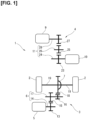
- Figure 1 is an explanatory diagram schematically illustrating an outline of the drive system of a hybrid vehicle 1 to which the present invention is applied.
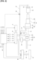
- Figure 2 is an explanatory diagram schematically illustrating an outline of the system configuration of an internal combustion engine 10 mounted in the hybrid vehicle 1 in a first embodiment of the present invention.
- the hybrid vehicle 1 has a drive unit 3 that drives drive wheels 2 and a power generation unit 4 that generates electric power for driving the drive wheels 2.
- the drive unit 3 has a drive motor 5 that rotationally drives the drive wheels 2, and a first gear train 6 and a differential gear 7 that transmit the driving force of the drive motor 5 to the drive wheels 2.
- the drive motor 5 is supplied with electric power from a not-shown battery charged by the power generated by the power generation unit 4.
- the power generation unit 4 has a generator 9 that can act as an electric motor that generates the power to be supplied to the drive motor 5, the internal combustion engine 10 that drives the generator 9, and a second gear train 11 that transmits the rotation of the internal combustion engine 10 to the generator 9.
- the hybrid vehicle 1 according to the present embodiment is a so-called series hybrid vehicle that does not use the internal combustion engine 10 to power the vehicle. That is, in the hybrid vehicle 1 according to the present embodiment, the internal combustion engine 10 is dedicated to power generation, and the drive motor 5 drives the drive wheels 2 to run the vehicle. That is, the hybrid vehicle 1 according to the present embodiment can drive the drive wheels 2 even if the internal combustion engine 10 is stopped. For example, in the hybrid vehicle 1 according to the present embodiment, when the remaining battery capacity (remaining charge) of the battery is low, the internal combustion engine 10 is driven and the generator 9 generates power in order to charge the battery.
- the drive motor 5 acts as a direct drive source for the vehicle, and is driven by AC power from the battery.
- the drive motor 5 can be a synchronous motor with a permanent magnet rotor.
- the drive motor 5 functions as a generator when the vehicle decelerates. That is, the drive motor 5 is a power generation motor that can charge the battery using the regenerative energy as electric power when the vehicle decelerates.
- the first gear train 6 is for decelerating the rotation of the drive motor 5 and increasing the motor torque to secure the travel drive torque.
- the first gear train 6 is, for example, a gear train with two-stage deceleration, and includes a motor shaft 14 equipped with a drive unit first gear 13, and a first idler shaft 17 equipped with a drive unit second gear 15 and a drive unit third gear 16.
- the motor shaft 14 is a rotary shaft of the drive motor 5.
- the drive unit first gear 13 engages with the drive unit second gear 15.
- the drive unit third gear 16 engages with an input-side gear 18 provided on the input side of the differential gear 7.
- the differential gear 7 transmits the drive torque input from the first gear train 6 via the input-side gear 18 to the left and right drive wheels 2, 2 via left and right drive shafts 19, 19.
- the differential gear 7 can transmit the same drive torque to the left and right drive wheels 2, 2 while allowing a difference in the rotational speeds of the left and right drive wheels 2, 2.
- the generator 9 comprises a synchronous motor with a permanent magnet rotor.
- the generator 9 converts the rotational energy generated by the internal combustion engine 10 into electrical energy and, for example, charges the battery described above.
- the generator 9 functions as an electric motor that rotates the internal combustion engine 10, and functions as a starter motor when the internal combustion engine 10 is started. That is, the generator 9 acts as a power generation motor that can supply the generated electric power to the battery and that can be rotationally driven by means of the electric power from the battery.
- the electric power generated by the generator 9 may be, for example, directly supplied to the drive motor 5 instead of charging the above-described battery in accordance with the driving state.
- the internal combustion engine 10 may be configured to be started by a dedicated starter motor that is not the generator 9.
- the second gear train 11 is a gear train that connects the internal combustion engine 10 and the generator 9. That is, the internal combustion engine 10 and the generator 9 are mechanically connected.
- the second gear train 11 has an engine shaft 24 equipped with a power generation unit first gear 23, a second idler shaft 26 equipped with a power generation unit second gear 25, and a generator input shaft 28 equipped with a power generation unit third gear 27.
- the second gear train 11 increases the rotational speed of the internal combustion engine 10 to transmit the required engine torque to the generator 9.
- the second gear train 11 reduces the rotational speed of the generator 9 to transmit the required motor torque to the internal combustion engine 10.
- the engine shaft 24 rotates synchronously with a crankshaft (not shown) of the internal combustion engine 10.
- the generator input shaft 28 rotates synchronously with a rotor (not shown) of the generator 9.
- the power generation unit first gear 23 engages with the power generation unit second gear 25.
- the power generation unit third gear 27 engages with the power generation unit second gear 25. That is, the power generation unit first gear 23 and the power generation unit third gear 27 engage with the power generation unit second gear 25.
- Figure 2 is an explanatory diagram schematically illustrating the system configuration of the internal combustion engine 10 of the first embodiment.
- the internal combustion engine 10 is a so-called reciprocating internal combustion engine, which converts the reciprocating linear motion of the pistons (not shown) into the rotary motion of a crankshaft (now shown) and extracts it as power.
- the generator 9 is connected to the internal combustion engine 10. The generator 9 thus generates electrical power by rotating the internal combustion engine 10.
- the internal combustion engine 10 has an intake passage 31 and an exhaust passage 32.
- An electric throttle valve 34 the degree of opening of which is controlled by a control signal from a control unit 33, is provided in the intake passage 31.
- the throttle valve 34 controls the amount of intake air.
- a purge passage 36 for introducing the evaporative fuel generated in a fuel tank 35 is connected to the intake passage 31.
- the purge passage 36 is connected to the intake passage 31 downstream of the throttle valve 34.
- the purge passage 36 is provided with a purge control valve 37 and a canister 38.
- the canister 38 adsorbs the evaporative fuel generated in the fuel tank 35.
- the purge control valve 37 is disposed downstream of the canister 38.
- An upstream side exhaust catalyst device 41, and a downstream side exhaust catalyst device 42 positioned downstream of the upstream side exhaust catalyst device 41 are provided in the exhaust passage 32.
- the upstream side exhaust catalyst device 41 and the downstream side exhaust catalyst device 42 are exhaust purification catalytic converters.
- the upstream side exhaust catalyst device 41 comprises a first catalytic converter 43, a second catalytic converter 44, which is a three-way catalytic converter, and a third catalytic converter 45, which is an NOx trap catalytic converter that are series-connected.
- the second catalytic converter 44 is positioned downstream of the first catalytic converter 43.
- the third catalytic converter 45 is positioned downstream of the second catalytic converter 44.
- the first catalytic converter 43 comprises a fourth catalytic converter 46, which is an electric heating catalytic converter, and a fifth catalytic converter 47, which is an NOx trap catalytic converter that are series-connected.
- the fourth catalytic converter 46 is positioned upstream of the fifth catalytic converter 47.
- the first catalytic converter 43 may be a series-connected electric heating catalytic converter and a three-way catalytic converter. In this case, the electric heating catalytic converter is positioned upstream of the three-way catalytic converter.
- the electric heating generates heat when energized.
- the energization of the fourth catalytic converter 46 which is an electric heating catalytic converter, is controlled by the control unit 33.
- the NOx trap catalytic converter traps NOx (nitrogen oxides) in the exhaust when the exhaust air-fuel ratio is lean, and reduces and purifies the trapped NOx when the exhaust air-fuel ratio is at or below the theoretical value, using the HC (hydrocarbons) and CO in the exhaust as reducing agents.
- the three-way catalytic converter can simultaneously purify the NOx, HC, and CO in the exhaust with maximum conversion efficiency when the air-fuel ratio is within a so-called window centered at the theoretical air-fuel ratio.
- An A/F sensor 51 is disposed upstream to the upstream side exhaust catalyst device 41.
- the A/F sensor 51 is a so-called wide range air-fuel ratio sensor that has a substantially linear output characteristic with respect to the exhaust air-fuel ratio.
- the downstream side exhaust catalyst device 42 is a so-called underfloor catalytic converter located for instance beneath the floor of the vehicle, and comprises a three-way catalytic converter, for example.
- An oxygen sensor 52 and an NOx sensor 53 are disposed downstream of the downstream side exhaust catalyst device 42.
- the oxygen sensor 52 detects only rich or lean air-fuel ratios by changing the output voltage ON/OFF (rich, lean) over a narrow range near the theoretical air-fuel ratio.
- the NOx sensor 53 is a sensor for detecting NOx concentrations.
- the internal combustion engine 10 has a turbocharger 55 serving as a supercharger.
- the turbocharger 55 includes a compressor 56 provided coaxially with the intake passage 31 and an exhaust turbine 57 provided coaxially with the exhaust passage 32.
- the turbocharger 55 has an electric motor 58 serving as a supercharger electric motor that can rotationally drive the compressor 56.
- the compressor 56 is disposed upstream of the throttle valve 34.
- the compressor 56 is disposed downstream of an air flow meter, not shown.
- the exhaust turbine 57 is disposed upstream of the upstream side exhaust catalyst device 41.
- the compressor 56 can be driven by the exhaust turbine 57 and the electric motor 58.
- An exhaust bypass passage 61 that bypasses the exhaust turbine 57 and connects the upstream side and the downstream side of the exhaust turbine 57 is connected to the exhaust passage 32.
- the downstream end of the exhaust bypass passage 61 is connected to the exhaust passage 32 in a location upstream of the upstream side exhaust catalyst device 41.
- An electric waste gate valve 62 that controls the exhaust flow rate in the exhaust bypass passage 61 is disposed in the exhaust bypass passage 61.
- the waste gate valve 62 can bypass a portion of the exhaust gas that is guided to the exhaust turbine 57 to the downstream side of the exhaust turbine 57 and can control the supercharging pressure of the internal combustion engine 10.
- a supercharger that can be applied to the present invention is not limited to a so-called electric turbocharger that can rotate the compressor 56 with the electric motor 58, such as the above-described turbocharger 55.
- a turbocharger 55 from which the electric motor 58 has been omitted, or a mechanical turbocharger (supercharger) in which a compressor disposed in the intake passage 31 is driven by the internal combustion engine 10 may be applied to the present invention.
- the control unit 33 is a known digital computer provided with a CPU, ROM, RAM, and an input/output interface.
- detection signals of various sensors such as an EVAP pressure sensor 63 for detecting the internal pressure of the canister 38, a crank angle sensor 64 for detecting the crank angle of the crankshaft, and the like, are input to the control unit 33.
- the crank angle sensor 64 can detect the engine rotational speed of the internal combustion engine 10.
- control unit 33 drives the internal combustion engine 10 to generate power with the generator 9.
- the control unit 33 controls the opening degrees of the throttle valve 34, the purge control valve 37, and the waste gate valve 62.
- the control unit 33 controls the operation of the electric motor 58 of the turbocharger 55.
- control unit 33 drives the internal combustion engine 10 to generate power with the generator 9.
- the control unit 33 can estimate the amount of evaporative fuel adsorbed in the canister 38 using the detected value of the EVAP pressure sensor 63. That is, the control unit 33 corresponds to an evaporative fuel amount detection unit for detecting the state of generation of evaporative fuel.
- the control unit 33 can use the detected values of the oxygen sensor 52 and the NOx sensor 53 to estimate the amount of HC on the downstream side of the downstream side exhaust catalyst device 42. That is, the control unit 33 corresponds to an HC detection unit for detecting the amount of HC on the downstream side of the downstream side exhaust catalyst device 42.
- the internal combustion engine 10 is not operated when power generation by the generator 9 is not required. That is, in the internal combustion engine 10 there are few opportunities to open the purge control valve 37 to purge the evaporative fuel adsorbed in the canister 38 for the introduction thereof into the intake passage 31. Thus, there is the risk of the forced purging of the evaporative fuel in the canister 38 and the introduction thereof into the intake passage 31 during the operation of the internal combustion engine 10.
- the internal combustion engine 10 Since the internal combustion engine 10 is used exclusively for power generation, an operating region that leads to a deterioration in fuel consumption is not used during power generation, and the internal combustion engine is operated at an air-fuel ratio that is leaner than the theoretical air-fuel ratio from the standpoint of enhancing fuel consumption.
- the control unit 33 corresponds to a first control unit that causes the generator 9 to rotate (idle) the internal combustion engine 10, when the internal combustion engine 10 is stopped during operation of the hybrid vehicle 1 and a prescribed set of conditions is satisfied.
- the prescribed set of conditions for rotating the internal combustion engine 10 with the generator 9 may include, for example, the case in which the amount of evaporative fuel adsorbed in the canister 38 is greater than or equal to a prescribed amount, which has been set in advance.
- the hybrid vehicle 1 purges the evaporative fuel adsorbed in the canister 38, the evaporative fuel is introduced into the intake passage 31 via the purge passage 36, and the introduced evaporative fuel is adsorbed in the upstream side exhaust catalyst device 41 and the downstream side exhaust catalyst device 42 as a reducing agent.
- control unit 33 corresponds to a second control unit that introduces the evaporative fuel adsorbed in the canister 38 upstream to the upstream side exhaust catalyst device 41, serving as an exhaust purification catalytic converter provided in the exhaust passage 32 of the internal combustion engine 10, when the internal combustion engine 10 is driven the generator 9 in motor mode, and causes the introduced evaporative fuel to be adsorbed in the upstream side exhaust catalyst device 41 and the downstream side exhaust catalyst device 42 as a reducing agent.
- the hybrid vehicle 1 has the canister 38 that adsorbs the evaporative fuel generated in the fuel tank 35 of the internal combustion engine 10 that can be operated at an air-fuel ratio that is leaner than the theoretical air-fuel ratio, and can drive the drive wheels 2 even when the internal combustion engine 10 is stopped.
- the internal combustion engine 10 when a prescribed set of conditions is satisfied when the internal combustion engine 10 is stopped during vehicle operation, the internal combustion engine 10 is rotated by the generator 9, the evaporative fuel adsorbed in the canister 38 is introduced upstream to the upstream side exhaust catalyst device 41, which is an exhaust purification catalytic converter provided in the exhaust passage 32 of the internal combustion engine 10, via the purge passage 36, and the introduced evaporative fuel is adsorbed in the upstream side exhaust catalyst device 41 and the downstream side exhaust catalyst device 42 as a reducing agent.
- the upstream side exhaust catalyst device 41 which is an exhaust purification catalytic converter provided in the exhaust passage 32 of the internal combustion engine 10
- the engine rotational speed of the internal combustion engine 10 is controlled to be a prescribed rotational speed set in advance.
- This prescribed rotational speed is a rotational speed at which the introduced evaporative fuel is not discharged to the outside air from the downstream side of the downstream side exhaust catalyst device 42.
- the prescribed rotational speed is a value that is lower than the engine rotational speed when the internal combustion engine 10 is driven by the generator 9 to generate power.
- the above-described prescribed rotational speed is a value that is below the engine rotational speed during power generation mode when the generator 9 is driven by the internal combustion engine 10.
- the evaporative fuel is not discharged to the outside even when the evaporative fuel is introduced upstream to the upstream side exhaust catalyst device 41 when the internal combustion engine 10 is rotated by the generator 9, so that it is possible to suppress a deterioration in exhaust performance.
- the opening degree of the throttle valve 34 is adjusted to generate a negative pressure downstream of the throttle valve 34, and the purge control valve 37 is opened.
- the purge control valve 37 is controlled such that the opening degree increases as the amount of evaporative fuel adsorbed in the canister 38 increases.
- the opening degree of the purge control valve 37 when the evaporative fuel is introduced into the intake passage 31 may be controlled such that the introduced evaporative fuel is not discharged to the outside air from the downstream side of the downstream side exhaust catalyst device 42.
- the hybrid vehicle 1 to supply the evaporative fuel as a reducing agent to the upstream side exhaust catalyst device 41 and the downstream side exhaust catalyst device 42 before the internal combustion engine 10 starts up.
- the hybrid vehicle 1 is able to suppress a deterioration in combustion stability and exhaust performance of the internal combustion engine 10 caused by the evaporative fuel introduced by means of purging, and to secure exhaust gas purification performance of the upstream side exhaust catalyst device 41 and the downstream side exhaust catalyst device 42 when the internal combustion engine 10 starts (self-sustaining operation).
- a self-sustaining operation of the internal combustion engine 10 refers to an operating state in which fuel is combusted to generate driving force.
- the hybrid vehicle 1 the evaporative fuel is supplied to the upstream side exhaust catalyst device 41 and the downstream side exhaust catalyst device 42 while the internal combustion engine 10 is stopped.
- the hybrid vehicle 1 is able to improve the NOx purification performance of the upstream side exhaust catalyst device 41 and the downstream side exhaust catalyst device 42 at the time of starting of the internal combustion engine 10.
- the hybrid vehicle 1 since the evaporative fuel is introduced into the intake passage 31 while the internal combustion engine 10 is stopped, it is unlikely that the evaporative fuel will be introduced into the intake passage 31 during lean operation of the internal combustion engine 10. Therefore, in the hybrid vehicle 1, since there is little variation in the amount of evaporative fuel introduced and in the air-fuel ratio, the margin when the air-fuel ratio is set can be relatively narrow, and it is possible to suppress a deterioration in fuel consumption and exhaust performance.
- Mode fuel consumption is the amount of fuel consumed (fuel consumption) when the vehicle is operated in accordance with a prescribed set of conditions.
- a bypass passage 67 that bypasses the internal combustion engine 10 and that connects the intake passage 31 and the exhaust passage 32 is provided, as shown by the broken line in Figure 2 .
- the bypass passage 67 is, for example, connected to the intake passage 31 on the downstream side of the throttle valve 34 and connected to the exhaust passage 32 on the downstream side of the downstream side exhaust catalyst device 42.
- a bypass valve 68 is provided in the bypass passage 67.
- the bypass valve 68 is opened if the evaporative fuel is detected downstream of the downstream side exhaust catalyst device 42, when the evaporative fuel is introduced.
- the opening degree of the bypass valve 68 is controlled by the control unit 33.
- Figure 3 is a flowchart showing one example of a control flow of the hybrid vehicle 1 in the first embodiment described above, not according to the claimed invention.
- Step S11 the internal pressure of the canister 38 is detected.
- Step S12 it is determined whether the internal combustion engine 10 is stopped. If it is determined in Step S12 that the internal combustion engine 10 is stopped, the process proceeds to Step S13. If it is determined in Step S12 that the internal combustion engine 10 is not stopped, the current routine is ended.
- Step S13 the amount of evaporative fuel adsorbed in the canister 38 is estimated from the internal pressure of the canister 38, and it is determined that there is a request for purging the canister 38 when the amount of evaporative fuel is greater than or equal to a prescribed amount set in advance. If there is a purge processing request in Step S13, the process proceeds to Step S14.
- Step S13 If there is no purge processing request in Step S13, the current routine is ended.
- Step S14 the generator 9 rotates the internal combustion engine 10.
- Step S15 the purge control valve 37 is opened.
- Step S16 the opening degree of the purge control valve 37 is controlled such that the opening degree increases as the amount of evaporative fuel inside the canister 38 increases.
- the opening degree of the purge control valve 37 and the engine rotational speed of the internal combustion engine 10 are controlled such that the introduced evaporative fuel is not discharged to the outside air from the downstream side of the downstream side exhaust catalyst device 42 as in the first embodiment described above. Accordingly, the system configuration of the internal combustion engine 10 in the second embodiment is the same as that of the first embodiment described above.
- Figure 4 is a flowchart showing one example of the control flow of the hybrid vehicle 1 of the second embodiment.
- Step S21 the internal pressure of the canister 38 is detected.
- Step S22 it is determined whether the internal combustion engine 10 is stopped. If it is determined in Step S22 that the internal combustion engine 10 is stopped, the process proceeds to Step S23. If it is determined in Step S22 that the internal combustion engine 10 is not stopped, the current routine is ended.
- Step S23 the amount of evaporative fuel adsorbed in the canister 38 is estimated from the internal pressure of the canister 38, and it is determined that there is a request for purging the canister 38 when the amount of evaporative fuel is greater than or equal to a prescribed amount set in advance. If there is a purge processing request in Step S23, the process proceeds to Step S24.
- Step S24 the generator 9 rotates the internal combustion engine 10.
- Step S25 the engine rotational speed of the internal combustion engine 10 when rotated by the generator 9 is controlled such that the introduced evaporative fuel is not discharged to the outside air from the downstream side of the downstream side exhaust catalyst device 42.
- Step S26 the purge control valve 37 is opened.
- Step S27 the opening degree of the purge control valve 37 is controlled such that the introduced evaporative fuel is not discharged to the outside air from the downstream side of the downstream side exhaust catalyst device 42.
- either the engine rotational speed of the internal combustion engine 10 or the opening degree of the purge control valve 37 may be controlled such that the evaporative fuel is not discharged to the outside air from the downstream side of the downstream side exhaust catalyst device 42. That is, either Step S23 or Step S26 may be omitted from the flowchart shown in Figure 4 .
- the fourth catalytic converter 46 which is an electric heating catalytic converter, is energized when introducing the evaporative fuel, in the first embodiment described above. Accordingly, the system configuration of the internal combustion engine 10 in the third embodiment is the same as that of the first embodiment described above.
- Figure 5 is a flowchart showing one example of a control flow of the hybrid vehicle 1 in the third embodiment.
- Step S31 the internal pressure of the canister 38 is detected.
- Step S32 it is determined whether the internal combustion engine 10 is stopped. If it is determined in Step S32 that the internal combustion engine 10 is stopped, the process proceeds to Step S33. If it is determined in Step S32 that the internal combustion engine 10 is not stopped, the current routine is ended.
- Step S33 the amount of evaporative fuel adsorbed in the canister 38 is estimated from the internal pressure of the canister 38, and it is determined that there is a request for purging the canister 38 when the amount of evaporative fuel is greater than or equal to a prescribed amount set in advance. If there is a purge processing request in Step S33, the process proceeds to Step S34.
- Step S34 the generator 9 rotates the internal combustion engine 10.
- Step S35 the purge control valve 37 is opened.
- Step S36 the opening degree of the purge control valve 37 is controlled such that the opening degree increases as the amount of evaporative fuel inside the canister 38 increases.
- Step S37 the fourth catalytic converter 46, which is an electric heating catalytic converter, is energized.
- the fourth catalytic converter 46 which is an electric heating catalytic converter
- the fifth catalytic converter 47 which is an NOx trap catalytic converter
- the fifth catalytic converter 47 constituting the first catalytic converter 43 is a three-way catalytic converter, by energizing the fourth catalytic converter 46, which is an electric heating catalytic converter, to preheat the fourth catalytic converter 46, it is possible to activate the fifth catalytic converter 47, which is a three-way catalytic converter, in order to purify the NOx with the introduced evaporative fuel.
- bypass passage 67 and the bypass valve 68 are provided in the first embodiment described above. Accordingly, the system configuration of the internal combustion engine 10 in the fourth embodiment is the same as that of the first embodiment described above.
- evaporative fuel that did not adhere to the upstream side exhaust catalyst device 41 and the downstream side exhaust catalyst device 42 is returned to the intake passage 31 via the bypass passage 67 such that the evaporative fuel is not discharged to the outside.
- the evaporative fuel that has flowed out to the downstream side of the downstream side exhaust catalyst device 42 can be returned to the intake passage 31 by controlling the opening degree of the throttle valve 34 to generate a negative pressure on the downstream side of the throttle valve 34.
- Figure 6 is a flowchart showing one example of the control flow of the hybrid vehicle 1 of the fourth embodiment.
- Step S41 the internal pressure of the canister 38 is detected.
- Step S42 it is determined whether the internal combustion engine 10 is stopped. If it is determined in Step S42 that the internal combustion engine 10 is stopped, the process proceeds to Step S43. If it is determined in Step S42 that the internal combustion engine 10 is not stopped, the current routine is ended.
- Step S43 the amount of evaporative fuel adsorbed in the canister 38 is estimated from the internal pressure of the canister 38, and it is determined that there is a request for purging the canister 38 when the amount of evaporative fuel is greater than or equal to a prescribed amount set in advance. If there is a purge processing request in Step S43, the process proceeds to Step S44.
- Step S44 the generator 9 rotates the internal combustion engine 10.
- Step S45 the purge control valve 37 is opened.
- Step S46 the opening degree of the purge control valve 37 is controlled such that the opening degree increases as the amount of evaporative fuel inside the canister 38 increases.
- Step S47 the amount of HC downstream of the downstream side exhaust catalyst device 42 is detected.
- Step S48 the opening degree of the bypass valve 68 is controlled in accordance with the amount of HC downstream of the downstream side exhaust catalyst device 42. For example, if HC is not detected downstream of the downstream side exhaust catalyst device 42, the bypass valve 68 is closed. In addition, if HC is detected downstream of the downstream side exhaust catalyst device 42, the opening degree of the bypass valve 68 is increased proportionally with the amount of detected increase of the HC.
- the evaporative fuel that was not adsorbed by the upstream side exhaust catalyst device 41 and the downstream side exhaust catalyst device 42 is returned to the intake passage 31, so that it is possible to suppress the discharge of the introduced evaporative fuel from the exhaust passage 32 to the outside.
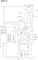
- Figure 7 is an explanatory diagram schematically illustrating the system configuration of the internal combustion engine 10 of the fifth embodiment.
- the fifth embodiment has essentially the same configuration as the first embodiment described above, but the purge passage 36 is connected to the intake passage 31 on the upstream side of the compressor 56.
- the electric motor 58 is used to rotate the compressor 56 to generate a negative pressure upstream to the compressor 56, and the purge control valve 37 is opened.
- the internal combustion engine 10 when the internal combustion engine 10 is stopped during operation of the vehicle, the internal combustion engine 10 can be idled by the generator 9, and the evaporative fuel adsorbed in the canister 38 can be introduced upstream to the upstream side exhaust catalyst device 41, which is an exhaust purification catalytic converter provided in the exhaust passage 32 of the internal combustion engine 10, via the purge passage 36.
- the introduced evaporative fuel can be adsorbed in the upstream side exhaust catalyst device 41 and the downstream side exhaust catalyst device 42 as a reducing agent.
- a bypass passage 69 that bypasses the internal combustion engine 10 and that connects the intake passage 31 and the exhaust passage 32 may be provided, as indicated by the broken line in Figure 7 .
- the bypass passage 69 is, for example, connected to the intake passage 31 on the upstream side of the compressor 56 and connected to the exhaust passage 32 on the downstream side of the downstream side exhaust catalyst device 42.
- a bypass valve 70 is provided in the bypass passage 69.
- the bypass valve 70 is opened if the evaporative fuel is detected downstream of the downstream side exhaust catalyst device 42, when the evaporative fuel is introduced.
- the opening degree of the bypass valve 70 is controlled by the control unit 33.
- a second throttle valve 71 serving as a control valve may be provided upstream of the connection position between the purge passage 36 and the intake passage 31, or the connection position between the bypass passage 67 and the intake passage 31.
- the bypass passage 69 By using the bypass passage 69, the evaporative fuel that did not adhere to the upstream side exhaust catalyst device 41 and the downstream side exhaust catalyst device 42 can be returned to the intake passage 31 such that the evaporative fuel is not discharged to the outside.
- the evaporative fuel that has flowed out to the downstream side of the downstream side exhaust catalyst device 42 can be returned to the intake passage 31 by rotating the compressor 56 with the electric motor 58, for example, to generate a negative pressure on the upstream side of the compressor 56.
- the rotation of the electric motor 58 is controlled by the control unit 33.
- the evaporative fuel that has flowed out to the downstream side of the downstream side exhaust catalyst device 42 can also be returned to the intake passage 31 by controlling the opening degree of the second throttle valve 71 to generate a negative pressure on the downstream side of the second throttle valve 71.
- the opening degree of the second throttle valve 71 may be controlled by the control unit 33.
- the bypass passage 69 by using the bypass passage 69, the evaporative fuel that was not adsorbed by the upstream side exhaust catalyst device 41 and the downstream side exhaust catalyst device 42 can be returned to the intake passage 31, so that it is possible to suppress the discharge of the introduced evaporative fuel from the exhaust passage 32 to the outside.
- an EGR passage may be used as the bypass passages 67, 69. That is, the bypass passages 67, 69 may be EGR passages that recirculate a portion of the exhaust of the internal combustion engine 10 to the intake passage 31.
- an EGR control valve that is provided in the EGR passage and controls the amount of exhaust recirculation corresponds to the bypass valves 67, 68.
- the present invention can be applied to a hybrid vehicle other than the above-described series hybrid vehicle (for example, to a so-called parallel hybrid vehicle).
- the present invention can be applied to a hybrid vehicle that can drive the drive wheels 2 for vehicle travel even if the internal combustion engine 10 is stopped.
- the above-described embodiments relate to the hybrid vehicle control method and hybrid vehicle control device.
Landscapes
- Engineering & Computer Science (AREA)
- Chemical & Material Sciences (AREA)
- Combustion & Propulsion (AREA)
- Mechanical Engineering (AREA)
- General Engineering & Computer Science (AREA)
- Chemical Kinetics & Catalysis (AREA)
- Transportation (AREA)
- Toxicology (AREA)
- Health & Medical Sciences (AREA)
- Automation & Control Theory (AREA)
- Materials Engineering (AREA)
- Supplying Secondary Fuel Or The Like To Fuel, Air Or Fuel-Air Mixtures (AREA)
- Hybrid Electric Vehicles (AREA)
- Exhaust Gas After Treatment (AREA)
- Container, Conveyance, Adherence, Positioning, Of Wafer (AREA)
- Testing Or Measuring Of Semiconductors Or The Like (AREA)
Applications Claiming Priority (1)
| Application Number | Priority Date | Filing Date | Title |
|---|---|---|---|
| PCT/IB2019/000429 WO2020212719A1 (ja) | 2019-04-19 | 2019-04-19 | ハイブリッド車両の制御方法及びハイブリッド車両の制御装置 |
Publications (3)
| Publication Number | Publication Date |
|---|---|
| EP3957530A1 EP3957530A1 (en) | 2022-02-23 |
| EP3957530A4 EP3957530A4 (en) | 2022-05-11 |
| EP3957530B1 true EP3957530B1 (en) | 2024-04-17 |
Family
ID=72836770
Family Applications (1)
| Application Number | Title | Priority Date | Filing Date |
|---|---|---|---|
| EP19924644.8A Active EP3957530B1 (en) | 2019-04-19 | 2019-04-19 | Hybrid vehicle control method and hybrid vehicle control device |
Country Status (5)
| Country | Link |
|---|---|
| US (1) | US11708806B2 (https=) |
| EP (1) | EP3957530B1 (https=) |
| JP (1) | JP7105414B2 (https=) |
| CN (1) | CN113710555B (https=) |
| WO (1) | WO2020212719A1 (https=) |
Families Citing this family (2)
| Publication number | Priority date | Publication date | Assignee | Title |
|---|---|---|---|---|
| JP7190048B2 (ja) * | 2019-08-02 | 2022-12-14 | 日産自動車株式会社 | 内燃機関の制御方法及び内燃機関の制御装置 |
| WO2022024373A1 (ja) * | 2020-07-31 | 2022-02-03 | 日産自動車株式会社 | シリーズハイブリッド車両の制御方法及びシリーズハイブリッド車両 |
Family Cites Families (29)
| Publication number | Priority date | Publication date | Assignee | Title |
|---|---|---|---|---|
| JPH04252852A (ja) | 1991-01-29 | 1992-09-08 | Toyota Motor Corp | 過給機付エンジンの蒸発燃料制御装置 |
| JP2932828B2 (ja) | 1992-05-11 | 1999-08-09 | 日産自動車株式会社 | ディーゼル機関の排気制御装置 |
| JP3175572B2 (ja) * | 1995-12-28 | 2001-06-11 | トヨタ自動車株式会社 | 車両用制御装置 |
| JP3257402B2 (ja) * | 1996-06-14 | 2002-02-18 | 日産自動車株式会社 | ハイブリッド電気自動車の発電機駆動用エンジンの制御装置 |
| JP3336912B2 (ja) * | 1997-06-25 | 2002-10-21 | トヨタ自動車株式会社 | エンジンの蒸発燃料パージ装置 |
| JP4207295B2 (ja) | 1999-03-05 | 2009-01-14 | マツダ株式会社 | 筒内噴射式エンジンの制御装置 |
| JP3575323B2 (ja) * | 1999-03-31 | 2004-10-13 | マツダ株式会社 | ハイブリッド自動車のエンジン制御装置 |
| JP4231958B2 (ja) | 1999-03-31 | 2009-03-04 | マツダ株式会社 | エンジンの制御装置 |
| JP2004019519A (ja) * | 2002-06-14 | 2004-01-22 | Toyota Motor Corp | エンジンシステムの制御装置 |
| JP4243991B2 (ja) * | 2003-07-11 | 2009-03-25 | 株式会社デンソー | 内燃機関の炭化水素排出量低減装置 |
| JP3700715B2 (ja) * | 2003-08-12 | 2005-09-28 | トヨタ自動車株式会社 | 内燃機関の制御装置 |
| JP2009083541A (ja) * | 2007-09-27 | 2009-04-23 | Toyota Motor Corp | ハイブリッド車両の制御装置 |
| JP5453737B2 (ja) * | 2008-06-03 | 2014-03-26 | マツダ株式会社 | 排気ガス浄化方法及び排気ガス浄化装置 |
| JP5071889B2 (ja) * | 2008-07-02 | 2012-11-14 | マツダ株式会社 | デュアルフューエルエンジンの制御方法及びその装置 |
| JP2011031832A (ja) * | 2009-08-05 | 2011-02-17 | Nissan Motor Co Ltd | ハイブリッド車両用内燃機関の制御装置 |
| JP2011252466A (ja) * | 2010-06-04 | 2011-12-15 | Hitachi Automotive Systems Ltd | 内燃機関のアイドルストップ時のパージ装置 |
| JP2012225231A (ja) * | 2011-04-19 | 2012-11-15 | Denso Corp | 燃料蒸発ガス処理装置 |
| US8739766B2 (en) * | 2011-08-04 | 2014-06-03 | Ford Global Technologies, Llc | Method and system for fuel vapor control |
| EP2806141B1 (en) * | 2012-01-19 | 2019-03-13 | Nissan Motor Co., Ltd | Engine control device and control method for hybrid drive vehicle |
| JP2013184621A (ja) * | 2012-03-09 | 2013-09-19 | Nissan Motor Co Ltd | ハイブリッド車両の蒸発燃料処理装置 |
| JP2014015876A (ja) | 2012-07-06 | 2014-01-30 | Toyota Motor Corp | 過給機付き内燃機関の制御装置 |
| US10087896B1 (en) * | 2012-10-14 | 2018-10-02 | Alberto Martin Perez | Liquefied light hydrocarbon fuel system for hybrid vehicle and methods thereto |
| US9656666B2 (en) * | 2014-08-28 | 2017-05-23 | Ford Global Technologies, Llc | Methods and systems for starting an engine |
| JP6476839B2 (ja) * | 2014-12-24 | 2019-03-06 | 日産自動車株式会社 | 車両の制御装置 |
| US9937786B2 (en) | 2015-06-22 | 2018-04-10 | Ford Global Technologies, Llc | Fuel tank baffle with pivotable vanes |
| CN106627090B (zh) * | 2016-12-15 | 2019-03-08 | 石家庄新华能源环保科技股份有限公司 | 可以回收余热和净化环境空气的氢能源汽车混合动力系统 |
| JP6819283B2 (ja) * | 2016-12-28 | 2021-01-27 | 三菱自動車工業株式会社 | 排気浄化装置 |
| JP2018154142A (ja) * | 2017-03-15 | 2018-10-04 | トヨタ自動車株式会社 | ハイブリッド自動車 |
| US10815937B2 (en) * | 2017-10-06 | 2020-10-27 | Ford Global Technologies, Llc | Evaporative emissions system diagnostic for GTDI engines using an electronic booster |
-
2019
- 2019-04-19 CN CN201980095566.8A patent/CN113710555B/zh active Active
- 2019-04-19 WO PCT/IB2019/000429 patent/WO2020212719A1/ja not_active Ceased
- 2019-04-19 JP JP2021514496A patent/JP7105414B2/ja active Active
- 2019-04-19 EP EP19924644.8A patent/EP3957530B1/en active Active
- 2019-04-19 US US17/604,456 patent/US11708806B2/en active Active
Also Published As
| Publication number | Publication date |
|---|---|
| JPWO2020212719A1 (https=) | 2020-10-22 |
| WO2020212719A1 (ja) | 2020-10-22 |
| CN113710555A (zh) | 2021-11-26 |
| US11708806B2 (en) | 2023-07-25 |
| EP3957530A4 (en) | 2022-05-11 |
| CN113710555B (zh) | 2024-08-06 |
| EP3957530A1 (en) | 2022-02-23 |
| JP7105414B2 (ja) | 2022-07-25 |
| US20220213851A1 (en) | 2022-07-07 |
Similar Documents
| Publication | Publication Date | Title |
|---|---|---|
| JP3721088B2 (ja) | ハイブリッド車両の制御装置 | |
| US8555615B2 (en) | Internal combustion engine exhaust gas control system and control method of internal combustion engine exhaust gas control system | |
| US10967866B2 (en) | Power-train controlling apparatus and method of controlling power train | |
| JP5899104B2 (ja) | 車両の制御装置 | |
| CN111749768B (zh) | 混合动力车辆 | |
| JP4277933B1 (ja) | 内燃機関装置およびその制御方法並びに車両 | |
| CN104136728A (zh) | 内燃机的排气控制装置 | |
| JP4238910B2 (ja) | 内燃機関装置およびその制御方法並びに車両 | |
| EP3957530B1 (en) | Hybrid vehicle control method and hybrid vehicle control device | |
| CN111749767B (zh) | 混合动力车辆 | |
| JP4086005B2 (ja) | ディーゼルハイブリッド車両における低圧縮比エンジンの暖機制御方法 | |
| CN105636846A (zh) | 混合动力车辆的控制装置 | |
| JP4548143B2 (ja) | ハイブリッド車両の排気浄化装置 | |
| JP2003269180A (ja) | 過給圧制御装置 | |
| JP4001094B2 (ja) | ハイブリッド車両の制御装置 | |
| JP2006112311A (ja) | ハイブリッド車の排気浄化装置 | |
| CN116368045B (zh) | 车辆的控制方法以及车辆的控制装置 | |
| JP2009257223A (ja) | 内燃機関装置およびこれを備えるハイブリッド車並びに異常判定方法 | |
| JP6680097B2 (ja) | ハイブリッド車両 | |
| KR20250096726A (ko) | 하이브리드 구동 디바이스의 오염 배출물을 감소시키기 위한 방법 | |
| JP2023017145A (ja) | ハイブリッド車両の制御方法及びハイブリッド車両の制御装置 | |
| CN117377605A (zh) | 混合动力车辆的控制方法以及混合动力车辆的控制装置 | |
| JPH11173173A (ja) | ハイブリッド車のegr制御装置 | |
| JP2008286071A (ja) | 車両およびその制御方法 |
Legal Events
| Date | Code | Title | Description |
|---|---|---|---|
| STAA | Information on the status of an ep patent application or granted ep patent |
Free format text: STATUS: THE INTERNATIONAL PUBLICATION HAS BEEN MADE |
|
| PUAI | Public reference made under article 153(3) epc to a published international application that has entered the european phase |
Free format text: ORIGINAL CODE: 0009012 |
|
| STAA | Information on the status of an ep patent application or granted ep patent |
Free format text: STATUS: REQUEST FOR EXAMINATION WAS MADE |
|
| 17P | Request for examination filed |
Effective date: 20211116 |
|
| AK | Designated contracting states |
Kind code of ref document: A1 Designated state(s): AL AT BE BG CH CY CZ DE DK EE ES FI FR GB GR HR HU IE IS IT LI LT LU LV MC MK MT NL NO PL PT RO RS SE SI SK SM TR |
|
| RAP3 | Party data changed (applicant data changed or rights of an application transferred) |
Owner name: RENAULT S.A.S Owner name: NISSAN MOTOR CO., LTD. |
|
| A4 | Supplementary search report drawn up and despatched |
Effective date: 20220411 |
|
| RIC1 | Information provided on ipc code assigned before grant |
Ipc: F02D 41/04 20060101ALN20220405BHEP Ipc: F02D 41/02 20060101ALI20220405BHEP Ipc: F02D 41/00 20060101ALI20220405BHEP Ipc: F01N 13/00 20100101ALI20220405BHEP Ipc: F01N 3/20 20060101ALI20220405BHEP Ipc: F01N 3/10 20060101ALI20220405BHEP Ipc: F01N 3/08 20060101ALI20220405BHEP Ipc: F01N 3/025 20060101ALI20220405BHEP Ipc: B60W 10/08 20060101ALI20220405BHEP Ipc: B60W 10/06 20060101ALI20220405BHEP Ipc: B60K 6/46 20071001ALI20220405BHEP Ipc: B60K 6/24 20071001ALI20220405BHEP Ipc: B60W 20/16 20160101AFI20220405BHEP |
|
| DAV | Request for validation of the european patent (deleted) | ||
| DAX | Request for extension of the european patent (deleted) | ||
| RAP3 | Party data changed (applicant data changed or rights of an application transferred) |
Owner name: RENAULT S.A.S Owner name: NISSAN MOTOR CO., LTD. |
|
| GRAP | Despatch of communication of intention to grant a patent |
Free format text: ORIGINAL CODE: EPIDOSNIGR1 |
|
| STAA | Information on the status of an ep patent application or granted ep patent |
Free format text: STATUS: GRANT OF PATENT IS INTENDED |
|
| RIC1 | Information provided on ipc code assigned before grant |
Ipc: F02D 41/04 20060101ALN20231214BHEP Ipc: F02D 41/02 20060101ALI20231214BHEP Ipc: F02D 41/00 20060101ALI20231214BHEP Ipc: F01N 13/00 20100101ALI20231214BHEP Ipc: F01N 3/20 20060101ALI20231214BHEP Ipc: F01N 3/10 20060101ALI20231214BHEP Ipc: F01N 3/08 20060101ALI20231214BHEP Ipc: F01N 3/025 20060101ALI20231214BHEP Ipc: B60W 10/08 20060101ALI20231214BHEP Ipc: B60W 10/06 20060101ALI20231214BHEP Ipc: B60K 6/46 20071001ALI20231214BHEP Ipc: B60K 6/24 20071001ALI20231214BHEP Ipc: B60W 20/16 20160101AFI20231214BHEP |
|
| INTG | Intention to grant announced |
Effective date: 20240104 |
|
| RIC1 | Information provided on ipc code assigned before grant |
Ipc: F02D 41/04 20060101ALN20231215BHEP Ipc: F02D 41/02 20060101ALI20231215BHEP Ipc: F02D 41/00 20060101ALI20231215BHEP Ipc: F01N 13/00 20100101ALI20231215BHEP Ipc: F01N 3/20 20060101ALI20231215BHEP Ipc: F01N 3/10 20060101ALI20231215BHEP Ipc: F01N 3/08 20060101ALI20231215BHEP Ipc: F01N 3/025 20060101ALI20231215BHEP Ipc: B60W 10/08 20060101ALI20231215BHEP Ipc: B60W 10/06 20060101ALI20231215BHEP Ipc: B60K 6/46 20071001ALI20231215BHEP Ipc: B60K 6/24 20071001ALI20231215BHEP Ipc: B60W 20/16 20160101AFI20231215BHEP |
|
| GRAS | Grant fee paid |
Free format text: ORIGINAL CODE: EPIDOSNIGR3 |
|
| GRAA | (expected) grant |
Free format text: ORIGINAL CODE: 0009210 |
|
| STAA | Information on the status of an ep patent application or granted ep patent |
Free format text: STATUS: THE PATENT HAS BEEN GRANTED |
|
| REG | Reference to a national code |
Ref country code: DE Ref legal event code: R081 Ref document number: 602019050673 Country of ref document: DE Owner name: RENAULT S.A.S., FR Free format text: FORMER OWNER: NISSAN MOTOR CO., LTD., YOKOHAMA-SHI, KANAGAWA, JP Ref country code: DE Ref legal event code: R081 Ref document number: 602019050673 Country of ref document: DE Owner name: NISSAN MOTOR CO., LTD., YOKOHAMA-SHI, JP Free format text: FORMER OWNER: NISSAN MOTOR CO., LTD., YOKOHAMA-SHI, KANAGAWA, JP |
|
| AK | Designated contracting states |
Kind code of ref document: B1 Designated state(s): AL AT BE BG CH CY CZ DE DK EE ES FI FR GB GR HR HU IE IS IT LI LT LU LV MC MK MT NL NO PL PT RO RS SE SI SK SM TR |
|
| REG | Reference to a national code |
Ref country code: GB Ref legal event code: FG4D |
|
| REG | Reference to a national code |
Ref country code: CH Ref legal event code: EP |
|
| REG | Reference to a national code |
Ref country code: DE Ref legal event code: R096 Ref document number: 602019050673 Country of ref document: DE |
|
| REG | Reference to a national code |
Ref country code: IE Ref legal event code: FG4D |
|
| REG | Reference to a national code |
Ref country code: LT Ref legal event code: MG9D |
|
| REG | Reference to a national code |
Ref country code: NL Ref legal event code: MP Effective date: 20240417 |
|
| REG | Reference to a national code |
Ref country code: AT Ref legal event code: MK05 Ref document number: 1676981 Country of ref document: AT Kind code of ref document: T Effective date: 20240417 |
|
| PG25 | Lapsed in a contracting state [announced via postgrant information from national office to epo] |
Ref country code: NL Free format text: LAPSE BECAUSE OF FAILURE TO SUBMIT A TRANSLATION OF THE DESCRIPTION OR TO PAY THE FEE WITHIN THE PRESCRIBED TIME-LIMIT Effective date: 20240417 |
|
| PG25 | Lapsed in a contracting state [announced via postgrant information from national office to epo] |
Ref country code: NL Free format text: LAPSE BECAUSE OF FAILURE TO SUBMIT A TRANSLATION OF THE DESCRIPTION OR TO PAY THE FEE WITHIN THE PRESCRIBED TIME-LIMIT Effective date: 20240417 |
|
| PG25 | Lapsed in a contracting state [announced via postgrant information from national office to epo] |
Ref country code: IS Free format text: LAPSE BECAUSE OF FAILURE TO SUBMIT A TRANSLATION OF THE DESCRIPTION OR TO PAY THE FEE WITHIN THE PRESCRIBED TIME-LIMIT Effective date: 20240817 |
|
| PG25 | Lapsed in a contracting state [announced via postgrant information from national office to epo] |
Ref country code: BG Free format text: LAPSE BECAUSE OF FAILURE TO SUBMIT A TRANSLATION OF THE DESCRIPTION OR TO PAY THE FEE WITHIN THE PRESCRIBED TIME-LIMIT Effective date: 20240417 |
|
| PG25 | Lapsed in a contracting state [announced via postgrant information from national office to epo] |
Ref country code: HR Free format text: LAPSE BECAUSE OF FAILURE TO SUBMIT A TRANSLATION OF THE DESCRIPTION OR TO PAY THE FEE WITHIN THE PRESCRIBED TIME-LIMIT Effective date: 20240417 Ref country code: FI Free format text: LAPSE BECAUSE OF FAILURE TO SUBMIT A TRANSLATION OF THE DESCRIPTION OR TO PAY THE FEE WITHIN THE PRESCRIBED TIME-LIMIT Effective date: 20240417 |
|
| PG25 | Lapsed in a contracting state [announced via postgrant information from national office to epo] |
Ref country code: GR Free format text: LAPSE BECAUSE OF FAILURE TO SUBMIT A TRANSLATION OF THE DESCRIPTION OR TO PAY THE FEE WITHIN THE PRESCRIBED TIME-LIMIT Effective date: 20240718 |
|
| PG25 | Lapsed in a contracting state [announced via postgrant information from national office to epo] |
Ref country code: PT Free format text: LAPSE BECAUSE OF FAILURE TO SUBMIT A TRANSLATION OF THE DESCRIPTION OR TO PAY THE FEE WITHIN THE PRESCRIBED TIME-LIMIT Effective date: 20240819 |
|
| PG25 | Lapsed in a contracting state [announced via postgrant information from national office to epo] |
Ref country code: ES Free format text: LAPSE BECAUSE OF FAILURE TO SUBMIT A TRANSLATION OF THE DESCRIPTION OR TO PAY THE FEE WITHIN THE PRESCRIBED TIME-LIMIT Effective date: 20240417 |
|
| PG25 | Lapsed in a contracting state [announced via postgrant information from national office to epo] |
Ref country code: AT Free format text: LAPSE BECAUSE OF FAILURE TO SUBMIT A TRANSLATION OF THE DESCRIPTION OR TO PAY THE FEE WITHIN THE PRESCRIBED TIME-LIMIT Effective date: 20240417 |
|
| PG25 | Lapsed in a contracting state [announced via postgrant information from national office to epo] |
Ref country code: PL Free format text: LAPSE BECAUSE OF FAILURE TO SUBMIT A TRANSLATION OF THE DESCRIPTION OR TO PAY THE FEE WITHIN THE PRESCRIBED TIME-LIMIT Effective date: 20240417 |
|
| PG25 | Lapsed in a contracting state [announced via postgrant information from national office to epo] |
Ref country code: LV Free format text: LAPSE BECAUSE OF FAILURE TO SUBMIT A TRANSLATION OF THE DESCRIPTION OR TO PAY THE FEE WITHIN THE PRESCRIBED TIME-LIMIT Effective date: 20240417 |
|
| PG25 | Lapsed in a contracting state [announced via postgrant information from national office to epo] |
Ref country code: PT Free format text: LAPSE BECAUSE OF FAILURE TO SUBMIT A TRANSLATION OF THE DESCRIPTION OR TO PAY THE FEE WITHIN THE PRESCRIBED TIME-LIMIT Effective date: 20240819 Ref country code: PL Free format text: LAPSE BECAUSE OF FAILURE TO SUBMIT A TRANSLATION OF THE DESCRIPTION OR TO PAY THE FEE WITHIN THE PRESCRIBED TIME-LIMIT Effective date: 20240417 Ref country code: NO Free format text: LAPSE BECAUSE OF FAILURE TO SUBMIT A TRANSLATION OF THE DESCRIPTION OR TO PAY THE FEE WITHIN THE PRESCRIBED TIME-LIMIT Effective date: 20240717 Ref country code: LV Free format text: LAPSE BECAUSE OF FAILURE TO SUBMIT A TRANSLATION OF THE DESCRIPTION OR TO PAY THE FEE WITHIN THE PRESCRIBED TIME-LIMIT Effective date: 20240417 Ref country code: IS Free format text: LAPSE BECAUSE OF FAILURE TO SUBMIT A TRANSLATION OF THE DESCRIPTION OR TO PAY THE FEE WITHIN THE PRESCRIBED TIME-LIMIT Effective date: 20240817 Ref country code: HR Free format text: LAPSE BECAUSE OF FAILURE TO SUBMIT A TRANSLATION OF THE DESCRIPTION OR TO PAY THE FEE WITHIN THE PRESCRIBED TIME-LIMIT Effective date: 20240417 Ref country code: GR Free format text: LAPSE BECAUSE OF FAILURE TO SUBMIT A TRANSLATION OF THE DESCRIPTION OR TO PAY THE FEE WITHIN THE PRESCRIBED TIME-LIMIT Effective date: 20240718 Ref country code: FI Free format text: LAPSE BECAUSE OF FAILURE TO SUBMIT A TRANSLATION OF THE DESCRIPTION OR TO PAY THE FEE WITHIN THE PRESCRIBED TIME-LIMIT Effective date: 20240417 Ref country code: ES Free format text: LAPSE BECAUSE OF FAILURE TO SUBMIT A TRANSLATION OF THE DESCRIPTION OR TO PAY THE FEE WITHIN THE PRESCRIBED TIME-LIMIT Effective date: 20240417 Ref country code: BG Free format text: LAPSE BECAUSE OF FAILURE TO SUBMIT A TRANSLATION OF THE DESCRIPTION OR TO PAY THE FEE WITHIN THE PRESCRIBED TIME-LIMIT Effective date: 20240417 Ref country code: AT Free format text: LAPSE BECAUSE OF FAILURE TO SUBMIT A TRANSLATION OF THE DESCRIPTION OR TO PAY THE FEE WITHIN THE PRESCRIBED TIME-LIMIT Effective date: 20240417 Ref country code: RS Free format text: LAPSE BECAUSE OF FAILURE TO SUBMIT A TRANSLATION OF THE DESCRIPTION OR TO PAY THE FEE WITHIN THE PRESCRIBED TIME-LIMIT Effective date: 20240717 |
|
| REG | Reference to a national code |
Ref country code: CH Ref legal event code: PL |
|
| PG25 | Lapsed in a contracting state [announced via postgrant information from national office to epo] |
Ref country code: LU Free format text: LAPSE BECAUSE OF NON-PAYMENT OF DUE FEES Effective date: 20240419 |
|
| REG | Reference to a national code |
Ref country code: BE Ref legal event code: MM Effective date: 20240430 |
|
| PG25 | Lapsed in a contracting state [announced via postgrant information from national office to epo] |
Ref country code: LU Free format text: LAPSE BECAUSE OF NON-PAYMENT OF DUE FEES Effective date: 20240419 |
|
| PG25 | Lapsed in a contracting state [announced via postgrant information from national office to epo] |
Ref country code: DK Free format text: LAPSE BECAUSE OF FAILURE TO SUBMIT A TRANSLATION OF THE DESCRIPTION OR TO PAY THE FEE WITHIN THE PRESCRIBED TIME-LIMIT Effective date: 20240417 |
|
| PG25 | Lapsed in a contracting state [announced via postgrant information from national office to epo] |
Ref country code: BE Free format text: LAPSE BECAUSE OF NON-PAYMENT OF DUE FEES Effective date: 20240430 |
|
| REG | Reference to a national code |
Ref country code: DE Ref legal event code: R097 Ref document number: 602019050673 Country of ref document: DE |
|
| PG25 | Lapsed in a contracting state [announced via postgrant information from national office to epo] |
Ref country code: EE Free format text: LAPSE BECAUSE OF FAILURE TO SUBMIT A TRANSLATION OF THE DESCRIPTION OR TO PAY THE FEE WITHIN THE PRESCRIBED TIME-LIMIT Effective date: 20240417 |
|
| PG25 | Lapsed in a contracting state [announced via postgrant information from national office to epo] |
Ref country code: CZ Free format text: LAPSE BECAUSE OF FAILURE TO SUBMIT A TRANSLATION OF THE DESCRIPTION OR TO PAY THE FEE WITHIN THE PRESCRIBED TIME-LIMIT Effective date: 20240417 |
|
| PG25 | Lapsed in a contracting state [announced via postgrant information from national office to epo] |
Ref country code: SK Free format text: LAPSE BECAUSE OF FAILURE TO SUBMIT A TRANSLATION OF THE DESCRIPTION OR TO PAY THE FEE WITHIN THE PRESCRIBED TIME-LIMIT Effective date: 20240417 Ref country code: RO Free format text: LAPSE BECAUSE OF FAILURE TO SUBMIT A TRANSLATION OF THE DESCRIPTION OR TO PAY THE FEE WITHIN THE PRESCRIBED TIME-LIMIT Effective date: 20240417 |
|
| PG25 | Lapsed in a contracting state [announced via postgrant information from national office to epo] |
Ref country code: SM Free format text: LAPSE BECAUSE OF FAILURE TO SUBMIT A TRANSLATION OF THE DESCRIPTION OR TO PAY THE FEE WITHIN THE PRESCRIBED TIME-LIMIT Effective date: 20240417 |
|
| PG25 | Lapsed in a contracting state [announced via postgrant information from national office to epo] |
Ref country code: SM Free format text: LAPSE BECAUSE OF FAILURE TO SUBMIT A TRANSLATION OF THE DESCRIPTION OR TO PAY THE FEE WITHIN THE PRESCRIBED TIME-LIMIT Effective date: 20240417 Ref country code: SK Free format text: LAPSE BECAUSE OF FAILURE TO SUBMIT A TRANSLATION OF THE DESCRIPTION OR TO PAY THE FEE WITHIN THE PRESCRIBED TIME-LIMIT Effective date: 20240417 Ref country code: RO Free format text: LAPSE BECAUSE OF FAILURE TO SUBMIT A TRANSLATION OF THE DESCRIPTION OR TO PAY THE FEE WITHIN THE PRESCRIBED TIME-LIMIT Effective date: 20240417 Ref country code: EE Free format text: LAPSE BECAUSE OF FAILURE TO SUBMIT A TRANSLATION OF THE DESCRIPTION OR TO PAY THE FEE WITHIN THE PRESCRIBED TIME-LIMIT Effective date: 20240417 Ref country code: DK Free format text: LAPSE BECAUSE OF FAILURE TO SUBMIT A TRANSLATION OF THE DESCRIPTION OR TO PAY THE FEE WITHIN THE PRESCRIBED TIME-LIMIT Effective date: 20240417 Ref country code: CZ Free format text: LAPSE BECAUSE OF FAILURE TO SUBMIT A TRANSLATION OF THE DESCRIPTION OR TO PAY THE FEE WITHIN THE PRESCRIBED TIME-LIMIT Effective date: 20240417 Ref country code: BE Free format text: LAPSE BECAUSE OF NON-PAYMENT OF DUE FEES Effective date: 20240430 Ref country code: MC Free format text: LAPSE BECAUSE OF FAILURE TO SUBMIT A TRANSLATION OF THE DESCRIPTION OR TO PAY THE FEE WITHIN THE PRESCRIBED TIME-LIMIT Effective date: 20240417 Ref country code: CH Free format text: LAPSE BECAUSE OF NON-PAYMENT OF DUE FEES Effective date: 20240430 |
|
| PG25 | Lapsed in a contracting state [announced via postgrant information from national office to epo] |
Ref country code: IT Free format text: LAPSE BECAUSE OF FAILURE TO SUBMIT A TRANSLATION OF THE DESCRIPTION OR TO PAY THE FEE WITHIN THE PRESCRIBED TIME-LIMIT Effective date: 20240417 |
|
| PLBE | No opposition filed within time limit |
Free format text: ORIGINAL CODE: 0009261 |
|
| STAA | Information on the status of an ep patent application or granted ep patent |
Free format text: STATUS: NO OPPOSITION FILED WITHIN TIME LIMIT |
|
| 26N | No opposition filed |
Effective date: 20250120 |
|
| PG25 | Lapsed in a contracting state [announced via postgrant information from national office to epo] |
Ref country code: IE Free format text: LAPSE BECAUSE OF NON-PAYMENT OF DUE FEES Effective date: 20240419 |
|
| PG25 | Lapsed in a contracting state [announced via postgrant information from national office to epo] |
Ref country code: SI Free format text: LAPSE BECAUSE OF FAILURE TO SUBMIT A TRANSLATION OF THE DESCRIPTION OR TO PAY THE FEE WITHIN THE PRESCRIBED TIME-LIMIT Effective date: 20240417 |
|
| PGFP | Annual fee paid to national office [announced via postgrant information from national office to epo] |
Ref country code: DE Payment date: 20250319 Year of fee payment: 7 |
|
| PG25 | Lapsed in a contracting state [announced via postgrant information from national office to epo] |
Ref country code: CY Free format text: LAPSE BECAUSE OF FAILURE TO SUBMIT A TRANSLATION OF THE DESCRIPTION OR TO PAY THE FEE WITHIN THE PRESCRIBED TIME-LIMIT; INVALID AB INITIO Effective date: 20190419 |
|
| PG25 | Lapsed in a contracting state [announced via postgrant information from national office to epo] |
Ref country code: HU Free format text: LAPSE BECAUSE OF FAILURE TO SUBMIT A TRANSLATION OF THE DESCRIPTION OR TO PAY THE FEE WITHIN THE PRESCRIBED TIME-LIMIT; INVALID AB INITIO Effective date: 20190419 |
|
| PG25 | Lapsed in a contracting state [announced via postgrant information from national office to epo] |
Ref country code: SE Free format text: LAPSE BECAUSE OF FAILURE TO SUBMIT A TRANSLATION OF THE DESCRIPTION OR TO PAY THE FEE WITHIN THE PRESCRIBED TIME-LIMIT Effective date: 20240417 |
|
| PGFP | Annual fee paid to national office [announced via postgrant information from national office to epo] |
Ref country code: GB Payment date: 20260319 Year of fee payment: 8 |
|
| PGFP | Annual fee paid to national office [announced via postgrant information from national office to epo] |
Ref country code: FR Payment date: 20260319 Year of fee payment: 8 |