EP3949914B1 - Stent aus kunstharz und stenteinbringungssystem - Google Patents
Stent aus kunstharz und stenteinbringungssystem Download PDFInfo
- Publication number
- EP3949914B1 EP3949914B1 EP20776461.4A EP20776461A EP3949914B1 EP 3949914 B1 EP3949914 B1 EP 3949914B1 EP 20776461 A EP20776461 A EP 20776461A EP 3949914 B1 EP3949914 B1 EP 3949914B1
- Authority
- EP
- European Patent Office
- Prior art keywords
- stent
- fibers
- fiber
- synthetic resin
- axial direction
- Prior art date
- Legal status (The legal status is an assumption and is not a legal conclusion. Google has not performed a legal analysis and makes no representation as to the accuracy of the status listed.)
- Active
Links
Images




Classifications
-
- A—HUMAN NECESSITIES
- A61—MEDICAL OR VETERINARY SCIENCE; HYGIENE
- A61F—FILTERS IMPLANTABLE INTO BLOOD VESSELS; PROSTHESES; DEVICES PROVIDING PATENCY TO, OR PREVENTING COLLAPSING OF, TUBULAR STRUCTURES OF THE BODY, e.g. STENTS; ORTHOPAEDIC, NURSING OR CONTRACEPTIVE DEVICES; FOMENTATION; TREATMENT OR PROTECTION OF EYES OR EARS; BANDAGES, DRESSINGS OR ABSORBENT PADS; FIRST-AID KITS
- A61F2/00—Filters implantable into blood vessels; Prostheses, i.e. artificial substitutes or replacements for parts of the body; Appliances for connecting them with the body; Devices providing patency to, or preventing collapsing of, tubular structures of the body, e.g. stents
- A61F2/82—Devices providing patency to, or preventing collapsing of, tubular structures of the body, e.g. stents
- A61F2/848—Devices providing patency to, or preventing collapsing of, tubular structures of the body, e.g. stents having means for fixation to the vessel wall, e.g. barbs
-
- A—HUMAN NECESSITIES
- A61—MEDICAL OR VETERINARY SCIENCE; HYGIENE
- A61F—FILTERS IMPLANTABLE INTO BLOOD VESSELS; PROSTHESES; DEVICES PROVIDING PATENCY TO, OR PREVENTING COLLAPSING OF, TUBULAR STRUCTURES OF THE BODY, e.g. STENTS; ORTHOPAEDIC, NURSING OR CONTRACEPTIVE DEVICES; FOMENTATION; TREATMENT OR PROTECTION OF EYES OR EARS; BANDAGES, DRESSINGS OR ABSORBENT PADS; FIRST-AID KITS
- A61F2/00—Filters implantable into blood vessels; Prostheses, i.e. artificial substitutes or replacements for parts of the body; Appliances for connecting them with the body; Devices providing patency to, or preventing collapsing of, tubular structures of the body, e.g. stents
- A61F2/82—Devices providing patency to, or preventing collapsing of, tubular structures of the body, e.g. stents
- A61F2/852—Two or more distinct overlapping stents
-
- A—HUMAN NECESSITIES
- A61—MEDICAL OR VETERINARY SCIENCE; HYGIENE
- A61F—FILTERS IMPLANTABLE INTO BLOOD VESSELS; PROSTHESES; DEVICES PROVIDING PATENCY TO, OR PREVENTING COLLAPSING OF, TUBULAR STRUCTURES OF THE BODY, e.g. STENTS; ORTHOPAEDIC, NURSING OR CONTRACEPTIVE DEVICES; FOMENTATION; TREATMENT OR PROTECTION OF EYES OR EARS; BANDAGES, DRESSINGS OR ABSORBENT PADS; FIRST-AID KITS
- A61F2/00—Filters implantable into blood vessels; Prostheses, i.e. artificial substitutes or replacements for parts of the body; Appliances for connecting them with the body; Devices providing patency to, or preventing collapsing of, tubular structures of the body, e.g. stents
- A61F2/82—Devices providing patency to, or preventing collapsing of, tubular structures of the body, e.g. stents
- A61F2/86—Stents in a form characterised by the wire-like elements; Stents in the form characterised by a net-like or mesh-like structure
- A61F2/90—Stents in a form characterised by the wire-like elements; Stents in the form characterised by a net-like or mesh-like structure characterised by a net-like or mesh-like structure
-
- A—HUMAN NECESSITIES
- A61—MEDICAL OR VETERINARY SCIENCE; HYGIENE
- A61F—FILTERS IMPLANTABLE INTO BLOOD VESSELS; PROSTHESES; DEVICES PROVIDING PATENCY TO, OR PREVENTING COLLAPSING OF, TUBULAR STRUCTURES OF THE BODY, e.g. STENTS; ORTHOPAEDIC, NURSING OR CONTRACEPTIVE DEVICES; FOMENTATION; TREATMENT OR PROTECTION OF EYES OR EARS; BANDAGES, DRESSINGS OR ABSORBENT PADS; FIRST-AID KITS
- A61F2/00—Filters implantable into blood vessels; Prostheses, i.e. artificial substitutes or replacements for parts of the body; Appliances for connecting them with the body; Devices providing patency to, or preventing collapsing of, tubular structures of the body, e.g. stents
- A61F2/82—Devices providing patency to, or preventing collapsing of, tubular structures of the body, e.g. stents
- A61F2/86—Stents in a form characterised by the wire-like elements; Stents in the form characterised by a net-like or mesh-like structure
- A61F2/90—Stents in a form characterised by the wire-like elements; Stents in the form characterised by a net-like or mesh-like structure characterised by a net-like or mesh-like structure
- A61F2/91—Stents in a form characterised by the wire-like elements; Stents in the form characterised by a net-like or mesh-like structure characterised by a net-like or mesh-like structure made from perforated sheets or tubes, e.g. perforated by laser cuts or etched holes
- A61F2/915—Stents in a form characterised by the wire-like elements; Stents in the form characterised by a net-like or mesh-like structure characterised by a net-like or mesh-like structure made from perforated sheets or tubes, e.g. perforated by laser cuts or etched holes with bands having a meander structure, adjacent bands being connected to each other
-
- A—HUMAN NECESSITIES
- A61—MEDICAL OR VETERINARY SCIENCE; HYGIENE
- A61F—FILTERS IMPLANTABLE INTO BLOOD VESSELS; PROSTHESES; DEVICES PROVIDING PATENCY TO, OR PREVENTING COLLAPSING OF, TUBULAR STRUCTURES OF THE BODY, e.g. STENTS; ORTHOPAEDIC, NURSING OR CONTRACEPTIVE DEVICES; FOMENTATION; TREATMENT OR PROTECTION OF EYES OR EARS; BANDAGES, DRESSINGS OR ABSORBENT PADS; FIRST-AID KITS
- A61F2/00—Filters implantable into blood vessels; Prostheses, i.e. artificial substitutes or replacements for parts of the body; Appliances for connecting them with the body; Devices providing patency to, or preventing collapsing of, tubular structures of the body, e.g. stents
- A61F2/95—Instruments specially adapted for placement or removal of stents or stent-grafts
- A61F2/962—Instruments specially adapted for placement or removal of stents or stent-grafts having an outer sleeve
- A61F2/966—Instruments specially adapted for placement or removal of stents or stent-grafts having an outer sleeve with relative longitudinal movement between outer sleeve and prosthesis, e.g. using a push rod
-
- A—HUMAN NECESSITIES
- A61—MEDICAL OR VETERINARY SCIENCE; HYGIENE
- A61F—FILTERS IMPLANTABLE INTO BLOOD VESSELS; PROSTHESES; DEVICES PROVIDING PATENCY TO, OR PREVENTING COLLAPSING OF, TUBULAR STRUCTURES OF THE BODY, e.g. STENTS; ORTHOPAEDIC, NURSING OR CONTRACEPTIVE DEVICES; FOMENTATION; TREATMENT OR PROTECTION OF EYES OR EARS; BANDAGES, DRESSINGS OR ABSORBENT PADS; FIRST-AID KITS
- A61F2/00—Filters implantable into blood vessels; Prostheses, i.e. artificial substitutes or replacements for parts of the body; Appliances for connecting them with the body; Devices providing patency to, or preventing collapsing of, tubular structures of the body, e.g. stents
- A61F2/0077—Special surfaces of prostheses, e.g. for improving ingrowth
- A61F2002/0081—Special surfaces of prostheses, e.g. for improving ingrowth directly machined on the prosthetic surface, e.g. holes, grooves
-
- A—HUMAN NECESSITIES
- A61—MEDICAL OR VETERINARY SCIENCE; HYGIENE
- A61F—FILTERS IMPLANTABLE INTO BLOOD VESSELS; PROSTHESES; DEVICES PROVIDING PATENCY TO, OR PREVENTING COLLAPSING OF, TUBULAR STRUCTURES OF THE BODY, e.g. STENTS; ORTHOPAEDIC, NURSING OR CONTRACEPTIVE DEVICES; FOMENTATION; TREATMENT OR PROTECTION OF EYES OR EARS; BANDAGES, DRESSINGS OR ABSORBENT PADS; FIRST-AID KITS
- A61F2/00—Filters implantable into blood vessels; Prostheses, i.e. artificial substitutes or replacements for parts of the body; Appliances for connecting them with the body; Devices providing patency to, or preventing collapsing of, tubular structures of the body, e.g. stents
- A61F2/82—Devices providing patency to, or preventing collapsing of, tubular structures of the body, e.g. stents
- A61F2/848—Devices providing patency to, or preventing collapsing of, tubular structures of the body, e.g. stents having means for fixation to the vessel wall, e.g. barbs
- A61F2002/8486—Devices providing patency to, or preventing collapsing of, tubular structures of the body, e.g. stents having means for fixation to the vessel wall, e.g. barbs provided on at least one of the ends
-
- A—HUMAN NECESSITIES
- A61—MEDICAL OR VETERINARY SCIENCE; HYGIENE
- A61F—FILTERS IMPLANTABLE INTO BLOOD VESSELS; PROSTHESES; DEVICES PROVIDING PATENCY TO, OR PREVENTING COLLAPSING OF, TUBULAR STRUCTURES OF THE BODY, e.g. STENTS; ORTHOPAEDIC, NURSING OR CONTRACEPTIVE DEVICES; FOMENTATION; TREATMENT OR PROTECTION OF EYES OR EARS; BANDAGES, DRESSINGS OR ABSORBENT PADS; FIRST-AID KITS
- A61F2/00—Filters implantable into blood vessels; Prostheses, i.e. artificial substitutes or replacements for parts of the body; Appliances for connecting them with the body; Devices providing patency to, or preventing collapsing of, tubular structures of the body, e.g. stents
- A61F2/82—Devices providing patency to, or preventing collapsing of, tubular structures of the body, e.g. stents
- A61F2/86—Stents in a form characterised by the wire-like elements; Stents in the form characterised by a net-like or mesh-like structure
- A61F2/90—Stents in a form characterised by the wire-like elements; Stents in the form characterised by a net-like or mesh-like structure characterised by a net-like or mesh-like structure
- A61F2/91—Stents in a form characterised by the wire-like elements; Stents in the form characterised by a net-like or mesh-like structure characterised by a net-like or mesh-like structure made from perforated sheets or tubes, e.g. perforated by laser cuts or etched holes
- A61F2/915—Stents in a form characterised by the wire-like elements; Stents in the form characterised by a net-like or mesh-like structure characterised by a net-like or mesh-like structure made from perforated sheets or tubes, e.g. perforated by laser cuts or etched holes with bands having a meander structure, adjacent bands being connected to each other
- A61F2002/9155—Adjacent bands being connected to each other
- A61F2002/91575—Adjacent bands being connected to each other connected peak to trough
-
- A—HUMAN NECESSITIES
- A61—MEDICAL OR VETERINARY SCIENCE; HYGIENE
- A61F—FILTERS IMPLANTABLE INTO BLOOD VESSELS; PROSTHESES; DEVICES PROVIDING PATENCY TO, OR PREVENTING COLLAPSING OF, TUBULAR STRUCTURES OF THE BODY, e.g. STENTS; ORTHOPAEDIC, NURSING OR CONTRACEPTIVE DEVICES; FOMENTATION; TREATMENT OR PROTECTION OF EYES OR EARS; BANDAGES, DRESSINGS OR ABSORBENT PADS; FIRST-AID KITS
- A61F2210/00—Particular material properties of prostheses classified in groups A61F2/00 - A61F2/26 or A61F2/82 or A61F9/00 or A61F11/00 or subgroups thereof
- A61F2210/0076—Particular material properties of prostheses classified in groups A61F2/00 - A61F2/26 or A61F2/82 or A61F9/00 or A61F11/00 or subgroups thereof multilayered, e.g. laminated structures
-
- A—HUMAN NECESSITIES
- A61—MEDICAL OR VETERINARY SCIENCE; HYGIENE
- A61F—FILTERS IMPLANTABLE INTO BLOOD VESSELS; PROSTHESES; DEVICES PROVIDING PATENCY TO, OR PREVENTING COLLAPSING OF, TUBULAR STRUCTURES OF THE BODY, e.g. STENTS; ORTHOPAEDIC, NURSING OR CONTRACEPTIVE DEVICES; FOMENTATION; TREATMENT OR PROTECTION OF EYES OR EARS; BANDAGES, DRESSINGS OR ABSORBENT PADS; FIRST-AID KITS
- A61F2250/00—Special features of prostheses classified in groups A61F2/00 - A61F2/26 or A61F2/82 or A61F9/00 or A61F11/00 or subgroups thereof
- A61F2250/0004—Special features of prostheses classified in groups A61F2/00 - A61F2/26 or A61F2/82 or A61F9/00 or A61F11/00 or subgroups thereof adjustable
- A61F2250/001—Special features of prostheses classified in groups A61F2/00 - A61F2/26 or A61F2/82 or A61F9/00 or A61F11/00 or subgroups thereof adjustable for adjusting a diameter
-
- A—HUMAN NECESSITIES
- A61—MEDICAL OR VETERINARY SCIENCE; HYGIENE
- A61F—FILTERS IMPLANTABLE INTO BLOOD VESSELS; PROSTHESES; DEVICES PROVIDING PATENCY TO, OR PREVENTING COLLAPSING OF, TUBULAR STRUCTURES OF THE BODY, e.g. STENTS; ORTHOPAEDIC, NURSING OR CONTRACEPTIVE DEVICES; FOMENTATION; TREATMENT OR PROTECTION OF EYES OR EARS; BANDAGES, DRESSINGS OR ABSORBENT PADS; FIRST-AID KITS
- A61F2250/00—Special features of prostheses classified in groups A61F2/00 - A61F2/26 or A61F2/82 or A61F9/00 or A61F11/00 or subgroups thereof
- A61F2250/0014—Special features of prostheses classified in groups A61F2/00 - A61F2/26 or A61F2/82 or A61F9/00 or A61F11/00 or subgroups thereof having different values of a given property or geometrical feature, e.g. mechanical property or material property, at different locations within the same prosthesis
- A61F2250/0026—Special features of prostheses classified in groups A61F2/00 - A61F2/26 or A61F2/82 or A61F9/00 or A61F11/00 or subgroups thereof having different values of a given property or geometrical feature, e.g. mechanical property or material property, at different locations within the same prosthesis differing in surface structures
-
- A—HUMAN NECESSITIES
- A61—MEDICAL OR VETERINARY SCIENCE; HYGIENE
- A61F—FILTERS IMPLANTABLE INTO BLOOD VESSELS; PROSTHESES; DEVICES PROVIDING PATENCY TO, OR PREVENTING COLLAPSING OF, TUBULAR STRUCTURES OF THE BODY, e.g. STENTS; ORTHOPAEDIC, NURSING OR CONTRACEPTIVE DEVICES; FOMENTATION; TREATMENT OR PROTECTION OF EYES OR EARS; BANDAGES, DRESSINGS OR ABSORBENT PADS; FIRST-AID KITS
- A61F2250/00—Special features of prostheses classified in groups A61F2/00 - A61F2/26 or A61F2/82 or A61F9/00 or A61F11/00 or subgroups thereof
- A61F2250/0014—Special features of prostheses classified in groups A61F2/00 - A61F2/26 or A61F2/82 or A61F9/00 or A61F11/00 or subgroups thereof having different values of a given property or geometrical feature, e.g. mechanical property or material property, at different locations within the same prosthesis
- A61F2250/0039—Special features of prostheses classified in groups A61F2/00 - A61F2/26 or A61F2/82 or A61F9/00 or A61F11/00 or subgroups thereof having different values of a given property or geometrical feature, e.g. mechanical property or material property, at different locations within the same prosthesis differing in diameter
Definitions
- the present invention relates to a synthetic resin stent such as a biodegradable stent.
- a synthetic resin stent is inferior to a metal stent, in self-expandability, restorability, adherence to the gastrointestinal tract such as the intestinal tract, and trackability to peristaltic movement of the gastrointestinal tract; therefore, required performance may not be achieved when a synthetic resin stent is manufactured in the same shape as a metal stent.
- a stent formed by connecting biodegradable resin processed into a zigzag shape and covered with a membrane is disclosed (e.g., see Patent Document 1).
- Patent Document 1 Japanese Unexamined Patent Application, Publication No. 2003-52834 .
- the stent disclosed in Patent Document 1 is covered with a membrane, it is difficult to reduce the diameter of the stent. Since the stent disclosed in Patent Document 1 is formed by connecting biodegradable resin processed into a zigzag shape, it is difficult to balance the functions of the stent, the ends of which essentially require trackability or restorability in relation to peristaltic movement of the gastrointestinal tract, and the central portion of which requires pressure strength. Therefore, a synthetic resin stent capable of achieving self-expandability, restorability, adherence to the gastrointestinal tract, and trackability to peristaltic movement of the gastrointestinal tract has been desired.
- the present invention relates to a synthetic resin stent as defined by claim 1.
- the first stent preferably further includes an end enlarged diameter portion connected to at least one end of the first stent body in the longitudinal direction, the end enlarged diameter portion being larger in diameter than the first stent body.
- the end enlarged diameter portion is preferably formed of synthetic resin fiber having a diameter smaller than that of the first stent body is preferably configured into a polygonal annular structure being more polygonal than the polygonal annular portions.
- the first stent is preferably a stent including an end flare portion arranged at an end in an axial direction, the first stent being formed of wires; a plurality of peaks composed of tip corners protruding outward in the axial direction are preferably consecutively arranged in a circumferential direction, whereby the end flare portion is formed into an annular shape as viewed in the axial direction; an angle formed by two sides of each of the peaks is preferably 80° or less in a state in which the stent is placed inside the gastrointestinal tract; and the number of the plurality of peaks is preferably three to eleven.
- the third fibers are preferably arranged in a state of being hookable by one or more of the first fibers, the second fibers and the fourth fibers, in relation to movement in a direction in which an overlapping portion of the third fibers and the fourth fibers shrinks in size; and the fourth fibers is preferably arranged in a state of being hookable by one or more of the first fibers, the second fibers and the third fibers, in relation to movement in a direction in which the overlapping portion of the third fibers and the fourth fibers shrinks in size.
- One polygonal annular portion 311 is arranged such that the pair of bent portions 312 are bent so as to be convex toward one side in the longitudinal direction X in the middle of first direction D1, and the pair of bent portions 313 are bent so as to be convex toward the other side in the longitudinal direction in the middle of the second direction D2.
- Another polygonal annular portion 311 arranged adjacent to the one polygonal annular portion 311 is bent at the pair of bent portions 312 and the pair of bent portions 313 to the other side of the one polygonal annular portion 311; the pair of bent portions 312 are bent so as to be convex toward the other side in the longitudinal direction X in the middle of the first direction D1; and the pair of bent portions 313 are bent so as to be convex toward one side in the longitudinal direction in the middle of second direction D2.
- the three-dimensional portion 31 is formed by connecting the pair of bent portions 313 of the adjacent polygonal annular portions 311 with a tubular connecting portion 32 in the middle of the second direction D2, in a state in which mutual convex portions of the pair of bent portions 313 of the adjacent polygonal annular portions 311 face each other.
- the inner concave portion of the adjacent polygonal annular portions 311 is formed into a substantially diamond shape as viewed in the second direction D2.
- the synthetic resin fiber bent at the tubular connecting portion 32 is applied with a force to restore to the linear shape extending in the first direction D1 and the second direction D2 (direction intersecting with the longitudinal direction X of the inner stent body 3). Therefore, a radially expanding force is applied to the inner stent body 3, whereby the inner stent body 3 can stably press a stenotic site.
- the number of peaks and valleys of the polygonal annular portions 311 configuring the three-dimensional portions 31 of the inner stent body 3 is about four to eight in the case of the stent for the small intestine, for example.
- the polygonal annular portion 311 is formed of large-diameter fiber into a square shape as viewed in the longitudinal direction X of the inner stent body 3, in which the number of peaks and valleys of the polygonal annular portions 311 is four, for example.
- the shape of the inner stent body 3 is not limited in particular; for example, a structure is conceivable, in which synthetic resin fiber (fiber) is processed into a zigzag shape and connected in the longitudinal direction.
- the number of peaks and valleys of the zigzag shape is not limited in particular, but is preferably four to eight.
- the end flare portion 4 is formed of synthetic resin fiber having a diameter smaller than that of the inner stent body 3.
- the end flare portion 4 is configured into a polygonal annular structure being more polygonal than the polygonal annular portion 311 of the inner stent body 3 as viewed in the longitudinal direction X, and formed into a zigzag shape having a plurality of peaks and valleys configured with the plurality of bent portions 412 and 413 of the polygonal annular structure as viewed in the second direction D2.
- the end flare portion 4 is formed into a zigzag shape of a polygonal annular structure having more peaks and valleys than the polygonal annular portion 311 of the inner stent body 3. Assuming that the number of peaks and valleys of the inner stent body 3 is a, the number of peaks and valleys of the end flare portion 4 is preferably na (n: integer), and more preferably 2n. In the present embodiment, the number of peaks and valleys of the polygonal annular structure of the end flare portion 4 is eight, for example.
- the end flare portion 4 may be provided at the ends of the inner stent body 3 or may be provided at only one end thereof.
- the outer stent 5 is formed into a tubular structure extending in the longitudinal direction X (predetermined direction) by braiding synthetic resin fiber. As illustrated in FIG. 1 , the outer stent 5 is arranged so as to cover the outer periphery of the inner stent body 3 of the inner stent 2. Since the synthetic resin fiber configuring the outer stent 5 has a diameter smaller than that of the inner stent body 3 of the inner stent 2, the outer stent 5 has a mesh denser than the mesh of the inner stent body 3 of the inner stent 2. The outer stent 5 is deformable from the reduced diameter state to the expanded diameter state.
- the material of the synthetic resin fiber configuring the outer stent 5 is not limited in particular; however, a material having a high degree of rigidity is preferable.
- the biodegradable resin may include homopolymer, copolymer or blend polymer composed of L-lactic acid, D-lactic acid, DL-lactic acid, glycolic acid, ⁇ -caprolactone or para-dioxanone.
- Non-biodegradable resin may also be used as long as the material has a high degree of rigidity.
- poly-L-lactic acid (PLLA) is preferably used as a material of the fiber configuring the outer stent 5.
- the fiber configuring the outer stent 5 is formed from poly-L-lactic acid (PLLA), for example.
- the shape of the outer stent 5 is not limited in particular; for example, the shape has a structure by braiding synthetic resin fiber.
- the end of the outer stent 5 is not limited in particular; and the end preferably has a shape with a high degree of self-expandability.
- the outer stent 5 may not have self-expandability, restorability, or trackability in relation to peristaltic movement.
- the outer stent 5 in the compressed state is placed inside the gastrointestinal tract.
- the outer stent 5 is expanded and placed inside the gastrointestinal tract.
- the inner stent 2 in the compressed state is placed inside the outer stent 5. Therefore, the inner stent 2 and the outer stent 5 are placed so as to overlap with each other, in a state in which the inner stent body 3 of the inner stent 2 is arranged inside the outer stent 5.
- the outer stent 5 and the inner stent 2 in this state are extruded in this order from the distal end side of the outer sheath member by the pushing member arranged to the proximal end side inside the outer sheath member.
- the outer stent 5 is firstly extruded from the distal end side of the outer sheath member, then expanded inside the gastrointestinal tract, and placed inside the gastrointestinal tract.
- the pushing member further pushes the inner stent 2, whereby the inner stent 2 is extruded from the distal end side of the outer sheath member, expanded inside the outer stent 5, and placed inside the outer stent 5.
- the outer stent 5 is placed first, then the inner stent 2 is placed inside the outer stent 5, whereby the inner stent body 3 of the inner stent 2 can press the outer stent 5 toward the gastrointestinal tract side, and the end flare portions 4 arranged outside the ends of the outer stent 5 in the longitudinal direction X can press the gastrointestinal tract.
- the outer stent 5 formed of synthetic resin fiber (small-diameter fiber) having a diameter smaller than that of the inner stent body 3 into a tubular structure having a dense mesh is arranged so as to cover the outer periphery of the inner stent body 3 formed of synthetic resin fiber having a large diameter (large-diameter fiber) into a tubular structure having a sparse mesh.
- the stent 1 is configured by arranging the outer stent 5 formed of synthetic resin fiber (small-diameter fiber) having a diameter smaller than that of the inner stent body 3 into a tubular structure having a mesh denser than the mesh of the inner stent body 3, so as to cover the outer periphery of the inner stent body 3 formed of synthetic resin fiber having a large diameter (large-diameter fiber) into a tubular structure having a sparse mesh.
- the inner stent body 3 formed of large-diameter fiber with a sparse mesh is arranged inside the outer stent 5 formed of small-diameter fiber with a dense mesh, whereby the inner stent body 3 presses the outer stent 5 from the inside of the outer stent 5. Therefore, the pressing force of the inner stent body 3 from the inside of the outer stent 5 can reinforce the strength of the outer stent 5 and ensure the strength of the biodegradable stent 1 in its entirety.
- the inner stent 2 formed of large-diameter fiber is configured with a sparse mesh, whereby loadability into a delivery sheath can be ensured.
- the end flare portion 4 is arranged at the ends of the inner stent body 3 (portions abutting at a normal site), where trackability or restorability in relation to peristaltic movement of the gastrointestinal tract is important.
- the end flare portion 4 is formed into a polygonal annular structure having more peaks and valleys than the polygonal annular portion 311 of the inner stent body 3, by using synthetic resin fiber having a small diameter (small-diameter fiber), whereby the end flare portion 4 is easily deformable to increase the area of adhesion to the gastrointestinal tract, therefore the trackability or restorability in relation to peristaltic movement of the gastrointestinal tract can be improved.
- end flare portion 4 is configured into a polygonal annular structure having more peaks and valleys than the polygonal annular portion 311 of the inner stent body 3, since the end flare portion 4 is formed of synthetic resin fiber having a small diameter (small-diameter fiber), loadability into a delivery sheath can be ensured.
- the inner stent body 3 of the inner stent 2 was manufactured as follows: polydioxanone (PDO) having a fiber diameter of 0.5 mm was processed into a square shape (zigzag shape) (number of peaks and valleys: four) to manufacture the polygonal annular portion 311; and six consecutive polygonal annular portions 311 bent in different directions in the longitudinal direction X were alternately arranged in the longitudinal direction X to manufacture three consecutive three-dimensional portions 31, whereby the inner stent body 3 was manufactured. In this manner, the inner stent body 3 having a core rod diameter of 20 mm was manufactured.
- PDO polydioxanone
- the end flare portion 4 of the inner stent 2 was manufactured into a zigzag shape having a polygonal annular structure (number of peaks and valleys: eight) with the same material and fiber diameter as the inner stent body 3, and was connected at the ends of the inner stent body 3.
- the outer stent 5 was manufactured by braiding PLLA fibers (0.25 mm and 0.3 mm).
- the inner stent 2 was arranged inside the outer stent 5, and the outer stent 5 was placed as overlapping the outer side of the inner stent 2, whereby the biodegradable stent 1 was manufactured.
- biodegradable stent 1 of the present embodiment described above, the following effects can be achieved.
- FIG. 4 is a perspective view illustrating a biodegradable stent 10 according to the second embodiment.
- the biodegradable stent 10 of the second embodiment mainly differs in configuration of an inner stent 6 and an outer stent 11.
- the biodegradable stent 10 of the second embodiment is configured to include: the inner stent 6 including the inner stent body 71 formed of synthetic resin fiber into a tubular structure having a mesh, and deformable from the reduced diameter state to the expanded diameter state; and the outer stent 11 formed of synthetic resin fiber having a diameter smaller that of than the inner stent body 71 into a tubular structure having a mesh denser than the mesh of the inner stent body 71, the outer stent 11 arranged so as to cover the outer periphery of the inner stent body 3 and deformable from the reduced diameter state to the expanded diameter state.
- FIG. 5 is a perspective view illustrating the inner stent 6 of the second embodiment.
- the inner stent 6 of the present embodiment is a biodegradable stent composed of biodegradable fiber, formed as extending in the longitudinal direction X (axial direction) and deformable from the reduced diameter state to the expanded diameter state.
- FIG. 5 illustrates the inner stent 6 in a natural condition.
- the inner stent 6 can deform from the natural state illustrated in FIG. 5 to the reduced diameter state; and when the inner stent 6 in the reduced diameter state is placed inside the gastrointestinal tract, the inner stent 6 deforms from the reduced diameter state to the expanded diameter state, depending on the size of the gastrointestinal tract.
- the inner stent 6 is woven into a mesh of a plurality of fibers 60 (wires) and formed into a tubular structure, and includes a multitude of grids 61 formed of the fibers 60 on the outer periphery and configured with argyle voids arranged in an orderly fashion.
- the plurality of grids 61 are arranged side by side in the axial direction and arranged side by side in the circumferential direction.
- the mesh of the inner stent 6 becomes sparse in the axial direction when the inner stent 6 is in the reduced diameter state, and becomes dense in the axial direction when the inner stent 6 is in the expanded diameter state.
- intersecting points between the woven fibers 60 are fixed.
- the inner stent 6 includes the inner stent body 71 (first stent body) formed as extending in the longitudinal direction X in its entirety; and the end flare portion 72 arranged at one end of the inner stent 6 in the longitudinal direction X (axial direction).
- the inner stent 6 is placed inside the gastrointestinal tract, in a state in which a portion of the inner stent body 71 is arranged inside the outer stent 11, and the end flare portion 72 is not covered by the outer stent 11.
- the inner stent body 71 is formed into a tubular structure having a mesh with the plurality of grids 61.
- the plurality of grids 61 are arranged side by side in the axial direction and arranged side by side in the circumferential direction.
- the plurality of grids 61 are configured with argyle voids, respectively.
- the end flare portion 72 is only provided at one end side of the inner stent 6 in the longitudinal direction. Since the end flare portion 72 abuts at a normal site of the gastrointestinal tract, trackability or restorability in relation to peristaltic movement of the gastrointestinal tract such as the intestinal tract is important, and it is important that post-placement migration due to peristaltic movement of the gastrointestinal tract can be suppressed.
- the end flare portion 72 is only arranged at one end of the inner stent 6 in the axial direction, but is not limited thereto, and may be arranged at the ends of the inner stent 6 in the axial direction.
- Two sides 721a and 721a of the peak 721 are composed of two sides 611a and 611a of the end grid 611 arranged at the end in the axial direction, among the plurality of grids 61 arranged side by side in the axial direction.
- the end flare portion 72 is formed such that a tip angle ⁇ (angle) formed by the two sides 611a and 611a of the end grid 611 configuring the two sides 721a and 721a of the peak 721 is 80° or less in the state in which the inner stent 6 is placed inside the gastrointestinal tract.
- the reason why the tip angle ⁇ formed by the two sides 721a and 721a of the peak 721 is set to 80° or less is based on the result of the evaluation test described later.
- the end flare portion 72 is configured such that the tip angle ⁇ formed by the two sides 721a and 721a of the peak 721 is 80° or less in the state in which the inner stent 6 is placed inside the gastrointestinal tract, and the plurality of peaks 721 are consecutively arranged in the circumferential direction such that the number of the plurality of peaks 721 is three to eleven.
- the shape of the end flare portion 72 configured as described above is determined such that: the number of the peaks 721 arranged in the circumferential direction and the tip angle ⁇ formed by the two sides 721a and 721a of the peak 721 determine the density in the circumferential direction and the protrusion length of the tip corners of the peaks 721; and the plurality of peaks 721 composed of the tip corners protruding outward in the axial direction are consecutively arranged in the circumferential direction in a relatively sparse state.
- the end flare portion 72 is configured such that the ends of the inner stent 6 are woven sparser than the inner stent body 71.
- the end flare portion 72 thus configured can achieve trackability to peristaltic movement of the gastrointestinal tract, and can suppress post-placement migration due to peristaltic movement of the gastrointestinal tract.
- an axial distance (amplitude) between the apex of the peak 721 and the apex of the valley 722 of the end flare portion 72 is referred to as a pitch P1.
- An axial distance (amplitude) between the peaks protruding in the axial direction of the grid 61 of the inner stent body 71 is referred to as a pitch P2.
- the length of one side 721a among the two sides 721a and 721a configuring the peak 721 of the end flare portion 72 is referred to as one side length L.
- One side length L of one side 721a of the peak 721 is the length from the apex of the peak 721 to the apex of the valley 722.
- the pitch P1 of the end flare portion 72 is formed large, and the pitch P2 of the inner stent body 71 is formed smaller than the pitch P1 of the end flare portion 72.
- the ratio of the pitch P1 of the end flare portion 72 to the pitch P2 of the inner stent body 71 is preferably 3.3 to 7.0.
- the ratio of the pitch P1 of the end flare portion 72 to the pitch P2 of the inner stent body 71 falls within a range of 3.3 to 7.0, whereby the trackability to peristaltic movement of the gastrointestinal tract can be improved.
- the end flare portion 72 is arranged at a normal site of the gastrointestinal tract, and the inner stent body 71 is arranged at a stenotic site of the gastrointestinal tract.
- the pitch P1 by increasing the pitch P1, post-placement migration of the stent due to peristaltic movement of the gastrointestinal tract can be suppressed, even at a site of the gastrointestinal tract having a large diameter.
- the stent placed at a normal site is not required to have high compressive strength. Therefore, the stent having the large pitch P1 is preferably arranged at a normal site, in which the diameter of the gastrointestinal tract is large so that high compressive strength is not required.
- the pitch P2 of the stent is small
- the peaks 721 become close to parallel to the gastrointestinal tract in the axial direction, whereby post-placement migration of the stent due to peristaltic movement of the gastrointestinal tract can be suppressed.
- the pitch P2 of the stent is small
- the mesh becomes dense; therefore, compressive strength increases.
- the stent placed at a stenotic site is required to have high compressive strength. Therefore, the stent having the small pitch P2 is preferably arranged at a stenotic site, in which the diameter of the gastrointestinal tract is small so that high compressive strength is required.
- One side length L of one side 721a of the two sides 721a and 721a configuring the peak 721 of the end flare portion 72 preferably falls within a range of 16 mm to 22 mm, for example, based on the result of the evaluation test described later.
- one side length L of one side 721a of the peak 721 of the end flare portion 72 falls within a range of 16 mm to 22 mm, for example, post-placement migration of the inner stent 6 due to peristaltic movement of the gastrointestinal tract is 1 cm or less, as described later in the result of the evaluation test, whereby trackability to peristaltic movement of the gastrointestinal tract can be achieved, and post-placement migration due to peristaltic movement of the gastrointestinal tract can be suppressed.
- the material of the synthetic resin fibers 60 configuring the inner stent body 71 and the end flare portion 72 is not limited in particular; however, a material having a high degree of restorability is preferable.
- the biodegradable resin may include homopolymer, copolymer, or blend polymer composed of L-lactic acid, D-lactic acid, DL-lactic acid, glycolic acid, ⁇ -caprolactone, para-dioxanone, or trimethylene carbonate.
- Non-biodegradable resin may also be used as long as the material has a high degree of restorability.
- polydioxanone (PDO) is preferably used as a material of the fiber configuring the inner stent body 71 and the end flare portion 72.
- the inner stent 6 may be configured by connecting the axially extending fiber of a zigzag shape in the circumferential direction, or may be configured by weaving a single fiber, for example.
- the fiber diameter (diameter) of the synthetic resin fiber configuring the inner stent body 71 and the end flare portion 72 is 0.05 mm to 0.7 mm, and preferably 0.4 mm to 0.6 mm, for example.
- the diametrical size of the inner stent body 71 is not limited in particular; however, for example, the diameter is 10 mm to 25 mm and the length is 30 mm to 250 mm in the expanded diameter state.
- the pitch P1 of the end flare portion 72 is preferably 12 mm or more.
- the pitch P2 of the inner stent body 71 is preferably 3 mm or more.
- the diameter of the inner stent body 71 of the inner stent 6 to be placed is preferably 17 mm to 32 mm in a natural state, for example.
- Three to eleven of the peaks 721 are preferably consecutively arranged in the circumferential direction of the end flare portion 72 of the inner stent 6 to be placed, in which one side length L of one side 721a among the two sides 721a and 721a configuring the peak 721 is preferably 16 mm to 22 mm.
- the inner stent 6 illustrated in FIG. 5 including the inner stent body 71 and the end flare portion 72 arranged at one end side was manufactured using monofilaments of polydioxanone (PDO) having a fiber diameter of 0.4 mm or 0.5 mm, by changing each parameter (number of peaks, pitch P1, tip angle ⁇ , and one side length L).
- PDO polydioxanone
- the end flare portion 72 was formed by consecutively arranging the plurality of peaks 721 side by side in the circumferential direction at the end of the inner stent 6.
- the inner stent 6 having the pitch P1 smaller than the pitch P1 when attached to the core rod of ⁇ 20 mm needs to be manufactured; therefore, as illustrated in (b) of FIG.
- the inner stent 6 having the pitch P1 of 3.0 mm, 6.0 mm, 9.0 mm, 10.0 mm, 12.0 mm, 15.0 mm, 18.0 mm, or 21.0 mm will be manufactured.
- the lower table of (a) of FIG. 6 in the case of manufacturing the biodegradable stent having four peaks in which the pitch P1 of the end flare portion 72 in the placed state is 5.6 mm, 7.7 mm, 10.
- the inner stent 6 having the pitch P1 smaller than the pitch P1 when attached to the core rod of ⁇ 20 mm needs to be manufactured; therefore, as illustrated in (b) of FIG. 6 , the inner stent 6 having the pitch P1 of 3.0 mm, 6.0 mm, 9.0 mm, 10.0 mm, 12.0 mm, 15.0 mm, 18.0 mm, or 21.0 mm will be manufactured.
- the pitch P1 and the number of peaks can be used to calculate a theoretical value of "tip angle" as illustrated in (a) and (b) of FIG. 6 .
- One side length is the same length in the placed state and in the case of manufacturing a stent attached to a core rod.
- the fiber was attached to the core rod of ⁇ 20 mm to manufacture the inner stent 6 before placement so as to provide the values (theoretical values) of the parameters (number of peaks, pitch P1, tip angle ⁇ , and one side length L) of the stent attached to the core rod of ⁇ 20 mm.
- the present evaluation test was conducted using the stent manufactured as described above.
- the inner stent 6 manufactured by changing the parameters (number of peaks, pitch P1, tip angle ⁇ , and one side length L) was placed inside a polyethylene tube having an inner diameter of 16 mm or 20 mm, and movement simulating peristaltic movement was applied to the polyethylene tube.
- the movement simulating peristaltic movement was repeated 10 times for the inner stent 6 placed inside the gastrointestinal tract, in which the polyethylene tube was moved in one direction and returned, then migration of the stent from the initial position was measured.
- the one side length L1 of one edge 721a of the peak 721 of the end flare portion 72 was in the range of 18.3 mm to 23.5 mm, and the tip angle ⁇ formed by the two sides 721a configuring the peak 721 was in the range of 46.4° to 67.1°, the post-placement migration of the inner stent 6 was 1 cm or less.
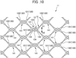
- the plurality of fibers 120 configuring the meshed tubular portion 12 includes a plurality of first fibers 121 and a plurality of second fibers 122.
- the meshed tubular portion 12 includes a multitude of argyle voids formed of the first fibers 121 and the second fibers 122, and includes a plurality of first intersecting points 123 configured by intersections of the plurality of first fibers 121 and the plurality of second fibers 122.
- the material of the synthetic resin fiber configuring the third fiber 131 and the fourth fiber 132 is not limited in particular; however, a material having a high degree of restorability is preferable.
- the biodegradable resin may include homopolymer, copolymer, or blend polymer composed of L-lactic acid, D-lactic acid, DL-lactic acid, glycolic acid, ⁇ -caprolactone, or para-dioxanone.
- Non-biodegradable resin may also be used as long as the material has a high degree of restorability.
- polydioxanone (PDO) is preferably used as the material of the third fiber 131 and the fourth fiber 132.
- FIG. 10 is a view, in which the radial direction of the tubular outer stent 11 in FIG. 9 is rearranged along the direction perpendicular to the paper (direction penetrating the paper) of FIG. 10 . Therefore, the inside of the outer stent 11 in the radial direction is the backside in the vertical direction of the paper of FIG. 10 ; and the outer side of the outer stent 11 in the radial direction is the frontside in the vertical direction of the paper of FIG. 10 .
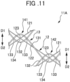
- FIG. 11 is a view illustrating the outer stent 11A according to the first variation of the second embodiment.
- the outer stent 11A of the first variation of the second embodiment is configured to include a first hooking portion 141 (left side in FIG. 11 ) and a second hooking portion 142 (right side in FIG. 11 ).
- the plurality of first hooking portions 141 and the plurality of second hooking portions 142 are spirally and alternately arranged in the circumferential direction in the outer stent 11A.
- the third fiber 131 is arranged frontside of the fourth fiber 132 at one of the two second intersecting points 133 (left side in FIG. 11 ) and arranged backside of the fourth fiber 132 at the other one of the second intersecting points 133 (right side in FIG. 11 ).
- the third fiber 131 and the fourth fiber 132 are arranged in the state of being mutually hookable, in relation to movement in a direction in which the mutually overlapping convex portion of the third fiber 131 and the fourth fiber 132 shrinks in size.
- the first fiber 121 and the second fiber 122 in their entirety are arranged backside of the third fiber 131 and the fourth fiber 132, whereby the third fiber 131 and the fourth fiber 132 in their entirety are arranged frontside of the first fiber 121 and the second fiber 122.
- the outer stent 11A of the first variation of the second embodiment described above in addition to the effects (3a) to (3d) described above, the following effects can be achieved.
- the following effects can be achieved.
- the plurality of configurations are provided, in which the first intersecting point 123 of the meshed tubular portion 12 is arranged in the intersecting region 134 of the wavily woven portion 13; and the third fiber 131 and fourth fiber 132 are arranged in the state of being mutually hookable, in relation to movement in a direction in which the overlapping portion of the third fiber 131 and fourth fiber 132 shrinks in size, and also arranged in the state of not being hookable by the first fiber 121 and the second fiber 122 when the third fiber 131 and fourth fiber 132 move.
- the third fiber 131 and/or the fourth fiber 132 are/is arranged in the state of not being hookable by the first fiber 121 and the second fiber 122, whereby the length in the axial direction is unlikely to be restricted when the outer stent 11A is extended; therefore, loadability into a delivery system can be improved.
- the wavily woven portion 13 is configured to include a row in which the plurality of first hooking portion 141 are arranged side by side in the circumferential direction, and a row without the first hooking portions 141, in the axial direction of the meshed tubular portion 12 having the plurality of first intersecting points 123.
- the first intersecting point 123 is arranged in the intersecting region 134 of the wavily woven portion 13 in the first hooking portion 141, in the row in which the plurality of first hooking portions 141 are arranged side by side in the circumferential direction.
- the plurality of first intersecting points 123 are arranged side by side in the circumferential direction, in the row without the first hooking portions 141.
- the rows of the plurality of first hooking portions 141 arranged in the circumferential direction are arranged so as to be spaced one row apart from each other in the axial direction.
- the rows without the first hooking portions 141 are provided, instead of packing the first hooking portions 141 in the axial direction of the outer stent 11B, whereby the length in the axial direction is unlikely to be restricted by the third fiber 131 and the fourth fiber 132 when the outer stent 11B is extended; therefore, loadability into a delivery system can be improved.
- FIG. 13 is a view illustrating the outer stent 11C according to the third variation of the second embodiment.
- the outer stent 11C of the third variation of the second embodiment includes a plurality of loops 135 formed at the top of the peaks of the wave-shaped fourth fiber 132.
- the loop 135 is formed into a loop shape surrounding the first fiber 121, the second fiber 122, the third fiber 131, and the fourth fiber 132, in which the first intersecting point 123 of the meshed tubular portion 12 is arranged in the intersecting region 134 of the wavily woven portion 13.
- the plurality of loops 135 may be consecutively provided at the top of the peaks of the wave-shaped fourth fiber 132, or may be intermittently provided at the top of the plurality of peaks of the wave-shaped fourth fiber 132.
- the loops 135 may not be configured to surround all of the first fiber 121, the second fiber 122, the third fiber 131, and the fourth fiber 132, or may be configured to surround only part of the first fiber 121, the second fiber 122, the third fiber 131, and the fourth fiber 132.
- the loops 135 are provided at the top of the peaks of the wave-shaped third fiber 131 and/or the wave-shaped fourth fiber 132.
- the loops 135 can apply a contraction force in the radial direction; therefore, the diametrical size of the outer stent 11C can be controlled.
- FIG. 14 is a perspective view illustrating the outer stent 110 according to the fourth variation of the second embodiment of the present invention.
- FIG. 15 is an enlarged view of the outer stent 110 illustrated in FIG. 14 .
- one side in the axial direction is referred to as a first direction D1
- the other side in the axial direction is referred to as a second direction D2.
- one side in the circumferential direction is referred to as a third direction D3 (left side of FIG. 15 )
- the other side in the circumferential direction is referred to as a fourth direction D4 (right side of FIG. 15 ).
- the synthetic resin stent of the present embodiment is the outer stent 110 composed of biodegradable fiber, and includes a first bent woven portion 200 (first woven component portion) and a second bent woven portion 300 (second woven component portion) arranged so as to be woven in the first bent woven portion 200.
- the first bent woven portion 200 is formed into a mesh, in which a plurality of fibers 220 repeatedly bent so as to extend in the axial direction are arranged in the circumferential direction and formed into a tubular structure.
- the fiber 220 configuring the first bent woven portion 200 is configured with a plurality of first fibers 221 and a plurality of second fibers 222.
- the first fiber 221 and the second fiber 222 both include a plurality of bent portions including peaks convex toward the third direction D3 side and peaks convex toward the fourth direction D4 side. As viewed from the side, the first fiber 221 and the second fiber 222 are arranged to have bent portions overlapping with each other and intersect in the first intersecting region 223. The first fiber 221 and the second fiber 222 are formed such that the region surrounded by the first fiber 221 and the second fiber 222 is an opening having a substantially diamond shape in the first intersecting region 223.
- the first intersecting region 223 is formed such that the region surrounded by the first fiber 221 and the second fiber 222 is an opening.
- the size of the opening of the first intersecting region 223 is not limited.
- the first fiber 221 and the second fiber 222 may pull each other in the overlapping portion in a direction to shrink in size, so that the first fiber 221 and the second fiber 222 may be hooked by each other, whereby the region surrounded by the first 221 and the second fiber 222 may not be an opening.
- the bent portions of the third fiber 231 and the fourth fiber 232 are hooked by each other in the second intersecting region 233, and the region surrounded by the third fiber 231 and the fourth fiber 232 is not an opening.
- the second intersecting regions 233 are arranged side by side in the axial direction and the circumferential direction of the second bent woven portion 300.
- the bent portion convex toward the fourth direction D4 side in the first fiber 221 and the second fiber 222 passes the frontside of the third fiber 231 and the fourth fiber 232 on the apex side of the convex portion (fourth direction D4 side), and passes the frontside of the third fiber 231 and the fourth fiber 232 on the opening side of the convex portion (third direction D3 side).
- the bent portion convex toward the third direction D3 side in the first fiber 221 and the second fiber 222 passes the frontside of the bent portion convex toward the fourth direction D4 side.
- the outer stent 110 as described above may be manufactured by forming the second bent woven portion 300 and then forming the first bent woven portion 200, or conversely, by forming the first bent woven portion 200 and then forming the second bent woven portion 300.
- the outer stent 110 configured as described above is formed into a tubular structure with the first fiber 221 and the second fiber 222 repeatedly bent so as to be inclined with respect to the axial direction and extending in the axial direction in the first bent woven portion 200, whereby the shape of the stent is maintained in the tubular structure.
- the second bent woven portion 300 is woven into the first bent woven portion 200, the second bent woven portion 300 (third fiber 231 and fourth fiber 232) is formed of synthetic resin fiber having a higher expansion force than the first bent woven portion 200 (first fiber 221 and second fiber 222), and the bent portion thereof has a property of returning to a straight line.
- the second bent woven portion 300 is woven and repeatedly bent so as to circle the first bent woven portion 200 in the circumferential direction, whereby the second 300 can apply a force to increase the diameter of the outer stent 110, and can enhance the expansion force.
- the expansion force of the outer stent 110 in the radial direction can be strengthened to achieve self-expandability. Adherence to the wall of the gastrointestinal tract can be increased, and trackability to gastrointestinal motility can be achieved.
- the outer stent 110 is configured to include the tubular first bent woven portion 200 composed of one or more fibers formed into a mesh, and the second bent woven portion 300 composed of one or more fibers annularly arranged so as to be woven into the first bent woven portion 200;
- the first bent woven portion 200 is configured to include the plurality of first fibers 221 repeatedly bent so as to be inclined at a predetermined angle with respect to the axial direction and extending in the axial direction, the plurality of second fiber 222 repeatedly bent so as to be inclined at a predetermined angle with respect to the axial direction and extending in the axial direction and arranged to include a portion intersecting with the first fiber 221, and the plurality of first intersecting regions 223 configured by intersections of the plurality of first fibers 221 and the plurality of second fibers 222;
- the second bent woven portion 300 is configured to include the plurality of third fibers 231 repeatedly bent so as to be inclined at a predetermined angle with respect to the axial direction and extending in the circum
- the first fiber 221 and the second fiber 222 repeatedly bent so as to be inclined at a predetermined angle with respect to the axial direction and extending in the axial direction maintains the first bent woven portion 200 in the tubular structure, whereby the tubular structure of the outer stent 110 is maintained.
- the second bent woven portion 300 is woven into the first bent woven portion 200, and the first intersecting region 223 of the first bent woven portion 200 and the second intersecting region 233 of the second bent woven portion 300 are arranged to at least partially overlap with each other, whereby the second bent woven portion 300 can apply a force to increase the diameter, and can enhance the expansion force in the radial direction.
- the expansion force of the outer stent 110 in the radial direction can be strengthened to achieve self-expandability.
- Adherence to the wall of the gastrointestinal tract can be increased, and trackability to gastrointestinal motility can be achieved. Therefore, the stent can ensure loadability into a fine tubular member such as a delivery system, in which migration of the stent is unlikely to occur after placement at the affected site of the natural tracts.
- the first fiber 221 is arranged in the state of being hookable by one or more of the third fiber 231 and the fourth fiber 232, in relation to movement in a direction in which the overlapping portion of the first fiber 221 and the second fiber 222 shrinks in size; and the second fiber 222 is arranged in the state of being hookable by one or more of the third fiber 231 and the fourth fiber 232, in relation to movement in a direction in which the overlapping portion of the first fiber 221 and the second fiber 222 shrinks in size.
- the outer stent 11A of the first variation of the second embodiment (see FIG. 11 ) and the outer stent 11B of the second variation of the second embodiment (see FIG. 12 ) are manufactured by braiding six PLA fibers (three fibers having a fiber diameter of 0.2 mm, and three fibers having a fiber diameter of 0.3 mm), and using PDO fiber having a fiber diameter of 0.15 mm to 0.22 mm to manufacture a wave shape.
- the outer stent 11C of the third variation of the second embodiment (see FIG.
- the outer stents 11A, 11B and 11C are formed by weaving and winding the PLA fiber around the PDO fiber having a wave shape, whereby the shape of the stents is unlikely to collapse.
- the outer stents 11A, 11B and 11C are manufactured under the conditions described above, whereby a stent loadable into a delivery system for the small intestine ( ⁇ 2.8 mm) can be achieved.
- the diameter of the delivery system increases and the fiber diameter can increase as well, whereby a stent having further higher strength can be expected to be manufactured.
- the fiber diameter as well as the stent diameter and length may be arbitrary.
- the biodegradable stent composed of biodegradable fiber has been used as a synthetic resin stent in the embodiments, which are not limited.
- nonbiodegradable synthetic resin fiber may be used to compose a stent.
- the plurality of first hooking portions 141 are provided to the outer stent 11 in its entirety, in the second embodiment.
- the first hooking portions 141 and the second hooking portions 142 are alternately provided, in the third variation of the second embodiment.
- the plurality of first hooking portions 141 are arranged side by side in the circumferential direction, in the second variation of the second embodiment.
- the present invention is not limited to the embodiments, and the first hooking portions 141 and/or the second hooking portions 142 may not be provided to the biodegradable stent in its entirety, or may be provided to part of the biodegradable stent.
- the loop 135 is provided at the top of the peaks of the wave-shaped fourth fiber 132, which is not limited, and may be provided at the top of the peaks at the wave-shaped third fiber 131.
- the biodegradable stent composed of biodegradable fiber is used as a synthetic resin stent in the embodiments, which are not limited.
- nonbiodegradable synthetic resin fiber may be used to compose a stent.
- the biodegradable stent 1 is configured by combining the inner stent 2 and the outer stent 5 in the first embodiment
- the biodegradable stent 10 is configured by combining the inner stent 6 and the outer stent 11 in the second embodiment; however, the present invention is not limited thereto.
- the biodegradable stent may be configured by combining the inner stent 2 of the first embodiment and the outer stent 11 of the second embodiment, or may be configured by combining the inner stent 6 of the second embodiment and the outer stent 5 of the first embodiment.
Landscapes
- Health & Medical Sciences (AREA)
- Engineering & Computer Science (AREA)
- Biomedical Technology (AREA)
- Heart & Thoracic Surgery (AREA)
- Cardiology (AREA)
- Oral & Maxillofacial Surgery (AREA)
- Transplantation (AREA)
- Vascular Medicine (AREA)
- Life Sciences & Earth Sciences (AREA)
- Animal Behavior & Ethology (AREA)
- General Health & Medical Sciences (AREA)
- Public Health (AREA)
- Veterinary Medicine (AREA)
- Optics & Photonics (AREA)
- Physics & Mathematics (AREA)
- Media Introduction/Drainage Providing Device (AREA)
Claims (16)
- Kunstharzstent (1), aufweisend:einen ersten Stent (2) mit einem ersten Stentkorpus (3), der aus einer synthetischen Harzfaser zu einer rohrförmigen Struktur mit einem Netz ausgeformt ist, wobei der erste Stent (2) aus einem Zustand mit reduziertem Durchmesser zu einem Zustand mit erweitertem Durchmesser verformbar ist; undeinen zweiten Stent (5), der zu einer rohrförmigen Struktur mit einem Netz ausgeformt ist, das dichter als das Netz des ersten Stentkorpus (3) ist, wobei der zweite Stent (5) so angeordnet ist, dass er einen Außenumfang des ersten Stentkorpus (3) umhüllt und aus dem Zustand mit reduziertem Durchmesser zu dem Zustand mit erweitertem Durchmesser verformbar ist,dadurch gekennzeichnet, dass der erste Stentkorpus (3) gebildet wird, indem eine Mehrzahl von polygonalen ringförmigen Abschnitten (311) nebeneinander in einer Längsrichtung des ersten Stents (2) verbunden werden, in einem Zustand, in dem die polygonalen ringförmigen Abschnitte (311), die aus einer synthetischen Harzfaser zu einer polygonalen ringförmigen Gestalt ausgeformt sind, so gebogen oder gekrümmt sind, dass sie in der Längsrichtung konvex sind,die Mehrzahl von polygonalen ringförmigen Abschnitten (311) eine Paar gebogene Abschnitte (312, 313), die so gebogen sind, dass sie in der Längsrichtung zu einer Seite hin konvex sind, und ein Paar gebogene Abschnitte (312, 313) aufweisen, die so gebogen sind, dass sie in der Längsrichtung zur anderen Seite hin konvex sind,die Mehrzahl von polygonalen ringförmigen Abschnitten (311) ausgebildet werden, indem die Mehrzahl von polygonalen ringförmigen Abschnitten (311) nebeneinander in der Längsrichtung auf solche Weise verbunden werden, dass die gebogenen Abschnitte (312, 313) der Mehrzahl von polygonalen ringförmigen Abschnitten (311), die einander zugewandt sind, durch einen rohrförmigen Verbindungsabschnitt (32) in einem Zustand verbunden sind, bei dem die gebogenen Abschnitte (312, 313) von benachbarten polygonalen ringförmigen Abschnitten (311) einander zugewandt angeordnet sind, undein Paar benachbarte polygonale ringförmige Abschnitte (311) so verbunden sind, dass wechselseitige konvexe Abschnitte, die aus einer synthetischen Harzfaser der benachbarten polygonalen ringförmigen Abschnitte (311) bestehen, miteinander mit dem rohrförmigen Verbindungsabschnitt (32) verbunden sind, der ein Paar gebogene Abschnitte (312) verbindet, und die wechselseitigen konvexen Abschnitte, die aus einer synthetischen Harzfaser der benachbarten polygonalen ringförmigen Abschnitte (311) bestehen, miteinander mit dem rohrförmigen Verbindungsabschnitt (32) verbunden sind, der ein Paar gebogene Abschnitte (313) verbindet.
- Kunstharzstent (1) nach Anspruch 1, wobei der erste Stent (2) darüber hinaus einen am Ende vergrößerten Durchmesserabschnitt (4) umfasst, der mit mindestens einem Ende des ersten Stentkorpus (3) in der Längsrichtung verbunden ist, wobei der am Ende vergrößerte Durchmesserabschnitt (4) im Durchmesser größer ist als der erste Stentkorpus (3).
- Kunstharzstent (1) nach Anspruch 2, wobei
der am Ende vergrößerte Durchmesserabschnitt (4), der aus einer synthetischen Harzfaser mit einem kleineren Durchmesser als derjenige des ersten Stentkorpus (3) gebildet ist, in Form einer polygonalen ringförmigen Struktur ausgebildet ist, die stärker polygonal ist als die polygonalen ringförmigen Abschnitte (311). - Kunstharzstent (10) nach Anspruch 1, wobeider erste Stent (6) ein Stent ist, der einen Endaufweitungsabschnitt (72) umfasst, welcher an einem Ende in einer Axialrichtung angeordnet ist, wobei der erste Stent aus Drähten (60) gebildet ist,eine Mehrzahl von Scheitelpunkten (721), die aus Spitzenecken bestehen, welche in der Axialrichtung nach außen vorragen, in einer Umfangsrichtung aufeinanderfolgend angeordnet sind, wodurch der Endaufweitungsabschnitt (72), in Axialrichtung gesehen, zu einer ringförmigen Gestalt ausgeformt ist,ein Winkel (θ), der durch zwei Seiten (721a, 721a) jedes der Scheitelpunkte (721) gebildet ist, 80° oder weniger in einem Zustand beträgt, in dem der Stent (6) in den Magen-Darm-Trakt eingesetzt ist, unddie Anzahl der Mehrzahl von Scheitelpunkten (721) drei bis elf beträgt.
- Kunstharzstent (10) nach Anspruch 4, wobei die zwei Seiten (721a, 721a), die jeden der Scheitelpunkte (721) bilden, aus zwei Seiten (611a, 611a) eines Endgitters (611) bestehen, das an einem Ende in der Axialrichtung angeordnet ist.
- Kunstharzstent (10) nach Anspruch 5, wobeider erste Stent (6) eine Mehrzahl von Gittern (61) umfasst, die nebeneinander in Axialrichtung angeordnet sind, unddas Endgitter (611) an einem Ende der Mehrzahl von Gittern (61) angeordnet ist.
- Kunstharzstent (10) nach einem der Ansprüche 4 bis 6, wobei eine Seitenlänge einer Seite (721a) der zwei Seiten (721a, 721a), die jeden der Scheitelpunkte (721) bilden, 16 mm bis 22 mm beträgt.
- Kunstharzstent (10) nach einem der Ansprüche 4 bis 7, wobei benachbarte Scheitelpunkte (721) der Scheitelpunkte des Endaufweitungsabschnitts (72) an einem Schnittpunkt zur äußersten Endseite in der Axialrichtung befestigt sind.
- Kunstharzstent (1) nach einem der Ansprüche 1 und 4 bis 8, wobeider zweite Stent (11) ein Kunstharzstent (1) ist, der einen ersten Webkomponentenabschnitt (12), der rohrförmig ist und aus einer Mehrzahl von Fasern (121, 122) besteht, die zu einem Netz verwoben sind, und einen zweiten Webkomponentenabschnitt (13) umfasst, der aus einer Mehrzahl von Fasern (131, 132) besteht, die so angeordnet sind, dass sie in den ersten Webkomponentenabschnitt (12) eingewoben und in eine ringförmige Gestalt gebracht sind,der erste Webkomponentenabschnitt (12) eine Mehrzahl von ersten Fasern (121), die sich unter einem vorbestimmten Winkel geneigt in Bezug auf die Axialrichtung erstrecken, eine Mehrzahl von zweiten Fasern (122), die sich so erstrecken, dass sie sich mit den ersten Fasern (121) kreuzen, und eine Mehrzahl von ersten Kreuzungspunkten (123) umfasst, die aus Schnittpunkten der Mehrzahl von ersten Fasern (121) und der Mehrzahl von zweiten Fasern (122) ausgebildet sind,der zweite Webkomponentenabschnitt (13) eine Mehrzahl von wellenförmigen dritten Fasern (131), die so angeordnet sind, dass sie in der Axialrichtung voneinander beabstandet sind, und eine Mehrzahl von wellenförmigen vierten Fasern (132) umfasst, die so angeordnet sind, dass sie in der Axialrichtung voneinander beabstandet sind, undmindestens ein erster Kreuzungspunkt (123) aus der Mehrzahl von ersten Kreuzungspunkten (123) in Schnittbereichen (134) angeordnet ist, die von den dritten Fasern (131) und vierten Fasern (132) umgeben sind.
- Kunstharzstent (1) nach Anspruch 9, wobeidie Mehrzahl von Schnittbereichen (134) nebeneinander in der Umfangsrichtung des ersten Webkomponentenabschnitts (12) gebildet sind, unddie Mehrzahl von ersten Kreuzungspunkten (123) nebeneinander in der Umfangsrichtung des ersten Webkomponentenabschnitts (12) und jeweils in der Mehrzahl von Schnittbereichen (134) angeordnet sind.
- Kunstharzstent (1) nach Anspruch 9 oder 10, wobeiin einer Konfiguration, bei welcher die ersten Kreuzungspunkte (123) in den jeweiligen Schnittbereichen (134) angeordnet sind,die dritten Fasern (131) in einem Zustand angeordnet sind, in dem eine oder mehrere der ersten Fasern (121), der zweiten Fasern (122) und der vierten Fasern (132) in sie eingehängt werden kann bzw. können, in Relation zu einer Bewegung in einer Richtung, in der ein Überlappungsabschnitt der dritten Fasern (131) und vierten Fasern (132) in der Größe schrumpft, unddie vierten Fasern (132) in einem Zustand angeordnet sind, in dem eine oder mehrere der ersten Fasern (121), der zweiten Fasern (122) und der dritten Fasern (131) in sie eingehängt werden kann bzw. können, in Relation zu einer Bewegung in einer Richtung, in der der Überlappungsabschnitt der dritten Fasern (131) und vierten Fasern (132) in der Größe schrumpft.
- Kunstharzstent (1) nach Anspruch 11, darüber hinaus aufweisendeinen Mehrzahl von Konfigurationen, bei denen der erste Kreuzungspunkt (123) in dem Schnittbereich (134) angeordnet ist, wobeider Kunstharzstent (1) so ausgebildet ist, dass er teilweise eine Konfiguration umfasst, bei der die dritten Fasern (131) und vierten Fasern (132) in einem Zustand angeordnet sind, in dem sie wechselseitig eingehängt werden können, in Relation zu einer Bewegung in einer Richtung, in der der Überlappungsabschnitt der dritten Fasern (131) und vierten Fasern (132) in der Größe schrumpft, und in einem Zustand angeordnet sind, in dem die ersten Fasern (121) und zweiten Fasern (122) nicht in sie eingehängt werden können, wenn sich die dritten Fasern (131) und vierten Fasern (132) bewegen.
- Kunstharzstent (1) nach einem der Ansprüche 9 bis 12, wobei eine Schlaufe (135) mit einer Schlaufenform am Kopfende der Scheitelpunkte der wellenförmigen dritten Fasern (131) und/oder der wellenförmigen vierten Fasern (132) gebildet ist, wobei die Schlaufe (135) so angeordnet ist, dass sie eine oder mehrere der ersten Fasern (121), zweiten Fasern (122), dritten Fasern (131) und vierten Fasern (132) umgibt.
- Kunstharzstent (1) nach einem der Ansprüche 9 bis 13, wobei der zweite Webkomponentenabschnitt (13) aus einer synthetischen Harzfaser mit einer Expansionskraft ausgebildet ist, die höher als die des ersten Webkomponentenabschnitts (12) ist.
- Kunstharzstent (1) nach einem der Ansprüche 1 und 4 bis 8, wobeider zweite Stent (110) ein Kunstharzstent ist, der einen ersten Webkomponentenabschnitt (200), der rohrförmig ist und aus einer oder mehreren Fasern besteht, die in Form eines Netzes ausgebildet sind, und einen zweiten Webkomponentenabschnitt (330) umfasst, der so angeordnet ist, dass er in den ersten Webkomponentenabschnitt (200) eingewoben ist und aus einer oder mehreren Fasern besteht, die in eine ringförmige Gestalt gebracht sind,der erste Webkomponentenabschnitt (200) eine Mehrzahl von ersten Fasern (221), die wiederholt so gebogen sind, dass sie unter einem vorbestimmten Winkel in Bezug auf die Axialrichtung geneigt sind und sich in der Axialrichtung erstrecken, eine Mehrzahl von zweiten Fasern (222), die so angeordnet sind, dass sie einen Abschnitt umfassen, der sich mit den ersten Fasern schneidet, und wiederholt so gebogen sind, dass sie unter einem vorbestimmten Winkel in Bezug auf die Axialrichtung geneigt sind und sich in der Axialrichtung erstrecken, und eine Mehrzahl von ersten Schnittbereichen (223) umfasst, die aus Schnittpunkten der Mehrzahl von ersten Fasern (221) und der Mehrzahl von zweiten Fasern (222) ausgebildet sind,der zweite Webkomponentenabschnitt (300) eine Mehrzahl von dritten Fasern (231), die wiederholt so gebogen sind, dass sie unter einem vorbestimmten Winkel in Bezug auf die Axialrichtung geneigt sind und sich in der Umfangsrichtung erstrecken, eine Mehrzahl von vierten Fasern (232), die so angeordnet sind, dass sie einen Abschnitt umfassen, der sich mit den dritten Fasern (231) schneidet, und wiederholt so gebogen sind, dass sie unter einem vorbestimmten Winkel in Bezug auf die Axialrichtung geneigt sind und sich in der Axialrichtung erstrecken, und eine Mehrzahl von zweiten Schnittbereichen (233) umfasst, die aus Schnittpunkten der Mehrzahl von dritten Fasern (231) und der Mehrzahl von vierten Fasern (232) ausgebildet sind, unddie ersten Schnittbereiche (223) und zweiten Schnittbereiche (233) so angeordnet sind, dass sie zumindest teilweise einander überlappen.
- Kunstharzstent (1) nach Anspruch 15, wobeiin einer Konfiguration, bei welcher der erste Schnittbereich (223) so angeordnet ist, dass er sich mit dem zweiten Schnittbereich (233) überlappt,die ersten Fasern (221) in einem Zustand angeordnet sind, in dem eine oder mehrere der dritten Fasern (231) und vierten Fasern (232) in sie eingehängt werden kann bzw. können, in Relation zu einer Bewegung in einer Richtung, in der ein Überlappungsabschnitt der ersten Fasern (221) und zweiten Fasern (222) in der Größe schrumpft, unddie zweiten Fasern (222) ) in einem Zustand angeordnet sind, in dem eine oder mehrere der dritten Fasern (231) und vierten Fasern (232) in sie eingehängt werden kann bzw. können, in Relation zu einer Bewegung in einer Richtung, in der ein Überlappungsabschnitt der ersten Fasern (221) und zweiten Fasern (222) in der Größe schrumpft.
Applications Claiming Priority (2)
| Application Number | Priority Date | Filing Date | Title |
|---|---|---|---|
| JP2019063124 | 2019-03-28 | ||
| PCT/JP2020/014487 WO2020196912A1 (ja) | 2019-03-28 | 2020-03-30 | 合成樹脂ステント及びステントデリバリーシステム |
Publications (3)
| Publication Number | Publication Date |
|---|---|
| EP3949914A1 EP3949914A1 (de) | 2022-02-09 |
| EP3949914A4 EP3949914A4 (de) | 2023-01-04 |
| EP3949914B1 true EP3949914B1 (de) | 2024-07-03 |
Family
ID=72610548
Family Applications (1)
| Application Number | Title | Priority Date | Filing Date |
|---|---|---|---|
| EP20776461.4A Active EP3949914B1 (de) | 2019-03-28 | 2020-03-30 | Stent aus kunstharz und stenteinbringungssystem |
Country Status (5)
| Country | Link |
|---|---|
| US (1) | US12622793B2 (de) |
| EP (1) | EP3949914B1 (de) |
| JP (1) | JP7484890B2 (de) |
| CN (1) | CN113613600B (de) |
| WO (1) | WO2020196912A1 (de) |
Families Citing this family (6)
| Publication number | Priority date | Publication date | Assignee | Title |
|---|---|---|---|---|
| EP3949915B1 (de) * | 2019-03-28 | 2024-01-10 | JMS Co., Ltd. | Kunstharzstent |
| WO2021152669A1 (ja) * | 2020-01-27 | 2021-08-05 | オリンパス株式会社 | カバーステント |
| CN113198083B (zh) * | 2021-04-19 | 2023-05-12 | 珠海原妙医学科技股份有限公司 | 一种输尿管支架及制造方法 |
| JPWO2024154279A1 (de) * | 2023-01-19 | 2024-07-25 | ||
| EP4659715A1 (de) * | 2023-02-03 | 2025-12-10 | SB-Kawasumi Laboratories, Inc. | Herstellungsverfahren für stent mit saiten, stent mit saiten und stenteinführungsvorrichtung |
| CN119632740B (zh) * | 2024-12-23 | 2026-01-02 | 通桥医疗科技有限公司 | 颈动脉微网编织支架 |
Family Cites Families (18)
| Publication number | Priority date | Publication date | Assignee | Title |
|---|---|---|---|---|
| US5843167A (en) | 1993-04-22 | 1998-12-01 | C. R. Bard, Inc. | Method and apparatus for recapture of hooked endoprosthesis |
| DE4424242A1 (de) * | 1994-07-09 | 1996-01-11 | Ernst Peter Prof Dr M Strecker | In den Körper eines Patienten perkutan implantierbare Endoprothese |
| AU708360B2 (en) * | 1994-09-15 | 1999-08-05 | C.R. Bard Inc. | Hooked endoprosthesis |
| US6241757B1 (en) | 1997-02-04 | 2001-06-05 | Solco Surgical Instrument Co., Ltd. | Stent for expanding body's lumen |
| US6585758B1 (en) * | 1999-11-16 | 2003-07-01 | Scimed Life Systems, Inc. | Multi-section filamentary endoluminal stent |
| JP2003052834A (ja) | 2001-08-10 | 2003-02-25 | Medicos Hirata:Kk | 生体吸収性ステント及びその製造方法 |
| GB0400571D0 (en) * | 2004-01-12 | 2004-02-11 | Angiomed Gmbh & Co | Implant |
| JP2005211292A (ja) * | 2004-01-29 | 2005-08-11 | Piolax Medical Device:Kk | 管状器官の治療具 |
| DE102004048458B4 (de) * | 2004-10-05 | 2020-08-13 | Admedes Schuessler Gmbh | Aneurysmen-Stent zum Implantieren in einen lebenden Körper und Verwendung desselben als ballonexpandierter Aneurysmen-Stent |
| AU2007207602B2 (en) * | 2006-01-18 | 2012-08-23 | Cook Incorporated | Self expanding stent |
| JP4961517B2 (ja) * | 2007-02-20 | 2012-06-27 | 国立大学法人福井大学 | ステント及びそれを用いた管状器官の治療具 |
| US20100318180A1 (en) * | 2009-06-15 | 2010-12-16 | Boston Scientific Scimed, Inc. | Multi-layer stent assembly |
| US20130226282A1 (en) * | 2010-10-29 | 2013-08-29 | Medisourceplus Co., Ltd. | Stent wires, and method for manufacturing such stent wires and stents |
| US10166128B2 (en) * | 2011-01-14 | 2019-01-01 | W. L. Gore & Associates. Inc. | Lattice |
| JP6177259B2 (ja) * | 2015-01-13 | 2017-08-09 | 日本ライフライン株式会社 | ステントおよびステントグラフト |
| JP6470219B2 (ja) * | 2016-03-25 | 2019-02-13 | 日本ライフライン株式会社 | ステントおよび医療機器 |
| KR101822486B1 (ko) * | 2016-07-01 | 2018-01-26 | 주식회사 엠아이텍 | 약물 방출형 융합성 스텐트 |
| JP7451876B2 (ja) * | 2019-03-28 | 2024-03-19 | 株式会社ジェイ・エム・エス | ステント |
-
2020
- 2020-03-30 CN CN202080024262.5A patent/CN113613600B/zh active Active
- 2020-03-30 US US17/599,417 patent/US12622793B2/en active Active
- 2020-03-30 JP JP2021509696A patent/JP7484890B2/ja active Active
- 2020-03-30 EP EP20776461.4A patent/EP3949914B1/de active Active
- 2020-03-30 WO PCT/JP2020/014487 patent/WO2020196912A1/ja not_active Ceased
Also Published As
| Publication number | Publication date |
|---|---|
| JPWO2020196912A1 (de) | 2020-10-01 |
| US12622793B2 (en) | 2026-05-12 |
| EP3949914A4 (de) | 2023-01-04 |
| US20220211524A1 (en) | 2022-07-07 |
| EP3949914A1 (de) | 2022-02-09 |
| CN113613600B (zh) | 2025-01-24 |
| WO2020196912A1 (ja) | 2020-10-01 |
| JP7484890B2 (ja) | 2024-05-16 |
| CN113613600A (zh) | 2021-11-05 |
Similar Documents
| Publication | Publication Date | Title |
|---|---|---|
| US12622793B2 (en) | Synthetic resin stent and stent delivery system | |
| EP3466376B1 (de) | Webverfahren für nasalen sinusstent und daraus hergestellter stent | |
| EP3254643B1 (de) | Verbindungsstent und herstellungsverfahren dafür | |
| JP3815622B2 (ja) | 膨脹可能なステント | |
| EP3369400B1 (de) | Gewebter lumenträger | |
| US6585758B1 (en) | Multi-section filamentary endoluminal stent | |
| EP1903984B1 (de) | Stent und verfahren zu seiner herstellung | |
| DE4424242A1 (de) | In den Körper eines Patienten perkutan implantierbare Endoprothese | |
| EP1813224A2 (de) | Selbstexpandierbarer Stent aus einer Formgedächtnislegierung und Verfahren zu seiner Herstellung | |
| KR101654861B1 (ko) | 스텐트와 그 스텐트 제조방법 | |
| WO2020093066A1 (en) | Woven stent with improved deployment characteristics | |
| EP3949915B1 (de) | Kunstharzstent | |
| KR102614314B1 (ko) | 비외상성 스페이서를 구비한 스텐트 | |
| US10980988B2 (en) | Stent | |
| JP6750255B2 (ja) | ステント | |
| JP7331342B2 (ja) | ステント | |
| US20170172767A1 (en) | Stents for placement in an anatomical passageway and methods | |
| JP7039957B2 (ja) | ステント | |
| WO2020196913A1 (ja) | ステント | |
| KR101645629B1 (ko) | 스텐트와 그 스텐트 제조방법 | |
| JP6729552B2 (ja) | 合成樹脂ステント | |
| US20230225889A1 (en) | Stent, stent delivery system, and stent manufacturing method | |
| JP2017029387A (ja) | 生分解性ステント | |
| JP2004298334A (ja) | 血管径保持性の優れた均一に拡張する柔軟なステント |
Legal Events
| Date | Code | Title | Description |
|---|---|---|---|
| STAA | Information on the status of an ep patent application or granted ep patent |
Free format text: STATUS: THE INTERNATIONAL PUBLICATION HAS BEEN MADE |
|
| PUAI | Public reference made under article 153(3) epc to a published international application that has entered the european phase |
Free format text: ORIGINAL CODE: 0009012 |
|
| STAA | Information on the status of an ep patent application or granted ep patent |
Free format text: STATUS: REQUEST FOR EXAMINATION WAS MADE |
|
| 17P | Request for examination filed |
Effective date: 20211015 |
|
| AK | Designated contracting states |
Kind code of ref document: A1 Designated state(s): AL AT BE BG CH CY CZ DE DK EE ES FI FR GB GR HR HU IE IS IT LI LT LU LV MC MK MT NL NO PL PT RO RS SE SI SK SM TR |
|
| DAV | Request for validation of the european patent (deleted) | ||
| DAX | Request for extension of the european patent (deleted) | ||
| A4 | Supplementary search report drawn up and despatched |
Effective date: 20221201 |
|
| RIC1 | Information provided on ipc code assigned before grant |
Ipc: A61F 2/915 20130101ALI20221125BHEP Ipc: A61F 2/966 20130101ALI20221125BHEP Ipc: A61F 2/90 20130101ALI20221125BHEP Ipc: A61F 2/89 20130101ALI20221125BHEP Ipc: A61F 2/852 20130101ALI20221125BHEP Ipc: A61F 2/848 20130101AFI20221125BHEP |
|
| STAA | Information on the status of an ep patent application or granted ep patent |
Free format text: STATUS: EXAMINATION IS IN PROGRESS |
|
| 17Q | First examination report despatched |
Effective date: 20230811 |
|
| GRAP | Despatch of communication of intention to grant a patent |
Free format text: ORIGINAL CODE: EPIDOSNIGR1 |
|
| STAA | Information on the status of an ep patent application or granted ep patent |
Free format text: STATUS: GRANT OF PATENT IS INTENDED |
|
| INTG | Intention to grant announced |
Effective date: 20240131 |
|
| RIN1 | Information on inventor provided before grant (corrected) |
Inventor name: NISHIHARA, MANAMI Inventor name: FUKUTAKI, SHUJI Inventor name: IDE, JUNICHI |
|
| GRAS | Grant fee paid |
Free format text: ORIGINAL CODE: EPIDOSNIGR3 |
|
| GRAA | (expected) grant |
Free format text: ORIGINAL CODE: 0009210 |
|
| STAA | Information on the status of an ep patent application or granted ep patent |
Free format text: STATUS: THE PATENT HAS BEEN GRANTED |
|
| AK | Designated contracting states |
Kind code of ref document: B1 Designated state(s): AL AT BE BG CH CY CZ DE DK EE ES FI FR GB GR HR HU IE IS IT LI LT LU LV MC MK MT NL NO PL PT RO RS SE SI SK SM TR |
|
| REG | Reference to a national code |
Ref country code: CH Ref legal event code: EP |
|
| REG | Reference to a national code |
Ref country code: DE Ref legal event code: R096 Ref document number: 602020033410 Country of ref document: DE |
|
| REG | Reference to a national code |
Ref country code: LT Ref legal event code: MG9D |
|
| REG | Reference to a national code |
Ref country code: NL Ref legal event code: MP Effective date: 20240703 |
|
| PG25 | Lapsed in a contracting state [announced via postgrant information from national office to epo] |
Ref country code: PT Free format text: LAPSE BECAUSE OF FAILURE TO SUBMIT A TRANSLATION OF THE DESCRIPTION OR TO PAY THE FEE WITHIN THE PRESCRIBED TIME-LIMIT Effective date: 20241104 |
|
| REG | Reference to a national code |
Ref country code: AT Ref legal event code: MK05 Ref document number: 1699043 Country of ref document: AT Kind code of ref document: T Effective date: 20240703 |
|
| PG25 | Lapsed in a contracting state [announced via postgrant information from national office to epo] |
Ref country code: NL Free format text: LAPSE BECAUSE OF FAILURE TO SUBMIT A TRANSLATION OF THE DESCRIPTION OR TO PAY THE FEE WITHIN THE PRESCRIBED TIME-LIMIT Effective date: 20240703 |
|
| PG25 | Lapsed in a contracting state [announced via postgrant information from national office to epo] |
Ref country code: PT Free format text: LAPSE BECAUSE OF FAILURE TO SUBMIT A TRANSLATION OF THE DESCRIPTION OR TO PAY THE FEE WITHIN THE PRESCRIBED TIME-LIMIT Effective date: 20241104 Ref country code: NL Free format text: LAPSE BECAUSE OF FAILURE TO SUBMIT A TRANSLATION OF THE DESCRIPTION OR TO PAY THE FEE WITHIN THE PRESCRIBED TIME-LIMIT Effective date: 20240703 |
|
| PG25 | Lapsed in a contracting state [announced via postgrant information from national office to epo] |
Ref country code: NO Free format text: LAPSE BECAUSE OF FAILURE TO SUBMIT A TRANSLATION OF THE DESCRIPTION OR TO PAY THE FEE WITHIN THE PRESCRIBED TIME-LIMIT Effective date: 20241003 |
|
| PG25 | Lapsed in a contracting state [announced via postgrant information from national office to epo] |
Ref country code: GR Free format text: LAPSE BECAUSE OF FAILURE TO SUBMIT A TRANSLATION OF THE DESCRIPTION OR TO PAY THE FEE WITHIN THE PRESCRIBED TIME-LIMIT Effective date: 20241004 Ref country code: PL Free format text: LAPSE BECAUSE OF FAILURE TO SUBMIT A TRANSLATION OF THE DESCRIPTION OR TO PAY THE FEE WITHIN THE PRESCRIBED TIME-LIMIT Effective date: 20240703 Ref country code: FI Free format text: LAPSE BECAUSE OF FAILURE TO SUBMIT A TRANSLATION OF THE DESCRIPTION OR TO PAY THE FEE WITHIN THE PRESCRIBED TIME-LIMIT Effective date: 20240703 |
|
| PG25 | Lapsed in a contracting state [announced via postgrant information from national office to epo] |
Ref country code: BG Free format text: LAPSE BECAUSE OF FAILURE TO SUBMIT A TRANSLATION OF THE DESCRIPTION OR TO PAY THE FEE WITHIN THE PRESCRIBED TIME-LIMIT Effective date: 20240703 |
|
| PG25 | Lapsed in a contracting state [announced via postgrant information from national office to epo] |
Ref country code: LV Free format text: LAPSE BECAUSE OF FAILURE TO SUBMIT A TRANSLATION OF THE DESCRIPTION OR TO PAY THE FEE WITHIN THE PRESCRIBED TIME-LIMIT Effective date: 20240703 |
|
| PG25 | Lapsed in a contracting state [announced via postgrant information from national office to epo] |
Ref country code: AT Free format text: LAPSE BECAUSE OF FAILURE TO SUBMIT A TRANSLATION OF THE DESCRIPTION OR TO PAY THE FEE WITHIN THE PRESCRIBED TIME-LIMIT Effective date: 20240703 Ref country code: IS Free format text: LAPSE BECAUSE OF FAILURE TO SUBMIT A TRANSLATION OF THE DESCRIPTION OR TO PAY THE FEE WITHIN THE PRESCRIBED TIME-LIMIT Effective date: 20241103 |
|
| PG25 | Lapsed in a contracting state [announced via postgrant information from national office to epo] |
Ref country code: HR Free format text: LAPSE BECAUSE OF FAILURE TO SUBMIT A TRANSLATION OF THE DESCRIPTION OR TO PAY THE FEE WITHIN THE PRESCRIBED TIME-LIMIT Effective date: 20240703 Ref country code: CZ Free format text: LAPSE BECAUSE OF FAILURE TO SUBMIT A TRANSLATION OF THE DESCRIPTION OR TO PAY THE FEE WITHIN THE PRESCRIBED TIME-LIMIT Effective date: 20240703 |
|
| PG25 | Lapsed in a contracting state [announced via postgrant information from national office to epo] |
Ref country code: ES Free format text: LAPSE BECAUSE OF FAILURE TO SUBMIT A TRANSLATION OF THE DESCRIPTION OR TO PAY THE FEE WITHIN THE PRESCRIBED TIME-LIMIT Effective date: 20240703 Ref country code: RS Free format text: LAPSE BECAUSE OF FAILURE TO SUBMIT A TRANSLATION OF THE DESCRIPTION OR TO PAY THE FEE WITHIN THE PRESCRIBED TIME-LIMIT Effective date: 20241003 |
|
| PG25 | Lapsed in a contracting state [announced via postgrant information from national office to epo] |
Ref country code: RS Free format text: LAPSE BECAUSE OF FAILURE TO SUBMIT A TRANSLATION OF THE DESCRIPTION OR TO PAY THE FEE WITHIN THE PRESCRIBED TIME-LIMIT Effective date: 20241003 Ref country code: PL Free format text: LAPSE BECAUSE OF FAILURE TO SUBMIT A TRANSLATION OF THE DESCRIPTION OR TO PAY THE FEE WITHIN THE PRESCRIBED TIME-LIMIT Effective date: 20240703 Ref country code: NO Free format text: LAPSE BECAUSE OF FAILURE TO SUBMIT A TRANSLATION OF THE DESCRIPTION OR TO PAY THE FEE WITHIN THE PRESCRIBED TIME-LIMIT Effective date: 20241003 Ref country code: LV Free format text: LAPSE BECAUSE OF FAILURE TO SUBMIT A TRANSLATION OF THE DESCRIPTION OR TO PAY THE FEE WITHIN THE PRESCRIBED TIME-LIMIT Effective date: 20240703 Ref country code: IS Free format text: LAPSE BECAUSE OF FAILURE TO SUBMIT A TRANSLATION OF THE DESCRIPTION OR TO PAY THE FEE WITHIN THE PRESCRIBED TIME-LIMIT Effective date: 20241103 Ref country code: HR Free format text: LAPSE BECAUSE OF FAILURE TO SUBMIT A TRANSLATION OF THE DESCRIPTION OR TO PAY THE FEE WITHIN THE PRESCRIBED TIME-LIMIT Effective date: 20240703 Ref country code: GR Free format text: LAPSE BECAUSE OF FAILURE TO SUBMIT A TRANSLATION OF THE DESCRIPTION OR TO PAY THE FEE WITHIN THE PRESCRIBED TIME-LIMIT Effective date: 20241004 Ref country code: FI Free format text: LAPSE BECAUSE OF FAILURE TO SUBMIT A TRANSLATION OF THE DESCRIPTION OR TO PAY THE FEE WITHIN THE PRESCRIBED TIME-LIMIT Effective date: 20240703 Ref country code: ES Free format text: LAPSE BECAUSE OF FAILURE TO SUBMIT A TRANSLATION OF THE DESCRIPTION OR TO PAY THE FEE WITHIN THE PRESCRIBED TIME-LIMIT Effective date: 20240703 Ref country code: CZ Free format text: LAPSE BECAUSE OF FAILURE TO SUBMIT A TRANSLATION OF THE DESCRIPTION OR TO PAY THE FEE WITHIN THE PRESCRIBED TIME-LIMIT Effective date: 20240703 Ref country code: BG Free format text: LAPSE BECAUSE OF FAILURE TO SUBMIT A TRANSLATION OF THE DESCRIPTION OR TO PAY THE FEE WITHIN THE PRESCRIBED TIME-LIMIT Effective date: 20240703 Ref country code: AT Free format text: LAPSE BECAUSE OF FAILURE TO SUBMIT A TRANSLATION OF THE DESCRIPTION OR TO PAY THE FEE WITHIN THE PRESCRIBED TIME-LIMIT Effective date: 20240703 |
|
| REG | Reference to a national code |
Ref country code: DE Ref legal event code: R097 Ref document number: 602020033410 Country of ref document: DE |
|
| PG25 | Lapsed in a contracting state [announced via postgrant information from national office to epo] |
Ref country code: DK Free format text: LAPSE BECAUSE OF FAILURE TO SUBMIT A TRANSLATION OF THE DESCRIPTION OR TO PAY THE FEE WITHIN THE PRESCRIBED TIME-LIMIT Effective date: 20240703 Ref country code: RO Free format text: LAPSE BECAUSE OF FAILURE TO SUBMIT A TRANSLATION OF THE DESCRIPTION OR TO PAY THE FEE WITHIN THE PRESCRIBED TIME-LIMIT Effective date: 20240703 Ref country code: SM Free format text: LAPSE BECAUSE OF FAILURE TO SUBMIT A TRANSLATION OF THE DESCRIPTION OR TO PAY THE FEE WITHIN THE PRESCRIBED TIME-LIMIT Effective date: 20240703 |
|
| PG25 | Lapsed in a contracting state [announced via postgrant information from national office to epo] |
Ref country code: EE Free format text: LAPSE BECAUSE OF FAILURE TO SUBMIT A TRANSLATION OF THE DESCRIPTION OR TO PAY THE FEE WITHIN THE PRESCRIBED TIME-LIMIT Effective date: 20240703 |
|
| PG25 | Lapsed in a contracting state [announced via postgrant information from national office to epo] |
Ref country code: SK Free format text: LAPSE BECAUSE OF FAILURE TO SUBMIT A TRANSLATION OF THE DESCRIPTION OR TO PAY THE FEE WITHIN THE PRESCRIBED TIME-LIMIT Effective date: 20240703 Ref country code: IT Free format text: LAPSE BECAUSE OF FAILURE TO SUBMIT A TRANSLATION OF THE DESCRIPTION OR TO PAY THE FEE WITHIN THE PRESCRIBED TIME-LIMIT Effective date: 20240703 |
|
| PLBE | No opposition filed within time limit |
Free format text: ORIGINAL CODE: 0009261 |
|
| STAA | Information on the status of an ep patent application or granted ep patent |
Free format text: STATUS: NO OPPOSITION FILED WITHIN TIME LIMIT |
|
| 26N | No opposition filed |
Effective date: 20250404 |
|
| PG25 | Lapsed in a contracting state [announced via postgrant information from national office to epo] |
Ref country code: SE Free format text: LAPSE BECAUSE OF FAILURE TO SUBMIT A TRANSLATION OF THE DESCRIPTION OR TO PAY THE FEE WITHIN THE PRESCRIBED TIME-LIMIT Effective date: 20240703 |
|
| PG25 | Lapsed in a contracting state [announced via postgrant information from national office to epo] |
Ref country code: MC Free format text: LAPSE BECAUSE OF FAILURE TO SUBMIT A TRANSLATION OF THE DESCRIPTION OR TO PAY THE FEE WITHIN THE PRESCRIBED TIME-LIMIT Effective date: 20240703 |
|
| REG | Reference to a national code |
Ref country code: CH Ref legal event code: H13 Free format text: ST27 STATUS EVENT CODE: U-0-0-H10-H13 (AS PROVIDED BY THE NATIONAL OFFICE) Effective date: 20251023 |
|
| PG25 | Lapsed in a contracting state [announced via postgrant information from national office to epo] |
Ref country code: LU Free format text: LAPSE BECAUSE OF NON-PAYMENT OF DUE FEES Effective date: 20250330 |
|
| GBPC | Gb: european patent ceased through non-payment of renewal fee |
Effective date: 20250330 |
|
| REG | Reference to a national code |
Ref country code: BE Ref legal event code: MM Effective date: 20250331 |
|
| PG25 | Lapsed in a contracting state [announced via postgrant information from national office to epo] |
Ref country code: GB Free format text: LAPSE BECAUSE OF NON-PAYMENT OF DUE FEES Effective date: 20250330 |
|
| PG25 | Lapsed in a contracting state [announced via postgrant information from national office to epo] |
Ref country code: FR Free format text: LAPSE BECAUSE OF NON-PAYMENT OF DUE FEES Effective date: 20250331 |
|
| PG25 | Lapsed in a contracting state [announced via postgrant information from national office to epo] |
Ref country code: BE Free format text: LAPSE BECAUSE OF NON-PAYMENT OF DUE FEES Effective date: 20250331 |
|
| PG25 | Lapsed in a contracting state [announced via postgrant information from national office to epo] |
Ref country code: CH Free format text: LAPSE BECAUSE OF NON-PAYMENT OF DUE FEES Effective date: 20250331 |
|
| PG25 | Lapsed in a contracting state [announced via postgrant information from national office to epo] |
Ref country code: IE Free format text: LAPSE BECAUSE OF NON-PAYMENT OF DUE FEES Effective date: 20250330 |
|
| PGFP | Annual fee paid to national office [announced via postgrant information from national office to epo] |
Ref country code: DE Payment date: 20260319 Year of fee payment: 7 |