EP3948472B1 - System und verfahren zum autonomen betrieb einer maschine - Google Patents
System und verfahren zum autonomen betrieb einer maschine Download PDFInfo
- Publication number
- EP3948472B1 EP3948472B1 EP20782411.1A EP20782411A EP3948472B1 EP 3948472 B1 EP3948472 B1 EP 3948472B1 EP 20782411 A EP20782411 A EP 20782411A EP 3948472 B1 EP3948472 B1 EP 3948472B1
- Authority
- EP
- European Patent Office
- Prior art keywords
- vehicle
- map
- boundary
- autonomous
- computing device
- Prior art date
- Legal status (The legal status is an assumption and is not a legal conclusion. Google has not performed a legal analysis and makes no representation as to the accuracy of the status listed.)
- Active
Links
Images


Classifications
-
- G—PHYSICS
- G05—CONTROLLING; REGULATING
- G05D—SYSTEMS FOR CONTROLLING OR REGULATING NON-ELECTRIC VARIABLES
- G05D1/00—Control of position, course, altitude or attitude of land, water, air or space vehicles, e.g. using automatic pilots
- G05D1/0011—Control of position, course, altitude or attitude of land, water, air or space vehicles, e.g. using automatic pilots associated with a remote control arrangement
- G05D1/0044—Control of position, course, altitude or attitude of land, water, air or space vehicles, e.g. using automatic pilots associated with a remote control arrangement by providing the operator with a computer generated representation of the environment of the vehicle, e.g. virtual reality, maps
-
- E—FIXED CONSTRUCTIONS
- E02—HYDRAULIC ENGINEERING; FOUNDATIONS; SOIL SHIFTING
- E02F—DREDGING; SOIL-SHIFTING
- E02F9/00—Component parts of dredgers or soil-shifting machines, not restricted to one of the kinds covered by groups E02F3/00 - E02F7/00
- E02F9/08—Superstructures; Supports for superstructures
- E02F9/0841—Articulated frame, i.e. having at least one pivot point between two travelling gear units
-
- E—FIXED CONSTRUCTIONS
- E02—HYDRAULIC ENGINEERING; FOUNDATIONS; SOIL SHIFTING
- E02F—DREDGING; SOIL-SHIFTING
- E02F9/00—Component parts of dredgers or soil-shifting machines, not restricted to one of the kinds covered by groups E02F3/00 - E02F7/00
- E02F9/20—Drives; Control devices
- E02F9/2025—Particular purposes of control systems not otherwise provided for
- E02F9/205—Remotely operated machines, e.g. unmanned vehicles
-
- E—FIXED CONSTRUCTIONS
- E02—HYDRAULIC ENGINEERING; FOUNDATIONS; SOIL SHIFTING
- E02F—DREDGING; SOIL-SHIFTING
- E02F9/00—Component parts of dredgers or soil-shifting machines, not restricted to one of the kinds covered by groups E02F3/00 - E02F7/00
- E02F9/26—Indicating devices
- E02F9/261—Surveying the work-site to be treated
- E02F9/262—Surveying the work-site to be treated with follow-up actions to control the work tool, e.g. controller
-
- G—PHYSICS
- G05—CONTROLLING; REGULATING
- G05D—SYSTEMS FOR CONTROLLING OR REGULATING NON-ELECTRIC VARIABLES
- G05D1/00—Control of position, course, altitude or attitude of land, water, air or space vehicles, e.g. using automatic pilots
- G05D1/0011—Control of position, course, altitude or attitude of land, water, air or space vehicles, e.g. using automatic pilots associated with a remote control arrangement
- G05D1/0027—Control of position, course, altitude or attitude of land, water, air or space vehicles, e.g. using automatic pilots associated with a remote control arrangement involving a plurality of vehicles, e.g. fleet or convoy travelling
-
- G—PHYSICS
- G05—CONTROLLING; REGULATING
- G05D—SYSTEMS FOR CONTROLLING OR REGULATING NON-ELECTRIC VARIABLES
- G05D1/00—Control of position, course, altitude or attitude of land, water, air or space vehicles, e.g. using automatic pilots
- G05D1/0055—Control of position, course, altitude or attitude of land, water, air or space vehicles, e.g. using automatic pilots with safety arrangements
-
- G—PHYSICS
- G05—CONTROLLING; REGULATING
- G05D—SYSTEMS FOR CONTROLLING OR REGULATING NON-ELECTRIC VARIABLES
- G05D1/00—Control of position, course, altitude or attitude of land, water, air or space vehicles, e.g. using automatic pilots
- G05D1/02—Control of position or course in two dimensions
- G05D1/021—Control of position or course in two dimensions specially adapted to land vehicles
- G05D1/0231—Control of position or course in two dimensions specially adapted to land vehicles using optical position detecting means
- G05D1/0238—Control of position or course in two dimensions specially adapted to land vehicles using optical position detecting means using obstacle or wall sensors
-
- G—PHYSICS
- G05—CONTROLLING; REGULATING
- G05D—SYSTEMS FOR CONTROLLING OR REGULATING NON-ELECTRIC VARIABLES
- G05D1/00—Control of position, course, altitude or attitude of land, water, air or space vehicles, e.g. using automatic pilots
- G05D1/02—Control of position or course in two dimensions
- G05D1/021—Control of position or course in two dimensions specially adapted to land vehicles
- G05D1/0255—Control of position or course in two dimensions specially adapted to land vehicles using acoustic signals, e.g. ultra-sonic singals
-
- G—PHYSICS
- G05—CONTROLLING; REGULATING
- G05D—SYSTEMS FOR CONTROLLING OR REGULATING NON-ELECTRIC VARIABLES
- G05D1/00—Control of position, course, altitude or attitude of land, water, air or space vehicles, e.g. using automatic pilots
- G05D1/02—Control of position or course in two dimensions
- G05D1/021—Control of position or course in two dimensions specially adapted to land vehicles
- G05D1/0276—Control of position or course in two dimensions specially adapted to land vehicles using signals provided by a source external to the vehicle
- G05D1/0278—Control of position or course in two dimensions specially adapted to land vehicles using signals provided by a source external to the vehicle using satellite positioning signals, e.g. GPS
-
- G—PHYSICS
- G05—CONTROLLING; REGULATING
- G05D—SYSTEMS FOR CONTROLLING OR REGULATING NON-ELECTRIC VARIABLES
- G05D1/00—Control of position, course, altitude or attitude of land, water, air or space vehicles, e.g. using automatic pilots
- G05D1/20—Control system inputs
- G05D1/22—Command input arrangements
- G05D1/221—Remote-control arrangements
- G05D1/222—Remote-control arrangements operated by humans
- G05D1/224—Output arrangements on the remote controller, e.g. displays, haptics or speakers
- G05D1/2244—Optic
- G05D1/2245—Optic providing the operator with a purely computer-generated representation of the environment of the vehicle, e.g. virtual reality
- G05D1/2246—Optic providing the operator with a purely computer-generated representation of the environment of the vehicle, e.g. virtual reality displaying a map of the environment
-
- G—PHYSICS
- G05—CONTROLLING; REGULATING
- G05D—SYSTEMS FOR CONTROLLING OR REGULATING NON-ELECTRIC VARIABLES
- G05D1/00—Control of position, course, altitude or attitude of land, water, air or space vehicles, e.g. using automatic pilots
- G05D1/20—Control system inputs
- G05D1/22—Command input arrangements
- G05D1/221—Remote-control arrangements
- G05D1/225—Remote-control arrangements operated by off-board computers
-
- G—PHYSICS
- G05—CONTROLLING; REGULATING
- G05D—SYSTEMS FOR CONTROLLING OR REGULATING NON-ELECTRIC VARIABLES
- G05D1/00—Control of position, course, altitude or attitude of land, water, air or space vehicles, e.g. using automatic pilots
- G05D1/20—Control system inputs
- G05D1/22—Command input arrangements
- G05D1/229—Command input data, e.g. waypoints
- G05D1/2297—Command input data, e.g. waypoints positional data taught by the user, e.g. paths
-
- G—PHYSICS
- G05—CONTROLLING; REGULATING
- G05D—SYSTEMS FOR CONTROLLING OR REGULATING NON-ELECTRIC VARIABLES
- G05D1/00—Control of position, course, altitude or attitude of land, water, air or space vehicles, e.g. using automatic pilots
- G05D1/20—Control system inputs
- G05D1/24—Arrangements for determining position or orientation
- G05D1/246—Arrangements for determining position or orientation using environment maps, e.g. simultaneous localisation and mapping [SLAM]
-
- G—PHYSICS
- G05—CONTROLLING; REGULATING
- G05D—SYSTEMS FOR CONTROLLING OR REGULATING NON-ELECTRIC VARIABLES
- G05D1/00—Control of position, course, altitude or attitude of land, water, air or space vehicles, e.g. using automatic pilots
- G05D1/20—Control system inputs
- G05D1/24—Arrangements for determining position or orientation
- G05D1/247—Arrangements for determining position or orientation using signals provided by artificial sources external to the vehicle, e.g. navigation beacons
- G05D1/248—Arrangements for determining position or orientation using signals provided by artificial sources external to the vehicle, e.g. navigation beacons generated by satellites, e.g. GPS
-
- G—PHYSICS
- G05—CONTROLLING; REGULATING
- G05D—SYSTEMS FOR CONTROLLING OR REGULATING NON-ELECTRIC VARIABLES
- G05D1/00—Control of position, course, altitude or attitude of land, water, air or space vehicles, e.g. using automatic pilots
- G05D1/60—Intended control result
- G05D1/617—Safety or protection, e.g. defining protection zones around obstacles or avoiding hazards
- G05D1/622—Obstacle avoidance
- G05D1/628—Obstacle avoidance following the obstacle profile, e.g. a wall or undulated terrain
-
- G—PHYSICS
- G05—CONTROLLING; REGULATING
- G05D—SYSTEMS FOR CONTROLLING OR REGULATING NON-ELECTRIC VARIABLES
- G05D1/00—Control of position, course, altitude or attitude of land, water, air or space vehicles, e.g. using automatic pilots
- G05D1/60—Intended control result
- G05D1/648—Performing a task within a working area or space, e.g. cleaning
- G05D1/6484—Performing a task within a working area or space, e.g. cleaning by taking into account parameters or characteristics of the working area or space, e.g. size or shape
-
- G—PHYSICS
- G05—CONTROLLING; REGULATING
- G05D—SYSTEMS FOR CONTROLLING OR REGULATING NON-ELECTRIC VARIABLES
- G05D1/00—Control of position, course, altitude or attitude of land, water, air or space vehicles, e.g. using automatic pilots
- G05D1/60—Intended control result
- G05D1/69—Coordinated control of the position or course of two or more vehicles
- G05D1/692—Coordinated control of the position or course of two or more vehicles involving a plurality of disparate vehicles
-
- G—PHYSICS
- G05—CONTROLLING; REGULATING
- G05D—SYSTEMS FOR CONTROLLING OR REGULATING NON-ELECTRIC VARIABLES
- G05D1/00—Control of position, course, altitude or attitude of land, water, air or space vehicles, e.g. using automatic pilots
- G05D1/60—Intended control result
- G05D1/69—Coordinated control of the position or course of two or more vehicles
- G05D1/698—Control allocation
- G05D1/6985—Control allocation using a lead vehicle, e.g. primary-secondary arrangements
-
- G—PHYSICS
- G05—CONTROLLING; REGULATING
- G05D—SYSTEMS FOR CONTROLLING OR REGULATING NON-ELECTRIC VARIABLES
- G05D2105/00—Specific applications of the controlled vehicles
- G05D2105/05—Specific applications of the controlled vehicles for soil shifting, building, civil engineering or mining, e.g. excavators
-
- G—PHYSICS
- G05—CONTROLLING; REGULATING
- G05D—SYSTEMS FOR CONTROLLING OR REGULATING NON-ELECTRIC VARIABLES
- G05D2107/00—Specific environments of the controlled vehicles
- G05D2107/90—Building sites; Civil engineering
-
- G—PHYSICS
- G05—CONTROLLING; REGULATING
- G05D—SYSTEMS FOR CONTROLLING OR REGULATING NON-ELECTRIC VARIABLES
- G05D2109/00—Types of controlled vehicles
- G05D2109/10—Land vehicles
Definitions
- the present disclosure is generally related to the operation of machines such as construction vehicles and, in particular, to a system and method for enabling autonomous or semi-autonomous operation of such vehicles.
- Construction and related fields of work may involve a wide variety of tasks, each of which may require different types of vehicles and other equipment.
- Typical construction vehicles include trench roller compactors, skid steers/skid loaders, excavators, and dump trucks/haulers, any combination of which may be used at a job site.
- Some types of construction vehicles may be remotely operated in order to improve workplace safety at hazardous work sites.
- a trench roller compactor may be steered using a remote control system that uses an infrared signal to provide line-of-sight control with the compactor.
- Other types of construction vehicles may autonomously perform certain repetitive processes, but typically require customized hardware to provide those capabilities.
- US 2018/255704 A1 refers to a method, which may include receiving map data descriptive of a plurality of zones located within a parcel of land and receiving information indicative of a plurality of reference coordinates or objects including at least a first and second reference coordinate or object located on the parcel, in which the first and second reference coordinate or object each has corresponding information for defining boundaries for a first workable zone and a second workable zone on the parcel associated therewith, respectively.
- the method may further include determining the boundaries of the first and second workable zones responsive to detection of at least the first and second reference coordinate or object, respectively.
- the method may also include receiving time-scheduling instructions for the first and second workable zones, and operating the robotic vehicle to remain within the first and second workable zones in response to the time-scheduling instructions.
- WO 2018/055921 A1 discloses a work mode setting unit setting a cooperative work mode for a robot tractor and a manned tractor.
- a positional relationship setting unit sets a positional relationship between the robot tractor and the manned tractor in cases where the cooperative work mode is cooperative work within the same work region.
- a travel path creation unit creates a cooperative travel path including a first travel path on which the robot tractor travels and a second travel path on which the manned tractor travels.
- a priority acceptance unit accepts whether or not to prioritize the maintenance of the positional relationship. In cases where the priority acceptance unit accepts the prioritization of the maintenance of the positional relationship, a cooperative travel path that maintains the positional relationship is created. In cases where the priority acceptance unit does not accept the prioritization of the maintenance of the positional relationship, a cooperative travel path that does not maintain the positional relationship is created.
- US 2011/295423 A1 discloses different illustrative embodiments providing a system for autonomous machine management with a number of autonomous machines, a number of boundaries, a conditional behavior module, and a navigation system.
- the number of autonomous machines is configured to perform area coverage tasks in a worksite.
- the number of nodes is configured to define a number of worksite areas for the worksite.
- the conditional behavior module is executed by a processor unit and configured to determine whether a number of conditions is met for the number of worksite areas.
- the navigation system is configured to operate an autonomous machine to perform the area coverage tasks and move between the number of worksite areas when the number of conditions is met.
- the present invention refers to a system for autonomous or semi-autonomous operation of a vehicle according to claim 1.
- Advantageous embodiments may include features of depending claims.
- the present invention is thus directed to a system and method for autonomous or semi-autonomous operation of a vehicle.
- the system includes a robotics processing unit that may be located on the vehicle, located on a central work site control system that controls a plurality of vehicles, or located on a master vehicle that controls a plurality of slave vehicles.
- the system also includes a machine automation portal (MAP) application configured to be executed on a computing device, such as a personal computing tablet, a smartphone, a smart watch or other wearable device, a personal computer, a laptop computer, a personal digital assistant, smart glasses, a virtual reality (VR) head set, or any other electronic computing device that is capable of wireless communication with the robotics processing unit.
- MAP machine automation portal
- a system for autonomous or semi-autonomous operation of a vehicle in accordance with one exemplary embodiment of the invention described herein comprises: a MAP application configured to be executed on a computing device, wherein the MAP application is configured to enable the computing device to (a) display a map of a work site and (b) provide a graphical user interface that enables a user to define a boundary of an autonomous operating zone on the map; and a robotics processing unit configured to receive the boundary of the autonomous operating zone from the computing device, wherein the robotics processing unit is further configured to control operation of the vehicle so that the vehicle performs a task within the autonomous operating zone.
- a system for autonomous or semi-autonomous operation of a vehicle in accordance with one exemplary embodiment of the invention described herein comprises: a MAP application configured to be executed on a computing device, wherein the MAP application is configured to enable the computing device to (a) display a map of a work site and (b) provide a graphical user interface that enables a user to (i) define a boundary of an autonomous operating zone on the map and (ii) define a boundary of one or more exclusion zones; a robotics processing unit configured to (a) receive the boundary of the autonomous operating zone and the boundary of each exclusion zone from the computing device, (b) generate a planned command path that the vehicle will travel to perform a task within the autonomous operating zone while avoiding each exclusion zone, and (c) control operation of the vehicle so that the vehicle travels the planned command path to perform the task; and wherein the graphical user interface of the MAP application enables the user to transmit an emergency stop command to an emergency stop system to thereby stop operation of the vehicle.
- the present invention is directed to a system and method that enables autonomous or semi-autonomous operation of one or more construction vehicles or other machines.
- references to "one embodiment,” “an embodiment,” “an exemplary embodiment,” or “embodiments” mean that the feature or features being described are included in at least one embodiment of the invention.
- references to “one embodiment,” “an embodiment,” “an exemplary embodiment,” or “embodiments” in this disclosure do not necessarily refer to the same embodiment and are also not mutually exclusive unless so stated and/or except as will be readily apparent to those skilled in the art from the description.
- a feature, structure, function, etc. described in one embodiment may also be included in other embodiments, but is not necessarily included.
- the present invention can include a variety of combinations and/or integrations of the embodiments described herein.
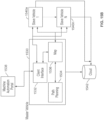
- a system for enabling autonomous or semi-autonomous operation of a construction vehicle or other machine is shown generally as reference numeral 100.
- the machine comprises a conventional construction vehicle that has been modified (i.e., retrofitted) with components to enable autonomous or semi-autonomous operation of the vehicle.
- the machine comprises a construction vehicle that is originally designed with components to enable autonomous or semi-autonomous operation of the vehicle.
- a variety of different types of machines may be operated using the system of FIG. 1 , such as trench roller compactors (an example of which is described below in connection with FIGS.
- skid steers/skid loaders excavators, dump trucks/haulers, mowers, street sweepers, snow blowers and plows, scrapers, and pavers.
- excavators dump trucks/haulers
- mowers street sweepers
- snow blowers and plows snow blowers and plows
- scrapers scrapers
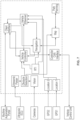
- System 100 includes a variety of different components, including a robotics processing unit 110, a vehicle control unit 112, a controller 114, a hydraulic system and engine controls 116, an ultrasonic electronics control unit (ECU) 118 connected to one or more ultrasonic sensors 120, three-dimensional (3D) depth cameras 122, global positioning system (GPS) receivers 124, and one or more computing devices 126 and 128.
- the construction vehicle comprises a conventional trench roller compactor that includes controller 114 and hydraulic system and engine controls 116, and the remaining components shown in FIG. 1 are provided to enable autonomous or semi-autonomous operation of the vehicle in accordance with the present invention, as described below.
- processing unit 110 may be coupled directly to controller 114 without the use of vehicle control unit 112 (which largely functions as a digital-to-analog converter in the system of FIG. 1 ).
- Robotics processing unit 110 is configured to communicate with one or more computing devices (such as computing devices 126 and 128) via a wireless communications link.
- each computing device is configured to execute a machine automation portal (MAP) application that enables the user to define a boundary for one or more operational areas (e.g., an outer-geo-fence and/or autonomous operating zone) and exclusion zones for a vehicle, configure a task for the vehicle, control operation of the vehicle (e.g., start, pause, and re-start the vehicle), trigger an emergency stop of the vehicle, view other on-site vehicles and assets, view data transmitted by the vehicle (e.g., live sensor data and vehicle diagnostics), view notifications relating to operation of the vehicle (e.g., time remaining for the task, vehicle blocked, etc.), as well as other functions described herein.
- MAP machine automation portal
- Each computing device may comprise a personal computing tablet, a smartphone, a smart watch or other wearable device, a personal computer, a laptop computer, a personal digital assistant, smart glasses, a virtual reality (VR) head set, or any other electronic computing device that is capable of wireless communication with robotics processing unit 110.
- the computing device includes a WiFi transceiver that enables communication with robotics processing unit 110 over a Wi-Fi network (i.e., a wireless network that operates in accordance with the Wi-Fi IEEE 802 communications protocol) and/or a cellular transceiver that enables communication with robotics processing unit 110 over a cellular network (i.e., a network that operates in accordance with the long term evolution (LTE) communications standard or other cellular standards).
- Wi-Fi network i.e., a wireless network that operates in accordance with the Wi-Fi IEEE 802 communications protocol
- a cellular transceiver that enables communication with robotics processing unit 110 over a cellular network (i.e., a network that
- computing device 126 comprises an Apple ® iPad Pro and computing device 128 comprises an Apple ® Watch, each of which is capable of communicating with robotics process node 110 over either a WiFi network or an LTE network.
- computing device 128 comprises an Apple ® Watch, each of which is capable of communicating with robotics process node 110 over either a WiFi network or an LTE network.
- any number of computing devices may be used in accordance with the invention.
- Robotics processing unit 110 is also configured to fuse sensor data received from a variety of different vehicle-mounted sensors, such as GPS receivers, 3D depth cameras, ultrasonic sensors, and other types of sensors known to those skilled in the art.
- the sensors include GPS receivers 124 that are configured to determine the position and orientation of the vehicle (e.g., by implementing real-time kinetic (RTK) positioning).
- Each GPS receiver may comprise, for example, the Duro ® ruggedized GNSS receiver available from Swift Navigation, Inc. of San Francisco, California.
- the sensors also include environmental sensors that are used to detect obstacles in the path of the vehicle.
- the environmental sensors comprise one or more ultrasonic sensors 120 (e.g., the front, side and rear ultrasonic sensors illustrated in FIG. 2A , described below) that are connected to an ultrasonic ECU 118 that aggregates the sensor data.
- the ultrasonic ECU and sensors may comprise, for example, the Off-Highway TD F037S07211 ultrasonic sensor system available from Robert Bosch LLC (Bosch Mobility Solutions USA) of Farmington Hills, Michigan.
- the environmental sensors also comprise 3D depth cameras 122 (e.g., the front and rear depth cameras illustrated in FIG. 2A , described below). Each 3D depth camera may comprise, for example, the CamBoard pico flex 3D camera development kit (which is based on time-of-flight (ToF) technology) available from PMD Technologies AG of Siegen, Germany.
- ToF time-of-flight
- robotics processing unit 110 vehicle control unit 112, and GPS receivers 124 have inertial measurement units (IMUs) that are used for location, orientation, tilt detection and alerting, and compaction sensing.
- IMUs inertial measurement units
- the vehicle may include LiDAR-based safety sensors for triggering an emergency stop when an imminent collision is detected.
- a safety sensor is a natural gas detector that is configured to trigger an emergency stop when unsafe levels of natural gas are detected (indicating a potential leak).
- the mapping and path execution functions may be enhanced, in some embodiments, by sensor suites external to the vehicle, such as a drone-mounted camera or the like that provides the system with image data and/or depth data representing the autonomous operating zone.
- Robotics processing unit 110 is further configured to interface with vehicle control unit 112, which in turn interfaces with the vehicle's original controller 114 and hydraulic system and engine controls 116. As described in greater detail below, robotics processing unit 110 utilizes the information received from the computing devices and the various sensors to provide control data to vehicle control unit 112 and thereby autonomously or semi-autonomously operate the vehicle. In some implementations, the vehicle operates wholly autonomously. In other implementations, the vehicle operates under the control of the user under some conditions (e.g., when the user initiates an emergency stop of the vehicle) and operates autonomously under other conditions.
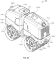
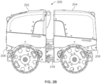
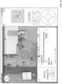
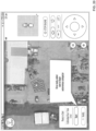
- Compactor 200 comprises a conventional construction vehicle (in this case, an RTSC3 trench roller compactor available from Wacker Neuson Corporation of Menomonee Falls, Wisconsin) that includes a front compartment 202 connected via an articulating center joint to a rear compartment 204.
- GPS receivers (not shown) are located underneath the front and rear hoods of front compartment 202 and rear compartment 404, respectively. It should be understood that these GPS receivers correspond to GPS receivers 124 shown in FIG. 1 .
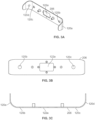
- Front compartment 202 has been modified to include an integrated front bumper 206 that mounts a 3D depth camera and four ultrasonic sensors.
- front bumper 206 includes a generally rectangular-shaped central opening 122a that is sized to receive a camera enclosure for the 3D depth camera, as well as four smaller openings 120a, 120b, 120c and 120d each of which is sized to receive an ultrasonic sensor.
- FIGS. 4A and 4B illustrate an exemplary camera enclosure 240 that may be mounted in central opening 122a of bumper 206 via mounting holes 242, 244, 246 and 248. Camera enclosure 240 is configured so that the camera is positioned at an angle of forty-five degrees with respect to the horizontal plane, as shown in FIG. 4A . Of course, other camera angles may be used for different types of cameras and/or different implementations in accordance with the invention.
- the camera may be connected to robotics processing unit 110 (see FIG. 1 ) via a USB cable that extends through a USB cable chamber 252.
- rear compartment 204 has been modified to include an integrated rear bumper 208 that mounts a 3D depth camera and four ultrasonic sensors (not shown). It should be understood that the configuration of rear bumper 208 is similar to that of front bumper 206. An ultrasonic sensor is also mounted on each side of front compartment 202 and each side of rear compartment 204, wherein two of the four openings for these ultrasonic sensors are shown as reference numbers 120e and 120f in FIG. 2A .
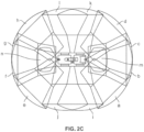
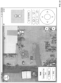
- FIG. 2C illustrates the generally cone-shaped fields of view for the two 3D depth cameras and twelve ultrasonic sensors described in connection with FIG. 2A .
- the fields of view designated a, b, c and d correspond to the four ultrasonic sensors mounted on front bumper 206
- the fields of view designated e, f, g and h correspond to the four ultrasonic sensors mounted on rear bumper 208
- the fields of view designated i, j, k and l correspond to the four ultrasonic sensors mounted on the sides of front compartment 202 and rear compartment 204
- fields of view m and n correspond to the 3D depth cameras mounted on front bumper 206 and rear bumper 208, respectively.
- this sensor arrangement provides a 360 degree field of view around compactor 200.
- the invention is not limited to any specific types of sensors and/or any particular number of sensors, and other arrangements may be used for different implementations within the scope of the invention.
- front compartment 202 includes two infrared sensors 214a and 214b and rear compartment 204 include one infrared sensor 214c, as shown, which enable receipt of control signals to drive the vehicle from a remote control device.
- the infrared sensors are connected to vehicle control unit 112, which watches for an infrared signal from the remote control device and immediately relays any such signal to controller 114, thereby removing all control from other users (including users of computing devices 126 and 128).
- the MAP application will cause a notification to be displayed on the computing devices.
- the remote control device is turned off, the MAP application will enable a user to restart the task on one of computing devices 126 and 128.
- Rear compartment 204 also includes a blue flashing indicator light 212 positioned on top of the compartment and a warning beeper 210 positioned underneath rear bumper 208, as shown, which are activated whenever compactor 200 is operating in the autonomous mode (e.g., when compactor 200 is executing a task requested by one of computing devices 126 and 128).
- a number of the components shown in FIG. 1 are housed within rear compartment 204, including robotics processing unit 110, vehicle control unit 112, ultrasonic ECU 118, antennas for GPS receivers 124, and antennas that enable communication with the Wi-Fi transceiver and/or cellular transceiver of computing devices 126 and 128. These components are preferably housed within a ruggedized enclosure that provides isolated interfaces to each of the components.
- compactor 200 further includes an angle sensor assembly with a rotary position sensor 216 that is utilized to determine the steering angle between front compartment 202 and rear compartment 204.
- front compartment 202 includes a frame plate 218 that supports a hinge 220 and, similarly, rear compartment 204 includes a frame plate 222 that supports a hinge 224.
- Hinge 220 is pivotally connected to hinge 224 via a hinge pin 226 with a pin head 228 and pin locator 230.
- a mounting block 232 is provided to support rotary position sensor 216.
- rotary position sensor 216 comprises the RTY360LVNAX rotary potentiometer available from Honeywell International Inc. of Charlotte, North Carolina.
- Rotary position sensor 216 is configured to provide a position feedback signal of the rotating hinge pin 226 to robotics processing unit 110, which uses this information to determine the steering angle between front compartment 202 and rear compartment 204 in a manner known to those skilled in the art.
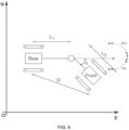
- the steering angle between front compartment 202 and rear compartment 204 may also be determined using the GPS receivers located underneath the front and rear hoods of front compartment 202 and rear compartment 404 (wherein the GPS receiver of the rear compartment will be referred to as GPS 1 and the GPS receiver of the front compartment will be referred to as GPS 2 ). With reference to FIG.
- Table 1 L 1 Distance from vehicle joint to GPS 1 along the center line of the vehicle axis (meters) L 2 Distance from vehicle joint to GPS 2 along the center line of the vehicle axis (meters) D Linear distance between GPS 1 and GPS 2 (meters) D Rate of change in the linear distance (meters/second) ⁇ Vehicle steering angle (degrees) ⁇ Rate of change of steering angle (degrees/second) ⁇ E Error in steering angle ⁇ Degree offset from north to the vehicle's heading (degrees) ⁇ Rate of change of the vehicle's absolute orientation (degrees/second) V Velocity of the vehicle's forward axis (meters/second) GPS 1N distance of GPS 1 from reference point in the north direction (meters) GPS 2N distance of GPS 2 from reference point in the north direction (meters) GPS 1E distance of GPS 1 from reference point in the east direction (meters) GPS 2E distance of GPS 2 from reference point in the east direction (meters)
- the direction of the steering angle may be determined based on the change in measured variables (i.e., distance vector, input commands (left, right, forward, reverse), and angular rate), as shown in the if/then statements shown below:
- both the rotary position sensor 216 and the GPS receivers to determine the steering angle between front compartment 202 and rear compartment 204 provides several advantages.
- a rotary position sensor e.g., rotary potentiometer
- the GPS receivers are used to calibrate the rotary position sensor, thus eliminating the manual calibration step.
- the rotary position sensor and the GPS receivers may be used to refine the guidance, navigation and control algorithms.
- the use of both the rotary position sensor and the GPS receivers provides redundancy and, if the steering angles determined from the two methods differ by more than a predetermined margin, the system may provide an alert to check the sensors.
- the system may utilize only one of these methods to determine the steering angle or may use one or more different methods within the scope of the invention.
- FIG. 7 a block diagram is provided to illustrate the software processes implemented on robotics processing unit 110 of system 100.
- the software processes are generally described below.
- Client Interface This process manages the state of various clients connecting and disconnecting from the vehicle (e.g., the MAP applications residing on one or both of computing devices 126 and 128) and routes incoming and outgoing messages appropriately.
- Ultrasonic Parser This process receives the sensor data from ultrasonic ECU 118 and converts the binary CAN data into a JSON object.
- This process receives the camera frames from 3D depth cameras 122 and converts the depth data into a 3D point cloud.
- Locations 1 and 2 These processes receive the GPS data from GPS receivers 124 and convert the proprietary binary into a JSON object.
- Controller CAN Interface This process receives vehicle data from vehicle control unit 112 and converts the proprietary binary into a JSON object.
- Path Planning This process handles requests from vehicle navigation to plan a route (referred to as a "command path") that will cover the autonomous operating zone defined by the user.
- This process is used to filter the 3D point cloud from 3D depth cameras 122 and broadcast the coordinates of obstacles detected within pre-defined user thresholds.
- Map This process is responsible for holding all information regarding the state of the physical world and vehicles operating within that world, such as the location of one or more operational areas and/or exclusion zones, the position of any detected obstacles, the position of each vehicle, the elevation, the compaction level, etc.
- FIG. 14 is an exemplary map grid showing the cells oriented in a north-east-down (NED) coordinate system, wherein North is positioned on the x-axis and East is positioned on the y -axis.
- NED north-east-down
- the resolution may vary between different implementations-e.g., each cell is 0.5 meters along the x -axis and 0.5 meters along the y -axis in this embodiment.
- boundary true or false
- information on whether the boundary of an exclusion zone is located within that cell i.e., keepout - true or false
- the elevation of that cell i.e., keepout - true or false
- compaction level of that cell i.e., the boundary of an exclusion zone is located within that cell.
- other types of information may be stored in association with each cell, such as information on whether a detected obstacle is located within that cell, information on whether the vehicle is located within that cell, and any other types of information to be displayed to the user. It should be understood that the invention is not limited to the types of information shown in FIG. 14 , and that a variety of different types of information may be stored as needed for a particular implementation.
- Vehicle Controller This process manages the sending of commands for left, right, forward, straight, idle, vibration, engine state and manual control from the MAP application.
- Vehicle Observer This process fuses the GPS, accelerometer and other sensor and state data from any sub-system to combine it into a single source of truth for the vehicle's position, orientation and current operating state.
- RTI Real Time Interface
- This process responds to the command path and manages the sending of waypoints to the control module in order to drive the path (e.g., a new waypoint is sent to the control module when a waypoint is achieved).
- This process also manages the internal task state when received from the map process (e.g., No Task, Task Received, Task Started, Task Paused, Task Blocked, Task Updated, Task Rerouting, Task Completed).
- this process is responsible for requesting new command paths when blocked.
- the software processes shown in FIG. 7 are examples and that one or more of these processes may not be performed by robotics processing unit 110 and/or one or more additional processes may be performed by robotics processing unit 110. Further, it should be understood that one or more of the above software processes may be performed by another component.
- the map and path planning processes may alternatively be performed by a central robotics processing unit located on the same Wi-Fi network or LTE network that is used for communications between robotics processing unit 110 and computing devices 126 and 128. This option may be preferred for implementations that involve the operation of multiple vehicles, as described below, in order to provide centralized map and path planning processes.
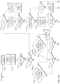
- system 100 of FIG. 1 including robotics processing unit 110 and the software processes shown in FIG. 7 ) are used to perform various methods, including submission of a boundary and update of that boundary upon detection of an obstacle ( FIG. 8 ), autonomous performance of a vehicle task ( FIGS. 9 and 10 ), control of the vehicle ( FIGS. 11a and 11B ), detection of an obstacle in the vehicle's path ( FIG. 12 ), and emergency stop of the vehicle ( FIG. 13 ).
- a method for submitting a boundary and updating the boundary upon detection of an obstacle is shown.
- the steps of this method are performed by different components of system 100, including the MAP application residing on computing device 126 ("Client”), the navigation process of robotics processing unit 110 ("Navigation”), the path planning process of robotics processing unit 110 ("Path Planning”), the map process of robotics processing unit 110 ("Map”), and the environmental sensors, namely, ultrasonic ECU 118 with ultrasonic sensors 120 and 3D depth cameras 122 (“Sensors").
- a map request (Client Map Request) is transmitted to the map process of robotics processing unit 110 for generation of a map, and the map process returns the current map (Map Client Update) to the MAP application.
- the map is generated using aerial satellite photography and/or drone imagery, although other map generation techniques known to those skilled in the art may also be used.
- the MAP application provides a graphical user interface configured to present the map on the display of computing device 126.
- an operational area may comprise an outer geo-fence representing the maximum extent of the area in which the vehicle is permitted to operate.
- the outer geo-fence may, for example, represent the boundaries of a work site.
- the user defines the outer geo-fence by selecting a region on the map presented on the display of computing device 126.
- the outer geo-fence is predefined for a given work site and applied to any task definition generated by a computing device for execution at that site.
- An operational area may also comprise an autonomous operating zone.
- the autonomous operating zone is typically smaller than the outer geo-fence (although it may encompass up to the same area as the outer geo-fence) and defines the boundaries of the task to be autonomously performed by the vehicle.
- the autonomous operating zone defines an area of the work site to be compacted by the compactor. The user defines the autonomous operating zone by selecting a region on the map presented on the display of computing device 126.
- the MAP application on computing device 126 also enables a user to define a boundary for one or more exclusion zones (i.e., keepouts).
- An exclusion zone is an area within the autonomous operating zone that the vehicle is not permitted to enter (e.g., an area containing buildings or other obstacles).
- the user defines an exclusion zone similarly to the autonomous operating zone, e.g., by selection of a region on the map presented on the display of computing device 126.
- the path planning process is configured to generate paths that do not enter the exclusion zones.
- each operational area e.g., outer geo-fence and/or autonomous operating zone
- exclusion zone by selecting a region on the map presented on the display of computing device 126.
- the MAP application enables the user to accurately place three or more markers on the map to create the boundary for each operational area and exclusion zone. Lines are then drawn to connect the markers within the graphical user interface to thereby depict the boundary for the operational area or exclusion zone on the map. These lines may also be labeled with distances so that the user can ensure the accuracy of the scale down to the centimeter.
- the shape of the boundary can be a simple triangle (if three markers are placed by the user), a square or rectangle (if four markers are placed by the user), or a complex polygon (if five or more markers are placed by the user).
- the user (holding computing device 126) walks along the intended path of the boundary while computing device 126 continuously transmits GPS coordinates (i.e., digital breadcrumbs) to define the location of the boundary. Lines are then drawn to connect the GPS coordinates within the graphical user interface to thereby depict the boundary for the operational area or exclusion zone on the map. If necessary, the lines are smoothed out and may also be labeled with distances so that the user can ensure the accuracy of the scale down to the centimeter.
- GPS coordinates i.e., digital breadcrumbs
- the current location of compactor 200 is used as a reference point and the user inputs a distance from compactor 200 for use in placing the markers on the map. Lines are then drawn to connect the markers within the graphical user interface to thereby depict a boundary for the operational area or exclusion zone on the map. Each line segment can be set to a custom length that is input by the user.
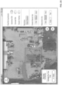
- FIG. 17 is an exemplary screen shot of the MAP application showing various white markers that define an initial boundary for an autonomous operating zone. As can be seen, a user may move these white markers around to adjust the boundary line as desired.
- FIG. 19 is an exemplary screen shot of the MAP application showing the final boundary for the autonomous operating zone after adjustment of the white markers.
- This same process may also be used to define one or more exclusion zones (i.e., keepouts).
- modifications may be made to the coordinates of each marker whenever the vehicle is not operating in autonomous mode. As shown in FIG.
- the boundary configuration (Boundary Config) is transmitted to the map process of robotics processing unit 110 for generation of a map with the defined boundaries (Update Client Boundary and Keepouts), and the map process returns the updated map to the MAP application (Map Client Update).
- the graphical user interface of MAP application is configured to present the updated map on the display of computing device 126.
- the MAP application also provides an augmented reality (AR) mode that enables a user to visualize the virtual boundary of the autonomous operating zone superimposed on a real world view of the area.
- AR augmented reality
- the user can initiate the AR mode by selecting "View in AR" as shown in FIGS. 17 and 19 , which causes the camera of computing device 126 to show the real world view of the area with a digital overlay of the boundary of the autonomous operating zone.
- FIG. 18 is an exemplary screen shot of the MAP application in AR mode in which the boundary (i.e., the dark-shaded boundary with white post markers) is shown as a digital overlay on the real world view of the autonomous operating zone.
- the compactor will stop and reverse direction when it reaches the boundary.
- the MAP application provides the AR view by using image and object detection to observe the vehicle's location in the real world view for use as a reference point. Then, using the GPS coordinates and heading information supplied by the vehicle over the wireless network connection, the MAP application draws each boundary in a way that accurately depicts where the coordinates of that boundary are located in the camera's real world view. For example, with reference to FIG. 14 , assume that compactor 200 is located in cell (2, 3) (i.e., row 2, column 3) and that the resolution of the grid is 0.5 meters (i.e., each cell is 0.5 meters along the x-axis and 0.5 meters along the y-axis).
- the location of the compactor may then be used to draw the boundary from the grid offset-e.g., marking the top boundary at 0.5 meters north (corresponding to cell (1, 3)), the left boundary at 1 meter west (corresponding to cell (2. 1)), the right boundary at 1 meter east (corresponding to cell (2, 5)), and the bottom boundary at 1.5 meters south (corresponding to cell (5, 3)).
- the user instead of relying on aerial satellite photography that may be out-of-date, too pixelated, or too obfuscated to accurately determine where the coordinates meet real world locations, the user can see the real world view of the exact area where the vehicle will be allowed to operate autonomously.
- the user next accesses the MAP application on computing device 126 to submit a coverage task, which may include a task type and/or task details. It can be appreciated that the task types and task details will be dependent on the nature and capabilities of the vehicle.
- the task type may comprise a compacting task (i.e., compact the ground by driving over each square inch in the area of the autonomous operating zone) and the task details may comprise, for example, the compaction level, the path orientation (e.g., 0-90°), the vehicle speed, and the obstacle detection size based on terrain roughness.
- the screen shot of FIG. 19 shows a menu system that enables a user to select the vibration magnitude (via selection of one of the ISO standard icons for off, low, and high), the path orientation (using the slideable scale), and the vehicle speed (via selection of one of the ISO standard icons for slow and fast).
- the settings mode may be accessed to display the menu system shown in FIG. 25 , which enables a user to select the obstacle detection size (via selection of one of the small, medium or large buttons) and the type of measurement units.
- the task type may also comprise a point-to-point travel task (i.e., travel from the current location of the vehicle to a target location within the autonomous operating zone, as specified by computing device 126, while avoiding any obstacles located along the path).
- the task type may comprise a follow-me task in which the compactor closely trails computing device 126 running the MAP application, or a trench mode task in which the compactor navigates inside a deep drench where the sensors continually detect the sides of the trench but do not treat such sides as obstacles that prevent the compactor from moving.
- a grading task for a vehicle with a blade or bucket will be apparent to those skilled in the art, such as a grading task for a vehicle with a blade or bucket.
- the MAP application on computing device 126 transmits a new task request (New Task Request) to the map process of robotics processing unit 110.
- the map process creates the autonomous task based on the task definition (Create Autonomous Task) and transmits a new path request (New Path Request) to the path planning process.
- the path planning process generates a command path within the autonomous operating zone by performing a set of best-effort heuristics to decompose the space into "plowable" subsections, as known to those skilled in the art (i.e., the process is a form of Morse convex cellular decomposition known as Boustrophedon cellular decomposition).
- the generated command path (Command Path) is then transmitted to the map process, which transmits a new autonomous task (New Autonomous Task) to the navigation process.
- the navigation process reports path updates (Reported Path Update) to the map process.
- the environmental sensors i.e., the ultrasonic sensor system and/or 3D depth cameras
- the map process transmits a request for an updated path (Path Update Request) to the path planning process, and the path planning process returns an updated command path (Command Path).
- the map process then transmits the updated command path (Command Path Update) to the navigation process, and also transmits a map update with one or more dynamically-generated exclusion zones (Map Client Update) to the MAP application for display on computing device 126.
- Any dynamically-generated exclusion zone can be overridden (i.e., deleted) by a user of computing device 126 (e.g., upon visual confirmation by the user that no obstacle exists, or that the obstacle is sufficiently small that the vehicle can safely ignore it). In that case, the vehicle will be allowed to drive over that area on a future pass.
- the compactor continues to operate upon detection of an obstacle-i.e., the command path is merely updated to avoid the obstacle.
- the compactor may pause upon detection of an obstacle and wait for input from the user as to whether to override the dynamically-generated exclusion zone, as described above.
- these embodiments would require more manual intervention and, thus, may not be preferred for some implementations.
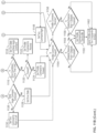
- FIG. 9 a method for autonomously performing a vehicle task is shown. As can be seen, the steps of this method are performed by different components of system 100, including the MAP application residing on computing device 126 ("Client”), the navigation process of robotics processing unit 110 ("Navigation”), the path planning process of robotics processing unit 110 (“Path Planning”), and the map process of robotics processing unit 110 ("Map”) (note that the environmental sensors (“Sensors”) are not involved in this method).
- the MAP application on computing device 126 transmits a new task request (New Task Request) to the map process of robotics processing unit 110.
- the map process creates the autonomous task based on the task definition (Create Autonomous Task) and transmits a new path request (New Path Request) to the path planning process.
- the path planning process generates a command path within the autonomous operating zone, as described above, and the generated command path (Command Path) is transmitted to the map process.
- the map process then transmits a new autonomous task (New Autonomous Task) to the navigation process, and also transmits a map update with the command path (Client Map Update) to the MAP application for display on computing device 126.
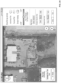
- FIG. 20 is an exemplary screen shot of the MAP application showing the boundary for the autonomous operating zone with the generated command path.
- the user may then start the autonomous task by selecting the Start Engine button on the display of computing device 126 (see FIGS. 17 and 19 ) to start the engine of the compactor, and then selecting the Start button on the display of computing device 126 (see FIG. 20 ).
- the compactor will then move to a new location to begin the autonomous task, as indicated in the exemplary screen shot of the MAP application shown in FIG. 21 .
- the user may select the Stop Engine button on the display of computing device 126 (see FIGS. 20 , 21 and 22 ) at any time during operation of the compactor in order to stop the engine of the compactor.
- the Stop Engine action is different than the emergency stop feature (described below) insofar as the user may select the Start Engine button to immediately restart the engine of the compactor.
- the operational states of a compactor while performing an autonomous task are shown in FIG. 10 . Movement from one operational state to another is dependent on a number of factors, including the navigation state (which includes “Has Boundary,” “In Boundary,” “Path Started,” and “Path Completed”) and the control state (which includes “Automatic,” “Manual or Idle,” “Override,” and “Blocked”), as shown in Table 2 below.
- the navigation process provides path and status updates (Reported Path Update, Task Status Update) to the map process.
- the updates may include, for example, a current location of the vehicle, as well as any dynamically-generated exclusion zones (as described above).
- the updates may also include an indication of the path being travelled by the vehicle and, in the case of a compaction task, which portions of the path have been completed.
- a map update (Client Map Update) is than transmitted to the MAP application for display on computing device 126.
- the user may resume the autonomous task by selecting the Resume button on the display of computing device 126.
- the navigation process then transmits a message to resume the task (Resume Task) to the map process.
- the map process Upon receipt of this message, the map process transmits a request for an updated path (Path Update Request) to the path planning process, and the path planning process returns an updated command path (Command Path).
- the map process then transmits the updated command path (Command Path Update) to the navigation process, and also transmits a map update (Client Map Update) to the MAP application for display on computing device 126.
- the MAP application may also receive data from the compactor about elevation and terrain roughness.
- the data is visualized in a color gradient from red-yellow-green-blue (from the highest areas to the lowest areas) to generate an elevation heatmap. Calculations may also be performed on this data in order to display how much aggregate material can be removed from certain areas or added to other areas to obtain a flatter compaction.
- This data may also be visualized in the AR mode so that millimeter-level accuracy can be obtained when the data is overlaid on the real world view from the camera of computing device 126, as discussed above.
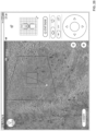
- FIGS. 23-26 are exemplary screen shots of the MAP application showing various map views during the performance of a compaction task.
- FIGS. 23 and 25 show the boundary of the autonomous operating zone and the autonomous path travelled by the compactor during performance of the task (i.e., the actual driven path as opposed to the planned command path).
- FIG. 23 additionally shows an obstacle preview for an obstacle detected by the environmental sensors of the compactor when travelling along the command path (see the upper right corner of the display, which indicates that an obstacle is located a distance of 1.671 feet from the compactor).
- FIG. 24 shows a 3D view of the compactor and surrounding terrain, which can be generated by pressing the two-way expanding arrows in the lower right corner of the obstacle preview.
- FIG. 26 shows an elevation heatmap for the autonomous operating zone during performance of the task. It should be noted that one or any combination of the autonomous path, the command path, and the elevation heatmap may be displayed, as selected through the settings menu shown in FIGS. 25 and 26 .
- FIGS. 27-28 are exemplary screen shots of the MAP application showing various map views during the performance of a point-to-point travel task.
- FIG. 27 shows a command path for the compactor during performance of the task.
- FIG. 28 shows a command path for the compactor while avoiding an exclusion zone during performance of the task.
- the vehicle can continue to perform the task. In some embodiments, if communications are not re-established within a configurable time period, the vehicle pauses task execution until communications are re-established.
- the autonomous operating zone and command path are stored in robotics processing unit 110, which will enable computing device 126 to receive the current map data when communications are re-established.
- another computing device connects to robotics processing unit110 (or to a master node from a vehicle cluster/swarm, as discussed below), that computing device will also receive the current map data.
- the main menu of the MAP application includes directional buttons in the lower right corner of the screen that function as a joystick to the actual compactor. These directional buttons enable a user to drive the compactor forward and reverse and also adjust the driven body angle.
- the MAP application enables both autonomous and manual operation of the compactor.
- FIG. 11A illustrates the front and rear compartments of the vehicle as connected by an articulating joint, as well as the following lines: line a is the zero body angle heading (i.e., the heading that the vehicle would move if perfectly straight); line b is the front vector; line c is the rear vector; and line d is the line from the articulated joint to waypoint A.
- line a is the zero body angle heading (i.e., the heading that the vehicle would move if perfectly straight);
- line b is the front vector;
- line c is the rear vector;
- line d is the line from the articulated joint to waypoint A.
- angle C is the body angle between the front vector b and the rear vector c
- angle D is the front line-of-sight angle between the front vector b and the waypoint line d
- angle E is the rear line-of-sight angle between the rear vector c and the waypoint line d
- angle F is the zero body angle heading forward
- angle G is the zero body angle heading reverse.
- the vehicle control process begins at step 1100.
- the angles shown in FIG. 11A i.e., angles C, D, E, F and G
- the turn and throttle command is initialized to 0.
- step 1108 it is determined whether the zero body angle heading forward (i.e., angle F) is greater than an end shuffle turn threshold (typically 4 degrees in this embodiment). If not, the shuffle turn is ended in step 1110. If so, it is determined whether the vehicle is in a turn state in step 1112 and, if not, whether the vehicle is in a drive state in step 1114.
- angle F the zero body angle heading forward
- end shuffle turn threshold typically 4 degrees in this embodiment
- step 1109 it is determined whether the zero body angle heading reverse (i.e., angle G) is greater than an end shuffle turn threshold (typically 4 degrees in this embodiment). If not, the shuffle turn is ended in step 1110. If so, it is determined whether the vehicle is in a turn state in step 1112 and, if not, whether the vehicle is in a drive state in step 1114.
- an end shuffle turn threshold typically 4 degrees in this embodiment
- step 1112 it is determined whether the body angle command has been achieved in step 1126. If so, the vehicle is set to a drive state in step 1128. If not, the turn command is set to right or left, as applicable, in step 1130. In either case, the process proceeds to step 1154.
- step 1116 If the vehicle is in a drive state in step 1114, then it is determined in step 1116 whether the drive countdown is less than a drive time limit (typically 2 seconds in this embodiment). If not, then the turn state and body angle command is set in step 1118. If so, then it is determined whether the vehicle is moving forward in step 1120. If not, then the throttle command is set to reverse in step 1122. If so, then the throttle command is set to forward in step 1124 and the process proceed to step 1154.
- a drive time limit typically 2 seconds in this embodiment
- step 1132 it is determined in step 1132 whether the zero body angle heading reverse (angle G) is less than the zero body angle heading forward (angle F). If not, then the vehicle is set to forward in step 1134. If so, then the vehicle is set to reverse in step 1136. In step 1138, it is determined whether the zero body angle heading reverse (angle G) is less than a shuffle turn threshold (typically 20 degrees in this embodiment). If not, the shuffle turn is active in set 1140. If so, then in step 1142, it is determined whether the absolute value of the body angle (angle C) is less than a throttle threshold (typically 15 degrees in this embodiment).
- a throttle threshold typically 15 degrees in this embodiment
- step 1144 determines whether the body angle (angle C) is greater than zero. If so, then the turn command is set to right in step 1148 and the process proceeds to step 1154. If not, then the turn command is set to left in step 1146 and the process proceeds to step 1154.
- step 1142 if it is determined that the absolute value of the body angle (angle C) is less than the throttle threshold, then the throttle command is set to reverse or forward, as applicable, in step 1150.
- step 1152 it is determined whether the rear line-of-sight angle (angle E) is greater than a turn threshold (typically 1 degree in this embodiment). If so, then the turn command is set to right in step 1148 and the process proceeds to step 1154. If not, then the turn command is set to left in step 1146 and the process proceeds to step 1154.
- a turn threshold typically 1 degree in this embodiment
- step 1154 it is determined whether the throttle command is forward. If so, then it is determined in step 1159 whether the obstacle distance front is greater than an obstacle threshold (typically 1 meter in this embodiment). If not, the throttle and turn commands are sent to the vehicle control unit at step 1162. If so, the throttle command and turn is set to idle in step 1160, and then the throttle and turn commands are sent to the vehicle control unit at step 1162.
- an obstacle threshold typically 1 meter in this embodiment
- step 1156 If the throttle command is not forward in step 1154, then it is determined in step 1156 whether the throttle command is reverse. If so, then it is determined in step 1158 whether the obstacle distance rear is greater than an obstacle threshold (typically 1 meter in this embodiment). If not, the throttle and turn commands are sent to the vehicle control unit at step 1162. If so, the throttle command and turn is set to idle in step 1160, and then the throttle and turn commands are sent to the vehicle control unit at step 1162.
- an obstacle threshold typically 1 meter in this embodiment
- a method for detecting an obstacle in the vehicle's path is shown as reference numeral 1200. It should be understood that this method is performed by the obstacle detection process of robotics processing unit 110.
- a point cloud is received from a sensor (e.g., 3D depth camera 122 mounted on front bumper 206 of compactor 200) or generated from a combination of sensors and defined via a sensor fusion algorithm.
- the points in the point cloud are filtered to only return points above or below one or more predefined thresholds.
- the filtered points are sorted along the x-axis from the point closest to the vehicle to the point further from the vehicle.
- the first sorted point is selected in step 1208 and, in step 1210, the points located within a predefined radius (typically 2 centimeters in this embodiment) of the selected point are identified.
- step 1212 it is determined whether the number of identified points is greater than a predefined threshold. If so, it is determined that an obstacle has been detected and a rectangle containing all of the filtered points is calculated in step 1216. Then, in step 1218, the world position of the rectangle (which is representative of the obstacle) is calculated and a new obstacle message is sent to the map process of robotics processing unit 110 for comparison to the grid.
- an exclusion zone is defined dynamically by the vehicle itself during operation of a task, e.g., when an obstacle is detected by the environmental sensors.
- step 1214 If the number of identified points is not greater than a predefined threshold in step 1212, then the next sorted point is selected in step 1214. Steps 1210 and 1212 are then repeated for each selected point until a point is located that has the required number of points located within the predefined radius, indicating that an obstacle has been detected. A rectangle containing all of the filtered points is then calculated in step 1216 and, in step 1218, the world position of the rectangle is calculated and a new obstacle message is sent to the map process of robotics processing unit 110, as described above. If no point has the required number of points located within the predefined radius, then it is determined that an obstacle is not detected.
- Any user may trigger an emergency stop of one or more vehicles operating in autonomous mode by selecting the E-Stop button provided on the display of the user's computing device.
- the exemplary screen shots shown in FIGS. 20-28 illustrate the E-Stop button displayed on computing device 126.
- the E-Stop button may also be provided on smaller displays, such as the display of computing device 128.
- the emergency stop message causes the vehicle to enter a designated safe state, typically engine off and brake engaged.
- the vehicle controller process sets the emergency stop status to stopped (Set Estop Status).
- the vehicle controller process then transmits the updated status (Emergency Stop Status) to the emergency cloud service, which transmits an updated map message (Map Client Update) or an updated vehicle status message (Vehicle Status Update) to the MAP application of each computing device.
- the MAP application checks whether the emergency stop has been enabled (Check Estop Enabled) and continues to send emergency stop broadcast messages (Emergency Stop Broadcast) until the status of the vehicle shows as being stopped.
- the emergency cloud service resides on the LTE network and the user is authenticated with JSON web tokens and identified through one or more vehicles that are assigned to that user through an equipment rental platform, such as the platform described in U.S. Patent Application Publication No. US2020/0043262 titled "Method, System and Apparatus for Equipment Monitoring and Access Control" Of course, other user authentication protocols may also be used.
- the emergency cloud service Upon authentication of the user, the emergency cloud service transmits an emergency stop disable message (Emergency Stop Disable) to the vehicle controller process of robotics processing node 110 so that the vehicle can be restarted to resume operation.
- the vehicle controller process sets the emergency stop status to operating (Set Estop Status) and transmits the updated status (Emergency Stop Status) to the emergency cloud service, which transmits an updated map message (Map Client Update) or an updated vehicle status message (Vehicle Status Update) to the MAP application of each computing device.
- robotics processing unit 1500 includes a data manager 1510 connected via the cloud 1526 that receives peripheral vehicle details provided by the web API of an equipment rental platform (e.g., the platform described in U.S. Patent Application Publication No. US2020/0043262 titled "Method, System and Apparatus for Equipment Monitoring and Access Control").
- data manager 1510 receives information on whether each of vehicles 1518a-1518n is available or has been assigned to a particular user and then stores that information in a database 1508.
- Cloud 1526 may also provide remote storage of logs pertaining to system data that can be used to restore system state and provide post action reporting to the user.
- the system also includes a MAP application 1520 executed on a computing device that interfaces with the client interface process 1506 of robotics processing unit 1500. Only one computing device with a MAP application 1520 is shown in FIG. 15A , although multiple computing devices may be used at a single work site.
- the MAP application 1520 is configured to present on the display of the computing device any vehicle with a GPS sensor that is monitored and controlled by the rental platform when the vehicle is in a viewable radius.
- the MAP application enables a user to select a particular vehicle for control and operation, e.g., a vehicle from the list of available vehicles presented on the display of the computing device. In some embodiments, a vehicle is presented for selection only when the vehicle is not currently executing a task defined by a computing device.
- the computing device may issue commands to multiple vehicles, but typically any given vehicle is permitted to execute only a single task from a single computing device at a time. Vehicles that are not currently available for task assignment may be presented on the computing device, but selection of any such vehicle only permits the computing device to monitor (i.e., observe) the vehicle, rather than issue commands to the vehicle.
- the computing device may, however, be enabled to issue emergency stop commands to vehicles being monitored, as described below.
- the system also includes a sensor mast system 1516 configured to track all moving vehicles at the work site.
- the sensor mast system is comprised of a LiDAR camera and radar sensor suite that is capable of tracking larger obstacles up to 300 meters.
- Robotics processing unit 1500 implements a sensor fusion process 1512 that fuses the sensor data received from sensor mast system 1516 and provides the data to the map process 1502.
- the system provides any MAP application-controlled autonomous vehicle with knowledge about the position of other vehicles on the site so that it can pause operations if another vehicle approaches within a predetermined radius.
- the system further provides an emergency stop service 1514 that enables a user to implement an emergency stop for one or all of vehicles 1518a-1518n.
- a computing device 1522 may transmit the emergency stop message directly to emergency stop service 1514 over the local WiFi network at the work site.
- Computing device 1522 may also transmit the emergency stop message over the LTE network to a third party emergency cloud service 1524, which broadcasts the emergency stop message to local emergency stop service 1514.
- Computing device 1522 may comprise a computing device that implements MAP application 1520, or may be part of a third party system.
- multiple computing devices will typically be able to transmit emergency stop messages to emergency stop services 1514. It should be understood that the functionality of emergency stop service 1514 is similar to that described above in connection with FIG. 13 .
- the system may operate in a swarm mode in which multiple vehicles can work together to complete a variety of tasks. For each vehicle, the user may select a task and the system will plan the path for each of the multiple vehicles.
- the vehicles may be of the same type, or the vehicles may be of different types to enable completion of, for example, compaction, grading, and pad preparation tasks.
- the elevation heatmap for a particular vehicle may trigger the generation of a new task for another vehicle. For example, if a compactor's elevation heatmap shows areas of low elevation, a new task may be triggered for a skid loader to deliver more aggregate to that area for further compaction.
- the types of vehicles that may be operated in swarm mode will be apparent to those skilled in the art.
- FIG. 15B another embodiment of a system for enabling autonomous or semi-autonomous operation of multiple vehicles or other machines is shown.
- one vehicle operates as a master vehicle with a robotics processing unit 1530 that enables centralized tracking and control of multiple slave vehicles 1540a ... 1540n.
- the number of vehicles that may be tracked and controlled by the master vehicle is typically in the range of 2-25 vehicles, although the system is scalable to support over 100 vehicles.
- Each of vehicles 1540a-1540n includes most of the components shown in FIG. 1 , with the exception that the map, path planning and client interface processes of robotics processing unit 110 (see FIG.
- the system also includes a MAP application 1538 executed on a computing device that interfaces with the client interface process 1532 of robotics processing unit 1530. Only one computing device with a MAP application 1538 is shown in FIG. 15B , although multiple computing devices may be used at a single work site.
- the MAP application 1538 is configured to present on the display of the computing device one or more vehicles and enable a user to select a particular vehicle for control and operation. In some embodiments, a vehicle is presented for selection only when the vehicle is not currently executing a task defined by a computing device.
- the computing device may issue commands to multiple vehicles, but typically any given vehicle is permitted to execute only a single task from a single computing device at a time.
- Vehicles that are not currently available for task assignment may be presented on the computing device, but selection of any such vehicle only permits the computing device to monitor (i.e., observe) the vehicle, rather than issue commands to the vehicle.
- the computing device may, however, be enabled to issue emergency stop commands to vehicles being monitored.
- FIG. 16 a method for enabling autonomous or semi-autonomous operation of multiple vehicles using either the system of FIG. 15A or the system of FIG. 15B is shown.
- the steps of this method are performed by different components of each system, including the MAP application 1520 of a computing device as shown in FIG. 15A or the MAP application 1538 of a computing device as shown in FIG. 15B ("MAP"), the client interface process 1506 of central robotics processing node 1500 shown in FIG. 15A or the client interface process 1532 of robotics processing node 1530 shown in FIG. 15B (“Client”), the map process 1502 of central robotics processing node 1500 shown in FIG. 15A or the map process 1536 of robotics processing node 1530 shown in FIG.
- MAP MAP application
- Client the client interface process 1506 of central robotics processing node 1500 shown in FIG. 15A or the client interface process 1532 of robotics processing node 1530 shown in FIG. 15B
- the navigation process of each vehicle sends registration information (Register) to the central map process.
- a MAP application of a computing device sends a map update (Map Update) to the central client interface
- the central client interface transmits the map update (Map Update) to the central map process.
- the central map process returns a map object (Map Object) to the central client interface, which transmits the map update to the MAP application of the computing device (and the MAP application of each other computing device connected to the system).
- the user uses the MAP application to select a vehicle (Select Vehicle).
- the MAP application Upon selection of the vehicle, the MAP application transmits a unique vehicle identifier for the selected vehicle and a unique user identifier (Control Configuration) to the central client interface process.
- the MAP application also transmits control commands such as the joystick inputs, engine state, vibration state, autonomous mode state or any other controllable functionality on a vehicle (Control Commands) to the central client interface process, which transmits those control commands (Control Commands) to the vehicle controller process of the selected vehicle.
- the vehicle observer process of the selected vehicle transmits status updates (Status Updates) to the central client interface process, which transmits those status updates (Status Updates) to the MAP application.
- the MAP application transmits the boundary configuration (Boundary) to the central client interface process, which transmits the boundary configuration (Boundary) to the central map process for generation of a map with the defined boundaries. Also, when a user submits a coverage task, the MAP application transmits the task type and/or task details (Task) to the central client interface process, which transmits the task type and/or task details (Task) to the central map process. It can be appreciated that the task types and task details will be dependent on the nature and capabilities of the vehicle.
- the central map process then creates the autonomous task and transmits a command path generated by the central path planning process ("Command Path) to the navigation process of the selected vehicle.
- the MAP application transmits an emergency stop message (E-Stop) to the central client interface process, which transmits the emergency stop message (E-Stop) to the vehicle controller process of the selected vehicle.
- E-Stop an emergency stop message
- the emergency stop message may also be transmitted to other vehicles operating at the work site, as described above.
- Other details relating to the messages shown in FIG. 16 will be apparent to those skilled in the art based on the disclosure provided herein.
Landscapes
- Engineering & Computer Science (AREA)
- Radar, Positioning & Navigation (AREA)
- Remote Sensing (AREA)
- Physics & Mathematics (AREA)
- Automation & Control Theory (AREA)
- General Physics & Mathematics (AREA)
- Aviation & Aerospace Engineering (AREA)
- General Engineering & Computer Science (AREA)
- Structural Engineering (AREA)
- Civil Engineering (AREA)
- Mining & Mineral Resources (AREA)
- Acoustics & Sound (AREA)
- Electromagnetism (AREA)
- Control Of Position, Course, Altitude, Or Attitude Of Moving Bodies (AREA)
- Navigation (AREA)
- Manipulator (AREA)
- Selective Calling Equipment (AREA)
- Traffic Control Systems (AREA)
Claims (15)
- Ein System zum autonomen oder halbautonomen Betrieb eines Fahrzeugs, Folgendes beinhaltend:eine Maschinenautomationsportal(MAP)-Anwendung, die konfiguriert ist, um auf einer Rechenvorrichtung (126, 128) ausgeführt zu werden, wobei die MAP-Anwendung konfiguriert ist, um der Rechenvorrichtung Folgendes zu ermöglichen:(a) Anzeigen einer Karte einer Baustelle; und(b) Bereitstellen einer grafischen Benutzerschnittstelle, die einem Benutzer Folgendes ermöglicht: (i) Definieren einer Begrenzung einer autonomen Betriebszone auf der angezeigten Karte, wobei die Begrenzung der autonomen Betriebszone auf der angezeigten Karte abgebildet wird, (ii) Definieren einer Begrenzung einer oder mehrerer Sperrzonen auf der angezeigten Karte, wobei die Begrenzung jeder Sperrzone auf der angezeigten Karte abgebildet wird, und (iii) Definieren einer von dem Fahrzeug durchzuführenden Zielaufgabe, die einen Aufgabentyp für das Fahrzeug und ein oder mehrere Aufagbendetails umfasst;(c) wobei die grafische Benutzerschnittstelle es dem Bediener ferner ermöglicht, eine oder beide der Begrenzung der autonomen Betriebszone und der Begrenzung jeder Sperrzone auf der angezeigten Karte zu verändern; undeine Robotikverarbeitungseinheit (110), die für Folgendes konfiguriert ist: (a) Empfangen, von der Rechenvorrichtung (126, 128) über eine drahtlose Kommunikationsverbindung, der Begrenzung der autonomen Betriebszone, der Begrenzung jeder Sperrzone und der Zielaufgabe, (b) Erzeugen eines geplanten Befehlswegs, den das Fahrzeug zurücklegen wird, um die Zielaufgabe innerhalb der Begrenzung der autonomen Betriebszone unter Vermeidung jeder Sperrzone durchzuführen, (c) Übertragen, an die Rechenvorrichtung über die drahtlose Kommunikationsverbindung, einer Kartenaktualisierung mit dem geplanten Befehlsweg, wobei die grafische Benutzerschnittstelle der MAP-Anwendung es dem Bediener ferner ermöglicht, den geplanten Befehlsweg auf der angezeigten Karte zu betrachten, (d) Empfangen, von der Rechenvorrichtung über die drahtlose Kommunikationsverbindung, einer Angabe, mit der Zielaufgabe zu beginnen, und (e) Steuern des Betriebs des Fahrzeugs, sodass das Fahrzeug den geplanten Befehlsweg zurücklegt, um die Zielaufgabe durchzuführen.
- System gemäß Anspruch 1, wobei die Rechenvorrichtung (126, 128) eines von einem Personal-Computing-Tablet, einem Smartphone, einer Smartwatch, einer tragbaren Vorrichtung, einem Personal-Computer, einem Laptop-Computer, einem Personal-Digital-Assistant, Smartglasses oder einem Virtual-Reality(VR)-Head-Set beinhaltet.
- System gemäß Anspruch 1 oder 2, wobei das Fahrzeug eines von einem Grabenwalzenverdichter, einem Kompaktlader, einem Bagger, einem Muldenkipper/Dumper, einem Mäher, einer Straßenkehrmaschine, einer Schneefräse, einem Schneepflug, einem Schürfzug oder einem Straßenfertiger beinhaltet.
- System gemäß einem der Ansprüche 1-3, wobei sich die Robotikverarbeitungseinheit (110) auf dem Fahrzeug befindet.
- System gemäß einem der Ansprüche 1-3, wobei sich die Robotikverarbeitungseinheit (110) von dem Fahrzeug entfernt befindet.
- System gemäß Anspruch 5, wobei sich die Robotikverarbeitungseinheit (110) auf entweder (i) einem zentralen Baustellensteuerungssystem, das eine Vielzahl von Fahrzeugen steuert, oder (ii) einem Master-Fahrzeug, das eine Vielzahl von Slave-Fahrzeugen steuert, befindet.
- System gemäß einem der Ansprüche 1-6, wobei die grafische Benutzerschnittstelle der MAP-Anwendung es dem Bediener ermöglicht, die Begrenzung der autonomen Betriebszone durch Platzieren einer Vielzahl von Begrenzungsmarkern auf der angezeigten Karte zu definieren, wobei die MAP-Anwendung konfiguriert ist, um Linien zum Verbinden der Begrenzungsmarker innerhalb der grafischen Benutzerschnittstelle zu ziehen, um dadurch die Begrenzung der autonomen Betriebszone auf der angezeigten Karte abzubilden.
- System gemäß einem der Ansprüche 1-6, wobei die grafische Benutzerschnittstelle der MAP-Anwendung es dem Bediener ermöglicht, die Begrenzung der autonomen Betriebszone durch Gehen entlang eines beabsichtigten Wegs der Begrenzung zu definieren, während die Rechenvorrichtung gleichzeitig eine Vielzahl von GPS-Koordinaten überträgt, um eine Vielzahl von Begrenzungsmarkern auf der angezeigten Karte zu definieren, wobei the MAP-Anwendung konfiguriert ist, um Linien zum Verbinden der Begrenzungsmarker innerhalb der grafischen Benutzerschnittstelle zu ziehen, um dadurch die Begrenzung der autonomen Betriebszone auf der angezeigten Karte abzubilden.
- System gemäß Anspruch 7 oder 8, wobei die grafische Benutzerschnittstelle der MAP-Anwendung es dem Bediener ermöglicht, die Begrenzung der autonomen Betriebszone durch individuelles Einstellen jedes der Begrenzungsmarker auf der angezeigten Karte zu verändern.
- System gemäß einem der Ansprüche 1-9, wobei die grafische Benutzerschnittstelle der MAP-Anwendung es dem Bediener ferner ermöglicht, die Angabe, mit der Zielaufgabe zu beginnen, einzugeben.
- System gemäß einem der Ansprüche 1-10, wobei die Robotikverarbeitungseinheit (110) ferner konfiguriert ist, um den tatsächlichen autonomen Weg, den das Fahrzeug zurückgelegt hat, um die Zielaufgabe innerhalb der autonomen Betriebszone durchzuführen, zu bestimmen und eine Kartenaktualisierung mit dem tatsächlichen autonomen Weg über die drahtlose Kommunikationsverbindung an die Rechenvorrichtung zu übertragen, und wobei die grafische Benutzerschnittstelle der MAP-Anwendung es dem Bediener ferner ermöglicht, den tatsächlichen autonomen Weg auf der angezeigten Karte zu betrachten.
- System gemäß einem der Ansprüche 1-11, wobei das Fahrzeug mindestens einen Sensor beinhaltet, der konfiguriert ist, um Sensordaten zu sammeln, und wobei die Robotikverarbeitungseinheit (110) konfiguriert ist, um die Sensordaten zu verwenden, um bei der Durchführung der Zielaufgabe innerhalb der autonomen Betriebszone ein Hindernis auf dem geplanten Befehlsweg des Fahrzeugs zu erkennen.
- System gemäß Anspruch 12, wobei der Sensor eine dreidimensionale Tiefenkamera oder einen oder mehrere Ultraschallsensoren beinhaltet.
- System gemäß Anspruch 12 oder 13, wobei die Robotikverarbeitungseinheit (110) ferner konfiguriert ist, um eine Kartenaktualisierung mit dem erkannten Hindernis über die drahtlose Kommunikationsverbindung an die Rechenvorrichtung zu übertragen, und wobei die grafische Benutzerschnittstelle der MAP-Anwendung es dem Bediener ferner ermöglicht, das erkannte Hindernis auf der angezeigten Karte zu betrachten.
- System gemäß Anspruch 14, wobei die grafische Benutzerschnittstelle der MAP-Anwendung es dem Bediener ferner ermöglicht, das erkannte Hindernis von der angezeigten Karte zu entfernen.
Applications Claiming Priority (3)
| Application Number | Priority Date | Filing Date | Title |
|---|---|---|---|
| US201962829986P | 2019-04-05 | 2019-04-05 | |
| US202062987062P | 2020-03-09 | 2020-03-09 | |
| PCT/US2020/026877 WO2020206426A1 (en) | 2019-04-05 | 2020-04-06 | System and method for autonomous operation of a machine |
Publications (4)
| Publication Number | Publication Date |
|---|---|
| EP3948472A1 EP3948472A1 (de) | 2022-02-09 |
| EP3948472A4 EP3948472A4 (de) | 2022-12-07 |
| EP3948472B1 true EP3948472B1 (de) | 2024-10-02 |
| EP3948472B8 EP3948472B8 (de) | 2024-11-06 |
Family
ID=72666295
Family Applications (1)
| Application Number | Title | Priority Date | Filing Date |
|---|---|---|---|
| EP20782411.1A Active EP3948472B8 (de) | 2019-04-05 | 2020-04-06 | System und verfahren zum autonomen betrieb einer maschine |
Country Status (7)
| Country | Link |
|---|---|
| US (9) | US11079755B2 (de) |
| EP (1) | EP3948472B8 (de) |
| AU (7) | AU2020254819B2 (de) |
| CA (4) | CA3136140C (de) |
| MX (8) | MX394235B (de) |
| NZ (2) | NZ781816A (de) |
| WO (1) | WO2020206426A1 (de) |
Families Citing this family (51)
| Publication number | Priority date | Publication date | Assignee | Title |
|---|---|---|---|---|
| JP7404170B2 (ja) * | 2020-06-25 | 2023-12-25 | 株式会社小松製作所 | 作業機械の方位を較正するためのシステムおよび方法 |
| US11774959B2 (en) * | 2020-07-30 | 2023-10-03 | Caterpillar Paving Products Inc. | Systems and methods for providing machine configuration recommendations |
| US11236492B1 (en) * | 2020-08-25 | 2022-02-01 | Built Robotics Inc. | Graphical user interface for real-time management of an earth shaping vehicle |
| JP7044949B1 (ja) * | 2020-09-11 | 2022-03-30 | 日本国土開発株式会社 | 建設機械 |
| DE102020211960A1 (de) * | 2020-09-24 | 2022-03-24 | Ford Global Technologies, Llc | Kartierung eines befahrbaren Bereiches |
| CN118898739A (zh) * | 2020-11-06 | 2024-11-05 | 北京石头创新科技有限公司 | 一种识别障碍物的方法、装置、介质和电子设备 |
| JP7718810B2 (ja) * | 2020-12-02 | 2025-08-05 | ヤンマーホールディングス株式会社 | 自動走行システム、自動走行方法、及び自動走行プログラム |
| SE544667C2 (en) * | 2020-12-08 | 2022-10-11 | Husqvarna Ab | A robotic work tool with a re-definable operation area |
| US20220187823A1 (en) * | 2020-12-15 | 2022-06-16 | Caterpillar Inc. | Methods and systems for dynamic geofencing |
| DE102020133610A1 (de) | 2020-12-15 | 2022-06-15 | Liebherr-Werk Bischofshofen Gmbh | Vorrichtung und Verfahren zum sicheren Interagieren von unbemannten Lademaschinen und bemannten Fahrzeugen und Personen |
| FI20206380A1 (en) * | 2020-12-29 | 2022-06-30 | Novatron Oy | A method for compacting the soil and a soil compactor |
| JP7076020B1 (ja) | 2021-02-02 | 2022-05-26 | 日立建機株式会社 | 自動作業システム |
| US20220259822A1 (en) * | 2021-02-18 | 2022-08-18 | Caterpillar Inc. | Automated Mobilization of Mobile Machines |
| US11906952B2 (en) * | 2021-02-19 | 2024-02-20 | Joy Global Surface Mining Inc | System and method for operating a mining machine with respect to a geofence using a dynamic operation zone |
| US12296694B2 (en) | 2021-03-10 | 2025-05-13 | Techtronic Cordless Gp | Lawnmowers |
| DE102021002728A1 (de) * | 2021-05-26 | 2022-12-01 | Bomag Gmbh | Verfahren zum steuern des fahrbetriebs einer selbstfahrenden bodenverdichtungsmaschine und bodenverdichtungsmaschine |
| US12065788B2 (en) | 2021-06-23 | 2024-08-20 | Caterpillar Paving Products Inc. | System and method for marking a boundary while defining an autonomous worksite |
| US20230067916A1 (en) * | 2021-08-25 | 2023-03-02 | Zachary Liollio | Methods and systems for construction implement management |
| US11778935B2 (en) | 2021-09-13 | 2023-10-10 | Deere & Company | Controlling operating envelope for off-road equipment based on a digital fence |
| US12443180B2 (en) | 2021-11-10 | 2025-10-14 | Techtronic Cordless Gp | Robotic lawn mowers |
| US20230150358A1 (en) * | 2021-11-18 | 2023-05-18 | Caterpillar Inc. | Collision avoidance system and method for avoiding collision of work machine with obstacles |
| US12460379B2 (en) * | 2021-11-18 | 2025-11-04 | Caterpillar Inc. | Collision avoidance system and method for avoiding collision of work machine with obstacles |
| US12129607B2 (en) * | 2021-11-24 | 2024-10-29 | Caterpillar Paving Products Inc. | Control system and method for defining and generating compactor work area |
| US12072711B2 (en) | 2021-11-30 | 2024-08-27 | Honda Motor Co., Ltd. | Travel route control of autonomous work vehicle using global navigation satellite system |
| EP4194988B1 (de) * | 2021-12-12 | 2024-03-06 | Caterpillar Inc. | System und verfahren zur erzeugung eines arbeitsplans für einen autonomen betrieb eines verdichters |
| AU2023200381A1 (en) | 2022-01-31 | 2023-08-17 | Techtronic Cordless Gp | Robotic garden tool |
| US12110660B2 (en) * | 2022-02-24 | 2024-10-08 | Caterpillar Inc. | Work machine 3D exclusion zone |
| US11997561B2 (en) | 2022-04-07 | 2024-05-28 | Caterpillar Paving Products Inc. | System and method for defining an area of a worksite |
| EP4270138A1 (de) | 2022-04-28 | 2023-11-01 | Techtronic Cordless GP | Erzeugung einer virtuellen grenze für ein robotisches gartenwerkzeug |
| US12472611B2 (en) | 2022-05-31 | 2025-11-18 | Techtronic Cordless Gp | Peg driver |
| CN119365876A (zh) | 2022-06-08 | 2025-01-24 | 卡特彼勒公司 | 路线图创建系统 |
| WO2024004575A1 (ja) * | 2022-06-28 | 2024-01-04 | 株式会社クボタ | 作業車両、および作業車両の制御方法 |
| AU2023204696A1 (en) | 2022-07-19 | 2024-02-08 | Techtronic Cordless Gp | Display for controlling robotic tool |
| EP4340296B1 (de) | 2022-07-29 | 2025-04-09 | Techtronic Cordless GP | Erzeugung eines kryptoschlüssels für ein robotisches gartenwerkzeug |
| US12422845B2 (en) * | 2022-11-10 | 2025-09-23 | Htc Corporation | Vehicle control system, head-mounted display device, and vehicle control method |
| SE546680C2 (en) * | 2022-11-14 | 2025-01-14 | Husqvarna Ab | Improved operation and installation for a robotic work tool |
| US11822342B1 (en) | 2022-12-21 | 2023-11-21 | Built Robotics Inc. | Obstacle map for autonomous pile driving system |
| US12216468B2 (en) | 2022-12-21 | 2025-02-04 | Built Robotics Inc. | Quality control operation for autonomous pile driving system |
| US12282334B2 (en) * | 2022-12-21 | 2025-04-22 | Built Robotics Inc. | Autonomous pile driver apparatus and method |
| US12305353B2 (en) | 2022-12-21 | 2025-05-20 | Built Robotics Inc. | Pile platforms for autonomous pile driver vehicle |
| US11788247B1 (en) | 2022-12-21 | 2023-10-17 | Built Robotics Inc. | Basket assembly operation for autonomous pile driving system |
| US12129624B2 (en) | 2022-12-21 | 2024-10-29 | Built Robotics Inc. | Pile manipulation tool for autonomous pile driver vehicle |
| USD1044862S1 (en) * | 2023-02-28 | 2024-10-01 | Willand (Beijing) Technology Co., Ltd. | Display screen or portion thereof with graphical user interface |
| CA224868S (en) * | 2023-02-28 | 2024-11-05 | Willand Beijing Tech Co Ltd | Display screen with animated graphical user interface |
| CN116300972B (zh) * | 2023-05-17 | 2023-12-12 | 汇智机器人科技(深圳)有限公司 | 一种机器人作业规划方法、系统及其应用 |
| US12370687B2 (en) * | 2023-07-28 | 2025-07-29 | Omron Corporation | Systems and methods for generating safety zones for autonomous mobile robots |
| WO2025101995A1 (en) * | 2023-11-10 | 2025-05-15 | Radio Systems Corporation | Animal tracking system using high-accuracy positioning |
| US12291834B1 (en) * | 2024-03-25 | 2025-05-06 | Built Robotics Inc. | Vehicle movement modification for autonomous pile driver vehicle |
| US12215477B1 (en) * | 2024-03-25 | 2025-02-04 | Built Robotics Inc. | Pile manipulation for autonomous pile driver vehicle |
| US12180670B1 (en) * | 2024-03-26 | 2024-12-31 | Built Robotics Inc. | Autonomous alignment for a pile driving system |
| US20260015834A1 (en) * | 2024-07-15 | 2026-01-15 | Equipmentshare.Com Inc | Calibration and setup for a machine guidance system |
Family Cites Families (77)
| Publication number | Priority date | Publication date | Assignee | Title |
|---|---|---|---|---|
| US7397363B2 (en) | 1993-06-08 | 2008-07-08 | Raymond Anthony Joao | Control and/or monitoring apparatus and method |
| ZA952853B (en) * | 1994-04-18 | 1995-12-21 | Caterpillar Inc | Method and apparatus for real time monitoring and co-ordination of multiple geography altering machines on a work site |
| US5660246A (en) | 1995-11-09 | 1997-08-26 | Products Research, Inc. | Vehicle access controller |
| US5965954A (en) | 1997-09-25 | 1999-10-12 | Johnson Controls Technology Company | Anti-theft system for disabling a vehicle engine |
| DE69922149D1 (de) | 1999-02-26 | 2004-12-30 | Inova Designs Ltd | Fahrzeugbenutzungskontrolle und Sicherheitsvorrichtung |
| DE19912748A1 (de) | 1999-03-22 | 2000-11-02 | Bosch Gmbh Robert | Vorrichtung und Verfahren zur Wiedergabe von Information in einem Kraftfahrzeug |
| US6570486B1 (en) | 1999-04-09 | 2003-05-27 | Delphi Automotive Systems | Passive remote access control system |
| US6571218B1 (en) | 1999-04-14 | 2003-05-27 | Ncr Corporation | Remote approval system and methods for use in network of retail checkout terminals |
| US7356494B2 (en) | 1999-05-19 | 2008-04-08 | I.D. Systems, Inc. | Robust wireless communications system architecture and asset management applications performed thereon |
| DE19929766C1 (de) | 1999-06-29 | 2001-03-22 | Wacker Werke Kg | Typenschild mit Speichereinrichtung |
| US6496107B1 (en) | 1999-07-23 | 2002-12-17 | Richard B. Himmelstein | Voice-controlled vehicle control system |
| EP1272954A4 (de) | 2000-02-16 | 2004-08-18 | Zipcar Inc | Systeme und verfahren zum steuern des fahrzeugzugangs |
| US8032278B2 (en) | 2000-05-17 | 2011-10-04 | Omega Patents, L.L.C. | Vehicle tracking unit with downloadable codes and associated methods |
| US6351703B1 (en) | 2000-06-06 | 2002-02-26 | Detroit Diesel Corporation | Engine control with programmable automatic starting |
| GB2373614B (en) | 2001-03-21 | 2004-11-10 | Int Computers Ltd | Vehicle security system and method |
| DE60225772T2 (de) | 2001-04-05 | 2009-05-14 | Hitachi Construction Machinery Co., Ltd. | Diebstahlsicherungssystem für baumaschinen |
| US6434462B1 (en) * | 2001-06-28 | 2002-08-13 | Deere & Company | GPS control of a tractor-towed implement |
| US20030023453A1 (en) | 2001-07-30 | 2003-01-30 | Centershift | System and method for managing a plurality of rental facilities |
| SG114505A1 (en) | 2001-10-17 | 2005-09-28 | First Cube Pte Ltd | System and method for facilitating delivery and return service |
| JP4078087B2 (ja) | 2002-02-04 | 2008-04-23 | 株式会社東海理化電機製作所 | 電子キーシステム |
| AU2002259103A1 (en) | 2002-05-02 | 2003-11-17 | Lifestream Technologies, Inc. | Computerized information processing and retrieval system |
| US7083090B2 (en) | 2002-08-09 | 2006-08-01 | Patrick Zuili | Remote portable and universal smartcard authentication and authorization device |
| JP4121076B2 (ja) | 2002-12-24 | 2008-07-16 | 富士通テン株式会社 | 遠隔始動制御装置、及び始動制御装置 |
| JP2004280706A (ja) | 2003-03-18 | 2004-10-07 | Toshiba Tec Corp | 端末情報登録装置、端末情報登録方法、および端末情報登録プログラム |
| US9002565B2 (en) | 2003-03-20 | 2015-04-07 | Agjunction Llc | GNSS and optical guidance and machine control |
| US20040189439A1 (en) | 2003-03-28 | 2004-09-30 | Cansino Juan Miguel Dominguez | Local and remote management of lock systems from a network |
| US20040214600A1 (en) | 2003-04-24 | 2004-10-28 | Malvin Schechet | Guest services device |
| US20050179517A1 (en) | 2004-02-17 | 2005-08-18 | Harms Mark R. | Retrofit electronic lock security system |
| DE202004002541U1 (de) | 2004-02-18 | 2005-07-07 | Liebherr-Hydraulikbagger Gmbh | Baumaschine mit Schnellkupplung |
| US20050264396A1 (en) | 2004-05-28 | 2005-12-01 | Caterpillar, Inc. | Machine security system having remote access code management |
| US7844396B2 (en) | 2005-09-13 | 2010-11-30 | Deere & Company | Method and system for modular data processing for a vehicle control system |
| US20070109094A1 (en) | 2005-11-15 | 2007-05-17 | Sahai Anil K | Method and system for dealership keyless entry |
| US7961076B2 (en) | 2006-02-28 | 2011-06-14 | International Business Machines Corporation | Methods and apparatuses for remote control of vehicle devices and vehicle lock-out notification |
| WO2007106875A2 (en) | 2006-03-15 | 2007-09-20 | Qualcomm Incorporated | Digital over-the-air keying system |
| US20070247277A1 (en) | 2006-04-24 | 2007-10-25 | Kenneth Murchison | Electronic or automatic identification method to remotely manage the locks or access points to a multi-compartment secure distribution receptacle, via the internet or wireless communication network |
| JP4259589B2 (ja) | 2006-05-09 | 2009-04-30 | セイコーエプソン株式会社 | 電子機器、アクセス制御方法 |
| US20070289012A1 (en) | 2006-06-13 | 2007-12-13 | Leemon Baird | Remotely controllable security system |
| JP5065387B2 (ja) | 2006-07-10 | 2012-10-31 | コンティネンタル オートモーティブ システムズ ユーエス, インコーポレイティッド | 共通の送信器による量販車両群の制御方法 |
| KR20080029583A (ko) | 2006-09-29 | 2008-04-03 | 두산인프라코어 주식회사 | 건설기계의 도난방지장치 및 그의 동작방법 |
| WO2008044093A1 (en) | 2006-10-11 | 2008-04-17 | Renault Trucks | Customer identification device, keyless access system for vehicle, vehicle sharing system including such a device and methods using such a device |
| US20080281664A1 (en) | 2007-05-07 | 2008-11-13 | David Matthew Campbell | System and method for managing use and availability of equipment |
| US8373581B2 (en) | 2007-06-19 | 2013-02-12 | Magna Electronics, Inc. | Mobile control node system and method for vehicles |
| US20090043462A1 (en) * | 2007-06-29 | 2009-02-12 | Kenneth Lee Stratton | Worksite zone mapping and collision avoidance system |
| US8350670B2 (en) | 2007-07-12 | 2013-01-08 | Kelly Michael P | Methods and systems for secure keyless entry for vehicle fleet management |
| US8410901B2 (en) | 2007-11-12 | 2013-04-02 | Best Lockers, Llc | Assigning controlled access to securable devices |
| US8639408B2 (en) | 2008-10-15 | 2014-01-28 | Deere & Company | High integrity coordination system for multiple off-road vehicles |
| US11155236B2 (en) | 2009-01-15 | 2021-10-26 | Ahern Rentals, Inc. | Method and a system for controlling and monitoring operation of a device |
| US8583326B2 (en) * | 2010-02-09 | 2013-11-12 | Agjunction Llc | GNSS contour guidance path selection |
| US8744626B2 (en) * | 2010-05-27 | 2014-06-03 | Deere & Company | Managing autonomous machines across multiple areas |
| US20110295423A1 (en) | 2010-05-27 | 2011-12-01 | Noel Wayne Anderson | Condition based keep-out for machines |
| US20130155442A1 (en) | 2011-12-19 | 2013-06-20 | Xerox Corporation | Remote management for multi-function devices |
| US20140129301A1 (en) | 2012-11-07 | 2014-05-08 | Ford Global Technologies, Llc | Mobile automotive wireless communication system enabled microbusinesses |
| US9135813B2 (en) | 2012-12-21 | 2015-09-15 | Caterpillar, Inc. | Remote lockout/tagout |
| WO2014183042A1 (en) * | 2013-05-10 | 2014-11-13 | Cnh Industrial America Llc | Control architecture for multi-robot system |
| JP6111179B2 (ja) * | 2013-10-22 | 2017-04-05 | 日立建機株式会社 | ダンプトラックの自律走行システム |
| BR112016011577B1 (pt) | 2013-11-20 | 2021-01-12 | Rowbot Systems Llc | plataforma de veículo autônomo, sistema de plataforma de veículo autônomo, robô agrícola e método para a navegação autônoma de um robô agrícola |
| US9720410B2 (en) * | 2014-03-03 | 2017-08-01 | Waymo Llc | Remote assistance for autonomous vehicles in predetermined situations |
| WO2016103066A1 (en) * | 2014-12-23 | 2016-06-30 | Husqvarna Ab | Zone control system for a robotic vehicle |
| JP5973609B1 (ja) * | 2015-03-27 | 2016-08-23 | 本田技研工業株式会社 | 無人作業車の制御装置 |
| US9494439B1 (en) * | 2015-05-13 | 2016-11-15 | Uber Technologies, Inc. | Autonomous vehicle operated with guide assistance of human driven vehicles |
| US11180189B2 (en) | 2015-11-19 | 2021-11-23 | Agjunction Llc | Automated reverse implement parking |
| US10990245B2 (en) * | 2016-01-15 | 2021-04-27 | Caterpillar Paving Products Inc. | Mobile process management tool for paving operations |
| US10448555B2 (en) | 2016-05-27 | 2019-10-22 | Cnh Industrial America Llc | System and method for scouting vehicle mapping |
| US10512204B1 (en) | 2016-07-22 | 2019-12-24 | Ag Leader Technology, Inc. | Heading measurement compensation for GNSS navigation |
| EP3503703B8 (de) | 2016-08-29 | 2023-10-18 | Guss Automation LLC | Robotisches landwirtschaftliches system und verfahren |
| US11651637B2 (en) | 2016-09-21 | 2023-05-16 | Equipmentshare.Com Inc | Method, system and apparatus for equipment monitoring and access control |
| JP6832660B2 (ja) * | 2016-09-26 | 2021-02-24 | ヤンマーパワーテクノロジー株式会社 | 経路生成システム |
| US10775796B2 (en) * | 2017-01-10 | 2020-09-15 | Cnh Industrial America Llc | Aerial vehicle systems and methods |
| US10386836B2 (en) * | 2017-07-07 | 2019-08-20 | Zoox, Inc. | Interactions between vehicle and teleoperations system |
| CN109840448A (zh) | 2017-11-24 | 2019-06-04 | 百度在线网络技术(北京)有限公司 | 用于无人驾驶车辆的信息输出方法和装置 |
| CN109901567B (zh) | 2017-12-08 | 2020-06-23 | 百度在线网络技术(北京)有限公司 | 用于输出障碍物信息的方法和装置 |
| US10747218B2 (en) * | 2018-01-12 | 2020-08-18 | Ford Global Technologies, Llc | Mobile device tethering for remote parking assist |
| EP4571253A3 (de) | 2018-08-08 | 2025-09-24 | The Toro Company | Verfahren zum trainieren eines autonomen fahrzeugs |
| US11163300B2 (en) * | 2018-08-21 | 2021-11-02 | GM Global Technology Operations LLC | Navigating an autonomous vehicle based upon an image from a mobile computing device |
| US20210095978A1 (en) | 2019-09-26 | 2021-04-01 | Uber Technologies, Inc. | Autonomous Navigation for Light Electric Vehicle Repositioning |
| US20210124348A1 (en) | 2019-10-23 | 2021-04-29 | Uber Technologies, Inc. | Autonomous Clustering for Light Electric Vehicles |
| US11402823B2 (en) * | 2019-11-15 | 2022-08-02 | Caterpillar Inc. | System for validating worksites |
-
2020
- 2020-04-06 EP EP20782411.1A patent/EP3948472B8/de active Active
- 2020-04-06 NZ NZ781816A patent/NZ781816A/en unknown
- 2020-04-06 CA CA3136140A patent/CA3136140C/en active Active
- 2020-04-06 CA CA3232590A patent/CA3232590A1/en active Pending
- 2020-04-06 MX MX2021012199A patent/MX394235B/es unknown
- 2020-04-06 CA CA3232598A patent/CA3232598A1/en active Pending
- 2020-04-06 AU AU2020254819A patent/AU2020254819B2/en active Active
- 2020-04-06 WO PCT/US2020/026877 patent/WO2020206426A1/en not_active Ceased
- 2020-04-06 CA CA3220289A patent/CA3220289A1/en active Pending
- 2020-04-06 NZ NZ787784A patent/NZ787784A/en unknown
- 2020-07-27 US US16/939,358 patent/US11079755B2/en active Active
-
2021
- 2021-06-30 US US17/363,575 patent/US11914365B2/en active Active
- 2021-06-30 US US17/363,413 patent/US12072702B2/en active Active
- 2021-06-30 US US17/363,381 patent/US12066824B2/en active Active
- 2021-06-30 US US17/363,116 patent/US12140947B2/en active Active
- 2021-06-30 US US17/363,528 patent/US11841703B2/en active Active
- 2021-06-30 US US17/363,329 patent/US11662723B2/en active Active
- 2021-06-30 US US17/363,460 patent/US11940789B2/en active Active
- 2021-10-04 MX MX2022008836A patent/MX2022008836A/es unknown
- 2021-10-04 MX MX2022008833A patent/MX2022008833A/es unknown
- 2021-10-04 MX MX2022008837A patent/MX2022008837A/es unknown
- 2021-10-04 MX MX2022008832A patent/MX2022008832A/es unknown
- 2021-10-04 MX MX2022008838A patent/MX2022008838A/es unknown
- 2021-10-04 MX MX2022008839A patent/MX2022008839A/es unknown
- 2021-10-04 MX MX2022008835A patent/MX2022008835A/es unknown
-
2022
- 2022-05-02 AU AU2022202920A patent/AU2022202920B2/en active Active
-
2024
- 2024-01-31 US US18/427,995 patent/US12474702B2/en active Active
- 2024-04-09 AU AU2024202262A patent/AU2024202262B2/en active Active
- 2024-04-09 AU AU2024202259A patent/AU2024202259B2/en active Active
- 2024-04-09 AU AU2024202260A patent/AU2024202260A1/en not_active Abandoned
- 2024-04-09 AU AU2024202261A patent/AU2024202261B2/en active Active
-
2025
- 2025-12-18 AU AU2025283553A patent/AU2025283553A1/en active Pending
Also Published As
Similar Documents
| Publication | Publication Date | Title |
|---|---|---|
| EP3948472B1 (de) | System und verfahren zum autonomen betrieb einer maschine | |
| CN108345299A (zh) | 作业车无线管理系统 | |
| JP7349947B2 (ja) | 情報処理装置、作業機械、情報処理方法、情報処理プログラム | |
| CN116859983A (zh) | 应急救援系统和应急救援系统的控制方法 | |
| JP7779192B2 (ja) | 作業支援装置およびこれを備えた作業システム | |
| US20230266754A1 (en) | Work area overlay on operator display | |
| JP2025148677A (ja) | 動作制御方法、動作制御プログラム、及び動作制御システム | |
| WO2023234076A1 (ja) | 表示システムおよび作業車両 | |
| CN120942357A (zh) | 自动行驶方法、自动行驶程序以及自动行驶系统 |
Legal Events
| Date | Code | Title | Description |
|---|---|---|---|
| STAA | Information on the status of an ep patent application or granted ep patent |
Free format text: STATUS: THE INTERNATIONAL PUBLICATION HAS BEEN MADE |
|
| PUAI | Public reference made under article 153(3) epc to a published international application that has entered the european phase |
Free format text: ORIGINAL CODE: 0009012 |
|
| STAA | Information on the status of an ep patent application or granted ep patent |
Free format text: STATUS: REQUEST FOR EXAMINATION WAS MADE |
|
| 17P | Request for examination filed |
Effective date: 20211029 |
|
| AK | Designated contracting states |
Kind code of ref document: A1 Designated state(s): AL AT BE BG CH CY CZ DE DK EE ES FI FR GB GR HR HU IE IS IT LI LT LU LV MC MK MT NL NO PL PT RO RS SE SI SK SM TR |
|
| DAV | Request for validation of the european patent (deleted) | ||
| DAX | Request for extension of the european patent (deleted) | ||
| REG | Reference to a national code |
Ref country code: DE Ref legal event code: R079 Free format text: PREVIOUS MAIN CLASS: G05D0001020000 Ref country code: DE Ref legal event code: R079 Ref document number: 602020038758 Country of ref document: DE Free format text: PREVIOUS MAIN CLASS: G05D0001020000 Ipc: G05D0001000000 |
|
| A4 | Supplementary search report drawn up and despatched |
Effective date: 20221107 |
|
| RIC1 | Information provided on ipc code assigned before grant |
Ipc: E02F 9/08 20060101ALI20221101BHEP Ipc: E02F 9/26 20060101ALI20221101BHEP Ipc: E02F 9/20 20060101ALI20221101BHEP Ipc: G05D 3/12 20060101ALI20221101BHEP Ipc: G05D 1/10 20060101ALI20221101BHEP Ipc: G05D 1/02 20200101ALI20221101BHEP Ipc: G05D 1/00 20060101AFI20221101BHEP |
|
| STAA | Information on the status of an ep patent application or granted ep patent |
Free format text: STATUS: EXAMINATION IS IN PROGRESS |
|
| 17Q | First examination report despatched |
Effective date: 20230629 |
|
| REG | Reference to a national code |
Ref legal event code: R079 Ipc: G05D0001224000 Ref country code: DE Ref legal event code: R079 Ref document number: 602020038758 Country of ref document: DE Free format text: PREVIOUS MAIN CLASS: G05D0001000000 Ipc: G05D0001224000 |
|
| GRAP | Despatch of communication of intention to grant a patent |
Free format text: ORIGINAL CODE: EPIDOSNIGR1 |
|
| STAA | Information on the status of an ep patent application or granted ep patent |
Free format text: STATUS: GRANT OF PATENT IS INTENDED |
|
| RIC1 | Information provided on ipc code assigned before grant |
Ipc: G05D 109/10 20240101ALN20240410BHEP Ipc: G05D 107/90 20240101ALN20240410BHEP Ipc: G05D 105/05 20240101ALN20240410BHEP Ipc: E02F 9/08 20060101ALI20240410BHEP Ipc: E02F 9/26 20060101ALI20240410BHEP Ipc: E02F 9/20 20060101ALI20240410BHEP Ipc: G05D 1/698 20240101ALI20240410BHEP Ipc: G05D 1/648 20240101ALI20240410BHEP Ipc: G05D 1/248 20240101ALI20240410BHEP Ipc: G05D 1/246 20240101ALI20240410BHEP Ipc: G05D 1/229 20240101ALI20240410BHEP Ipc: G05D 1/224 20240101AFI20240410BHEP |
|
| INTG | Intention to grant announced |
Effective date: 20240424 |
|
| GRAS | Grant fee paid |
Free format text: ORIGINAL CODE: EPIDOSNIGR3 |
|
| GRAA | (expected) grant |
Free format text: ORIGINAL CODE: 0009210 |
|
| STAA | Information on the status of an ep patent application or granted ep patent |
Free format text: STATUS: THE PATENT HAS BEEN GRANTED |
|
| GRAT | Correction requested after decision to grant or after decision to maintain patent in amended form |
Free format text: ORIGINAL CODE: EPIDOSNCDEC |
|
| AK | Designated contracting states |
Kind code of ref document: B1 Designated state(s): AL AT BE BG CH CY CZ DE DK EE ES FI FR GB GR HR HU IE IS IT LI LT LU LV MC MK MT NL NO PL PT RO RS SE SI SK SM TR |
|
| REG | Reference to a national code |
Ref country code: GB Ref legal event code: FG4D |
|
| REG | Reference to a national code |
Ref country code: DE Ref legal event code: R081 Ref document number: 602020038758 Country of ref document: DE Owner name: EQUIPMENTSHARE.COM INC, COLUMBIA, US Free format text: FORMER OWNER: EQUIPMENTSHARE.COM INC., COLUMBIA, MO, US |
|
| REG | Reference to a national code |
Ref country code: CH Ref legal event code: PK Free format text: BERICHTIGUNG B8 Ref country code: CH Ref legal event code: EP |
|
| REG | Reference to a national code |
Ref country code: IE Ref legal event code: FG4D |
|
| REG | Reference to a national code |
Ref country code: DE Ref legal event code: R096 Ref document number: 602020038758 Country of ref document: DE |
|
| REG | Reference to a national code |
Ref country code: LT Ref legal event code: MG9D |
|
| REG | Reference to a national code |
Ref country code: NL Ref legal event code: MP Effective date: 20241002 |
|
| REG | Reference to a national code |
Ref country code: AT Ref legal event code: MK05 Ref document number: 1728937 Country of ref document: AT Kind code of ref document: T Effective date: 20241002 |
|
| PG25 | Lapsed in a contracting state [announced via postgrant information from national office to epo] |
Ref country code: NL Free format text: LAPSE BECAUSE OF FAILURE TO SUBMIT A TRANSLATION OF THE DESCRIPTION OR TO PAY THE FEE WITHIN THE PRESCRIBED TIME-LIMIT Effective date: 20241002 |
|
| PG25 | Lapsed in a contracting state [announced via postgrant information from national office to epo] |
Ref country code: NL Free format text: LAPSE BECAUSE OF FAILURE TO SUBMIT A TRANSLATION OF THE DESCRIPTION OR TO PAY THE FEE WITHIN THE PRESCRIBED TIME-LIMIT Effective date: 20241002 |
|
| PG25 | Lapsed in a contracting state [announced via postgrant information from national office to epo] |
Ref country code: PT Free format text: LAPSE BECAUSE OF FAILURE TO SUBMIT A TRANSLATION OF THE DESCRIPTION OR TO PAY THE FEE WITHIN THE PRESCRIBED TIME-LIMIT Effective date: 20250203 Ref country code: IS Free format text: LAPSE BECAUSE OF FAILURE TO SUBMIT A TRANSLATION OF THE DESCRIPTION OR TO PAY THE FEE WITHIN THE PRESCRIBED TIME-LIMIT Effective date: 20250202 Ref country code: HR Free format text: LAPSE BECAUSE OF FAILURE TO SUBMIT A TRANSLATION OF THE DESCRIPTION OR TO PAY THE FEE WITHIN THE PRESCRIBED TIME-LIMIT Effective date: 20241002 |
|
| PG25 | Lapsed in a contracting state [announced via postgrant information from national office to epo] |
Ref country code: FI Free format text: LAPSE BECAUSE OF FAILURE TO SUBMIT A TRANSLATION OF THE DESCRIPTION OR TO PAY THE FEE WITHIN THE PRESCRIBED TIME-LIMIT Effective date: 20241002 |
|
| PG25 | Lapsed in a contracting state [announced via postgrant information from national office to epo] |
Ref country code: BG Free format text: LAPSE BECAUSE OF FAILURE TO SUBMIT A TRANSLATION OF THE DESCRIPTION OR TO PAY THE FEE WITHIN THE PRESCRIBED TIME-LIMIT Effective date: 20241002 |
|
| PG25 | Lapsed in a contracting state [announced via postgrant information from national office to epo] |
Ref country code: ES Free format text: LAPSE BECAUSE OF FAILURE TO SUBMIT A TRANSLATION OF THE DESCRIPTION OR TO PAY THE FEE WITHIN THE PRESCRIBED TIME-LIMIT Effective date: 20241002 |
|
| PG25 | Lapsed in a contracting state [announced via postgrant information from national office to epo] |
Ref country code: NO Free format text: LAPSE BECAUSE OF FAILURE TO SUBMIT A TRANSLATION OF THE DESCRIPTION OR TO PAY THE FEE WITHIN THE PRESCRIBED TIME-LIMIT Effective date: 20250102 |
|
| PG25 | Lapsed in a contracting state [announced via postgrant information from national office to epo] |
Ref country code: LV Free format text: LAPSE BECAUSE OF FAILURE TO SUBMIT A TRANSLATION OF THE DESCRIPTION OR TO PAY THE FEE WITHIN THE PRESCRIBED TIME-LIMIT Effective date: 20241002 Ref country code: AT Free format text: LAPSE BECAUSE OF FAILURE TO SUBMIT A TRANSLATION OF THE DESCRIPTION OR TO PAY THE FEE WITHIN THE PRESCRIBED TIME-LIMIT Effective date: 20241002 Ref country code: GR Free format text: LAPSE BECAUSE OF FAILURE TO SUBMIT A TRANSLATION OF THE DESCRIPTION OR TO PAY THE FEE WITHIN THE PRESCRIBED TIME-LIMIT Effective date: 20250103 |
|
| PG25 | Lapsed in a contracting state [announced via postgrant information from national office to epo] |
Ref country code: PL Free format text: LAPSE BECAUSE OF FAILURE TO SUBMIT A TRANSLATION OF THE DESCRIPTION OR TO PAY THE FEE WITHIN THE PRESCRIBED TIME-LIMIT Effective date: 20241002 Ref country code: CZ Free format text: LAPSE BECAUSE OF FAILURE TO SUBMIT A TRANSLATION OF THE DESCRIPTION OR TO PAY THE FEE WITHIN THE PRESCRIBED TIME-LIMIT Effective date: 20241002 |
|
| PG25 | Lapsed in a contracting state [announced via postgrant information from national office to epo] |
Ref country code: RS Free format text: LAPSE BECAUSE OF FAILURE TO SUBMIT A TRANSLATION OF THE DESCRIPTION OR TO PAY THE FEE WITHIN THE PRESCRIBED TIME-LIMIT Effective date: 20250102 |
|
| PG25 | Lapsed in a contracting state [announced via postgrant information from national office to epo] |
Ref country code: SM Free format text: LAPSE BECAUSE OF FAILURE TO SUBMIT A TRANSLATION OF THE DESCRIPTION OR TO PAY THE FEE WITHIN THE PRESCRIBED TIME-LIMIT Effective date: 20241002 |
|
| REG | Reference to a national code |
Ref country code: DE Ref legal event code: R097 Ref document number: 602020038758 Country of ref document: DE |
|
| PGFP | Annual fee paid to national office [announced via postgrant information from national office to epo] |
Ref country code: DE Payment date: 20250429 Year of fee payment: 6 |
|
| PG25 | Lapsed in a contracting state [announced via postgrant information from national office to epo] |
Ref country code: DK Free format text: LAPSE BECAUSE OF FAILURE TO SUBMIT A TRANSLATION OF THE DESCRIPTION OR TO PAY THE FEE WITHIN THE PRESCRIBED TIME-LIMIT Effective date: 20241002 |
|
| PGFP | Annual fee paid to national office [announced via postgrant information from national office to epo] |
Ref country code: GB Payment date: 20250428 Year of fee payment: 6 |
|
| PGFP | Annual fee paid to national office [announced via postgrant information from national office to epo] |
Ref country code: FR Payment date: 20250425 Year of fee payment: 6 |
|
| PG25 | Lapsed in a contracting state [announced via postgrant information from national office to epo] |
Ref country code: RO Free format text: LAPSE BECAUSE OF FAILURE TO SUBMIT A TRANSLATION OF THE DESCRIPTION OR TO PAY THE FEE WITHIN THE PRESCRIBED TIME-LIMIT Effective date: 20241002 |
|
| PG25 | Lapsed in a contracting state [announced via postgrant information from national office to epo] |
Ref country code: SK Free format text: LAPSE BECAUSE OF FAILURE TO SUBMIT A TRANSLATION OF THE DESCRIPTION OR TO PAY THE FEE WITHIN THE PRESCRIBED TIME-LIMIT Effective date: 20241002 |
|
| PG25 | Lapsed in a contracting state [announced via postgrant information from national office to epo] |
Ref country code: IT Free format text: LAPSE BECAUSE OF FAILURE TO SUBMIT A TRANSLATION OF THE DESCRIPTION OR TO PAY THE FEE WITHIN THE PRESCRIBED TIME-LIMIT Effective date: 20241002 |
|
| PLBE | No opposition filed within time limit |
Free format text: ORIGINAL CODE: 0009261 |
|
| STAA | Information on the status of an ep patent application or granted ep patent |
Free format text: STATUS: NO OPPOSITION FILED WITHIN TIME LIMIT |
|
| PG25 | Lapsed in a contracting state [announced via postgrant information from national office to epo] |
Ref country code: SE Free format text: LAPSE BECAUSE OF FAILURE TO SUBMIT A TRANSLATION OF THE DESCRIPTION OR TO PAY THE FEE WITHIN THE PRESCRIBED TIME-LIMIT Effective date: 20241002 |
|
| 26N | No opposition filed |
Effective date: 20250703 |
|
| REG | Reference to a national code |
Ref country code: CH Ref legal event code: H13 Free format text: ST27 STATUS EVENT CODE: U-0-0-H10-H13 (AS PROVIDED BY THE NATIONAL OFFICE) Effective date: 20251125 |
|
| PG25 | Lapsed in a contracting state [announced via postgrant information from national office to epo] |
Ref country code: LU Free format text: LAPSE BECAUSE OF NON-PAYMENT OF DUE FEES Effective date: 20250406 |
|
| PG25 | Lapsed in a contracting state [announced via postgrant information from national office to epo] |
Ref country code: MC Free format text: LAPSE BECAUSE OF FAILURE TO SUBMIT A TRANSLATION OF THE DESCRIPTION OR TO PAY THE FEE WITHIN THE PRESCRIBED TIME-LIMIT Effective date: 20241002 |
|
| REG | Reference to a national code |
Ref country code: BE Ref legal event code: MM Effective date: 20250430 |
|
| PG25 | Lapsed in a contracting state [announced via postgrant information from national office to epo] |
Ref country code: BE Free format text: LAPSE BECAUSE OF NON-PAYMENT OF DUE FEES Effective date: 20250430 |
|
| PG25 | Lapsed in a contracting state [announced via postgrant information from national office to epo] |
Ref country code: CH Free format text: LAPSE BECAUSE OF NON-PAYMENT OF DUE FEES Effective date: 20250430 |