EP3943665A2 - Piquet de fixation - Google Patents
Piquet de fixation Download PDFInfo
- Publication number
- EP3943665A2 EP3943665A2 EP21020386.5A EP21020386A EP3943665A2 EP 3943665 A2 EP3943665 A2 EP 3943665A2 EP 21020386 A EP21020386 A EP 21020386A EP 3943665 A2 EP3943665 A2 EP 3943665A2
- Authority
- EP
- European Patent Office
- Prior art keywords
- rod element
- peg
- ground
- section
- rod
- Prior art date
- Legal status (The legal status is an assumption and is not a legal conclusion. Google has not performed a legal analysis and makes no representation as to the accuracy of the status listed.)
- Pending
Links
Images

Classifications
-
- E—FIXED CONSTRUCTIONS
- E02—HYDRAULIC ENGINEERING; FOUNDATIONS; SOIL SHIFTING
- E02D—FOUNDATIONS; EXCAVATIONS; EMBANKMENTS; UNDERGROUND OR UNDERWATER STRUCTURES
- E02D5/00—Bulkheads, piles, or other structural elements specially adapted to foundation engineering
- E02D5/74—Means for anchoring structural elements or bulkheads
- E02D5/80—Ground anchors
- E02D5/805—Ground anchors with deformable anchoring members
Definitions
- the invention relates to a ground peg, in particular for an industrial tent.
- Such industrial tents are also referred to as industrial tent halls or lightweight halls.
- Such structures usually include a supporting frame made of metal profiles, in particular light metal profiles, and a soft roof skin made of a tarpaulin material.
- These buildings can be erected on solid ground, such as gravel or paved areas, with or without foundations.
- the industrial tents are usually intended for a limited time use. When they are no longer in use, they can be dismantled and rebuilt, relocated or expanded elsewhere.
- the shoring is kept as simple as possible and usually includes a ridge purlin, depending on the overall width, one or more middle purlins, eaves purlins and roof bars, which carry the purlins and are supported on wall supports.
- the supports rest on anchor plates which, depending on the nature of the subsoil, are fixed with pegs or anchored with heavy-duty anchors.
- the opposite eaves are connected with tensile bracing and the rigidity is created by means of wind bracing.
- the construction of such industrial tents can be approved in a simplified procedure as a so-called "temporary construction" depending on state law for a period of use of usually a maximum of 3 months if there is an implementation permit for the industrial tent.
- An implementation license is usually granted for a maximum of five years.
- Such industrial tents are for example in DE 20 2014 007 735 U1 , DE 20 2016 004 338 U1 , EP 3 269 901 A1 and EP 2 907 941 A1 described.
- an industrial tent is to be used over a longer period of time, e.g. because the building for which the industrial tent is used as an alternative quarters is not yet completed, a usage approval and, if necessary, repeated subsequent approvals by the responsible building authority are usually required for use.
- Unlimited use is not provided for under building law, since, to the knowledge of the applicant, ground nails are not approved as a construction product for permanent anchoring.
- a classic peg is from the DE 197 02 901 A1 known, with a provided with a pointed shank and compared to the shank laterally projecting enlarged head.
- Ground nails, ground anchors or ground anchors of this type are intended to be used in order to fix masts, scaffolding, buildings, tents, etc. of lightweight construction to the ground.
- the fixation takes place here, for example, using steel cables that are looped around the ground pegs, or using special base plates or bearing plates that are fixed to the ground with the aid of the ground pegs.
- the pegs are driven into the ground with a hammer. Special extraction tools and extraction devices have been developed for extracting the pegs from the ground.
- the protruding head of the driven-in ground anchor is reached under and the ground anchor is pulled out of the ground.
- the head of the peg must be able to be reached under with such a tool or device when it is driven in.
- a peg with a so-called double head in which the head widens twice laterally in relation to the shaft.
- the head thus has two concentric ring surfaces, of which the lower one rests, for example, on the top of a base plate when the peg is driven in, while the upper outer ring surface is exposed and offers a gripping surface for the extraction tool or extractor.
- U.S. 1,940,430 known peg with a sleeve with recesses and an inner mandrel with articulated claws is in the DE 20 2005 009 057 U1 proposed a ground peg for anchoring tents, which is divided into two and consists of an expansion sleeve and an inner mandrel.
- the expansion sleeve comprises a tube section with a driving-in tip arranged at one end and a sleeve head arranged at the other end.
- the driving tip and an adjoining section of the pipe section are provided with a longitudinal slot and form expansion sections.
- the inner mandrel includes a shank portion, a mandrel tip located at one end, and a mandrel head located at the other end.
- the inner mandrel can be inserted into the expansion sleeve in such a way that the mandrel tip widens the expansion sections of the expansion sleeve like a dowel.
- a ground anchor or ground stake which has at least one anchor tension member made of prestressed steel that can be tensioned from the top of the earth against an abutment.
- the anchor tension member should be held in a longitudinally movable manner by a sheath in the ground.
- an anchor body is connected to this anchor tension member.
- This anchor body should interact with a pressure member that is subjected to pressure.
- This pressure member which interacts with the surrounding grout body, is also extended as a tension member up to the top of the earth for tensioning against the abutment. The tendon interacting with the grout body is thus subjected to compression on the one hand and tensile stress on the other.
- a ground anchor made of a steel tension member is known, the lower end of which is connected to the upper end of a friction body.
- the friction body extends into the lower end of the borehole as an extension of the steel tension member and is therefore in the lower area of the later grout body.
- the friction body is centered in the borehole by known devices, namely so-called spacers or centering baskets.
- the friction body consists of a steel tube.
- the steel tube has a particularly high level of adhesion to the surrounding grout due to the design of its surface or due to a suitable coating.
- the friction body should be significantly shorter than the grout body, namely in the order of magnitude from about 1:4 to 1:6.
- the friction body can advantageously be provided with a coating, preferably made of synthetic resin in conjunction with a reinforcing glass fiber fabric.
- the adhesion per unit area of the coating to the surrounding cement paste shall be a multiple of the adhesion per unit area between the outer surface of the grout body and the ground.
- connection between the steel tension member and the friction body is designed in such a way that the steel tension member can be released again at any time and removed from the ground. For this it is necessary that the entire steel tension member is surrounded by a sheath up to the start of the friction body, which is tightly and tightly connected to the friction body, but still allows movement of the steel tension member in the sheath itself.
- This construction makes it possible to work with a relatively small drilling diameter and therefore economically.
- the friction body In the area of the end of the compression body that is subjected to tensile stress, there is the friction body, which can be made of insensitive or stainless steel or be made corrosion-resistant thanks to the adhesion-promoting coating.
- the friction body including its anti-corrosion coating, if any, can be manufactured in the factory and transported to the construction site, where assembly with the steel tension member and the cladding tube takes place easily. This eliminates a work step on the construction site, namely the coating of the friction body, which experience has shown that the factory production can be better controlled than the production on site.
- the so-called anchoring length L V to this the free steel length L F of, in which the tension member is freely stretchable closes the air side of the area.
- the support member is usually connected directly in the relevant area to a hardening material, eg cement mortar, which fills the rest of the borehole and ensures the connection to the borehole wall and thus to the subsoil.
- the grouting with cement mortar inside and an alkaline environment outside the piping as a second barrier against corrosion.
- the casing at least in the area of the anchorage length L V , consists of a ribbed plastic sleeve over which a plastic tube with a smooth surface is pushed to maintain the longitudinal mobility of the load-bearing element in the adjoining area of the free steel length L F can ( DE-PS 1 759 561 ). If the longitudinal movement of the support member secured in other ways, for example by using so-called Fettlitzen for the tension member, the finned casing tube at the transition of the anchoring length L V to the free steel length L F also encountered with a smooth envelope tube may be ( DE company publication "DYWIDAG Report", No. 11, 1982, pp. 12 to 14 ).
- the ribbing of the duct in the area of the anchorage length L V has the purpose of ensuring the transmission of forces from the load-bearing member via the grout body into the subsoil across the discontinuity formed by the casing.
- This also applies analogously to pressure piles ( DE company publication “DYWIDAG GEWI-Pfahl”, DYWIDAG-SYSTEMS INTERNATIONAL GmbH, D - 8000 Kunststoff, 1987 ).
- a soil nail or rod anchor as well as an anchor nut is known, which is said to be divided into functional sub-units by subdividing it into two longitudinal sections.
- areas of application include securing underground structures such as tunnels, shafts and tunnels, as well as securing excavation pit walls or securing natural or artificial slopes and embankments.
- an anchor hole of the appropriate depth is first drilled into the ground, into which a tension member equipped with an external thread is then inserted and anchored at the bottom of the hole. The air-side end of the tension member protrudes with an overhang from the anchor hole.
- an anchor plate with a central opening can be pushed onto the overhang and in contact with the das Borehole surrounding subsoil are brought.
- An anchor nut with a continuous threaded hole is then screwed onto the protruding part of the tension member until it rests on the anchor plate and presses it against the ground.
- the anchor can be tightened to the desired extent by tightening the anchor nut accordingly.
- anchor nuts are used.
- an anchor nut consists of a machine nut with a hexagonal circumference and an internal thread corresponding to the external thread of the tendon. When tensioning the anchor, the underside of the anchor nut presses against the flat surface of the anchor plate.
- an anchor nut can have a variable wall thickness over its length with a pronounced thickening approximately in the first third of the length.
- the nut should also be slotted and the screw connection should therefore be less sensitive to dirt that has penetrated into the threads when tightening.
- the slits are intended to facilitate compression of the cavity between the tendon and the duct.
- the thickening is intended to additionally press the nut thread into the thread of the tension member when screwing it in, thereby improving the load-bearing capacity.
- Another embodiment of an anchor nut is in the DE 897 321 B described.
- the anchor nut disclosed there has an annular collar that runs approximately in the middle, the underside of which serves as a bearing surface for support on an anchor plate.
- a tension member should have a considerable overhang on the air side to accommodate an anchor plate and a screw connection, typically with two nuts. Together with the overall height of the anchor nut and anchor plate, this leads to a considerable overhang compared to the structure surface.
- a screw anchor is known, the shank at a pointed end at least one screw blade and at the other end means for Having fixing the object to be anchored.
- the shank is formed by a round rod, at the end of which is remote from the screw blade, a hook or an eyelet is fastened, which, for example, enables a tension cable or the like to be attached.
- Designs are also known whose shank end has a thread. All of these known screw anchors have the disadvantage in common that they are each only suitable for anchoring a very specific object. This disadvantage is to be avoided in that its shaft is an open tube at the end facing away from the screw blade, on which a removable cover cap is seated.
- a ground anchor known as an alpine anchor has become known, consisting of a central peg which is connected to a disc which has recesses distributed around the circumference, through which threaded rods driven or screwed transversely into the ground are screwed.
- a disk is also known, on the underside of which there is a pivotable earth disk screwed into the ground.
- the WO 2010/000403 A2 On this basis, describes a ground anchor on which an additional stabilizer disk is attached, which is positively and non-positively connected to the ground anchor and in which the stabilizer disk runs transversely to each other and protrudes obliquely into the ground rods protrude and are connected to the stabilizer disk.
- a ground peg with an elongate rod element, the rod element having a first distal end and has a second proximal end, wherein a composite dowel made of an anchor rod and an embedding compound is also introduced into the proximal end of the rod element, and wherein the rod element consists of a fiber composite material.
- the applicant has surprisingly found that the design according to the invention results in a durable solution for anchoring an industrial tent.
- conventional steel pegs are prevented from being able to be used over the long term by such a peg.
- the applicant has identified reduced strength within an iron oxide layer that forms and water absorption within the porous corrosion layer as possible causes.
- Such problems do not occur with a ground peg according to the invention; first test results and calculations using recognized calculation models confirm the advantages of a ground peg according to the invention and its suitability for long-term use.
- a process for approving a ground peg according to the invention as a construction product for the permanent anchoring of industrial tents was initiated. Once such approval is obtained, the invention opens up the possibility of significantly expanding the commercial viability of industrial tents, namely building approval for use at one site for many years.
- the fiber composite material particularly preferably comprises glass fibers.
- the use of glass fiber reinforced plastic is recognized and proven in the construction industry. From the GDR business patent 41 358 it has been known since the 1960s to use a clamping element made of glass fiber reinforced plastic, in particular for the reinforcement of prestressed concrete, in order to avoid the problem of corrosion of steel clamping elements in the concrete.
- the tie rod should be able to be produced continuously as a solid or as a hollow tube, on the other hand, this should result in a low adhesive strength of the plastic in the concrete be compensated for the fact that one or more adhesive bodies, preferably also made of glass fiber reinforced plastic, should be glued to the outside of the rod.
- a reinforcing bar which is intended to serve in particular for heat-insulated power transmission between two components made of concrete, the reinforcing bar being made of fiber-reinforced plastic.
- Reinforcing bars are used, for example, together with an insulating body through which the reinforcing bars pass, in component joints in order to achieve adequate heat insulation in addition to power transmission.
- plastic reinforcing rods more investigations have been carried out in the past in order to create an alternative to the conventional metal rods made of reinforcing steel or stainless steel for certain applications.
- a major incentive for experiments with plastic rebars lies in the lower thermal conductivity of certain plastics (e.g.
- the tensile strength and thus the stability of the rebar can also be very precisely adapted to the respective application using different fiber types such as glass, aramid and other fibers.
- a major problem with the known plastic rods is said to be that although they are corrosion-resistant in the joint area between two concrete components in accordance with the stainless steel rods usually installed there, the fibers used in the areas exposed to the concrete are attacked by the alkaline environment prevailing there, so that they as a result, their power-transmitting function can no longer fully perform. This is said to be caused by the fact that the plastics used as the hard matrix of the tension rods usually have a certain potential for microcracks, which develop into macrocracks with additional tensile stress.
- the hard matrix loses its protective function in relation to the reinforcing fibers, so that, for example, alkaline water present in the concrete has access to the fiber surface and can have a destructive or corrosive effect there.
- a reinforcement bar made of a plastic profile made of fiber-reinforced plastic and a method for its production is from EP 1 347 114 A2 and DE 102 13 153 A1 known.
- the plastic profile is produced by pultrusion using a form-giving lost formwork made of plastic.
- a reinforcement element for concrete construction in the form of a headed bolt which consists of a rod-shaped section with a terminal cross-sectional enlargement. It should be essential that at least this cross-sectional enlargement consists of glass fiber reinforced plastic and has an axial bore in its center and that this bore and the region of the rod-shaped section surrounded by it engage in one another in a form-fitting manner. Headed bolts of this type are mainly used to transmit compressive and transverse forces, but can also transmit tensile forces.
- reinforcement bars can also be made from glass fiber reinforced plastic, particularly when it comes to corrosion resistance or low heat conduction. It is a thermosetting plastic that has a glass fiber content of about 50% to 80% to achieve the desired strength. Since duroplast cannot be subsequently deformed, reinforcement elements made of glass fiber reinforced plastic are said to have only become known in the form of rods with a constant cross section.
- a reinforcement bar made of fiber-reinforced plastic is known, which is provided with a ribbing.
- the reinforcing bar has rib flanks with a slope of more than 45° relative to the bar axis.
- the axial width of the ribs is greater than the axial distance between two adjacent ribs.
- Previously known ribbed plastic rebars are said to be insufficient in practice exhibited composite properties.
- the lateral rib flanks forming the transition area between the radially inner rib base with diameter d and the radially outer rib apex area with diameter D have an incline of more than 45° relative to the rod axis, at least in some areas, and that the axial width of the rib areas be at least half the rib height is greater than the axial distance between the rib regions, which have at least half the rib height, of two adjacent ribs.
- a reinforcement bar made of fiber-reinforced plastic is known, which is provided on its peripheral surface with ribs extending at least over part of the circumference.
- the ribs should have different geometric and/or material properties.
- the fiber composite material comprises a matrix made from a reaction resin, in particular a phenacrylate resin.
- a reaction resin in particular a phenacrylate resin.
- the design according to the invention results in a more impact-resistant and flexible material due to the less dense crosslinking and is therefore less sensitive, especially when driven into the ground.
- the anchor rod preferably comprises a threaded rod section made of a metal. This offers a number of advantages. Such anchor rods are available in tested quality with building law approval at low cost and can easily be combined with corresponding other standard parts or other mass-produced parts for fastening anchor plates of industrial tents, e.g. nuts, washers, adapters.
- the depth of the embedding is 5 to 10 times, preferably 6 to 8 times the nominal diameter of the anchor rod, especially if the anchor rod is embedded in the proximal end of the rod member by means of a vinyl ester resin as an encapsulant.
- a vinyl ester resin is very similar to the resin matrix of the rod element in terms of chemical and physical properties, so that a stable and permanent connection with the rod element is guaranteed.
- the rod element of a ground anchor according to the invention has an end section from its proximal end, the end section having a reduced cross-section compared to a central section of the rod element.
- the ground peg comprises a sheathing tube that surrounds the rod element in the region of the end section, with the sheathing tube preferably protruding axially beyond the proximal end of the rod element. It is particularly preferred if a radial intermediate space located between the enveloping tube and the end section of the rod element is filled with the embedding compound.
- the rod element tapers in an approximately conical manner towards its proximal end.
- a ground anchor according to the invention is driven in, hairline cracks occur in the fiber composite material of the rod element as a result of multiaxial stress states.
- this peg can be longitudinally profiled over all or part of the length of the rod element or have radially or spirally circumferential ribs.
- a drive-in cap for a peg according to the invention comprising a connecting section and a head section, the connecting section comprising a hollow profile which is adapted to the contour of the end section of the rod element for introducing forces in the longitudinal direction of the rod element, and wherein the head section is designed as a striking surface on the front side, wherein the driving cap is made of a material that has a higher impact strength than the fiber composite material of the rod element
- a particularly economical use and a particularly high durability of the attachment of an industrial tent is obtained with a set of a ground peg according to the invention and a driving cap according to the invention if the connecting section of the driving cap and the conically tapered section of the ground peg have a cone angle ⁇ of about 15° to 45°, preferably about 20° to 30°.
- the combination of driving cap and peg on the one hand simplifies and accelerates the mechanical driving in of a peg according to the invention, on the other hand hairline cracks in the longitudinal direction of the rod element in the fiber composite material are avoided as a result of the blows applied in the longitudinal direction of the peg, particularly between the reinforcing fibers and the resin matrix.
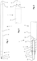
- a peg according to the invention denoted as a whole by 1
- a driving cap according to the invention denoted as a whole by 2.
- the peg 1 according to the invention is shown in its entirety, while in FIGS Figures 2, 3 , 5 and 6 only parts of a peg according to the invention are shown for a better representation.
- a ground peg 1 according to the invention comprises an elongated rod element 3 with a first distal end 4 and a second proximal end 5.
- first distal end 4 forms the tip of the ground peg 1
- second proximal end 5 forms the "head" of the peg 1 and protrudes from the ground for connection to an anchor plate of an industrial tent.
- the distal end 4 is in figure 2 shown in more detail, the proximal end 5 is described in more detail below in connection with FIGS Figures 3 , 5 , 6 , 7 , 8th and 9 described.
- the rod element 3 of a peg 1 according to the invention consists of a fiber composite material.
- the applicant has surprisingly found that the design according to the invention results in a durable solution for anchoring an industrial tent. According to the findings of the applicant, in addition to the loss of component stability due to corrosion, conventional steel pegs are prevented from being able to be used over the long term by such a peg.
- the applicant has identified reduced strength within an iron oxide layer that forms and water absorption within the porous corrosion layer as possible causes.
- ground peg 1 Such problems do not occur with a ground peg 1 according to the invention; first test results and calculations using recognized calculation models confirm the advantages of a ground peg according to the invention and its suitability for long-term use.
- a process for approving a ground peg according to the invention as a construction product for the permanent anchoring of industrial tents was initiated. Once such approval is obtained, the invention opens up the possibility of significantly expanding the commercial viability of industrial tents, namely building approval for use at one site for many years.
- glass fibers are preferred for the fiber content in the fiber composite material.
- Glass fibers as reinforcement fibers are readily available industrially and are cheaper than other suitable reinforcement fibers such as aramid fibers or carbon fibers.
- Safe processes are also available for the industrial production of a rod element 3 with glass fibers as reinforcing fibers, in order to ensure consistent and reliable quality in the case of pegs 1 according to the invention.
- the rod element 3 can be produced in a closed pultrusion process (extrusion process). This process ensures the linear alignment of the fibers along the length of the rod element, complete impregnation of the glass fibers with the resin and an extremely high degree of curing of the resin.
- the fibers give the material its strength and rigidity in the longitudinal direction.
- the task of the resin matrix is to fix the fibers in their position, to transfer the load and to protect the fibers from harmful influences.
- the fiber composite material for the rod element 3 preferably comprises a matrix made of a reaction resin, in particular a phenacrylate resin.
- a reaction resin in particular a phenacrylate resin.
- the design according to the invention results in a more impact-resistant and flexible material due to the less close-meshed crosslinking and is therefore less sensitive to hairline cracks, especially when driven into the ground.
- the industrial tents mentioned at the outset are usually erected on an artificially produced, non-cohesive subsoil that is compacted in layers, in particular for intended longer use.
- a peg 1 according to the invention it has been shown that pre-drilling the hole for the peg 1 with about half to two thirds of the diameter of the peg 1 and then driving in the peg 1 with an electrically, pneumatically or with an internal combustion engine driven hammer, as it is part of the standard equipment of construction companies in civil engineering and road construction. This procedure results in optimal conditions with regard to the work and time required on the one hand and an optimal anchoring of the peg 1 in the ground on the other hand.
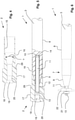
- the rod element 3 is tapered in an approximately conical or chisel-shaped manner towards its distal end 4, as in figure 2 shown.
- the tapered section 6 of the distal end 4 of the peg 1 has a cone angle ⁇ of approximately 20° to 30°, with angles in the range of 15° to 45° also being considered suitable.
- chisel-shaped tapered also means a flattened truncated cone or a wedge-shaped tapering in only one plane. In the latter case, the wedge angle corresponds to the cone angle ⁇ .
- a peg according to the invention can have a protective cap (not shown) made of a material that differs from the fiber composite material of the rod element 3, preferably a metal.
- the protective cap forms a tip to make it easier to drive in the peg 1 and at the same time serves to mechanically protect the distal end 4 of the rod element 3, e.g. on stony ground.
- the rod element 3 has an end section 7 .
- the end section 7 has a reduced cross-section compared to a central section 8 of the rod element 3, in the exemplary embodiment shown here a reduced diameter.
- the rod element 3 tapers towards its proximal end 5 in an approximately conical manner.
- the tapered section 9 of the end section 7 has a cone angle ⁇ of about 20° to 30°, with angles in the range of 15° to 45° also being considered suitable.
- the diameter of the rod element 3 at its proximal end 5 is approximately half the diameter in the middle section 8 of the rod element 3.
- the rod element 3 has a blind hole 10 at the proximal end 5 of the tapered section 9 of the end section 7 .
- An anchor rod 11, 30 is embedded in the blind hole 10.
- the anchor rod 11, 30 is preferably made of a corrosion-resistant steel, for example acid-resistant grade A4 stainless steel, and includes a threaded rod section 12.
- the anchor rod 11, 30 has a square head 13 at its proximal end 5, as in FIGS Figures 3 , 5 and 6 you can see.
- the composite dowel with a continuous threaded rod section 12 of the anchor rod 11 for anchoring in concrete with the W-VD-A anchor rod from Adolf Würth GmbH & Co. KG, Künzelsau, DE has proven to be particularly suitable, as described in the European Technical Assessment ETA- 06/0074 and described in the Figures 3 , 5 , 9 and 10 shown, as well as the force-controlled expanding bonded anchor with anchor rod VMZ-A from MKT Metall-Kunststoff-Technik GmbH & Co. KG, Weilerbach, DE, as in the European Technical Assessment ETA-04/0092 and in the figures 7 and 8th shown.
- the threaded section 12 of the anchor rod 30 only extends over part of the length of the anchor rod 30.
- the embedded part of the anchor rod 30 comprises an expansion cone section 23 in which one or more expansion cones 24 are formed. A positive fit with the embedding compound 14 is achieved via the expansion cone(s) 24 of the expansion cone section 23 .
- the anchor rod 11, 30 is glued in the blind hole 10 by means of an embedding compound 14.
- the embedding compound 14 comprises a vinyl ester resin.
- the vinyl ester resin 14 has a high degree of correspondence with the resin matrix of the fiber composite material of the rod element 3 in terms of chemical and physical properties, so that with professional processing the embedding compound 14 is materially connected to the resin matrix of the fiber composite material and the anchor rod 11, 30 is thereby embedded in the blind hole 10 .
- the depth of the embedding is expediently 5 to 10 times, preferably 6 to 8 times the nominal diameter of the anchor rod 11, 30.
- a particularly expedient anchor rod 11, 30 has a thread size M12, the depth of the embedding should therefore be in the range of 60 mm to 120 mm.
- a peg 1 according to the invention is longitudinally profiled over all or part of the length of the rod element 3 or has radial or spiral circumferential ribs to improve the pull-out resistance.
- the driving cap 2 includes a connecting portion 16 and a head portion 17, wherein the Connecting section 16 comprises a hollow profile 15 which is adapted to the contour of the end section 7 of the rod element 3 in order to introduce forces in the longitudinal direction of the rod element 3.
- the head section 17 is designed as an impact surface 18 at the front.
- the head section 17 of the driving cap 2 protrudes radially in relation to the connecting section 16 and forms a flange 29 at its end axially opposite the impact surface 18 to limit the depth of impact.
- the driving cap 2 In the head section 17 of the driving cap 2 there is a through hole 19 with a nut thread 20 for receiving a jacking screw, in order to be able to gently press the driving cap 2 off the peg 3 if necessary.
- the nut thread 20 has a larger diameter than the threaded rod section 12 of the anchor rod 11, 30.
- the driving cap 2 according to the invention is made of a material that has a higher impact strength than the fiber composite material of the rod element 3, preferably tool steel.
- the connecting section 16 of the driving cap 2 and the conically tapered section 9 of the end section 7 of the rod element 3 have approximately matching cone angles ⁇ of approximately 15° to 45°, preferably approximately 20° to 30°.
- the outside diameter of a driving cap 2 according to the invention in the area of its connecting section 16 should not exceed the outside diameter of the middle section 8 of the rod element 3 in order not to widen the hole for receiving the peg 1 in the ground unnecessarily during driving.
- the length of the connecting section 16 of the drive-in cap 2 is dimensioned such that the drive-in cap 2 touches the end section 7 of the rod element 3 when it is in place, as shown in FIG figures 5 and 7 shown is not completely covered. This ensures that the force is transmitted from the driving cap 2 into the rod element 3 of the peg 1 via the conically tapered section 9 of the end section 7 of the rod element 3 .
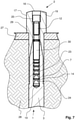
- FIG 6 shows a ground peg 1 according to the invention with a fastening nut 21 screwed onto the anchor rod 11 and an adapter disk 22 for transmitting the tensile forces from an anchor plate 27 of an industrial tent via a ground peg 1 driven into the ground 28 into the ground 28.
- the anchor rod 11 can be held against the square head 13 in order to avoid applying a torsional load in the peg 1.
- figure 7 shows the situation at the end of the driving-in process described above using a driving cap 2 according to the invention with a peg 1 driven completely into the ground 28 .
- the driving cap 2 and thus the peg 1 cannot be driven any further into the ground 28 .
- This arrangement ensures that, on the one hand, a maximum holding force of the peg 1 in the ground 28 is achieved and, on the other hand, sufficient thread length of the threaded rod section 12 of the anchor rod 11, 30 remains via the anchor plate 27 in order to be able to securely fasten a fastening nut 21 and thus a safe To ensure power transmission from the anchor plate 27 in the peg 1.
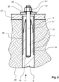
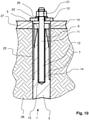
- FIGS 8 and 9 finally show the finished installation situation of a peg according to the invention.
- FIG 8 the situation with an anchor rod 30 of a force-controlled expanding bonded anchor is shown.
- the one in the figure 9 The installation situation illustrated shows an anchor rod 11 with a continuous threaded rod section 12.
- Both figures show that the peg 1 includes a sheathing tube 25 which surrounds the rod element 3 in the region of the end section 7.
- the cladding tube 25 serves to avoid radial expansion of the end section 7 of the rod element 3 when tensile forces are applied to the composite dowel by radial force absorption.
- the sheathing tube 25 preferably protrudes axially beyond the proximal end 5 of the rod element 3 into the anchor plate 27 and thus improves the transmission of shearing forces in the area of the boundary surface between the anchor plate 27 and the base 28 without exposing the rod element 3 to appreciable shearing loads.
- the cladding tube 25 assumes the position during the Driving the peg 1 into the ground 28 was occupied by the connecting section 16 of the driving cap 2 .
- the non-positive connection between anchor plate 27 and peg 1 is produced via an adapter disk 22 and a fastening nut 21 screwed onto the threaded rod section 12 of the anchor posts 11, 30.
- the adapter disk can be contoured, as in figure 6 is seen, or flat, as in the figures 8 and 9 shown.
- a centering of the anchor plate 27 to the peg 1 via the cladding tube 25 is ensured.
- the fastening nut 21 can be attached directly (see figure 6 ) or with a conventional washer 26 (see figures 8 and 9 ) are screwed on.
- the intermediate space is expediently filled with the embedding compound 14 approximately up to the height of the proximal end 5 of the rod element 3 .
- the composite injection mortar VMH from MKT Metall-Kunststoff-Technik GmbH & Co. KG, Weilerbach, DE has proven particularly suitable as the embedding compound 14, as described in the European Technical Assessment ETA-17/0716.
Landscapes
- Engineering & Computer Science (AREA)
- Structural Engineering (AREA)
- Life Sciences & Earth Sciences (AREA)
- General Life Sciences & Earth Sciences (AREA)
- Mining & Mineral Resources (AREA)
- Paleontology (AREA)
- Civil Engineering (AREA)
- General Engineering & Computer Science (AREA)
- Piles And Underground Anchors (AREA)
Applications Claiming Priority (2)
| Application Number | Priority Date | Filing Date | Title |
|---|---|---|---|
| DE202020003192 | 2020-07-24 | ||
| DE202021000006.2U DE202021000006U1 (de) | 2021-01-03 | 2021-01-03 | Erdnagel für ein lndustriezelt |
Publications (2)
| Publication Number | Publication Date |
|---|---|
| EP3943665A2 true EP3943665A2 (fr) | 2022-01-26 |
| EP3943665A3 EP3943665A3 (fr) | 2022-04-20 |
Family
ID=77167952
Family Applications (1)
| Application Number | Title | Priority Date | Filing Date |
|---|---|---|---|
| EP21020386.5A Pending EP3943665A3 (fr) | 2020-07-24 | 2021-07-26 | Piquet de fixation |
Country Status (2)
| Country | Link |
|---|---|
| EP (1) | EP3943665A3 (fr) |
| DE (1) | DE102021003798A1 (fr) |
Citations (20)
| Publication number | Priority date | Publication date | Assignee | Title |
|---|---|---|---|---|
| US1940430A (en) | 1932-06-07 | 1933-12-19 | Morterra Augusto | Peg for holding tents or hangars or for anchoring aircraft and the like |
| DE897321C (de) | 1951-11-30 | 1953-11-19 | Dyckerhoff & Widmann Ag | Endverankerung von vorgespannten Bewehrungsstaeben fuer Stahlbetonkonstruktionen |
| DE1893892U (de) | 1962-12-05 | 1964-05-27 | Albert Gachoud | In den erdboden einschraubbarer erdanker. |
| DE1260752B (de) | 1955-11-12 | 1968-02-08 | Dyckerhoff & Widmann Ag | Verankerung stabfoermiger Spannglieder und Verbindung zweier Spannglieder bei Spannbeton |
| DE3425941A1 (de) | 1984-07-13 | 1986-01-23 | Stump Bohr Gmbh, 8045 Ismaning | Erdanker und erdpfahl |
| EP0585537A1 (fr) | 1992-08-20 | 1994-03-09 | Dyckerhoff & Widmann Ag | Elément de support protégé contre la corrosion pour une ancre de sol ou de roche, pieu comprimé ou similaire |
| DE19702901A1 (de) | 1997-01-28 | 1998-08-06 | Hermann Luettig | Erdnagel |
| EP1045081A1 (fr) | 1999-04-15 | 2000-10-18 | SCHÖCK BAUTEILE GmbH | Barre d'armature |
| DE10121021A1 (de) | 2001-04-28 | 2002-10-31 | Schoeck Entwicklungsgmbh | Bewehrungsstab aus faserverstärktem Kunststoff |
| EP1347114A2 (fr) | 2002-03-23 | 2003-09-24 | Schöck Enwicklungsgesellschaft mbH | Barre d'armature pour constructions en béton et procédé pour la production de telles barres |
| DE10310896A1 (de) | 2003-03-11 | 2004-09-23 | Schöck Entwicklungsgesellschaft mbH | Bewehrungselement für den Betonbau |
| US6871455B1 (en) | 2002-10-10 | 2005-03-29 | Norman Frank Cockman | Drive/auger anchor and stabilizer |
| DE202005009057U1 (de) | 2005-06-09 | 2005-08-25 | Bundesrepublik Deutschland, vertreten durch das Bundeministerium der Verteidigung, dieses vertreten durch das Bundesamt für Wehrtechnik und Beschaffung | Erdnagel |
| AT8142U2 (de) | 2005-08-03 | 2006-02-15 | Oberhofer Stahlbau Ges M B H | Alpinanker |
| DE20122826U1 (de) | 2001-04-28 | 2008-04-03 | Schöck Bauteile GmbH | Bewehrungsstab aus faserverstärktem Kunststoff |
| DE202008003381U1 (de) | 2008-03-10 | 2008-05-15 | Dywidag-Systems International Gmbh | Ankermutter für ein Zugglied sowie Anker |
| DE102007027015A1 (de) | 2007-06-08 | 2008-12-11 | Schöck Bauteile GmbH | Bewehrungsstab |
| WO2010000403A2 (fr) | 2008-07-01 | 2010-01-07 | Alpintechnik Ag | Stabilisateur à dispositif d'ajustage pour des ancrages au sol |
| DE202014007735U1 (de) | 2013-10-01 | 2014-10-16 | Herchenbach Industrie-Zeltebau Gmbh | Verbessertes Industriezelt |
| DE202016004338U1 (de) | 2016-07-15 | 2017-10-18 | Herchenbach Industrie-Zeltebau Gmbh | Verbessertes Industriezelt und Planenverbund |
Family Cites Families (6)
| Publication number | Priority date | Publication date | Assignee | Title |
|---|---|---|---|---|
| DE1759561C3 (de) | 1968-05-15 | 1978-06-15 | Dyckerhoff & Widmann Ag, 8000 Muenchen | Verfahren zum Herstellen von Verpreßankem und Vorrichtung zum Durchführen des Verfahrens |
| DE2606095B1 (de) * | 1976-02-16 | 1976-12-02 | Dyckerhoff & Widmann Ag | Ausbaubarer verpressanker mit zerstoerbarem ankerkoerper |
| JP4503940B2 (ja) * | 2003-05-29 | 2010-07-14 | 東京製綱株式会社 | グラウンドアンカー |
| US8851801B2 (en) * | 2003-12-18 | 2014-10-07 | R&B Leasing, Llc | Self-centralizing soil nail and method of creating subsurface support |
| DE102007048623A1 (de) * | 2006-10-10 | 2008-04-17 | Josef Haas | Erdanker aus witterungsbeständigem Material |
| JP5324927B2 (ja) * | 2009-01-07 | 2013-10-23 | 前田工繊株式会社 | 繊維アンカー及びそれを使用したアンカーの施工法 |
-
2021
- 2021-07-26 EP EP21020386.5A patent/EP3943665A3/fr active Pending
- 2021-07-26 DE DE102021003798.7A patent/DE102021003798A1/de active Pending
Patent Citations (24)
| Publication number | Priority date | Publication date | Assignee | Title |
|---|---|---|---|---|
| US1940430A (en) | 1932-06-07 | 1933-12-19 | Morterra Augusto | Peg for holding tents or hangars or for anchoring aircraft and the like |
| DE897321C (de) | 1951-11-30 | 1953-11-19 | Dyckerhoff & Widmann Ag | Endverankerung von vorgespannten Bewehrungsstaeben fuer Stahlbetonkonstruktionen |
| DE1260752B (de) | 1955-11-12 | 1968-02-08 | Dyckerhoff & Widmann Ag | Verankerung stabfoermiger Spannglieder und Verbindung zweier Spannglieder bei Spannbeton |
| DE1893892U (de) | 1962-12-05 | 1964-05-27 | Albert Gachoud | In den erdboden einschraubbarer erdanker. |
| DE3425941A1 (de) | 1984-07-13 | 1986-01-23 | Stump Bohr Gmbh, 8045 Ismaning | Erdanker und erdpfahl |
| EP0585537A1 (fr) | 1992-08-20 | 1994-03-09 | Dyckerhoff & Widmann Ag | Elément de support protégé contre la corrosion pour une ancre de sol ou de roche, pieu comprimé ou similaire |
| DE19702901A1 (de) | 1997-01-28 | 1998-08-06 | Hermann Luettig | Erdnagel |
| EP1045081A1 (fr) | 1999-04-15 | 2000-10-18 | SCHÖCK BAUTEILE GmbH | Barre d'armature |
| DE19917126A1 (de) | 1999-04-15 | 2000-10-19 | Schoeck Bauteile Gmbh | Bewehrungsstab |
| DE10121021A1 (de) | 2001-04-28 | 2002-10-31 | Schoeck Entwicklungsgmbh | Bewehrungsstab aus faserverstärktem Kunststoff |
| DE20122826U1 (de) | 2001-04-28 | 2008-04-03 | Schöck Bauteile GmbH | Bewehrungsstab aus faserverstärktem Kunststoff |
| EP1347114A2 (fr) | 2002-03-23 | 2003-09-24 | Schöck Enwicklungsgesellschaft mbH | Barre d'armature pour constructions en béton et procédé pour la production de telles barres |
| DE10213153A1 (de) | 2002-03-23 | 2003-10-02 | Schoeck Entwicklungsgmbh | Bewehrungsstab für den Betonbau und Verfahren zur Herstellung von Bewehrungsstäben |
| US6871455B1 (en) | 2002-10-10 | 2005-03-29 | Norman Frank Cockman | Drive/auger anchor and stabilizer |
| DE10310896A1 (de) | 2003-03-11 | 2004-09-23 | Schöck Entwicklungsgesellschaft mbH | Bewehrungselement für den Betonbau |
| DE202005009057U1 (de) | 2005-06-09 | 2005-08-25 | Bundesrepublik Deutschland, vertreten durch das Bundeministerium der Verteidigung, dieses vertreten durch das Bundesamt für Wehrtechnik und Beschaffung | Erdnagel |
| AT8142U2 (de) | 2005-08-03 | 2006-02-15 | Oberhofer Stahlbau Ges M B H | Alpinanker |
| DE102007027015A1 (de) | 2007-06-08 | 2008-12-11 | Schöck Bauteile GmbH | Bewehrungsstab |
| DE202008003381U1 (de) | 2008-03-10 | 2008-05-15 | Dywidag-Systems International Gmbh | Ankermutter für ein Zugglied sowie Anker |
| WO2010000403A2 (fr) | 2008-07-01 | 2010-01-07 | Alpintechnik Ag | Stabilisateur à dispositif d'ajustage pour des ancrages au sol |
| DE202014007735U1 (de) | 2013-10-01 | 2014-10-16 | Herchenbach Industrie-Zeltebau Gmbh | Verbessertes Industriezelt |
| EP2907941A1 (fr) | 2013-10-01 | 2015-08-19 | Herchenbach Industrie-Zeltebau GmbH | Tente industrielle améliorée |
| DE202016004338U1 (de) | 2016-07-15 | 2017-10-18 | Herchenbach Industrie-Zeltebau Gmbh | Verbessertes Industriezelt und Planenverbund |
| EP3269901A1 (fr) | 2016-07-15 | 2018-01-17 | Herchenbach Industrie-Zeltebau GmbH | Tente industrielle améliorée et ensemble de canevas de toile de tente |
Also Published As
| Publication number | Publication date |
|---|---|
| DE102021003798A1 (de) | 2022-01-27 |
| EP3943665A3 (fr) | 2022-04-20 |
Similar Documents
| Publication | Publication Date | Title |
|---|---|---|
| EP0394179B1 (fr) | Boulon d'ancrage rigide profilé et extensible avec élément d'expansion | |
| EP2257690B1 (fr) | Cheville autoforeuse protégée contre la corrosion, et bloc d'éléments de cheville, et leur procédé de fabrication | |
| EP3559484B1 (fr) | Système d'assemblage ou de blindage de composants | |
| DE19947913C2 (de) | Befestigungselement zur Anbringung von Lasten an eine eine Wärmedämmung aufweisende Gebäudewand | |
| DE102006000486A1 (de) | Ankerstab und Anordnung zum Verstärken von bestehenden Bauteilen gegen Durchstanzen mit einem solchen Ankerstab | |
| DE202010007750U1 (de) | Ertüchtigtes Fundament | |
| DE102005045574A1 (de) | Drehfundament zur Verankerung im Erdboden | |
| DE102011102825B4 (de) | Verbindungsanordnung und Verfahren zur Herstellung einer Durchstanzsicherung | |
| EP0976873A1 (fr) | Ancrage d'injection ou précontrainte | |
| DE19513202A1 (de) | Vorrichtung zur Verankerung von Bewehrungs- bzw. Spannstählen in Verankerungsgründen | |
| EP2893139B1 (fr) | Ensemble d'ancrage haute résistance d'un élément de précontrainte dans une pièce, l'élément de précontrainte comportant une tige de précontrainte, et procédé de production dudit ancrage | |
| EP2225428B1 (fr) | Élément d'ancrage | |
| EP3943665A2 (fr) | Piquet de fixation | |
| DE202021000006U1 (de) | Erdnagel für ein lndustriezelt | |
| EP2138728A2 (fr) | Tige d'ancre destinée à l'ancrage dans un trou de forage | |
| DE102010009140B4 (de) | System zur Bodenverankerung von Aufbauten | |
| EP2808449B1 (fr) | Pieu foré pour fondation | |
| DE2201950B2 (de) | Verpreßanker zum Verankern von Bauteilen in erdigem oder felsigem Baugrund | |
| EP2400063A1 (fr) | Système de flottation | |
| CH683110A5 (de) | Befestigungsanker. | |
| DE2019166A1 (de) | Injektionszuganker | |
| DE7905976U1 (de) | Vorrichtung zum befestigen eines geruests an einer gebaeudewand | |
| EP3974599A1 (fr) | Procédé de traitement des plafonds en bois dans les bâtiments, en particulier des plafonds en bois classés dans les bâtiments | |
| DE3508107C2 (fr) | ||
| DE19743415A1 (de) | Selbstbohrender Betonpfahl |
Legal Events
| Date | Code | Title | Description |
|---|---|---|---|
| PUAI | Public reference made under article 153(3) epc to a published international application that has entered the european phase |
Free format text: ORIGINAL CODE: 0009012 |
|
| STAA | Information on the status of an ep patent application or granted ep patent |
Free format text: STATUS: THE APPLICATION HAS BEEN PUBLISHED |
|
| AK | Designated contracting states |
Kind code of ref document: A2 Designated state(s): AL AT BE BG CH CY CZ DE DK EE ES FI FR GB GR HR HU IE IS IT LI LT LU LV MC MK MT NL NO PL PT RO RS SE SI SK SM TR |
|
| PUAL | Search report despatched |
Free format text: ORIGINAL CODE: 0009013 |
|
| AK | Designated contracting states |
Kind code of ref document: A3 Designated state(s): AL AT BE BG CH CY CZ DE DK EE ES FI FR GB GR HR HU IE IS IT LI LT LU LV MC MK MT NL NO PL PT RO RS SE SI SK SM TR |
|
| RIC1 | Information provided on ipc code assigned before grant |
Ipc: E02D 5/80 20060101AFI20220316BHEP |
|
| STAA | Information on the status of an ep patent application or granted ep patent |
Free format text: STATUS: REQUEST FOR EXAMINATION WAS MADE |
|
| 17P | Request for examination filed |
Effective date: 20221019 |
|
| RBV | Designated contracting states (corrected) |
Designated state(s): AL AT BE BG CH CY CZ DE DK EE ES FI FR GB GR HR HU IE IS IT LI LT LU LV MC MK MT NL NO PL PT RO RS SE SI SK SM TR |