EP3938322B1 - Abwasserreinigungsvorrichtung und verfahren zum reinigen von abwasser - Google Patents
Abwasserreinigungsvorrichtung und verfahren zum reinigen von abwasser Download PDFInfo
- Publication number
- EP3938322B1 EP3938322B1 EP20712891.9A EP20712891A EP3938322B1 EP 3938322 B1 EP3938322 B1 EP 3938322B1 EP 20712891 A EP20712891 A EP 20712891A EP 3938322 B1 EP3938322 B1 EP 3938322B1
- Authority
- EP
- European Patent Office
- Prior art keywords
- agitator
- vertical
- hyperboloid
- wastewater
- suspension
- Prior art date
- Legal status (The legal status is an assumption and is not a legal conclusion. Google has not performed a legal analysis and makes no representation as to the accuracy of the status listed.)
- Active
Links
Images



Classifications
-
- C—CHEMISTRY; METALLURGY
- C02—TREATMENT OF WATER, WASTE WATER, SEWAGE, OR SLUDGE
- C02F—TREATMENT OF WATER, WASTE WATER, SEWAGE, OR SLUDGE
- C02F3/00—Biological treatment of water, waste water, or sewage
- C02F3/02—Aerobic processes
- C02F3/12—Activated sludge processes
- C02F3/1278—Provisions for mixing or aeration of the mixed liquor
- C02F3/1284—Mixing devices
-
- C—CHEMISTRY; METALLURGY
- C02—TREATMENT OF WATER, WASTE WATER, SEWAGE, OR SLUDGE
- C02F—TREATMENT OF WATER, WASTE WATER, SEWAGE, OR SLUDGE
- C02F3/00—Biological treatment of water, waste water, or sewage
- C02F3/02—Aerobic processes
- C02F3/12—Activated sludge processes
- C02F3/1236—Particular type of activated sludge installations
- C02F3/1263—Sequencing batch reactors [SBR]
-
- B—PERFORMING OPERATIONS; TRANSPORTING
- B01—PHYSICAL OR CHEMICAL PROCESSES OR APPARATUS IN GENERAL
- B01F—MIXING, e.g. DISSOLVING, EMULSIFYING OR DISPERSING
- B01F23/00—Mixing according to the phases to be mixed, e.g. dispersing or emulsifying
- B01F23/20—Mixing gases with liquids
- B01F23/23—Mixing gases with liquids by introducing gases into liquid media, e.g. for producing aerated liquids
- B01F23/233—Mixing gases with liquids by introducing gases into liquid media, e.g. for producing aerated liquids using driven stirrers with completely immersed stirring elements
- B01F23/2331—Mixing gases with liquids by introducing gases into liquid media, e.g. for producing aerated liquids using driven stirrers with completely immersed stirring elements characterised by the introduction of the gas along the axis of the stirrer or along the stirrer elements
- B01F23/23311—Mixing gases with liquids by introducing gases into liquid media, e.g. for producing aerated liquids using driven stirrers with completely immersed stirring elements characterised by the introduction of the gas along the axis of the stirrer or along the stirrer elements through a hollow stirrer axis
-
- B—PERFORMING OPERATIONS; TRANSPORTING
- B01—PHYSICAL OR CHEMICAL PROCESSES OR APPARATUS IN GENERAL
- B01F—MIXING, e.g. DISSOLVING, EMULSIFYING OR DISPERSING
- B01F23/00—Mixing according to the phases to be mixed, e.g. dispersing or emulsifying
- B01F23/20—Mixing gases with liquids
- B01F23/23—Mixing gases with liquids by introducing gases into liquid media, e.g. for producing aerated liquids
- B01F23/233—Mixing gases with liquids by introducing gases into liquid media, e.g. for producing aerated liquids using driven stirrers with completely immersed stirring elements
- B01F23/2331—Mixing gases with liquids by introducing gases into liquid media, e.g. for producing aerated liquids using driven stirrers with completely immersed stirring elements characterised by the introduction of the gas along the axis of the stirrer or along the stirrer elements
- B01F23/23314—Mixing gases with liquids by introducing gases into liquid media, e.g. for producing aerated liquids using driven stirrers with completely immersed stirring elements characterised by the introduction of the gas along the axis of the stirrer or along the stirrer elements through a hollow stirrer element
-
- B—PERFORMING OPERATIONS; TRANSPORTING
- B01—PHYSICAL OR CHEMICAL PROCESSES OR APPARATUS IN GENERAL
- B01F—MIXING, e.g. DISSOLVING, EMULSIFYING OR DISPERSING
- B01F27/00—Mixers with rotary stirring devices in fixed receptacles; Kneaders
- B01F27/05—Stirrers
- B01F27/07—Stirrers characterised by their mounting on the shaft
- B01F27/072—Stirrers characterised by their mounting on the shaft characterised by the disposition of the stirrers with respect to the rotating axis
- B01F27/0725—Stirrers characterised by their mounting on the shaft characterised by the disposition of the stirrers with respect to the rotating axis on the free end of the rotating axis
-
- B—PERFORMING OPERATIONS; TRANSPORTING
- B01—PHYSICAL OR CHEMICAL PROCESSES OR APPARATUS IN GENERAL
- B01F—MIXING, e.g. DISSOLVING, EMULSIFYING OR DISPERSING
- B01F27/00—Mixers with rotary stirring devices in fixed receptacles; Kneaders
- B01F27/05—Stirrers
- B01F27/11—Stirrers characterised by the configuration of the stirrers
- B01F27/117—Stirrers provided with conical-shaped elements, e.g. funnel-shaped
-
- B—PERFORMING OPERATIONS; TRANSPORTING
- B01—PHYSICAL OR CHEMICAL PROCESSES OR APPARATUS IN GENERAL
- B01F—MIXING, e.g. DISSOLVING, EMULSIFYING OR DISPERSING
- B01F27/00—Mixers with rotary stirring devices in fixed receptacles; Kneaders
- B01F27/80—Mixers with rotary stirring devices in fixed receptacles; Kneaders with stirrers rotating about a substantially vertical axis
- B01F27/81—Mixers with rotary stirring devices in fixed receptacles; Kneaders with stirrers rotating about a substantially vertical axis the stirrers having central axial inflow and substantially radial outflow
-
- B—PERFORMING OPERATIONS; TRANSPORTING
- B01—PHYSICAL OR CHEMICAL PROCESSES OR APPARATUS IN GENERAL
- B01F—MIXING, e.g. DISSOLVING, EMULSIFYING OR DISPERSING
- B01F27/00—Mixers with rotary stirring devices in fixed receptacles; Kneaders
- B01F27/80—Mixers with rotary stirring devices in fixed receptacles; Kneaders with stirrers rotating about a substantially vertical axis
- B01F27/85—Mixers with rotary stirring devices in fixed receptacles; Kneaders with stirrers rotating about a substantially vertical axis with two or more stirrers on separate shafts
-
- B—PERFORMING OPERATIONS; TRANSPORTING
- B01—PHYSICAL OR CHEMICAL PROCESSES OR APPARATUS IN GENERAL
- B01F—MIXING, e.g. DISSOLVING, EMULSIFYING OR DISPERSING
- B01F27/00—Mixers with rotary stirring devices in fixed receptacles; Kneaders
- B01F27/80—Mixers with rotary stirring devices in fixed receptacles; Kneaders with stirrers rotating about a substantially vertical axis
- B01F27/85—Mixers with rotary stirring devices in fixed receptacles; Kneaders with stirrers rotating about a substantially vertical axis with two or more stirrers on separate shafts
- B01F27/851—Mixers with rotary stirring devices in fixed receptacles; Kneaders with stirrers rotating about a substantially vertical axis with two or more stirrers on separate shafts the receptacle being subdivided in adjacent compartments
-
- C—CHEMISTRY; METALLURGY
- C02—TREATMENT OF WATER, WASTE WATER, SEWAGE, OR SLUDGE
- C02F—TREATMENT OF WATER, WASTE WATER, SEWAGE, OR SLUDGE
- C02F3/00—Biological treatment of water, waste water, or sewage
- C02F3/02—Aerobic processes
- C02F3/12—Activated sludge processes
- C02F3/20—Activated sludge processes using diffusers
- C02F3/205—Moving, e.g. rotary, diffusers; Stationary diffusers with moving, e.g. rotary, distributors
-
- B—PERFORMING OPERATIONS; TRANSPORTING
- B01—PHYSICAL OR CHEMICAL PROCESSES OR APPARATUS IN GENERAL
- B01F—MIXING, e.g. DISSOLVING, EMULSIFYING OR DISPERSING
- B01F2101/00—Mixing characterised by the nature of the mixed materials or by the application field
- B01F2101/305—Treatment of water, waste water or sewage
-
- C—CHEMISTRY; METALLURGY
- C02—TREATMENT OF WATER, WASTE WATER, SEWAGE, OR SLUDGE
- C02F—TREATMENT OF WATER, WASTE WATER, SEWAGE, OR SLUDGE
- C02F2301/00—General aspects of water treatment
- C02F2301/08—Multistage treatments, e.g. repetition of the same process step under different conditions
-
- Y—GENERAL TAGGING OF NEW TECHNOLOGICAL DEVELOPMENTS; GENERAL TAGGING OF CROSS-SECTIONAL TECHNOLOGIES SPANNING OVER SEVERAL SECTIONS OF THE IPC; TECHNICAL SUBJECTS COVERED BY FORMER USPC CROSS-REFERENCE ART COLLECTIONS [XRACs] AND DIGESTS
- Y02—TECHNOLOGIES OR APPLICATIONS FOR MITIGATION OR ADAPTATION AGAINST CLIMATE CHANGE
- Y02W—CLIMATE CHANGE MITIGATION TECHNOLOGIES RELATED TO WASTEWATER TREATMENT OR WASTE MANAGEMENT
- Y02W10/00—Technologies for wastewater treatment
- Y02W10/10—Biological treatment of water, waste water, or sewage
Definitions
- the invention relates to a waste water cleaning device and a method for cleaning waste water, in particular a so-called SBR method.
- the EP 1 132 348 B1 discloses a waste water purification device and a waste water purification method for biological waste water treatment.
- the waste water treatment device has an elongated basin, which is divided into several treatment sections by means of partitions.
- SBR process Sequencing Batch Reactor
- the wastewater is brought into contact with activated sludge in a first treatment section.
- the suspension formed from the waste water and the activated sludge is then aerated, in particular in a second treatment section.
- the suspension is neither aerated nor moved.
- the clarified water is drawn off as the supernatant using a decanter.
- the SBR process is usually carried out in batches.
- the movable partitions are made of a waterproof, flexible film. Such a film is not particularly durable. Pumps and pipes are required to transfer the waste water from one treatment section to the next. The clarification efficiency of the known waste water cleaning device is not too high.
- JP2006255514A discloses another prior art water treatment system.
- the object of the invention is to eliminate the disadvantages of the prior art.
- a waste water cleaning device and a method are to be specified which enable waste water to be cleaned with improved efficiency.
- the waste water purification device and the method should in particular also enable continuous purification of waste water.
- the waste water flows from the inlet on the first narrow side to the decanter on the second narrow side.
- the first vertical agitator is arranged downstream of the inlet and the second vertical agitator is arranged downstream of the first vertical agitator.
- Each of the vertical agitators has a hyperboloid agitator as the agitator.
- a flow is formed which is directed along the stirring shaft in the direction of the hyperboloid mixing body.
- the flow turns to a substantially horizontal direction on the surface of the hyperboloid impeller. At some distance from the peripheral edge of the hyperboloid agitator, the flow then turns back into a vertical direction directed towards the surface of the waste water.
- the flow then runs approximately parallel to the surface and then bends back in the direction of the agitator shaft.
- a circulating flow is therefore formed by the effect of the vertical agitator.
- the flow also rotates axially around the agitator shaft according to its direction of rotation. Because the first vertical agitator and the second vertical agitator are operated with a different direction of rotation, a zone is formed between the successive vertical agitators, in which the flow is directed essentially vertically upwards in the direction of the surface of the waste water. There the flow divides and returns to the respective treatment section.
- the use of two counter-rotating vertical agitators proposed according to the invention makes it possible to create treatment sections in an elongated basin, in which waste water can be subjected to different treatment steps, without the provision of partition walls.
- the wastewater in the first treatment section, can be contacted with a high concentration of activated sludge.
- the effluent in the second treatment section, can be contacted with a lower concentration of activated sludge and, preferably at the same time, aerated.
- the ventilation can the treatment sections can be varied.
- the intensity of the aeration and the speed of rotation of the hyperboloid mixing elements can also be varied in the treatment sections.
- the proposed waste water cleaning device enables efficient cleaning of waste water. It also enables a continuous or quasi-continuous process flow. Pumps and lines for transferring the treated wastewater from one treatment section to the next are not required. A transfer of the treated effluent from one treatment section to the next can be controlled by suitably controlling the rotation speed of the vertical agitators, the amount of effluent supplied through the inlet and/or the amount of effluent removed by means of the decanter.
- first transport ribs provided on an upper side of the hyperboloid mixing body have a first curvature and transport ribs provided on a further upper side of the second hyperboloid mixing body have a second curvature opposite to the first curvature.
- the proposed configuration of the transport ribs can improve the agitation efficiency and in particular the formation of the circulating flow.
- the ribs can also be straight.
- the first transport ribs have a first angle with respect to the radial direction and the second transport ribs have an opposite second angle with respect to the radial direction.
- At least one of the hyperboloid stirring bodies is designed as a hollow body and has a central opening for the passage of air as well as ventilation openings.
- the agitator shaft can be designed as a hollow shaft for supplying air to the central opening.
- the drive device can have a transmission with a hollow transmission shaft, one end of which is connected to the fan and the other end of which is connected to the hollow shaft.
- the aeration device has at least one perforated air supply line supported on a floor of the basin, which is connected to the blower.
- - Devices can also be provided which have a large number of perforated air supply lines. Such devices are well known in the prior art.
- a plurality of first vertical agitators following one another in the direction of flow are provided in the first treatment section and/or a plurality of second vertical agitators following one another in the direction of flow in the second treatment section, with the hyperboloid agitator bodies of directly successive vertical agitators each being rotated with an opposite direction of rotation.
- the proposed configuration is particularly suitable for long treatment tanks and for treating large quantities of waste water.
- the treatment tank can also be designed in such a way that several vertical agitators are arranged in a direction perpendicular to the flow direction. If vertical agitators are arranged next to one another in a direction perpendicular to the direction of flow, they are preferably each operated with the same direction of rotation.
- the hyperboloid stirring body is designed as a hollow body. It expediently has a central opening for supplying air and air outlet openings.
- the agitator shaft can be designed as a hollow shaft for supplying air to the central opening.
- a drive device can have a gearbox with a hollow gearbox shaft, one end of which is connected to the fan and the other end of which is connected to the hollow shaft.
- the proposed method allows a particularly efficient cleaning of waste water. Because of the proposed opposite directions of rotation of the successive agitators, it is possible to expose the waste water to different conditions in the treatment sections formed thereby.
- the effluent in the first treatment section, can be contacted with a high concentration of activated sludge, whereas in the second treatment section, the effluent can be contacted with an increased concentration of air.
- the process can be carried out either as a batch process or as a continuous or quasi-continuous process.
- the first rotational speed is selected to be lower than the second rotational speed. This makes it possible to contact the wastewater in the first treatment section with a high concentration of activated sludge. In particular, an undesired transport of activated sludge from the first treatment section into the second treatment section can be reduced or prevented.
- first rotational speeds can also be selected to be different.
- the first rotational speed may increase in the downstream direction.
- the second rotational speeds can decrease towards the third treatment section. This supports the desired separation of the suspension into activated sludge and treated waste water in the third treatment stage.
- the first rotation speed is chosen such that a concentration of activated sludge in a bottom half of the suspension is greater than in a surface-side upper half.
- the wastewater can be brought into contact with a particularly high concentration of activated sludge, particularly in the lower half on the bottom side.
- first vertical agitators can be used in succession in the flow direction and/or in the second treatment section in A plurality of second vertical agitators may be provided in succession in the direction of flow, with the hyperboloid agitators of immediately successive vertical agitators each being rotated in an opposite direction. A specified service life of the waste water in the respective treatment sections can thus be ensured.
- the waste water is fed in continuously.
- the method can be carried out according to the SBR method.
- the waste water is stirred in several consecutive steps. It can be aerated at one or more steps at the same time. However, it is also possible to aerate the waste water without stirring it at the same time.
- the waste water is only agitated with low intensity. This step is not aerated. The step is for sedimentation.
- the waste water is stirred with little intensity, if at all, in the first treatment section.
- decanting takes place in the third treatment section.
- waste water can be fed continuously to the treatment tank through the inlet. Decanting can also be done continuously.
- the suspension is neither stirred nor aerated by means of the aeration device during the step of allowing it to rest in the second treatment section and/or third treatment section. Furthermore, the suspension can neither be stirred nor aerated by means of the aeration device in the step of allowing it to rest in the first treatment section either. This accelerates the step of letting go. The efficiency of the method can thus be further increased.
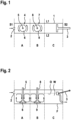
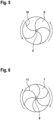
- the Figures 1 and 2 show intentions of a first sewage purification device.
- the first waste water purification device comprises an elongated tank 1, which has an inlet 2 for supplying waste water on its first narrow side S1.
- a decanter 3 for discharging cleaned waste water is provided on a second narrow side S2 opposite the first narrow side S1.
- a first long side of the basin 1 is denoted by L1, and an opposite second long side is denoted by L2.
- a first vertical agitator 4 is provided downstream of the inlet, which has a first hyperboloid agitator body 6 on a first agitator shaft 5 .
- Reference number 7 designates a second vertical agitator which has a second hyperboloid agitator body 9 on a second agitator shaft 8 .
- the first vertical agitator 4 has a first drive device (not shown here), with which the first hyperboloid agitator body 6 can be rotated counterclockwise in a plan view.
- the second vertical agitator 7 is provided with a second drive device (not shown here), with which the second hyperboloid agitator body 9 can be rotated clockwise.
- first vertical agitators 4a, 4b and then two second vertical agitators 7a, 7b are provided in a flow direction directed from the inlet 2 to the decanter 3 in succession.
- the first drive devices (not shown here) of the first vertical agitators 4a, 4b are designed such that whose hyperboloid stirring bodies 6a, 6b are rotated in opposite directions.
- the second drive devices (not shown here) are designed in such a way that the second hyperboloid stirring bodies 9a, 9b are also rotated in the opposite direction.
- the first hyperboloid agitator 6b of the first vertical agitator 5b is advantageously rotated in the opposite direction to the second hyperboloid agitator 9a of the second vertical agitator 7a.
- successive hyperboloid stirring bodies 6a, 6b, 9a, 9b are rotated in opposite directions.
- At least one first vertical agitator 4, 4a, 4b is arranged in a first treatment section A of the basin 1 provided downstream of the inlet 2.
- At least one second vertical agitator 7, 7a, 7b is arranged in a second treatment section B provided downstream of the first treatment section A.
- a third treatment section C following downstream of the second treatment section B no vertical agitator is arranged here.
- the decanter 3 is located there.
- at least one vertical agitator is also provided in the third treatment section C.
- Aeration devices are provided in the first treatment section A and in the second treatment section B. These can be perforated fore-lines laid on the floor F of the basin 1 . According to a preferred embodiment, the air is supplied through the hyperboloid stirring elements 6, 6a, 6b, 9, 9a, 9b, which are preferably designed as hollow bodies.
- the function of the proposed sewage cleaning devices is as follows: The rotation of one of the hyperboloid agitators 6, 6a, 6b, 9, 9a, 9b results in a flow which flows from a surface O of a waste water W contained in the basin 1 along the vertical agitator shaft 5, 8 onto an upper side of the hyperboloid Stirring body 6, 6a, 6b, 9, 9a, 9b is directed. The flow then bends parallel to the top of the hyperboloid mixing body 6, 6a, 6b, 9, 9a, 9b in a substantially horizontal direction. It then bends further and is again directed toward the top O. Overall, a circulating flow directed from the top O to a bottom F of the basin 1 results.
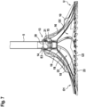
- FIG 5 shows, by way of example, a plan view of an upper side O1 of the first hyperboloid mixing body.
- First transport ribs 10 extend on the first top side O1 and run from the first agitator shaft 5 in the radial direction toward the peripheral edge U of the first hyperboloid agitator body 6 .
- the first transport ribs 10 then bend following a first curvature towards the peripheral edge U in a tangential direction.
- FIG. 6 shows a plan view of a further upper side of the second hyperboloid stirring body 7.
- second transport ribs 11 extend again in the radial direction from the second stirring shaft 8 and bend in a tangential direction towards the peripheral edge U in accordance with a second curvature.
- the first curvature is opposite to the second curvature.
- the first hyperboloid stirring body 5 is particularly suitable for counterclockwise rotation
- the second hyperboloid stirring body 7 is suitable for clockwise rotation.
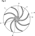
- the Figures 7 to 11 show an advantageous embodiment of the hyperboloid mixing body.
- a hyperboloid stirring body is attached to a hollow stirring shaft 12 .
- the hyperboloid stirring body has a central connection section denoted by the reference number 13 .
- the connection section 13 has a central opening 14 for the passage of air.
- Reference number 16 designates an upper shell, from the first upper side O1 of which transport ribs 17 extend.
- Reference number 18 designates a lower shell, walls 19 extending from the second upper side O2 of said lower shell.
- the reference number 20 designates an insert which is provided downstream of the opening 14 and forms an air distribution space 15 .
- the insert 20 is designed in the manner of a conical cup and has a plurality of air distribution openings 21 on its peripheral wall. Each of the air distribution openings 21 opens into an air duct 22 formed by adjacent walls 19 and the upper shell 16 and the lower shell 18. Shear ribs 23 are attached to the peripheral edge of a second underside U2 of the lower shell 18.
- FIG. 8 shows a plan view of the first top side O1 of the upper shell.
- the transport ribs 17 extending from the first upper side O1 can be seen, which first run in a radial direction from the opening 14 and then bend toward the peripheral edge U in a tangential direction.
- the insert 20 with the air distribution openings 21 downstream of the opening 14 can also be seen.
- FIG. 9 shows a bottom view according to 8 .
- the transport ribs 17 in the form of depressions can be seen on a first underside U1 of the upper shell 16 .
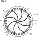
- FIG. 10 shows a plan view of the second upper side O2 of the lower shell 18.
- the lower shell 18 is closed in its center, ie opposite the opening 14 provided in the upper shell 16.
- FIG. The walls 19 extend from the second upper side O2.
- the walls 19 run—similar to the transport ribs 17—first in a radial direction from the center and then bend in an essentially tangential direction toward the peripheral edge U.
- a plurality of holding devices 24 are located on the peripheral edge U, which form indentations in the second upper side O2.
- the holding devices 24 are used--as in particular in conjunction with the one explained below 11 can be seen - the inclusion and attachment of the shear ribs 23.
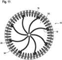
- 11 shows a bottom view according to 10 .
- the walls 19 in the form of indentations can be seen on a second underside U2 of the lower shell.
- the holding devices 24, on the other hand, extend from the second underside U2. In this respect, it is also referred to 7 referred.
- An air outlet opening 25 is provided in each case between two adjacent holding devices 24 or two adjacent shearing ribs 23 .
- FIG. 12 shows a schematic sectional view through a transmission 27, which is drivingly connected to a motor 26.
- the gear 27 has a hollow gear shaft 28 whose first end is connected to an air supply line 29 .
- a fan connected to the air supply line 29 is not shown here.
- a second end E2 of the transmission hollow shaft 28 is connected to the hollow agitator shaft 12 . How out 7 can be seen, a third end E3 of the hollow agitator shaft 12 with the in Figures 7 to 11 connected to the hyperboloid mixing body shown.
- the resulting stirring and gassing device can, for example, be attached to a traverse or bridge 30 (see 12 ) be attached, which spans the pool 1 between the two long sides L1 and L2.
- a method for cleaning waste water in particular an SBR method, can be carried out particularly efficiently.
- a predetermined quantity of activated sludge is added to the wastewater W present in the basin 1 in the first treatment section A.
- the at least one first vertical agitator 4, 4a, 4b is rotated at a predetermined first rotational speed, so that a suspension is formed from the waste water W and the activated sludge.
- the at least one second vertical agitator 7, 7a, 7b is rotated at a second rotational speed.
- the second speed of rotation is advantageously greater than the first speed of rotation.
- a suspension with a high concentration of activated sludge forms in the first treatment section A and in the second treatment section B a suspension with a lower concentration of activated sludge.
- the suspension When operating the vertical agitators, the suspension is in accordance with the 2 and 4 flow direction shown circulated.
- the suspension is aerated with air, advantageously at the same time.
- microorganisms contained in the activated sludge are nourished.
- the microorganisms break down organic impurities in the wastewater.
- the suspension In the third treatment section C, the suspension is at rest. However, the suspension can also be stirred slowly in the third treatment section C by means of at least one third vertical stirrer (not shown here). She points there usually an even lower concentration of activated sludge than in the second treatment section B. In the third treatment section C, a supernatant formed from treated waste water forms, which is drawn off by means of the decanter 3 . - During decanting, the at least one third vertical agitator is advantageously switched off.
- the proposed method can advantageously be carried out continuously, in that waste water is constantly fed in through the inlet 2 and a corresponding amount of clarified waste water is discharged through the decanter 3 .
- the proposed method can also be carried out in a conventional manner in the manner of an SBR method.
- the first 4, 4a, 4b and second vertical agitators 7, 7a, 7b are only operated intermittently.
- a supernatant formed from clarified waste water forms in the treatment section C, which can then be drawn off by means of the decanter 3.
Landscapes
- Chemical & Material Sciences (AREA)
- Life Sciences & Earth Sciences (AREA)
- Chemical Kinetics & Catalysis (AREA)
- Organic Chemistry (AREA)
- Engineering & Computer Science (AREA)
- Environmental & Geological Engineering (AREA)
- Water Supply & Treatment (AREA)
- Hydrology & Water Resources (AREA)
- Microbiology (AREA)
- Biodiversity & Conservation Biology (AREA)
- Mixers Of The Rotary Stirring Type (AREA)
- Activated Sludge Processes (AREA)
- Aeration Devices For Treatment Of Activated Polluted Sludge (AREA)
- Cleaning By Liquid Or Steam (AREA)
- Physical Water Treatments (AREA)
- Electrical Discharge Machining, Electrochemical Machining, And Combined Machining (AREA)
- Cleaning In General (AREA)
- Treatment Of Liquids With Adsorbents In General (AREA)
- Biological Treatment Of Waste Water (AREA)
Applications Claiming Priority (2)
| Application Number | Priority Date | Filing Date | Title |
|---|---|---|---|
| DE102019111489.6A DE102019111489A1 (de) | 2019-05-03 | 2019-05-03 | Abwasserreinigungsvorrichtung und Verfahren zum Reinigen von Abwasser |
| PCT/EP2020/057110 WO2020224838A1 (de) | 2019-05-03 | 2020-03-16 | Abwasserreinigungsvorrichtung und verfahren zum reinigen von abwasser |
Publications (2)
| Publication Number | Publication Date |
|---|---|
| EP3938322A1 EP3938322A1 (de) | 2022-01-19 |
| EP3938322B1 true EP3938322B1 (de) | 2023-04-26 |
Family
ID=69903129
Family Applications (1)
| Application Number | Title | Priority Date | Filing Date |
|---|---|---|---|
| EP20712891.9A Active EP3938322B1 (de) | 2019-05-03 | 2020-03-16 | Abwasserreinigungsvorrichtung und verfahren zum reinigen von abwasser |
Country Status (18)
| Country | Link |
|---|---|
| US (1) | US12612320B2 (enExample) |
| EP (1) | EP3938322B1 (enExample) |
| JP (1) | JP7520886B2 (enExample) |
| KR (1) | KR102975096B1 (enExample) |
| CN (1) | CN113891861B (enExample) |
| BR (1) | BR112021021545A2 (enExample) |
| CA (1) | CA3137441A1 (enExample) |
| DE (1) | DE102019111489A1 (enExample) |
| DK (1) | DK3938322T3 (enExample) |
| ES (1) | ES2950166T3 (enExample) |
| FI (1) | FI3938322T3 (enExample) |
| HU (1) | HUE062454T2 (enExample) |
| IL (1) | IL287295B2 (enExample) |
| MX (1) | MX2021013240A (enExample) |
| PL (1) | PL3938322T3 (enExample) |
| TW (1) | TWI851682B (enExample) |
| WO (1) | WO2020224838A1 (enExample) |
| ZA (1) | ZA202108204B (enExample) |
Families Citing this family (2)
| Publication number | Priority date | Publication date | Assignee | Title |
|---|---|---|---|---|
| CN116764480B (zh) * | 2023-08-22 | 2023-11-07 | 福建冠宝新材料科技有限公司 | 一种用于油性鞋胶生产的高浓度胶水混合制备的反应釜 |
| CN224331919U (zh) * | 2024-09-25 | 2026-06-09 | Esg新能源材料有限公司 | 一种具备双动力搅拌的高压浸出反应釜 |
Family Cites Families (26)
| Publication number | Priority date | Publication date | Assignee | Title |
|---|---|---|---|---|
| JPS5841115B2 (ja) * | 1980-01-29 | 1983-09-09 | 株式会社西原環境衛生研究所 | 流出液処理方法および装置 |
| DE4218027A1 (de) * | 1991-05-30 | 1992-12-03 | Marcus Dipl Ing Hoefken | Hyperboloid-ruehr- und begasungssystem zum ruehren, mischen und begasen in ein- oder mehrphasigen fluiden |
| DE9106639U1 (de) * | 1991-05-30 | 1991-09-05 | Bischof, Franz, Dipl.-Ing., 8500 Nuernberg | Hyperboloid-Rühr- und Begasungssystem zum Rühren, Mischen und Begasen in ein- oder mehrphasigen Fluiden |
| FR2721229B1 (fr) * | 1994-06-16 | 1996-09-06 | Cise Internationale | Dispositif d'aération et de brassage d'un liquide comme par exemple les effluents graisseux. |
| DE10010853A1 (de) * | 2000-03-06 | 2001-09-20 | Axel Dederichs | Sequentielle Abwasserkläranlage und Abwasserklärverfahren |
| KR200355479Y1 (ko) * | 2004-02-18 | 2004-07-07 | 신성공영 주식회사 | 심층교반 회분식 오·폐수처리시스템 |
| JP2006255514A (ja) | 2005-03-15 | 2006-09-28 | Kobelco Eco-Solutions Co Ltd | 有機性排水処理装置および有機性排水処理方法 |
| DE102005016948B3 (de) * | 2005-04-12 | 2007-01-04 | Invent Umwelt-Und Verfahrenstechnik Ag | Rührvorrichtung und Verfahren zur Abwasserbehandlung |
| JP2007090218A (ja) * | 2005-09-28 | 2007-04-12 | Kobelco Eco-Solutions Co Ltd | 有機性排水処理方法ならびに有機性排水処理設備 |
| KR200431223Y1 (ko) * | 2006-08-29 | 2006-11-23 | (주)대진정공 | 산업 폐수용 수중 교반기 |
| PL2175972T3 (pl) * | 2007-08-09 | 2012-10-31 | Invent Umwelt & Verfahrenstech | Urządzenie do mieszania osadów aktywowanych |
| KR101024842B1 (ko) * | 2008-12-04 | 2011-03-25 | 임문주 | 수중 교반펌프 |
| DE102009045032A1 (de) * | 2009-09-25 | 2011-03-31 | Invent Umwelt-Und Verfahrenstechnik Ag | Verfahren und Vorrichtung zur biologischen Reinigung von Abwasser |
| WO2012098466A1 (en) * | 2011-01-20 | 2012-07-26 | Norifumi Yoshida | Bubble generating system and method for wastewater treatment |
| JP5978558B2 (ja) * | 2011-02-24 | 2016-08-24 | 栗田工業株式会社 | 撹拌槽 |
| KR101097197B1 (ko) * | 2011-06-09 | 2011-12-21 | 제이에이건설주식회사 | 액이송 폭기,교반 장치 |
| CN102491545B (zh) * | 2011-12-21 | 2013-09-25 | 南京蓝深制泵集团股份有限公司 | 一种双曲面搅拌曝气机 |
| KR101391903B1 (ko) * | 2013-08-19 | 2014-05-27 | 비손푸른엔지니어링 주식회사 | 오염수 처리 장치 및 이를 이용한 오염수 처리 방법 |
| DE102013225658A1 (de) * | 2013-12-11 | 2015-06-11 | Invent Umwelt- Und Verfahrenstechnik Ag | Rührkörper und Rührvorrichtung zum Erzeugen einer Strömung in einem Abwasserbehandlungsbecken |
| US20150321937A1 (en) * | 2014-05-07 | 2015-11-12 | Veolia Water Solutions & Technologies Support | Method and system for treating wastewater in an integrated fixed film activated sludge sequencing batch reactor |
| KR101554224B1 (ko) * | 2014-10-24 | 2015-09-22 | 열린환경기술 주식회사 | 하폐수 고도처리장치 |
| CN105344283A (zh) * | 2015-11-18 | 2016-02-24 | 亚太水处理(天长)有限公司 | 一种浮筒式多头曝气搅拌机 |
| KR20160137453A (ko) * | 2016-07-12 | 2016-11-30 | 주식회사 타드 | 하수 또는 폐수 처리 공정용 기계식 슈퍼 폭기기 |
| CN207108665U (zh) * | 2017-06-30 | 2018-03-16 | 淮安富扬电子材料有限公司 | 一种镀铜机的废水处理系统 |
| KR101876789B1 (ko) * | 2018-01-26 | 2018-07-10 | 환경시설관리 주식회사 | 호기 및 혐기조건 선택이 용이한 하·폐수처리 시스템 |
| CN109574421A (zh) * | 2019-01-31 | 2019-04-05 | 清华大学深圳研究生院 | 一种反渗透浓缩水强化处理方法与设备 |
-
2019
- 2019-05-03 DE DE102019111489.6A patent/DE102019111489A1/de active Pending
-
2020
- 2020-03-12 TW TW109108251A patent/TWI851682B/zh active
- 2020-03-16 ES ES20712891T patent/ES2950166T3/es active Active
- 2020-03-16 WO PCT/EP2020/057110 patent/WO2020224838A1/de not_active Ceased
- 2020-03-16 IL IL287295A patent/IL287295B2/en unknown
- 2020-03-16 HU HUE20712891A patent/HUE062454T2/hu unknown
- 2020-03-16 PL PL20712891.9T patent/PL3938322T3/pl unknown
- 2020-03-16 FI FIEP20712891.9T patent/FI3938322T3/fi active
- 2020-03-16 KR KR1020217039012A patent/KR102975096B1/ko active Active
- 2020-03-16 US US17/608,588 patent/US12612320B2/en active Active
- 2020-03-16 CA CA3137441A patent/CA3137441A1/en active Pending
- 2020-03-16 DK DK20712891.9T patent/DK3938322T3/da active
- 2020-03-16 BR BR112021021545A patent/BR112021021545A2/pt active IP Right Grant
- 2020-03-16 JP JP2021565034A patent/JP7520886B2/ja active Active
- 2020-03-16 EP EP20712891.9A patent/EP3938322B1/de active Active
- 2020-03-16 MX MX2021013240A patent/MX2021013240A/es unknown
- 2020-03-16 CN CN202080033255.1A patent/CN113891861B/zh active Active
-
2021
- 2021-10-25 ZA ZA2021/08204A patent/ZA202108204B/en unknown
Also Published As
| Publication number | Publication date |
|---|---|
| JP7520886B2 (ja) | 2024-07-23 |
| BR112021021545A2 (pt) | 2021-12-28 |
| TW202108514A (zh) | 2021-03-01 |
| MX2021013240A (es) | 2021-11-17 |
| CA3137441A1 (en) | 2020-11-12 |
| DE102019111489A1 (de) | 2020-11-05 |
| IL287295B1 (en) | 2025-03-01 |
| US12612320B2 (en) | 2026-04-28 |
| KR102975096B1 (ko) | 2026-06-08 |
| KR20220006084A (ko) | 2022-01-14 |
| FI3938322T3 (fi) | 2023-07-25 |
| CN113891861A (zh) | 2022-01-04 |
| WO2020224838A1 (de) | 2020-11-12 |
| CN113891861B (zh) | 2024-08-06 |
| US20220234924A1 (en) | 2022-07-28 |
| ES2950166T3 (es) | 2023-10-05 |
| JP2022531400A (ja) | 2022-07-06 |
| ZA202108204B (en) | 2022-06-29 |
| IL287295B2 (en) | 2025-07-01 |
| IL287295A (en) | 2021-12-01 |
| HUE062454T2 (hu) | 2023-11-28 |
| DK3938322T3 (da) | 2023-07-10 |
| PL3938322T3 (pl) | 2023-09-11 |
| EP3938322A1 (de) | 2022-01-19 |
| TWI851682B (zh) | 2024-08-11 |
Similar Documents
| Publication | Publication Date | Title |
|---|---|---|
| DE69626864T2 (de) | Abwasserbecken ZUR AEROBEN BEHANDLUNG VON ABWASSER beinhaltend Träger | |
| CH621752A5 (enExample) | ||
| EP1868710B1 (de) | Rührvorrichtung und verfahren zur abwasserbehandlung | |
| DE2452741A1 (de) | Verfahren und vorrichtung zum oxygenieren und reduzieren des biologischen sauerstoffbedarfs einer fluessigkeitsmischung | |
| DE112016001462T5 (de) | Verfahren zur biologischen Abwasserreinigung mit Phosphorentfernung | |
| DE731388C (de) | Einrichtung zur Klaerung von Abwaessern, Trueben oder anderen Fluessigkeiten, die ausflockbare Bestandteile enthalten | |
| WO2020224838A1 (de) | Abwasserreinigungsvorrichtung und verfahren zum reinigen von abwasser | |
| DE2639252A1 (de) | Verfahren und vorrichtung zum belueften einer fluessigkeitsmischung in einem aktivschlammsystem | |
| DE6752908U (de) | Vorgefertigtes becken zum aeroben stabilisieren von schlamm | |
| EP2480504B1 (de) | Verfahren und vorrichtung zur biologischen reinigung von abwasser | |
| EP2289855A1 (de) | Abwasserreinigungsanlage sowie Verfahren zur Abwasserreinigung | |
| DE3503723C2 (enExample) | ||
| WO2011091452A1 (de) | Verfahren und einrichtung zur biologischen abwasserreinigung | |
| DE2238869A1 (de) | Verfahren und anlage zur reinigung von abwasser | |
| EP2828210B1 (de) | Anordnung und verfahren zum erzeugen einer strömung in einem abwasserbehandlungsbecken | |
| DE2909724C2 (de) | Anlage für die biologische Abwasserreinigung | |
| DE1658112C3 (de) | Verfahren und Anlage zur biologi sehen Abwasserreinigung nach dem Belebungs verfahren, insbesondere zur biologischen Vollreinigung | |
| DE102009039316A1 (de) | Abwasserreinigungsanlage und Verfahren zur Abwasserreinigung | |
| DE2943335C2 (enExample) | ||
| DE2345852A1 (de) | Verfahren zur biologischen reinigung von abwasser und anlage zur durchfuehrung des verfahrens | |
| DE2338000C3 (de) | Verfahren und Vorrichtung zum Reinigen einer organisch verunreinigten Flüssigkeit | |
| DE2310978B2 (de) | Belüftungsbecken für eine biologische Kläranlage | |
| DE3409622C1 (de) | Anlage für die biologische Abwasserreinigung | |
| EP0162339A1 (de) | Verfahren und Vorrichtung zur biologischen Behandlung von Abwasser | |
| WO1995018071A1 (de) | Tauchkörperanlage |
Legal Events
| Date | Code | Title | Description |
|---|---|---|---|
| STAA | Information on the status of an ep patent application or granted ep patent |
Free format text: STATUS: UNKNOWN |
|
| STAA | Information on the status of an ep patent application or granted ep patent |
Free format text: STATUS: THE INTERNATIONAL PUBLICATION HAS BEEN MADE |
|
| PUAI | Public reference made under article 153(3) epc to a published international application that has entered the european phase |
Free format text: ORIGINAL CODE: 0009012 |
|
| STAA | Information on the status of an ep patent application or granted ep patent |
Free format text: STATUS: REQUEST FOR EXAMINATION WAS MADE |
|
| 17P | Request for examination filed |
Effective date: 20211013 |
|
| AK | Designated contracting states |
Kind code of ref document: A1 Designated state(s): AL AT BE BG CH CY CZ DE DK EE ES FI FR GB GR HR HU IE IS IT LI LT LU LV MC MK MT NL NO PL PT RO RS SE SI SK SM TR |
|
| DAV | Request for validation of the european patent (deleted) | ||
| DAX | Request for extension of the european patent (deleted) | ||
| REG | Reference to a national code |
Ref country code: DE Ref legal event code: R079 Free format text: PREVIOUS MAIN CLASS: C02F0003120000 Ipc: B01F0023231000 Ref country code: DE Ref legal event code: R079 Ref document number: 502020003091 Country of ref document: DE Free format text: PREVIOUS MAIN CLASS: C02F0003120000 Ipc: B01F0023231000 |
|
| RIC1 | Information provided on ipc code assigned before grant |
Ipc: C02F 3/20 20060101ALI20220912BHEP Ipc: C02F 3/12 20060101ALI20220912BHEP Ipc: B01F 27/85 20220101ALI20220912BHEP Ipc: B01F 27/117 20220101ALI20220912BHEP Ipc: B01F 23/233 20220101ALI20220912BHEP Ipc: B01F 23/231 20220101AFI20220912BHEP |
|
| GRAP | Despatch of communication of intention to grant a patent |
Free format text: ORIGINAL CODE: EPIDOSNIGR1 |
|
| STAA | Information on the status of an ep patent application or granted ep patent |
Free format text: STATUS: GRANT OF PATENT IS INTENDED |
|
| INTG | Intention to grant announced |
Effective date: 20221024 |
|
| RIN1 | Information on inventor provided before grant (corrected) |
Inventor name: HUIJBOOM, MARCEL Inventor name: HUBER, PETER Inventor name: HOEFKEN, MARCUS |
|
| GRAS | Grant fee paid |
Free format text: ORIGINAL CODE: EPIDOSNIGR3 |
|
| RIN1 | Information on inventor provided before grant (corrected) |
Inventor name: HUIJBOOM, MARCEL Inventor name: HUBER, PETER Inventor name: HOEFKEN, MARCUS |
|
| GRAA | (expected) grant |
Free format text: ORIGINAL CODE: 0009210 |
|
| STAA | Information on the status of an ep patent application or granted ep patent |
Free format text: STATUS: THE PATENT HAS BEEN GRANTED |
|
| AK | Designated contracting states |
Kind code of ref document: B1 Designated state(s): AL AT BE BG CH CY CZ DE DK EE ES FI FR GB GR HR HU IE IS IT LI LT LU LV MC MK MT NL NO PL PT RO RS SE SI SK SM TR |
|
| REG | Reference to a national code |
Ref country code: GB Ref legal event code: FG4D Free format text: NOT ENGLISH |
|
| REG | Reference to a national code |
Ref country code: CH Ref legal event code: EP |
|
| REG | Reference to a national code |
Ref country code: DE Ref legal event code: R096 Ref document number: 502020003091 Country of ref document: DE |
|
| REG | Reference to a national code |
Ref country code: AT Ref legal event code: REF Ref document number: 1562426 Country of ref document: AT Kind code of ref document: T Effective date: 20230515 |
|
| REG | Reference to a national code |
Ref country code: IE Ref legal event code: FG4D Free format text: LANGUAGE OF EP DOCUMENT: GERMAN |
|
| REG | Reference to a national code |
Ref country code: DK Ref legal event code: T3 Effective date: 20230704 |
|
| REG | Reference to a national code |
Ref country code: NL Ref legal event code: FP |
|
| REG | Reference to a national code |
Ref country code: SE Ref legal event code: TRGR |
|
| REG | Reference to a national code |
Ref country code: FI Ref legal event code: FGE |
|
| REG | Reference to a national code |
Ref country code: LT Ref legal event code: MG9D |
|
| REG | Reference to a national code |
Ref country code: ES Ref legal event code: FG2A Ref document number: 2950166 Country of ref document: ES Kind code of ref document: T3 Effective date: 20231005 |
|
| PG25 | Lapsed in a contracting state [announced via postgrant information from national office to epo] |
Ref country code: PT Free format text: LAPSE BECAUSE OF FAILURE TO SUBMIT A TRANSLATION OF THE DESCRIPTION OR TO PAY THE FEE WITHIN THE PRESCRIBED TIME-LIMIT Effective date: 20230828 Ref country code: NO Free format text: LAPSE BECAUSE OF FAILURE TO SUBMIT A TRANSLATION OF THE DESCRIPTION OR TO PAY THE FEE WITHIN THE PRESCRIBED TIME-LIMIT Effective date: 20230726 |
|
| REG | Reference to a national code |
Ref country code: HU Ref legal event code: AG4A Ref document number: E062454 Country of ref document: HU |
|
| PG25 | Lapsed in a contracting state [announced via postgrant information from national office to epo] |
Ref country code: RS Free format text: LAPSE BECAUSE OF FAILURE TO SUBMIT A TRANSLATION OF THE DESCRIPTION OR TO PAY THE FEE WITHIN THE PRESCRIBED TIME-LIMIT Effective date: 20230426 Ref country code: LV Free format text: LAPSE BECAUSE OF FAILURE TO SUBMIT A TRANSLATION OF THE DESCRIPTION OR TO PAY THE FEE WITHIN THE PRESCRIBED TIME-LIMIT Effective date: 20230426 Ref country code: LT Free format text: LAPSE BECAUSE OF FAILURE TO SUBMIT A TRANSLATION OF THE DESCRIPTION OR TO PAY THE FEE WITHIN THE PRESCRIBED TIME-LIMIT Effective date: 20230426 Ref country code: IS Free format text: LAPSE BECAUSE OF FAILURE TO SUBMIT A TRANSLATION OF THE DESCRIPTION OR TO PAY THE FEE WITHIN THE PRESCRIBED TIME-LIMIT Effective date: 20230826 Ref country code: HR Free format text: LAPSE BECAUSE OF FAILURE TO SUBMIT A TRANSLATION OF THE DESCRIPTION OR TO PAY THE FEE WITHIN THE PRESCRIBED TIME-LIMIT Effective date: 20230426 Ref country code: GR Free format text: LAPSE BECAUSE OF FAILURE TO SUBMIT A TRANSLATION OF THE DESCRIPTION OR TO PAY THE FEE WITHIN THE PRESCRIBED TIME-LIMIT Effective date: 20230727 |
|
| PG25 | Lapsed in a contracting state [announced via postgrant information from national office to epo] |
Ref country code: SK Free format text: LAPSE BECAUSE OF FAILURE TO SUBMIT A TRANSLATION OF THE DESCRIPTION OR TO PAY THE FEE WITHIN THE PRESCRIBED TIME-LIMIT Effective date: 20230426 |
|
| REG | Reference to a national code |
Ref country code: DE Ref legal event code: R097 Ref document number: 502020003091 Country of ref document: DE |
|
| PG25 | Lapsed in a contracting state [announced via postgrant information from national office to epo] |
Ref country code: SM Free format text: LAPSE BECAUSE OF FAILURE TO SUBMIT A TRANSLATION OF THE DESCRIPTION OR TO PAY THE FEE WITHIN THE PRESCRIBED TIME-LIMIT Effective date: 20230426 Ref country code: SK Free format text: LAPSE BECAUSE OF FAILURE TO SUBMIT A TRANSLATION OF THE DESCRIPTION OR TO PAY THE FEE WITHIN THE PRESCRIBED TIME-LIMIT Effective date: 20230426 Ref country code: RO Free format text: LAPSE BECAUSE OF FAILURE TO SUBMIT A TRANSLATION OF THE DESCRIPTION OR TO PAY THE FEE WITHIN THE PRESCRIBED TIME-LIMIT Effective date: 20230426 Ref country code: EE Free format text: LAPSE BECAUSE OF FAILURE TO SUBMIT A TRANSLATION OF THE DESCRIPTION OR TO PAY THE FEE WITHIN THE PRESCRIBED TIME-LIMIT Effective date: 20230426 |
|
| PLBE | No opposition filed within time limit |
Free format text: ORIGINAL CODE: 0009261 |
|
| STAA | Information on the status of an ep patent application or granted ep patent |
Free format text: STATUS: NO OPPOSITION FILED WITHIN TIME LIMIT |
|
| 26N | No opposition filed |
Effective date: 20240129 |
|
| PG25 | Lapsed in a contracting state [announced via postgrant information from national office to epo] |
Ref country code: SI Free format text: LAPSE BECAUSE OF FAILURE TO SUBMIT A TRANSLATION OF THE DESCRIPTION OR TO PAY THE FEE WITHIN THE PRESCRIBED TIME-LIMIT Effective date: 20230426 |
|
| PG25 | Lapsed in a contracting state [announced via postgrant information from national office to epo] |
Ref country code: SI Free format text: LAPSE BECAUSE OF FAILURE TO SUBMIT A TRANSLATION OF THE DESCRIPTION OR TO PAY THE FEE WITHIN THE PRESCRIBED TIME-LIMIT Effective date: 20230426 |
|
| PG25 | Lapsed in a contracting state [announced via postgrant information from national office to epo] |
Ref country code: BG Free format text: LAPSE BECAUSE OF FAILURE TO SUBMIT A TRANSLATION OF THE DESCRIPTION OR TO PAY THE FEE WITHIN THE PRESCRIBED TIME-LIMIT Effective date: 20230426 |
|
| PG25 | Lapsed in a contracting state [announced via postgrant information from national office to epo] |
Ref country code: LU Free format text: LAPSE BECAUSE OF NON-PAYMENT OF DUE FEES Effective date: 20240316 |
|
| PG25 | Lapsed in a contracting state [announced via postgrant information from national office to epo] |
Ref country code: MC Free format text: LAPSE BECAUSE OF FAILURE TO SUBMIT A TRANSLATION OF THE DESCRIPTION OR TO PAY THE FEE WITHIN THE PRESCRIBED TIME-LIMIT Effective date: 20230426 |
|
| PG25 | Lapsed in a contracting state [announced via postgrant information from national office to epo] |
Ref country code: MC Free format text: LAPSE BECAUSE OF FAILURE TO SUBMIT A TRANSLATION OF THE DESCRIPTION OR TO PAY THE FEE WITHIN THE PRESCRIBED TIME-LIMIT Effective date: 20230426 Ref country code: BG Free format text: LAPSE BECAUSE OF FAILURE TO SUBMIT A TRANSLATION OF THE DESCRIPTION OR TO PAY THE FEE WITHIN THE PRESCRIBED TIME-LIMIT Effective date: 20230426 Ref country code: LU Free format text: LAPSE BECAUSE OF NON-PAYMENT OF DUE FEES Effective date: 20240316 |
|
| PG25 | Lapsed in a contracting state [announced via postgrant information from national office to epo] |
Ref country code: CY Free format text: LAPSE BECAUSE OF FAILURE TO SUBMIT A TRANSLATION OF THE DESCRIPTION OR TO PAY THE FEE WITHIN THE PRESCRIBED TIME-LIMIT; INVALID AB INITIO Effective date: 20200316 |
|
| PG25 | Lapsed in a contracting state [announced via postgrant information from national office to epo] |
Ref country code: TR Free format text: LAPSE BECAUSE OF FAILURE TO SUBMIT A TRANSLATION OF THE DESCRIPTION OR TO PAY THE FEE WITHIN THE PRESCRIBED TIME-LIMIT Effective date: 20230426 |
|
| REG | Reference to a national code |
Ref country code: CH Ref legal event code: U11 Free format text: ST27 STATUS EVENT CODE: U-0-0-U10-U11 (AS PROVIDED BY THE NATIONAL OFFICE) Effective date: 20260401 |
|
| PGFP | Annual fee paid to national office [announced via postgrant information from national office to epo] |
Ref country code: SE Payment date: 20260323 Year of fee payment: 7 |
|
| PGFP | Annual fee paid to national office [announced via postgrant information from national office to epo] |
Ref country code: GB Payment date: 20260324 Year of fee payment: 7 |
|
| PGFP | Annual fee paid to national office [announced via postgrant information from national office to epo] |
Ref country code: DK Payment date: 20260323 Year of fee payment: 7 Ref country code: IE Payment date: 20260323 Year of fee payment: 7 Ref country code: DE Payment date: 20260320 Year of fee payment: 7 |
|
| PGFP | Annual fee paid to national office [announced via postgrant information from national office to epo] |
Ref country code: AT Payment date: 20260319 Year of fee payment: 7 |
|
| PGFP | Annual fee paid to national office [announced via postgrant information from national office to epo] |
Ref country code: BE Payment date: 20260323 Year of fee payment: 7 Ref country code: FI Payment date: 20260320 Year of fee payment: 7 |
|
| PGFP | Annual fee paid to national office [announced via postgrant information from national office to epo] |
Ref country code: HU Payment date: 20260317 Year of fee payment: 7 Ref country code: NL Payment date: 20260323 Year of fee payment: 7 |
|
| PGFP | Annual fee paid to national office [announced via postgrant information from national office to epo] |
Ref country code: FR Payment date: 20260325 Year of fee payment: 7 |
|
| PGFP | Annual fee paid to national office [announced via postgrant information from national office to epo] |
Ref country code: CZ Payment date: 20260303 Year of fee payment: 7 |
|
| PGFP | Annual fee paid to national office [announced via postgrant information from national office to epo] |
Ref country code: PL Payment date: 20260303 Year of fee payment: 7 |
|
| PGFP | Annual fee paid to national office [announced via postgrant information from national office to epo] |
Ref country code: ES Payment date: 20260420 Year of fee payment: 7 |
|
| PGFP | Annual fee paid to national office [announced via postgrant information from national office to epo] |
Ref country code: IT Payment date: 20260331 Year of fee payment: 7 |
|
| PGFP | Annual fee paid to national office [announced via postgrant information from national office to epo] |
Ref country code: CH Payment date: 20260401 Year of fee payment: 7 |