EP3937158A1 - Intelligente fluchtweganzeigevorrichtung für optisch-akustische fluchtweglenkung, sowie wegleitsystem - Google Patents
Intelligente fluchtweganzeigevorrichtung für optisch-akustische fluchtweglenkung, sowie wegleitsystem Download PDFInfo
- Publication number
- EP3937158A1 EP3937158A1 EP21171452.2A EP21171452A EP3937158A1 EP 3937158 A1 EP3937158 A1 EP 3937158A1 EP 21171452 A EP21171452 A EP 21171452A EP 3937158 A1 EP3937158 A1 EP 3937158A1
- Authority
- EP
- European Patent Office
- Prior art keywords
- display device
- display
- acoustic
- pictogram
- control
- Prior art date
- Legal status (The legal status is an assumption and is not a legal conclusion. Google has not performed a legal analysis and makes no representation as to the accuracy of the status listed.)
- Granted
Links
Images


Classifications
-
- G—PHYSICS
- G09—EDUCATION; CRYPTOGRAPHY; DISPLAY; ADVERTISING; SEALS
- G09F—DISPLAYING; ADVERTISING; SIGNS; LABELS OR NAME-PLATES; SEALS
- G09F13/00—Illuminated signs; Luminous advertising
- G09F13/04—Signs, boards or panels, illuminated from behind the insignia
- G09F13/0418—Constructional details
- G09F13/0445—Frames
-
- G—PHYSICS
- G09—EDUCATION; CRYPTOGRAPHY; DISPLAY; ADVERTISING; SEALS
- G09F—DISPLAYING; ADVERTISING; SIGNS; LABELS OR NAME-PLATES; SEALS
- G09F13/00—Illuminated signs; Luminous advertising
- G09F13/20—Illuminated signs; Luminous advertising with luminescent surfaces or parts
- G09F13/22—Illuminated signs; Luminous advertising with luminescent surfaces or parts electroluminescent
-
- F—MECHANICAL ENGINEERING; LIGHTING; HEATING; WEAPONS; BLASTING
- F21—LIGHTING
- F21V—FUNCTIONAL FEATURES OR DETAILS OF LIGHTING DEVICES OR SYSTEMS THEREOF; STRUCTURAL COMBINATIONS OF LIGHTING DEVICES WITH OTHER ARTICLES, NOT OTHERWISE PROVIDED FOR
- F21V33/00—Structural combinations of lighting devices with other articles, not otherwise provided for
- F21V33/0004—Personal or domestic articles
- F21V33/0052—Audio or video equipment, e.g. televisions, telephones, cameras or computers; Remote control devices therefor
- F21V33/0056—Audio equipment, e.g. music instruments, radios or speakers
-
- G—PHYSICS
- G08—SIGNALLING
- G08B—SIGNALLING SYSTEMS, e.g. PERSONAL CALLING SYSTEMS; ORDER TELEGRAPHS; ALARM SYSTEMS
- G08B7/00—Signalling systems according to two or more of groups G08B3/00 - G08B6/00
- G08B7/06—Signalling systems according to two or more of groups G08B3/00 - G08B6/00 using electric transmission, e.g. involving audible and visible signalling through the use of sound and light sources
- G08B7/062—Signalling systems according to two or more of groups G08B3/00 - G08B6/00 using electric transmission, e.g. involving audible and visible signalling through the use of sound and light sources indicating emergency exits
-
- G—PHYSICS
- G09—EDUCATION; CRYPTOGRAPHY; DISPLAY; ADVERTISING; SEALS
- G09F—DISPLAYING; ADVERTISING; SIGNS; LABELS OR NAME-PLATES; SEALS
- G09F13/00—Illuminated signs; Luminous advertising
- G09F13/18—Edge-illuminated signs
-
- G—PHYSICS
- G09—EDUCATION; CRYPTOGRAPHY; DISPLAY; ADVERTISING; SEALS
- G09F—DISPLAYING; ADVERTISING; SIGNS; LABELS OR NAME-PLATES; SEALS
- G09F19/00—Advertising or display means not otherwise provided for
- G09F19/02—Advertising or display means not otherwise provided for incorporating moving display members
-
- G—PHYSICS
- G09—EDUCATION; CRYPTOGRAPHY; DISPLAY; ADVERTISING; SEALS
- G09F—DISPLAYING; ADVERTISING; SIGNS; LABELS OR NAME-PLATES; SEALS
- G09F25/00—Audible advertising
-
- G—PHYSICS
- G09—EDUCATION; CRYPTOGRAPHY; DISPLAY; ADVERTISING; SEALS
- G09F—DISPLAYING; ADVERTISING; SIGNS; LABELS OR NAME-PLATES; SEALS
- G09F27/00—Combined visual and audible advertising or displaying, e.g. for public address
-
- G—PHYSICS
- G09—EDUCATION; CRYPTOGRAPHY; DISPLAY; ADVERTISING; SEALS
- G09F—DISPLAYING; ADVERTISING; SIGNS; LABELS OR NAME-PLATES; SEALS
- G09F27/00—Combined visual and audible advertising or displaying, e.g. for public address
- G09F27/004—Displays including an emergency or alarm message
-
- G—PHYSICS
- G09—EDUCATION; CRYPTOGRAPHY; DISPLAY; ADVERTISING; SEALS
- G09F—DISPLAYING; ADVERTISING; SIGNS; LABELS OR NAME-PLATES; SEALS
- G09F13/00—Illuminated signs; Luminous advertising
- G09F13/04—Signs, boards or panels, illuminated from behind the insignia
- G09F13/0418—Constructional details
- G09F2013/05—Constructional details indicating exit way or orientation
Definitions
- the invention relates to the field of route guidance for people, in particular escape route guidance.
- a display device for buildings and a corresponding wayfinding system and an arrangement which includes the wayfinding system and a sensor network are proposed.
- Safety lighting with emergency lights enables people to leave a building or area quickly and safely in an emergency situation, such as a fire, or to access safe areas of the building.
- Escape route signs with pictograms are arranged in appropriately equipped buildings or areas, which are intended to provide spatial escape route guidance in the event of such an emergency situation. Escape route signs should also be visible in the event of a fault in the general electrical lighting of the building and are therefore often designed to be integrated with emergency lights.
- escape route signs are signs with pictograms or special escape route indicator lights that show people the direction of an escape or rescue route to leave the building or area.
- the pictograms can be applied to signs as static escape route displays.
- Escape route indicator lights may include illuminated pictograms that are activated as active escape route indicators upon the occurrence (detection) of an emergency event.
- Pictograms as displays are pictorial representations of information showing a stylized person running and an arrow pointing in the direction of a predetermined escape route.
- the pictograms can include other characters, for example the words “EXIT”.
- Dynamic escape route displays have therefore been developed in which some of the escape route displays are designed as a changeable display. With these changeable displays, an arrow is shown in the direction of the escape and rescue route, with the direction of the arrow being indicated by corresponding Control of the display is adjustable. Such a dynamic escape route display can be controlled, for example, depending on the data from fire alarms collected in a fire alarm control panel (BMZ) of the building.
- BMZ fire alarm control panel
- a display device having the features according to claim 1, a wayfinding system and an arrangement of a wayfinding system and a sensor network according to the independent claims.
- the invention relates to a display device that includes an optical display unit and a housing frame.
- the visual display unit is designed to display a pictogram.
- the display device is characterized in that the optical display unit is mounted elastically on the housing frame and can be excited to mechanical vibrations relative to the housing frame.
- the display device according to the invention has a vibration-generating means.
- the vibration-generating means is designed, on the basis of a control signal, to excite the optical display unit to perform mechanical vibrations for the reproduction of an acoustic signal in a frequency range that can be heard by humans.
- the acoustic signal output is directly integrated in the display device according to the invention. It is particularly advantageous with regard to the structure of the display device to use the optical display unit for the visual display of the pictogram at the same time as an acoustic signal transmitter, in particular as its sound surface. A loudspeaker as an isolated component can thus be dispensed with. Optical and acoustic escape route guidance are also particularly advantageously integrated in a single display device.
- the display device makes it possible to implement a system for dynamic escape route guidance in such a way that a dynamic, optically perceptible emergency exit sign and a dynamic acoustic escape route guidance are provided in combination.
- a system for dynamic escape route guidance in such a way that a dynamic, optically perceptible emergency exit sign and a dynamic acoustic escape route guidance are provided in combination.
- the display device brings about reduced manufacturing costs for the manufacturer and reduced procurement costs and system costs for the customer.
- a product display device implements both functions - optical display and acoustic display of corresponding information -, which means that fewer components have to be procured for a wayfinding system with the same functionality, to be installed and to be integrated into a system.
- the structure of the display device itself is particularly advantageous because the optical display unit component for providing two functions—optical display and acoustic display of corresponding information—takes on essential tasks.
- the optical display unit is used directly for the visual display of the pictogram, at the same time the function of a loudspeaker membrane is taken over for the acoustic output of the acoustic signal.
- the display device has a control unit for generating and outputting a control signal to the vibration-generating means of the display device.
- the display device can thus use the optical display unit as a membrane of a sound converter, which generates an acoustic sound signal in a frequency range perceptible to people from the supplied (electrical) control signal and emits it to the environment.
- the arrangement of the control unit in the display device simultaneously enables local control and coordinated control of the output of optical and acoustic information at one position.
- the display device comprises storage means set up for storing at least one predefined acoustic signal assigned to the pictogram.
- the acoustic signal can be stored as a control signal for output to the vibration-generating means.
- the display device has an interface designed for reading in the predefined acoustic signal assigned to the pictogram.
- the control unit of the display device is set up to output the stored and/or read-in predefined acoustic signal to the vibration-generating means as a function of a spatial position of the display device and/or depending on the situation in the control signal, and to visibly display the associated pictogram through the optical display device.
- the display device in a further embodiment comprises the control unit, which is set up to control the vibration-generating means with the control signal at least in a first operating mode for the acoustic reproduction of a voice and/or music signal, and in a second operating mode with the control signal for an acoustic output of the acoustic signal assigned to the pictogram and at the same time to bring about a visual output of the pictogram via the visual display unit.
- the display device comprises the control unit set up to activate the vibration-generating means in the first operating mode if the control unit detects operation of the display device in mains operation, ie powered by a mains power supply.
- the control unit is also designed to control the vibration-generating means in the second operating mode when the control unit detects mains-independent, battery-supported operation of the display device. Battery-supported operation is therefore evaluated as an indication of a failure of the mains power supply and thus also as an indication of the occurrence of an emergency event.
- the control unit can be set up to switch between the first operating mode and the second operating mode on the basis of a signal supplied externally to the display device. This can be done, for example, by means of an activation signal fed via a DALI interface to the display device, in particular to its control unit.
- the display device can comprise a magnet as the vibration-generating means and an electromagnet supplied with the control signal.
- the optical display unit has a flat display carrier and a lighting means arranged parallel thereto.
- the lighting means is designed as a light guide, preferably as a light guide plate, and is arranged in front of the display carrier in the viewing direction in order to enable front lighting of the display carrier.
- the display carrier illuminated by the lighting means shows the pictogram in the viewing direction without the components of the display device causing a disturbing formation of shadows.
- the display device of a further embodiment uses electronic paper as the display technology for the visual display unit in order to display the pictogram in a visible manner.
- the pictogram preferably represents dynamically and/or adaptively changeable path information and/or direction information.
- Electronic paper as the display technology enables the realization of a dynamic display of the pictogram.
- Electronic paper also sometimes referred to with the English translation "E-Paper Display”, the terms “E-Ink”, “eInk” or “E Ink TM “ used synonymously, as a display technology for screens, achieves that a dynamic display is created, which continues to display a set figure even if one of the power supply fails completely.
- electronic paper is an example of a bistable display that requires energy input in the form of an electrical current just to change the display. This is particularly advantageous for battery-backed operation in the event of an emergency event involving failure of a mains power supply.
- Electronic paper has the further advantage that the display realized in this way shows the essential properties of classic signage. Existing standards and recommendations for the appearance of safety displays can be easily met using this type of display. This also applies in particular to a color display. Due to a small distance between the imaging elements and the surface of the optical display unit, the displayed display content looks the same from a wide viewing angle range and is easily recognizable. The content of the visual display is shown flicker-free and is equally in artificial light, so for example a lit room, or sunlight visible. Electronic paper is available in various sizes, thin in thickness and therefore light in weight to manufacture, and can be formed into flexible and rigid designs. due to the low weight and the associated low mass inertia, such a display unit is particularly suitable for the display device according to the invention.
- the display device of a preferred embodiment is designed as an escape route display.
- the display device With its ability to output information both acoustically and visually, the display device is particularly suitable for operation when emergency events occur using the “two-senses principle”. People in stressful situations are reliably provided with essential information via their visual and acoustic senses. An acoustic output by the same device that also represents the visual display has the advantage that people's attention is drawn in the direction of the display. This uses the fact that humans can locate a direction in space to a sound source.
- the invention relates to a wayfinding system with at least one display device according to the first aspect of the invention.
- the at least one display device is distributed in a spatial area and networked by means of a communication network of the wayfinding system.
- a control device of the wayfinding system is set up to control the at least one display device individually to output a position-related acoustic signal and the correspondingly assigned pictogram.
- the display device thus makes it possible to design a particularly advantageous wayfinding system, since the acoustic signals are provided exactly where they are needed in order to implement dynamic acoustic wayfinding: at each designated change in route.
- dynamic announcements such as "go left”, “go right” can thereby be provided to people where they are most appropriate.
- the invention relates to an arrangement comprising the wayfinding system according to the second aspect and a sensor system, wherein the wayfinding system and the sensors of the sensor system over the spatial area are distributed.
- the control device has an interface that is set up to read in position-related sensor data.
- the arrangement according to one embodiment has a sensor system that has at least one sensor that is designed as a fire alarm, a smoke alarm, and a motion detector, a presence sensor, temperature sensor, an imaging sensor, in particular also a camera sensor, a gas sensor, in particular also CO 2 - sensor, or acoustic sensor among its sensors.
- a sensor system that has at least one sensor that is designed as a fire alarm, a smoke alarm, and a motion detector, a presence sensor, temperature sensor, an imaging sensor, in particular also a camera sensor, a gas sensor, in particular also CO 2 - sensor, or acoustic sensor among its sensors.
- One embodiment of the arrangement includes the control device designed with a voice interface to a microphone.
- the control device is set up to transmit recorded or stored voice signals via the voice interface to the control units of the at least two display devices of the wayfinding system on the basis of at least one piece of position information determined by the sensor system.
- the wayfinding system 30 can include emergency lighting, safety lighting, escape route lighting and/or escape route signs.
- figure 1 gives an overview of functional blocks of a display device 1 according to the invention.
- the at least one display device 1 of the wayfinding system can form an escape or rescue route sign.
- the display device 1 can be arranged on a wall or on a ceiling of the building.
- the display device 1 comprises a housing frame 4 in and/or on which further assemblies and units of the display device 1 are arranged.
- the display device 1 shown has a suspension device 3 firmly connected to the housing frame 2 .
- the suspension device 3 shows a flat contact surface for wall mounting of the display device 1.
- the suspension device 3 can include attachment options for wall mounting or for suspension by means of ropes, chains or the like from a ceiling.
- the acoustic escape route guidance is directly integrated in the display device 1 .
- the central element of the display device 1 according to the invention is to use an optical display unit 4 itself for generating sound and thus as an acoustic signal generator and sound-generating surface.
- the individual components and assemblies of the display device 1 are arranged inside the housing frame 2 .
- One of these elements is the visual display unit 4.
- the visual display unit 4 includes a display carrier 5, which has a display surface for displaying the pictogram 19.
- the display carrier 5 is arranged in the housing frame 2 in such a way that the obligation to display with the pictogram 19 is arranged visible to an observer in at least one viewing direction (front side).
- the size of the area of the display medium 5 in the viewing direction is preferably predetermined by the size of the pictogram 19 to be displayed.
- the display medium 5 can in particular be embodied as a screen using electronic paper display technology.
- Electronic paper reflects light like paper and thus shows the effect of a passive, i.e. non-luminous, display.
- the image content, in this case a pictogram 19, can be displayed continuously without a power supply being required to maintain the display. This makes it particularly advantageous to use it for emergency lights.
- the possibility of electronic paper display technology also enables dynamic change of the display during operation in an emergency situation.
- the display medium 5 constructed using this display technology can thus in particular implement a dynamic and/or adaptive display of pictograms 19 .
- a lighting means 6 is arranged in front of the display carrier 5 in a viewing direction 18 .
- the lighting means 6 includes in the embodiment figure 1 a plate-shaped light guide 7 as well as one or more light-emitting diodes 8 (LED) as illuminants for light entering the light guide 7.
- LED light-emitting diodes
- Known display devices have light sources that illuminate a display carrier with the pictogram 19 from behind, ie from the side facing away from a viewer.
- the display device 1 after figure 1 has, in contrast, front lighting by means of lighting 6 arranged in viewing direction 18, i.e. on a side of display carrier 5 facing the viewer with pictogram 19.
- the lighting means 6 shown essentially comprises the planar light guide 7 for this purpose.
- the embodiment shown of optical display unit 4 shows one or alternatively several LEDs 8 along one side of the essentially rectangular light guide 7.
- the LEDs 8 are arranged in such a way that the light they emit is coupled into the light guide 7 and guided in the light guide 7 and scattered.
- the light of the LED 8 thus realizes a front illumination of the display medium 5 with the pictogram 19 shown on it. This allows the pictogram 19 to be illuminated in accordance with the standard, as is regularly prescribed in particular when an emergency light, a safety light or an escape and rescue route marking is used.
- the elements magnet 12, electromagnet 11 and control gear 13 arranged behind the display carrier 5 in the viewing direction 18 to implement the sound transducer (loudspeaker) cannot influence the light path of the lighting, since the display device 1 implements front lighting by the lighting means 6. A shadow cast by the elements of the sound transducer therefore does not occur.
- the pictogram 19 shown can be illuminated in accordance with the standard.
- the embodiment after figure 1 further arranges a translucent front cover 9 in front of the light guide 7 of the lighting means 6 in the viewing direction.
- the optical display unit 4 thus comprises the display support for the light guide 7, the LED 8 and the front panel 9 as components which are permanently connected to one another.
- the optical display unit 4 is mounted elastically in the housing frame 2 and is therefore able to oscillate. This elastic, oscillatable (oscillatable) mounting is effected by the elastic fastening means 10.
- a membrane or resilient fastening means for example, can be arranged between the housing frame 2 and the optical display unit 4 as the elastic fastening means 10.
- the flexible electrical connection 17 can have a first electrical connection 17.1 for supplying the LED 8 with an LED current and a second electrical connection
- Connection 17.2 for the control of the display medium 5 include.
- the activation of the display medium 17.2 can enable the transmission of image data for the display of the pictogram 19 from the control unit 13.
- the display medium 5 can store image data for at least one pictogram 19 .
- the control unit 13 arranged in the housing frame 2 also generates a control signal (electrical control signal 15) for controlling vibration-generating means of the display unit 1.
- the embodiment according to FIG figure 1 shows vibration-generating means, which have an electromagnet 11 fixedly connected to the housing frame 2 and a permanent magnet 12 fixedly connected to the optical display unit 4 .
- the electromagnet 11 and the permanent magnet 12 are arranged relative to one another in such a way that an attractive and/or repelling force can be generated between the electromagnet 11 and in the permanent magnet 12 by means of the control signal 15 supplied to the electromagnet 11 .
- the formation of the vibration-generating means by means of an electromagnet 11 firmly connected to the housing frame 2 and a permanent magnet 12 firmly connected to the optical display unit 4 represents only one of many possible forms for the vibration-generating means.
- the electromagnet 11 can also be firmly connected to the optical display unit 4 as an immersion magnet and immersed in a correspondingly shaped permanent magnet 11 arranged in a more rigid connection with the housing frame 2 .
- vibration-generating means can also be used as vibration-generating means.
- the drive of the loudspeaker can be implemented by means of vibration-generating means using piezoelectric or electrostatic effects.
- the components of the display device 1 realize the essential properties of a sound transducer.
- the sound transducer is designed as a loudspeaker for generating sound for the reproduction of speech and/or music in a human-audible frequency range from 20 Hz to 20 kHz:
- the visual display unit 4 fulfills the function of Loudspeaker membrane, the vibration-generating means the function of the drive unit of the loudspeaker and the elastic fastening means 9 the function of the connecting elements with respect to the loudspeaker membrane and the loudspeaker housing.
- the optical display unit 4 is set in motion by means of the control signal 15 to the vibration-generating means.
- the optical display unit 4 thus moves in a piston-like manner in relation to the housing frame 2 as a function of a frequency of the control signal 15.
- the technical parameters of the vibration-generating means for example a diameter and a winding height of a coil realizing the electromagnet 11, as well as the strength and range of a magnetic field of the permanent magnet 12 are to be dimensioned according to the desired performance parameters of the loudspeaker realized by the display device 1 according to the invention.
- the control unit 13 of the display device 1 generates the signal for controlling the lighting means, in figure 1 of the LED 87, as well as the control signal 15 for the activation of the vibration-generating means, in the exemplary embodiment shown the electromagnet 11.
- the control unit 13 thus controls both the visual display of the pictogram 19 by the lighting means 6 and an acoustic output of one assigned to the pictogram 19 Information about the control signal 15.
- control unit 13 has a memory unit 13.1.
- the storage unit 13.1 can store one or more pictograms 19 each in the form of image data, as well as acoustic output data, in particular voice data.
- the storage unit 13.1 can store pictograms 19 assigned to corresponding acoustic output data.
- the memory unit 13.1 preferably stores one or more pictograms 19, one or more corresponding acoustic output files being associated with each pictogram 19 stored as an image file.
- the memory unit 13.1 stores at least one pictogram 19 with path information and/or direction information as image data for the visual display, as well as the corresponding pictogram 19 assigned to this pictogram Route information and/or direction information in the form of a voice file for an acoustic output of the route information and/or direction information.
- the control unit 13 can also have an interface 13.2.
- the interface 13.2 provides a network connection for the control unit 13 and thus also for the components of the display device 1 that are controlled and supplied by it.
- the interface 13.2 has connection means for the mains power supply 14.
- the display device 1 can be configured for operation in an emergency lighting system as an individual battery system or a central battery system. In the case of operation in an individual battery system, the display device 1 can have an electrical energy store 16 .
- the control unit 13 can charge the electrical energy store 16, for example a chargeable battery (accumulator).
- the electrical energy store 16 can ensure the operation of the display device 1 for a predetermined period of time if the mains power supply 14 fails.
- the control unit 13 in the in figure 1 shown embodiment of the display device 1 further has the functionalities of an emergency lighting operating device.
- this can also include the charging and monitoring of the electrical energy store 16 .
- the control unit 13 can ensure the activation of the lighting means, the LED 8 is shown here, with a suitable LED current.
- control unit 13 can also have monitoring means that detect a failure of the mains power supply 14 (alternating current) and, if a failure of the mains power supply 14 is detected, switch over to supplying the display device 1 from the electrical energy store 16 (direct current). At the same time, if the mains power supply 14 fails, the control unit 13 can change an operating mode of the display device 1 . In particular, when a failure of the mains power supply 14 is detected, the control unit 13 can control the optical output of a predetermined pictogram 19 and the acoustic output of an acoustic output file assigned to the predetermined pictogram 19 as an acoustic signal.
- control unit 13 can carry out an emergency lighting function using the lighting means control the display device 1 for a defined period of time and fed from the electrical energy store 16 .
- the interface 13.2 can have connection means to a communication network 18.
- An activation signal can be supplied to the display device 1, in particular the control unit 13, via the communication network 14.1.
- the activation signal can trigger an optical output of the pictogram 19 and a simultaneous acoustic output of an associated voice file.
- a dynamic and/or adaptive control of the acoustic and visual output of the pictogram 19 can take place via the interface 13.2 to the communication network 14.
- the interface 13.2 to the communication network 14 can be used to integrate the display device 1 into a wayfinding system.
- the interface 13.2 can be wireless and/or wired.
- the interface 13.2 can support communication according to one or more communication standards, in particular lighting standards, for example DALI.
- commissioning and configuration of the display device 1 can also be carried out via the interface 13.2.
- a change and/or new storage of pictograms 19 and acoustic output files in the storage unit 12.1 can be made possible via the interface 13.2.
- the display device 1 after figure 1 therefore shows all the advantageous properties of the invention.
- a customer can also use the means for an acoustic output of the information shown visually with the pictogram 19 in a particularly compact design.
- acoustic escape route guidance can be added directly to supplement optical escape route guidance.
- the display device 1 has further, particularly advantageous properties at the higher level of a wayfinding system implemented with it, as shown below with reference to FIG figure 3 will be shown.
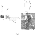
- figure 2 shows a schematic representation of an embodiment of a display device 1 in an application, here as an escape and rescue route sign of a wayfinding system 30.
- the control unit 13 of the display device 1 can receive this signaled with a corresponding activation signal via the interface 13.2, in particular to a communication network 18 and a fire alarm control panel BMZ of the building connected to the communication network.
- the received activation signal can include further activation data based on the present evacuation event.
- the further activation data can contain, for example, image data for optical information to be output by the display device 1 .
- the received activation data can include a memory address for image data stored locally in the memory unit 13.1 of the display device 1 for an icon.
- the activation data can also contain voice data for an acoustic signal to be output by the display device 1 .
- the received activation data can include a memory address for voice data stored locally in the memory unit 13.1 of the display device 1 for an acoustic output.
- the display device 1 uses the optical display unit 4 to show a pictogram 19 on the display medium 5 with a running person and symbolized clouds of smoke.
- the pictogram shown also includes a directional arrow pointing to the right shown above the running person.
- control unit 13 of the display device 1 generates a control signal for driving the means for generating oscillations.
- the means for generating oscillations generates an acoustic signal 20 by means of an oscillation of the optical display unit 4 excited on the basis of the control signal.
- the acoustic signal 20 shown provides the information "Please go to the right. The room behind the left door is filled with smoke.” again. it can be provided that this acoustic output is repeated at regular intervals until an end the emergency situation is recognized. This can be linked to the duration of the display of the pictogram 19 .
- FIG. 12 depicts a simplified block diagram of a preferred embodiment of a dynamic/adaptive routing system 30.
- FIG. The dynamic/adaptive wayfinding system 30 is arranged together with a fire alarm system 40 .
- the arrangement shown comprising the dynamic/adaptive guidance system 30 and the fire alarm system 40 also has a control device 37 .
- the control device 37 can be spatially arranged in a fire alarm control panel BMZ of the fire alarm system 40 .
- the dynamic/adaptive wayfinding system 30 can be, for example, an emergency lighting system of a building.
- the fire alarm system 40 in figure 3 comprises five sensors 41, 42, 43, 44 and 45. Shown are a smoke detector 41, a CO 2 sensor 42 as an example of a gas sensor, a PIR sensor 43, a camera 44 and an acoustic sensor (microphone) 45.
- the Sensors 41 to 45 are connected via communication network 47 to a fire alarm panel BMZ.
- a central control device 46 of the fire alarm system is arranged in the fire alarm control panel BMZ.
- the central control device 46 collects the information from the individual sensors 41 to 45 via the communication network 47. From the information collected from the sensors 41 to 45, the central control device 46 determines a location-based, position-resolved situation image for the area (building) monitored by the sensors 41 to 45 .
- the location-related or position-resolved situation image can include, for example, the report of an assumed fire event (location) in a specific room of the building, ie location-related or position-resolved based on a report from the fire detector 41 located in this room.
- the fire alarm control panel BMZ in figure 3 further comprises the control device 37.
- the control device 37 can be implemented as a logic unit in hardware or as software.
- the central control device 46 of the fire alarm system 40, the control device 37 and an emergency light control unit 36 of the emergency light system/route guidance system 30 can be implemented as software modules on a shared piece of hardware.
- the emergency light control unit 36 controls in the exemplary embodiment according to FIG figure 3 a wayfinding system 30.
- the emergency light control unit 36 can include a logic unit, in particular in the form of software, which is designed to control the display devices 31, 32, 33, 34 and 35 depending on the situation.
- the emergency light control unit 36 is designed to initially control the display device 31 to 35 according to a defined behavior, for example based on a table.
- the dynamic and/or adaptive wayfinding system 30 is designed to direct people to predefined alternative or escape routes in the event of a fire.
- the dynamic and/or adaptive wayfinding system 30 is a self-learning system.
- the wayfinding system 30 is designed as a self-learning system to continuously record and store the behavior of people caused by the system, for example the predefined escape routes and the behavior of people on these escape routes.
- the control device 37 can learn, in particular from a combination of the information collected by the fire alarm system 40 and the emergency light control unit 36, that too many people are being directed onto an escape route, this escape route is consequently overloaded and the risk of mass panic increases.
- the routing system 37 can then divide the flow of people into two or more escape routes. In this way, dynamic escape route guidance, which is also adaptive when the escape routes are adapted during an ongoing emergency event, is made possible by the route guidance system 30 .
- Presence sensors or cameras used for this purpose can be integrated in the display devices 31 to 35 or arranged separately.
- the wayfinding system 30 can also be designed to direct the flow of people through the area with the aim of avoiding congestion.
- the wayfinding system 30 can therefore guide people through museums, direct people to specific goods in a shop or direct vehicles to free parking spaces in a multi-storey car park or in a city.
- the design of the display devices 31 to 35 as display devices 1 according to the invention as part of the dynamic and/or adaptive route guidance system 30 makes it possible to provide location-based acoustic signals, in particular route and direction information in an emergency operating mode, or general acoustic playback, for example speech or music playback in a general set playback mode.
- the sensors 41 to 45 of the fire alarm system 40 can also include mobile devices, in particular cell phones or mobile computers, for example tablet computers or smartphones.
- the mobile devices can be connected to the control device 37 via a communication network, for example a wireless local area network (WLAN) or a cellular mobile radio network, and can transmit position data to the control device 37, for example.
- WLAN wireless local area network
- the control device 37 can identify where people are in the building.
- the control device 37 logically links the information collected from the sensors 41 to 45, the mobile devices and the display devices 31 to 35, in particular the spatial positions of the display devices 31 to 35.
- the control device determines 37 specifications (instructions), which pictograms 19 and which acoustic signals, in particular voice output, should be provided by which display device 31 to 35.
- the control device 37 transmits the corresponding instructions to the emergency lighting control unit 36.
- the emergency lighting control unit 36 then forwards the instructions accordingly for a situation- and position-related optical output and an acoustic output of information through the respective display devices 31 to 35.
- the wayfinding system 30 is designed for navigation, in particular for so-called indoor navigation within buildings.
- the wayfinding system 30 forms an interactive video guide for a museum or for a city.
- a visitor can activate a display device 31 to 35 using an app on a mobile device and this then shows him information or videos about the environment.
- the display devices 31 to 35 can be located, for example, on exhibits in the museum or on historical buildings.
- a parallel installation of optical screens and acoustic reproduction devices with loudspeakers is avoided by using display devices 1 according to the invention.
- the dynamic and/or adaptive routing system 30 can be used to find the way in a shop.
- the wayfinding system 30 can be designed to guide a person with the display devices 31 to 35 in the shop to specific goods.
- Additional display devices 31 to 35 can be located on special goods, which, after activation via an app, display additional information about these goods, e.g. about the production of the goods.
- the control device 37 can use the mobile device assigned to the customer to identify the customer and then send individualized information for a visual display and an acoustic output, for example special customer offers, to a single display device of the plurality of display devices 31 to 35 according to the situation. and transmit position-related.
- the dynamic and/or adaptive wayfinding system 30 is implemented in an office building and, based on sensor data, recognizes whether a workplace or a meeting room is occupied, and a person can use the display devices 31 to 35 to find a free workplace or available meeting room conduct.
- the wayfinding system 30 is installed in a hospital building or the building of a care facility in order to guide people, for example doctors or visitors, to a patient.
- the wayfinding system 30 is implemented in a care facility. For example, if an emergency button is pressed in a care facility, information to calm the patient can be displayed on a display device 31 to 35 in the room, eg "Help is on the way", or a direct connection can be established via video chat with a caregiver. the In this case, the display device 31 to 35 of the emergency lighting system assumes the function of a loudspeaker,
- the display device 31 to 35 can be equipped with a microphone.
- the display device 31 to 35 can handle the entire bidirectional communication between the immediate spatial area of the display device 31 to 35 and a remote station, for example the control device 37, via its correspondingly designed control unit 13 with the interface 13.2.
- a first responder on site in the area of a display device 31 to 35 can receive support during resuscitation from a specialist contact person (doctor, paramedic) via the display device 31 to 35 according to the invention.
- the wayfinding system 30 is installed distributed over the building in connection with a sensor system with optical sensors (camera 44).
- the cameras 44 are also powered in the event of an emergency.
- the camera 44 transmits position-resolved information about the presence of a person in the building to the control device 37, in particular to an interface 37.1 of the control device 37 to the sensor system.
- rescue workers can address a person directly with an acoustic instruction, for example "Please keep calm and stay in the room. Rescue workers with breathing apparatus are on their way to you”.
- the wayfinding system 30 for this application is to be designed with a corresponding transmission option for voice data (acoustic data) through to individually addressable display devices 1, 31 to 35 via the communication network 38.
- the transmission options mentioned via the communication network 38 also enable the operation of the individual display devices 31 to 35 as acoustic playback devices (loudspeakers) in individual rooms or room groups or the entire building in an operating mode independent of an emergency event.
- the routing system 30 is designed with display devices 31 to 35 for displaying timetables, for example at train stations, airports or bus stops. People can have a associated app further, updated timetable information to an acoustic playback and visual display on the display devices 31 to 35 call.
- the overall system is correspondingly favorable with regard to the procurement and installation effort and thus with regard to the costs incurred.
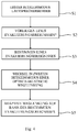
- figure 4 shows a simple flowchart for the operation of a display device 1 according to the invention figure 4 in particular, the two basic operating modes of an embodiment of the display device 1 clearly.
- step S1 the display device 1 is in a first operating mode for the acoustic reproduction of a speech and/or music signal.
- the control unit 13 generates the control signal 15 and outputs the generated control signal 15 to the means for generating oscillations.
- separate amplification means can also be arranged in the signal path in order to adapt the power of the signal to the power requirement for the acoustic output.
- the generated control signal 15 can be an electrical signal modulated with a speech signal or a music signal.
- the generated control signal 15 is an electrical current modulated with the speech or music signal, with which the control unit 13 feeds the electromagnet 11 .
- step S1 the display device 1 works exclusively as a loudspeaker for the acoustic reproduction of music, speech or other noises as an acoustic signal through the display device 1.
- step S2 the control unit 13 checks whether an evacuation event (emergency event) is present.
- Step S2 can be executed at the same time as step S1.
- step S2 can be executed in parallel with step S1 at regular or irregular time intervals.
- control unit 13 can check whether the display device 1 is being fed by the mains power supply 14 in mains operation, or whether the mains power supply 14 has failed and the display device 1 is battery-supported and therefore mains-independent. If mains-independent, battery-supported operation of the display device 1 is present, then the control unit 13 decides that the building needs to be cleared and that an evacuation event is therefore present.
- control unit 13 can be set up to switch from the first operating mode to the second operating mode on the basis of an activation signal supplied externally to the display device 1 .
- step S2 If the control device 13 decides in step S2 that an evacuation event has occurred, the control device 13 can determine the specific evacuation event in step S3. For the application of dynamic routing, this can mean, for example, determining whether the display device 1 should display a specific pictogram 19 for the present evacuation event and output a specific acoustic signal assigned to the pictogram 19 .
- the control device 13 now continues with step S4 and with the action of the display device 1 specified for the specific evacuation event.
- step S4 which follows step S3, the control unit 13 first initiates a change of the display device 1 from the first operating mode to the second operating mode.
- step S4 The change from the first operating mode to the second operating mode of an optical routing takes place in step S4.
- the control unit 13 can in particular read in image data for the display of a specific pictogram 19 from the memory unit 13.1. Furthermore, the control unit 13 can read in stored acoustic data corresponding to the specific pictogram 19 for the acoustic reproduction by the display device 1 .
- step S5 the control unit 13 generates the control signal 15 on the basis of the acoustic data read in and sends this control signal to the vibration-generating means.
- step S5 the display device 1 now works in the second operating mode, in which at the same time as the optical output Pictogram 19 corresponding to the read-in image data on the display medium 5, the acoustic output of the pictogram 19 assigned acoustic signal 20 by means of corresponding vibrational excitation of the optical display unit 4 takes place.
- the display device 1 thus implements a “dual mode” operation.
- the display device 1 can also be used as a purely acoustic reproduction means in one of the operating modes.
- the control device 37 can have an interface 37.2 via which data for the acoustic output, in particular music data and/or voice data, can be read.
- the read-in data can be processed in the control device 37 .
- the processed data can be forwarded via the communication network 38 to the individual display devices 31 to 35 for the acoustic output. This means that the separate and additional construction of a network for additional loudspeakers for the output of acoustic signals is just as unnecessary as additional loudspeakers for the display devices 31 to 35.
- the first operating mode enables the creation of a distributed loudspeaker system, which is made possible with minimal additional effort in the area of the emergency light control unit 36 and the control device 37 by means of the display devices 1, 31 to 35 according to the invention. Since escape route lights are located at every exit door (escape route) around the room in a hall-like room, the room can be exposed to sound from different sides. An effect comparable to “Dolby Surround” can thus be achieved by including the display device according to the invention in a system for sound reinforcement of the room. The technical outlay and thus the combined costs for escape route identification and guidance and sound reinforcement of the room are thus advantageously reduced by means of the display device 1 according to the invention.
Landscapes
- Engineering & Computer Science (AREA)
- Physics & Mathematics (AREA)
- General Physics & Mathematics (AREA)
- Theoretical Computer Science (AREA)
- Business, Economics & Management (AREA)
- Multimedia (AREA)
- Emergency Management (AREA)
- Accounting & Taxation (AREA)
- Marketing (AREA)
- General Engineering & Computer Science (AREA)
- Alarm Systems (AREA)
- Audible And Visible Signals (AREA)
Abstract
Description
- Die Erfindung betrifft das Gebiet der Wegelenkung für Personen, insbesondere der Fluchtweglenkung. Es wird eine Anzeigevorrichtung für Gebäude, sowie ein entsprechendes Wegeleitsystem und eine Anordnung, die das Wegeleitsystem und ein Sensornetzwerk umfasst, vorgeschlagen.
- Sicherheitsbeleuchtung mit Notleuchten ermöglicht es Personen, ein Gebäude oder ein Areal in einer Notsituation, wie beispielsweise einem Brand, schnell und sicher zu verlassen oder sichere Bereiche des Gebäudes aufzusuchen.
- In entsprechend ausgestatteten Gebäuden oder Arealen sind Fluchtweganzeigen mit Piktogrammen angeordnet, die eine räumliche Fluchtweglenkung bei Eintritt einer solchen Notsituation bewirken sollen. Fluchtweganzeigen sollen auch bei einer Störung der allgemeinen elektrischen Beleuchtung des Gebäudes sichtbar sein und daher oftmals mit Notleuchten integriert ausgeführt.
- Ein Beispiel für Fluchtweganzeigen sind Schilder mit Piktogrammen oder besondere Fluchtweganzeigeleuchten, mit denen Personen die Richtung eines Flucht- oder Rettungswegs zum Verlassen des Gebäudes oder Areals angezeigt wird.
- Die Piktogramme können als statische Fluchtweganzeigen auf Schildern aufgebracht sein.
- Fluchtweganzeigeleuchten können beleuchtete Piktogramme umfassen, die als aktive Fluchtweganzeigen bei Eintritt (Feststellen) eines Notfallereignissen aktiviert werden.
- Piktogramme als Anzeigen sind bildliche Darstellungen einer Information, die eine stilisierte, laufende Person und einen Pfeil in Richtung eines vorab festgelegten Fluchtwegs zeigen. Die Piktogramme können alternativ oder zusätzlich andere Zeichen umfassen, beispielsweise den Schriftzug "EXIT".
- Ein Problem dieser bekannten Systeme ist, dass Personen durch die statischen Piktogramme in eine Gefahrensituation, beispielsweise in einen verrauchten Raum, geleitet werden können. Es sind daher dynamische Fluchtweganzeigen entwickelt worden, bei denen ein Teil der Fluchtweganzeigen als veränderbare Anzeige ausgebildet sind. Mit diesen veränderbaren Anzeigen wird ein Pfeil in Richtung des Flucht- und Rettungsweges dargestellt, wobei die Pfeilrichtung durch entsprechende Ansteuerung der Anzeige einstellbar ist. Die Ansteuerung einer solchen dynamischen Fluchtweganzeige kann beispielsweise abhängig von den in einer Brandmeldezentrale (BMZ) des Gebäudes zusammenlaufenden Daten von Brandmeldern erfolgen. Solche dynamischen Fluchtwegeanzeigen finden im Rahmen von System zur dynamischen oder adaptiven Fluchtweglenkung Verwendung, wie sie insbesondere auch in dem Merkblatt 33013:2016-05 des ZVEI Zentralverband der Elektrotechnik- und Elektronikindustrie e. V., Fachverband Sicherheit, im Mai 2016 mit dem Titel "Adaptive Fluchtweglenkung: Weiterentwicklung der der technischen Gebäudeevakuierung: Von der Dynamischen zur Adaptiven Fluchtweglenkung" (https://www.zvei.org/fileadmin/user_ _upload/ Presse_und_Medien/Publikationen/20i6/mai/Adaptive_Fluchtweglenkung_-_ZVEI-Merkblatt_333013_20i6-05/MerkBlatt-33013-2016-05_Adaptive_Fluchtweglenkung.pdf) vorgestellt werden.
- Die bekannten dynamischen Fluchtweganzeigen zeigen jedoch Nachteile. Die Wirksamkeit derartiger optischer Fluchtweganzeigen beruht allein auf der optischen Wahrnehmung der gezeigten Piktogramme durch Personen, die sich in einem Bereich um die Fluchtweganzeige aufhalten.
- Bei starker Rauchentwicklung im Inneren eines Gebäudes kann die Sichtweite eingeschränkt sein, insbesondere bei über der Kopfhöhe durchschnittlich großer Personen und damit möglicherweise in unmittelbarer Höhe einer Raumdecke angebrachten Fluchtweganzeigen. Personen mit Seheinschränkungen, beispielsweise Blinde, Personen mit altersbedingten Seheinschränkungen erkennen die Piktogramme bereits ohne zusätzliche Behinderung durch Rauch nicht oder nur sehr eingeschränkt.
- Europäische und nationale Normen schreiben vor, dass Menschen mit Behinderung nicht benachteiligt werden dürfen. Somit müssen Menschen mit sensorischen Einschränkungen, beispielsweise mit einer Sehbehinderung, durch das zwei-Sinne-Prinzip (2-Kanal-Prinzip) in ihren Möglichkeiten zur Selbstrettung verbessert werden. Dabei werden für die Zwecke der Fluchtweglenkung die zwei Sinne "Sehen" und "Hören" der drei Sinne "Sehen", "Hören" und "Tasten" genutzt. Nach dem zwei-Sinne-Prinzip kann eine Alarmauslösung und Fluchtweglenkung mittels optischer und akustischer Vorrichtungen erfolgen. Als akustische Alarmierungsgeräte sind akustische Signalgeber sind Lautsprecher bekannt, die bei Eintritt eines Evakuierungsereignisses akustische Signale, beispielsweise gespeicherte Sprachdateien abspielen, dass das Gebäude verlassen werden soll. Ein entsprechendes zusätzlich eingerichtetes Lautsprechersystem, das auch bei Eintritt eines entsprechenden Ereignisses, möglicherweise verbunden mit Ausfall der Netzstromversorgung, für einen vordefinierten Zeitraum voll funktionsfähig ist, ist jedoch mit zusätzlichen Kosten verbunden.
- Über eine bekannte, akustische Alarmierung hinaus, ist es wünschenswert, dass Personen mit Seheinschränkungen beispielsweise durch akustische Signale, im bei Eintritt eines Notereignisses laufend unterstützt werden, um das Gebäude oder Gelände so schnell als möglich verlassen zu können.
- Es ist daher eine Aufgabe der vorliegenden Erfindung, ein verbessertes Wegeleitsystem zur dynamischen und/oder adaptiven Wegeleitung bereitzustellen, welche die oben genannten Nachteile des Standes der Technik beseitigen.
- Diese Aufgabe, wird durch eine Anzeigevorrichtung mit den Merkmalen nach Anspruch 1, ein Wegeleitsystem sowie eine Anordnung aus einem Wegeleitsystem und einem Sensornetzwerk gemäß den unabhängigen Ansprüchen gelöst.
- Gemäß einem ersten Aspekt betrifft die Erfindung eine Anzeigevorrichtung, die eine optische Anzeigeeinheit und einen Gehäuserahmen umfasst. Die optische Anzeigeeinheit ist für die Anzeige eines Piktogramms ausgelegt. Die Anzeigevorrichtung ist dadurch gekennzeichnet, dass die optische Anzeigeeinheit an dem Gehäuserahmen elastisch gelagert und relativ zu dem Gehäuserahmen zu mechanischen Schwingungen anregbar ist. Weiter weist die erfindungsgemäße Anzeigevorrichtung ein schwingungserzeugendes Mittel auf. Das schwingungserzeugende Mittel ist dafür ausgelegt, auf Basis eines Steuersignals die optische Anzeigeeinheit zu mechanischen Schwingungen für die Wiedergabe eines akustischen Signals in einem für den Menschen wahrnehmbaren Frequenzbereich anzuregen.
- In der erfindungsgemäßen Anzeigevorrichtung ist die akustische Signalausgabe direkt integriert. Besonders vorteilhaft hinsichtlich des Aufbaus der Anzeigevorrichtung ist dabei die optische Anzeigeinheit für die optische Darstellung des Piktogramms zugleich als akustischer Signalgeber, insbesondere als dessen Schallfläche zu nutzen. Damit kann auf einen Lautsprecher als isoliertes Bauelement verzichtet werden. Optische und akustische Fluchtweglenkung sind darüber hinaus in einer einzigen Anzeigevorrichtung besonders vorteilhaft integriert.
- Die erfindungsgemäße Anzeigevorrichtung ermöglicht es, ein System zur dynamischen Fluchtweglenkung so umzusetzen, das ein dynamisches optisch wahrnehmbares Rettungszeichen und eine dynamische akustische Fluchtweglenkung in Kombination bereitstellt. Studien zeigen, dass Personengruppen ohne visuelle Einschränkung durch ergänzende akustischen Durchsagen sich schneller in einem ihnen unbekannten Gebäuden orientieren, und das Gebäude verlassen können, in bestimmten Fällen in einer um 50 bis 70% kürzeren Zeit.
- Die erfindungsgemäße Anzeigevorrichtung bewirkt verringerte Herstellungskosten für den Hersteller, sowie reduzierte Beschaffungskosten und Systemkosten für den Kunden. Es realisiert ein Produkt Anzeigevorrichtung beide Funktionen - optische Anzeige und akustische Anzeige einer entsprechenden Information -, womit für ein Wegeleitsystem der gleichen Funktionalität weniger Komponenten zu beschaffen, zu montieren und zu einem System zu integrieren sind.
- Der Aufbau der Anzeigevorrichtung selbst ist deshalb besonders vorteilhaft, da die Komponente optische Anzeigeeinheit für die Bereitstellung zweier Funktionen - optische Anzeige und akustische Anzeige einer entsprechenden Information - wesentliche Aufgaben übernimmt. Die optische Anzeigeeinheit dient unmittelbar der optischen Anzeige des Piktogramms, zugleich wird die Funktion einer Lautsprechermembran für die akustische Ausgabe desakustischen Signals übernommen.
- Die abhängigen Ansprüche bilden den zentralen Gedanken der Erfindung in vorteilhafter Weise weiter.
- Die Anzeigevorrichtung nach einer Ausführungsform weist eine Steuereinheit zur Erzeugung und Ausgabe eines Steuersignals an das schwingungserzeugende Mittel der Anzeigevorrichtung auf.
- Damit kann die Anzeigevorrichtung die optische Anzeigeeinheit als Membran eines Schallwandlers nutzen, der aus dem zugeführten (elektrischen) Steuersignal ein akustisches Schallsignal in einem für Personen wahrnehmbaren Frequenzbereich erzeugt und an die Umgebung abgibt. Die Anordnung der Steuereinheit in der Anzeigevorrichtung ermöglicht zugleich eine lokale Steuerung und aufeinander abgestimmte Steuerung der Ausgabe optischer und akustischer Information an einer Position.
- Gemäß einer Ausführungsform der Anzeigevorrichtung umfasst die Anzeigevorrichtung Speichermittel eingerichtet zur Speicherung zumindest eines vordefinierten akustischen Signals zugeordnet zu dem Piktogramm. Das akustische Signal kann als Steuersignal zur Ausgabe an die schwingungserzeugenden Mittel gespeichert sein. Alternativ oder zusätzlich weist die Anzeigevorrichtung eine Schnittstelle ausgelegt zum Einlesen des vordefinierten akustischen Signals zugeordnet zu dem Piktogramm auf. Die Steuereinheit der Anzeigevorrichtung ist eingerichtet, das gespeicherte und/oder eingelesene vordefinierte akustischen Signal in Abhängigkeit von einer räumlichen Position der Anzeigevorrichtung und/oder situationsabhängig in dem Steuersignal an die schwingungserzeugenden Mittel auszugeben, und das zugeordnete Piktogramm durch die optische Anzeigevorrichtung sichtbar anzuzeigen.
- Die Anzeigevorrichtung in einer weiteren Ausführungsform umfasst die Steuereinheit, die dazu eingerichtet ist, die schwingungserzeugenden Mittel mit dem Steuersignal zumindest in einem ersten Betriebsmodus zur akustischen Wiedergabe eines Sprach- und/oder Musiksignals anzusteuern, und in einem zweiten Betriebsmodus mit dem Steuersignal für eine akustische Ausgabe des dem Piktogramm zugeordneten akustischen Signals anzusteuern und zugleich eine optische Ausgabe des Piktogramms über die optische Anzeigeeinheit zu bewirken.
- Gemäß einer Ausführungsform umfasst die Anzeigevorrichtung die Steuereinheit eingerichtet dafür, die schwingungserzeugenden Mittel in dem ersten Betriebsmodus anzusteuern, wenn die Steuereinheit einen Betrieb der Anzeigevorrichtung in einem Netzbetrieb, also gespeist von einer Netzstromversorgung, erkennt. Die Steuereinheit ist weiter dafür ausgelegt, die schwingungserzeugenden Mittel in dem zweiten Betriebsmodus anzusteuern, wenn die Steuereinheit einen netzunabhängigen, batteriegestützten Betrieb der Anzeigevorrichtung erkennt. Ein batteriegestützter Betrieb wird somit als Indiz für einen Ausfall der Netzstromversorgung und damit auch als Hinweis auf den Eintritt eines Notfallereignisses gewertet. Alternativ oder zusätzlich kann die Steuereinheit dafür eingerichtet sein, zwischen dem ersten Betriebsmodus und dem zweiten Betriebsmodus auf Basis eines der Anzeigevorrichtung extern zugeführten Signals zu wechseln. Dies kann beispielsweise mittels eines über eine DALI-Schnittstelle der Anzeigevorrichtung, insbesondere deren Steuereinheit zugeführtes Aktivierungssignals erfolgen.
- Die Anzeigevorrichtung kann als das schwingungserzeugende Mittel einen Magneten und einen mit dem Steuersignal gespeisten Elektromagneten umfassen.
- Gemäß einer Ausführungsform der Anzeigevorrichtung weist die optische Anzeigeeinheit einen flächig ausgebildeten Anzeigeträger und ein parallel dazu angeordnetes Beleuchtungsmittel auf. Das Beleuchtungsmittel ist dabei als Lichtleiter, bevorzugt als Lichtleiterplatte, ausgebildet und in Betrachtungsrichtung vor dem Anzeigeträger angeordnet, um eine Vordergrundbeleuchtung des Anzeigeträgers zu ermöglichen. Der durch das Beleuchtungsmittel beleuchtete Anzeigeträger zeigt das Piktogramm in die Betrachtungsrichtung, ohne das Komponenten der Anzeigevorrichtung eine störende Schattenbildung bewirken.
- Die Anzeigevorrichtung einer weiteren Ausführungsform nutzt als Anzeigetechnologie für die optische Anzeigeeinheit elektronisches Papier, um das Piktogramm sichtbar darzustellen. Bevorzugt stellt das Piktogramm eine dynamisch und/oder adaptiv änderbare Wegeinformation und/oder Richtungsinformation dar.
- Die Nutzung elektronischen Papiers als Anzeigetechnologie ermöglicht die Verwirklichung einer dynamischen Anzeige des Piktogramms. Elektronisches Papier, auch gelegentlich bezeichnet mit der englischen Übersetzung "E-Paper Display", den dazu synonym verwendeten Begriffen "E-Ink", "eInk" oder "E Ink™" erreicht als Anzeigetechnologie für Bildschirme, dass eine dynamische Anzeige geschaffen wird, die eine eingestellte Abbildung auch bei vollständigem Ausfall einer Energieversorgung weiterhin anzeigt. Insbesondere ist elektronisches Papier ein Beispiel für eine bistabile Anzeige, die lediglich zur Ändern der Anzeige eine Energieaufnahme in Form eines elektrischen Stroms benötigt. Dies ist für einen batteriegestützten Betrieb bei Eintritt eines Notereignisses mit Ausfall einer Netzstromversorgung besonders vorteilhaft.
- Elektronisches Papier zeigt den weiteren Vorteil, dass die so realisierte Anzeige die wesentlichen Eigenschaften einer klassischen Beschilderung zeigt. Bestehende Normen und Empfehlungen für das Erscheinungsbild von Sicherheitsanzeigen können mittels diesen Anzeigetyps einfach erfüllt werden. Dies gilt insbesondere auch für eine Farbdarstellung. Aufgrund eines geringen Abstands der bildgebenden Elemente zur Oberfläche der optischen Anzeigeeinheit ist der wiedergegebene Anzeigeinhalt aus einem weiten Blickwinkelbereich gleich aussehend und gut erkennbar. Der Inhalt der optischen Anzeige wird flimmerfrei dargestellt und ist gleichermaßen bei Kunstlicht, also beispielsweise einem beleuchteten Raum, oder Sonnenlicht erkennbar. Elektronisches Papier ist in unterschiedlichen Größen verfügbar, mit geringer Dicke und daher gewichtsmäßig leicht herzustellen und kann in biegsamen und festen Ausführungen ausgebildet werden. aufgrund des geringen Gewichts und der damit verbundenen geringen Massenträgheit eignet sich eine solche Anzeigeeinheit besonders für die erfindungsgemäße Anzeigevorrichtung.
- Die Anzeigevorrichtung einer bevorzugten Ausführungsform ist als Fluchtweganzeige ausgelegt.
- Die Anzeigevorrichtung ist mit ihrer Fähigkeit, gleichermaßen akustisch wie optisch Informationen auszugeben, besonders für den Betrieb bei Eintritt von Notfallereignissen unter Nutzung des "Zwei-Sinne-Prinzips" geeignet. Personen in Stresssituationen werden zuverlässig mit wesentlichen Informationen über ihre optischen und akustischen Sinne versorgt. Dabei hat eine akustische Ausgabe durch dieselbe Vorrichtung, die auch die optische Anzeige darstellt, den Vorteil, dass die Aufmerksamkeit von Personen in Richtung der Anzeige gelenkt wird. Dabei wird genutzt, dass der Mensch eine Richtung im Raum zu einer Schallquelle orten kann.
- Gemäß einem zweiten Aspekt betrifft die Erfindung ein Wegeleitsystem mit zumindest einer Anzeigevorrichtung nach dem ersten Aspekt der Erfindung. Die zumindest eine Anzeigevorrichtung ist in einen räumlichen Bereich verteilt angeordnet und mittels eines Kommunikationsnetzes des Wegeleitsystems vernetzt. Eine Steuervorrichtung des Wegeleitsystems ist dazu eingerichtet, jeweils die zumindest eine Anzeigevorrichtung individuell zur Ausgabe eines positionsbezogenen akustischen Signals und des entsprechend zugeordneten Piktogramms anzusteuern.
- Die erfindungsgemäße Anzeigevorrichtung ermöglicht damit die Konzeption eines besonders vorteilhaften Wegeleitsystems, da zur Verwirklichung einer dynamischen akustischen Weglenkung die akustischen Signale genau dort bereitgestellt werden, wo sie gebraucht werden: an jeder bezeichneten Wegänderung. Somit können dadurch lokal relevante, dynamische Durchsagen, wie beispielsweise "gehen Sie nach links", "gehen Sie nach rechts" für Personen bereitgestellt werden, wo sie besonders zweckmäßig sind.
- Gemäß einem dritten Aspekt betrifft die Erfindung eine Anordnung umfassend das Wegeleitsystem gemäß dem zweiten Aspekt und ein Sensorsystem, wobei das Wegeleitsystem und die Sensoren des Sensorsystems über den räumlichen Bereich verteilt angeordnet sind. Die Steuervorrichtung weist eine Schnittstelle auf, die dafür eingerichtet ist, positionsbezogene Sensordaten einzulesen.
- Die Anordnung gemäß einer Ausführungsform weist ein Sensorsystem auf, das zumindest einen Sensor aufweist, der als Brandmelder, einen Rauchwarnmelder ausgebildet ist, sowie einen Bewegungsmelder, einen Präsenzsensor, Temperatursensor, einen abbildenden Sensor, insbesondere auch Kamerasensor, einen Gassensor, insbesondere auch CO2-Sensor, oder akustischen Sensor unter seinen Sensoren.
- Eine Ausführungsform der Anordnung umfasst die Steuervorrichtung, ausgebildet mit einer Sprachschnittstelle zu einem Mikrofon. Die Steuervorrichtung ist dabei eingerichtet, über die Sprachschnittstelle aufgenommene oder gespeicherte Sprachsignale an die Steuereinheiten der zumindest zwei Anzeigevorrichtungen des Wegeleitsystems auf Basis zumindest einer durch das Sensorsystem ermittelten Positionsinformation zu übertragen.
- Nachfolgend werden Ausführungen der Erfindung anhand einer kurze Beschreibung der Figuren diskutiert. Es zeigt
- Figur 1
- eine Übersicht über Funktionsblöcke einer bevorzugten Ausführungsform einer erfindungsgemäßen Anzeigevorrichtung eines Wegeleitsystems,
- Figur 2
- eine schematische Darstellung einer Ausführungsform einer Anzeigevorrichtung in einem Anwendungsfall,
- Figur 3
- eine schematische Darstellung einer bevorzugten Ausführungsform einer Anordnung eines dynamischen /adaptiven Wegeleitsystems mit einem Sensorsystem, und
- Figur 4
- ein einfaches Ablaufdiagramm des Betriebs einer erfindungsgemäßen Anzeigevorrichtung in einem Dual-Mode-Betrieb,
- Im Folgenden wird eine besonders bevorzugte Ausführungsform anhand einer Anzeigevorrichtung 1 ausgebildet als ein Flucht- oder Rettungswegschild innerhalb eines Wegeleitsystems 30 eines räumlichen Bereichs, insbesondere eines Gebäudes und dessen Umfelds vorgestellt. Das Wegeleitsystem 30 kann eine Notbeleuchtung, eine Sicherheitsbeleuchtung, eine Rettungswegbeleuchtung und/oder Rettungswegzeichen umfassen.
-
Figur 1 gibt eine Übersicht über Funktionsblöcke einer erfindungsgemäßen Anzeigevorrichtung 1. - Die wenigstens eine Anzeigevorrichtung 1 des Wegeleitsystems kann ein Flucht- oder Rettungswegschild bilden. Die Anzeigevorrichtung 1 kann an einer Wand oder an einer Decke des Gebäudes angeordnet sein. Die Anzeigevorrichtung 1 umfasst einen Gehäuserahmen 4, in und/oder an dem weitere Baugruppen und Einheiten der Anzeigevorrichtung 1 angeordnet sind.
- Die dargestellte Anzeigevorrichtung 1 weist eine mit dem Gehäuserahmen 2 fest verbundene Aufhängevorrichtung 3 auf. Die Aufhängevorrichtung 3 zeigt eine flach ausgebildete Anlagefläche für eine Wandmontage der Anzeigevorrichtung 1. Die Aufhängevorrichtung 3 kann Befestigungsmöglichkeiten für eine Wandmontage oder für eine Aufhängung mittels Seilen, Ketten o. ä. von einer Decke umfassen.
- In der Anzeigevorrichtung 1 ist die akustische Fluchtweglenkung direkt integriert. Zentrales Element der erfindungsgemäßen Anzeigevorrichtung 1 ist es, eine optische Anzeigeeinheit 4 selbst für die Schallerzeugung und somit als akustischer Signalerzeuger und schallerzeugende Fläche zu nutzen.
- Innerhalb des Gehäuserahmens 2 sind die einzelnen Komponenten und Baugruppen der Anzeigevorrichtung 1 angeordnet. Eines dieser Elemente ist die optische Anzeigeeinheit 4. Die optische Anzeigeeinheit 4 umfasst einen Anzeigeträger 5, der eine Anzeigefläche für die Darstellung des Piktogramm 19 aufweist. Der Anzeigeträger 5 ist so in dem Gehäuserahmen 2 angeordnet, dass die Anzeigepflicht mit dem Piktogramm 19 in zumindest einer Betrachtungsrichtung (Frontseite) für einen Betrachter sichtbar angeordnet ist. Die Größe der Fläche des Anzeigeträgers 5 in Betrachtungsrichtung ist dabei vorzugsweise durch die Größe des darzustellenden Piktogramms 19 vorgegeben.
- Piktogramme 19 kommen in unterschiedlichen Größen, je nach erforderlicher Erkennungsreichweite vor. Die Erkennungsreichweite kann üblich durch Multiplikation einer Höhe des Piktogramms mit einem Faktor mit dem Wert 200 errechnet werden. Für übliche Piktogrammgrößen ergeben sich damit bespielsweise folgende Erkennungsreichweiten:
- (1) für 75 x 150mm beträgt die Erkennungsreichweite 15 Meter,
- (2) für 115 x 230mm beträgt die Erkennungsreichweite 23 Meter, und
- (3) für 150 x 300mm beträgt die Erkennungsreichweite 30 Meter.
- Bei einer typischen Piktogrammgröße für eine Erkennungweite von 30 m stehen somit 450 cm2 Piktogrammfläche als schallerzeugende Fläche für die Nutzung im Rahmen der ererfindungsgemäßen Anzeigevorrichtung 1 zu Verfügung.
- Der Anzeigeträger 5 kann insbesondere als ein Bildschirm unter Nutzung der Anzeigetechnologie elektronisches Papier ausgebildet sein. Elektronisches Papier reflektiert Licht wie Papier und zeigt damit den Effekt einer passiven, damit nichtleuchtenden, Anzeige. Der Bildinhalt, hier ein Piktogramm 19, kann dauerhaft angezeigt werden, ohne dass eine Energiezufuhr zur Aufrechterhaltung der Anzeige erforderlich ist. Damit ist eine Nutzung für Notleuchten besonders vorteilhaft. Die Möglichkeit der Anzeigetechnologie elektronisches Papier ermöglicht zusätzlich eine dynamsiche Änderung der Anzeige während eines Betriebs in einer Notsituation. Damit kann der mittels dieser Anzeigetechnologie aufgebaute Anzeigeträger 5 insbesondere eine dynamische und/oder adaptive Anzeige von Piktogrammen 19 realisieren.
- In einer Betrachtungsrichtung 18 ist dem Anzeigeträger 5 ein Beleuchtungsmittel 6 vorgelagert. Das Beleuchtungsmittel 6 umfasst in dem Ausführungsbeispiel nach
Figur 1 einen plattenförmig ausgebildeten Lichtleiter 7 sowie eine oder mehrere Leuchtdioden 8 (LED) als Leuchtmittel zum Einkommen von Licht in den Lichtleiter 7. - Bekannte Anzeievorrichtungen weisen Leuchtmittel auf, die einen Anzeigeträger mit dem Piktogramm 19 von hinten, also von der von einem Betrachter abgewandten Seite, beleuchten.
- Die Anzeigevorrichtung 1 nach
Figur 1 weist demgegenüber eine Frontbeleuchtung durch ein in Betrachtungsrichtung 18 angeordnetes Beleuchtungsmittel 6 auf, also auf einer dem Betrachter zugewandten Seite des Anzeigeträgers 5 mit dem Piktogramm 19. Das dargestellte Beleuchtungsmittel 6 umfasst dazu im wesentlichen den planar ausgebildeten Lichtleiter 7. Die gezeigte Ausführung der optischen Anzeigeeinheit 4 zeigt eine, alternativ auch mehrere, LED 8 entlang einer Seite des im Wesentlichen rechteckig ausgebildeten Lichtleiters 7. Die LED 8 sind derart angeordnet, dass das von ihnen abgegebenen Licht in den Lichtleiter 7 eingekoppelt und im Lichtleiter 7 geführt und gestreut wird. Das Licht der LED 8 verwirklicht damit eine Frontbleuchtung des Anzeigeträgers 5 mit dem darauf dargestellten Piktogramm 19. Damit kann eine normgerechte Beleuchtung des Piktogramms 19 verwirklicht werden, wie dies insbesondere im Anwendungsfall einer Notleuchte, einer Sicherheitsleuchte oder einer Flucht- und Rettungswegkennzeichnung regelmäßig vorgeschrieben ist. - Bei der dargestellten Anzeigevorrichtung 1 können die zur Realisierung des Schallwandlers (Lautsprechers) in Betrachtungsrichtung 18 hinter dem Anzeigeträger 5 angeordneten Elemente Magnet 12, Elektromagnet 11 und Betriebsgerät 13 den Lichtweg der Beleuchtung nicht beinflussen, da die Anzeigevorrichtung 1 eine Frontbeleuchtung durch das Beleuchtungsmittel 6 realisiert. Ein Schattenwurf durch die Elemente des Schallwandlers tritt somit nicht auf. Das gezeigte Piktogramm 19 kann normkonform ausgeleuchtet werden.
- Die Ausführungsform nach
Figur 1 ordnet weiter eine lichtdurchlässige Frontabdeckung 9 in Betrachtungsrichtung vor dem Lichtleiter 7 des Beleuchtungsmittels 6 an. - Damit umfasst die optische Anzeigeeinheit 4 den Anzeigeträger für den Lichtleiter 7, die LED 8 und die Frontplatte 9 als fest miteinander verbundene Komponenten. Komponenten der optischen Anzeigeeinheit 4 verwirklichen, angesteuert von einer Steuereinheit 13 eine beleuchtetbare optische Anzeige für das Piktogramm 19.
- Alternativ könnte jedoch auch nur ein Teil der Elemente der Anzeigeeinheit 4 zum schwingen angeregt werden.
- Die optische Anzeigeeinheit 4 ist in dem Gehäuserahmen 2 elastisch und damit schwingungsfähig gelagert. Diese elastische, schwingungsfähige (schwingbare) Lagerung erfolgt durch die elastischen Befestigungsmitteln 10. Als elastische Befestigungsmittel 10 können beispielsweise eine Membran oder federnde Befestigungsmittel zwischen dem Gehäuserahmen 2 und der optischen Anzeigeeinheit 4 angeordnet sein.
- Die elektrische Ansteuerung der schwingungsfähigen optischen Anzeigeeinheit 4 zugeordneten LED 7 ausgehend von der Steuereinheit 13 erfolgt über ein flexible elektrische Verbindung 17. Da eine möglichen maximalen Auslenkung der optischen Anzeigeeinheit 4 gering ist, ist die flexible elektrische Verbindung mittels eines mehradrigen, insbesondere eines 2-adrigen flexiblen Kabels möglich.
- Die flexible elektrische Verbindung 17 kann eine erste elektrische Verbindung 17.1 für die Versorgung der LED 8 mit einem LED-Strom und eine zweite elektrische
- Verbindung 17.2 für die Ansteuerung des Anzeigeträgers 5 umfassen. Die Ansteuerung des Anzeigeträgers 17.2 kann die Übertragung von Bilddaten für die Darstellung des Piktogramms 19 ausgehend von der Steuereinheit 13 ermöglichen. Alternativ oder zusätzlich kann der Anzeigeträger 5 Bilddaten für zumindest ein Piktogramme 19 speichern.
- Die in dem Gehäuserahmen 2 angeordnete Steuereinheit 13 erzeugt weiter ein Steuersignal (elektrisches Steuersignal 15) zur Ansteuerung von schwingungserzeugenden Mitteln der Anzeigeeinheit 1. Die Ausführungsform nach
Figur 1 zeigt schwingungserzeugenden Mittel, die einen mit dem Gehäuserahmen 2 fest verbundenen Elektromagneten 11 und einen mit der optischen Anzeigeeinheit 4 fest verbundenen Permanentmagneten 12 aufweisen. Der Elektromagnet 11 und der Permanentmagnet 12 sind zueinander derart angeordnet, dass mittels des dem Elektromagneten 11 zugeführten Steuersignals 15 eine anziehende und/oder abstoßende Kraft zwischen dem Elektromagnet 11 und im Permanentmagnet 12 erzeugt werden kann. - Die Ausbildung der schwingungserzeugenden Mittel mittels eines mit dem Gehäuserahmen 2 fest verbundenen Elektromagnet 11 und eine mit der optischen Anzeigeeinheit 4 fest verbunden Permanentmagnet 12 stellt lediglich eines von vielen möglichen Ausprägungen für die schwingungserzeugenden Mittel dar.
- Beispielsweise kann der Elektromagnet 11 auch als Tauchmagnet fest mit der optischen Anzeigeeinheit 4 verbunden sein, und in einen entsprechend geformten Permanentmagneten 11 angeordnet in starrerer Verbindung mit dem Gehäuserahmen 2 eintauchen.
- Alternativ können als schwingungserzeugendes Mittel auch andere, grundsätzlich bekannte technische Lösungen aus dem Gebiet der Schallwandler zum Einsatz kommen. So kann der Antrieb des Lautsprechers mittels schwingungserzeugender Mittel auch unter Nutzung piezoelektrischer oder elektrostatischer Effekte verwirklicht werden.
- Die Komponenten der erfindungsgemäßen Anzeigevorrichtung 1 verwirklichen dabei die wesentlichen Eigenschaften eines Schallwandlers. Der Schallwandler ist als Lautsprecher ausgelegt für die Schallerzeugung zur Wiedergabe von Sprache und/oder Musikin einem für den Menschen hörbaren Frequenzbereich von 20 Hz bis hin zu 20 kHz: die optische Anzeigeeinheit 4 erfüllt dabei die Funktion der Lautsprechermembran, das schwingungserzeugende Mittel die Funktion der Antriebseinheit des Lautsprechers und die elastischen Befestigungsmittel 9 die Funktion der verbindenden Elemente bezüglich Lautsprechermembran und Lautsprechergehäuse. In dem in
Figur 1 dargestellten Fall wird somit mittels des Steuersignals 15 an die schwingungserzeugenden Mittel die optische Anzeigeeinheit 4 in eine Schwingung versetzt. Die optische Anzeigeeinheit 4 bewegt sich damit in Abhängigkeit von einer Frequenz des Steuersignals 15 kolbenartig in Relation zu den Gehäuserahmen 2. - Die technsichen Parameter der schwingungserzeugenden Mittel, beispielsweise ein Durchmesser und eine Wicklungshöhe eine den Elektromagneten 11 verwirklichenden Spule, ebenso wie die Stärke und Reichweite eines Magnetfeldes des Permanentmagneten 12 sind entsprechend den gewünschten Leistungsparametern des durch die erfindungsgemäße Anzeigevorrichtung 1 verwirklichten Lautsprechers zu dimensionieren.
- Die Steuereinheit 13 der Anzeigevorrichtung 1 erzeugt das Signal zur Ansteuerung der Beleuchtungsmittel, in
Figur 1 der LED 87, als auch das Steuersignal 15 für den Ansteuerung der schwingungserzeugenden Mittel, im gezeigten Ausführungsbeispiel des Elektromagneten 11. Damit steuert die Steuereinheit 13 sowohl die optische Anzeige des Piktogramms 19 durch die Beleuchtungsmittel 6, als auch eine akustische Ausgabe einer dem Piktogramm 19 zugeordneten Information über das Steuersignale 15. - Die Steuereinheit 13 verfügt in einem Ausführungsbeispiel über eine Speichereinheit 13.1. Die Speichereinheit 13.1 kann ein oder mehrere Piktogramme 19 jeweils in Form von Bilddaten, sowie akustische Ausgabedaten, insbesondere Sprachdaten, speichern.
- Insbesondere kann die Speichereinheit 13.1 Piktogramme 19 zugeordnet zu entsprechenden akustischen Ausgabedaten speichern.
- Bevorzugt speichert die Speichereinheit 13.1 ein oder mehrere Piktogramme 19, wobei jedem als Bilddatei gespeicherten Piktogramm 19 eine oder mehrere entsprechende akustische Ausgabedateien zugeordnet gespeichert sind.
- Besonders bevorzugt speichert die Speichereinheit 13.1 zumindest ein Piktogramm 19 mit einer Weginformation und/oder Richtungsinformation als Bilddaten für die optische Anzeige, sowie zugeordnet zu diesem Piktogramm 19 die entsprechende Weginformation und/oder Richtungsinformation in Form einer einer Sprachdatei für eine akustische Ausgabe der Weginformation und/oder Richtungsinformation.
- Die Steuereinheit 13 kann weiter eine Schnittstelle 13.2 aufweisen. Die Schnittstelle 13.2 stellt einen Netzanschluss für die Steuereinheit 13 und somit auch für die von ihr gesteuerten und versorgten Komponenten der Anzeigevorrichtung 1 bereit. Dazu weist die Schnittstelle 13.2 Verbindungsmittel zur Netzstromversorgung 14 auf.
- Die Anzeigevorrichtung 1 kann für den Betrieb in einem Notlichtsystem ausgebildet als Einzelbatterie- oder einem zentralen Batteriesystem ausgelegt sein. Für den Fall des Betriebs in einem Einzelbatteriesystem kann die Anzeigevorrichtung 1 einen elektrischen Energiespeicher 16 aufweisen.
- Die Steuereinheit 13 kann ausgehend von der Netzstromversorgung 14 den elektrischen Energiespeicher 16, beispielsweise eine aufladbare Batterie (Akku) laden. Der elektrische Energiespeicher 16 kann bei Ausfall der Netzstromversorgung 14 den Betrieb der Anzeigevorrichtung 1 für einen vorgegebenen Zeitraum sicherstellen.
- Die Steuereinheit 13 in der in
Figur 1 gezeigten Ausführungsform der Anzeigevorrichtung 1 weist weiter die Funktionalitäten eines Notlichtbetriebsgerätes auf. Dies kann insbesondere auch das Laden und Überwachen des elektrischen Energiespeichers 16 umfassen. Weiter kann die Steuereinheit 13 die Ansteuerung des Beleuchtungsmittels, gezeigt ist hier die LED 8, mit einem geeigneten LED-Strom gewährleisten. - Die Steuereinheit 13 kann insbesondere auch Überwachungsmittel aufweisen, die einen Ausfall der Netzstromversorgung 14 (Wechselstrom) erkennen, und bei einem erkannten Ausfall der Netzstromversorgung 14 auf eine Versorgung der Anzeigevorrichtung 1 aus dem elektrischen Energiespeicher 16 (Gleichstrom) umschalten. Zugleich kann bei erkanntem Ausfall der Netzstromversorgung 14 die Steuereinheit 13 einen Betriebsmodus der Anzeigevorrichtung 1 wechseln. Insbesondere bei einem erkannten Ausfall der Netzstromversorgung 14 kann die Steuereinheit 13 die optische Ausgabe eines vorbestimmten Piktogramms 19 sowie die akustische Ausgabe eine dem vorbestimmten Piktogramm 19 zugeordneten akustischen Ausgabedatei als akustisches Signal steuern.
- Weiter kann die Steuereinheit 13 bei einem erkannten Ohr Ausfall der Netzstromversorgung 14 eine Notbeleuchtungsfunktion durch die Beleuchtungsmittel der Anzeigevorrichtung 1 für einen definierten Zeitraum und gespeist ausgehend von dem elektrischen Energiespeicher 16 steuern.
- Ferner kann die Schnittstelle 13.2 Verbindungsmittel zu einem Kommunikationsnetz 18 aufweisen. Über das Kommunikationsnetz 14.1 kann der Anzeigevorrichtung 1, insbesondere der Steuereinheit 13 eine Aktivierungssignal zugeführt werden. Das Aktivierungssignal kann eine optische Ausgabe des Piktogramms 19 und eine gleichzeitige akustische Ausgabe einer zugeordneten Sprachdatei auslösen.
- Über die Schnittstelle 13.2 zu dem Kommunikationsnetz 14 kann eine dynamische und/oder adaptiven Steuerung der akustischen und optischen Ausgabe des Piktogramms 19 erfolgen.
- Mittels der Schnittstelle 13.2 zu dem Kommunikationsnetz 14 kann eine Einbindung der Anzeigevorrichtung 1 in ein Wegeleitsystem realisiert werden.
- Die Schnittstelle 13.2 kann drahtlos und/oder drahtgebunden ausgeführt sein. Die Schnittstelle 13.2 kann Kommunikation nach einem oder mehreren Kommunikationsstandards, insbesondere auch lichttechnsichen Standards, zum Beispiel DALI, unterstützen.
- Über die Schnittstelle 13.2 kann insbesondere auch eine Kommissionierung und eine Konfiguration der Anzeigevorrichtung 1 ausgeführt werden. Gleichfalls kann über die Schnittstelle 13.2 eine Änderung und/oder neue Speicherung von Piktogrammen 19 sowie akustischen Ausgabedateien in der Speichereinheit 12.1 ermöglicht werden.
- Die Anzeigevorrichtung 1 nach
Figur 1 zeigt daher alle vorteilhaften Eigenschaften der Erfindung. Ein Kunde kann mit der Anzeigevorrichtung 1 für dynamisch änderbare Piktogramme 19 zugleich die Mittel für eine akustische Ausgabe der mit dem Piktogramm 19 optisch gezeigten Information in einer besonders kompakt ausgeführten Bauweise. - Damit ist beispielsweise unmittelbar eine akustische in Ergänzung zu einer optischen Fluchtweglenkung möglich.
- Die Anzeigevorrichtung 1 weist auf der, der Vorrichtung übergeordneten Ebene eines damit verwirklichten Wegeleitsystems weitere, besonders vorteilhafte Eigenschaften auf, wie nachstehend anhand
Figur 3 gezeigt wird. -
Figur 2 zeigt zunächst eine schematische Darstellung einer Ausführungsform einer Anzeigevorrichtung 1 in einem Anwendungsfall, hier als Flucht- und Rettungswegschild eines Wegeleitsystems 30. - Im zeichnerisch dargestellten Fall ist ein Ereignis eingetreten und erkannt, das ein Evakuierungsereignis für ein Gebäude auslöst. Die Steuereinheit 13 der Anzeigevorrichtung 1 kann dies mit einem entsprechenden Aktivierungssignal über die Schnittstelle 13.2, insbesondere zu einem Kommunikationsnetz 18 und einer an das Kommunikationsnetz angeschlossenen Brandmeldezentrale BMZ des Gebäudes, signalisiert erhalten. Darüber hinaus kann das empfangene Aktivierungssignal weitere Aktivierungsdaten ausgehend von dem vorliegenden Evakuierungsereignis umfassen.
- Die weiteren Aktivierungsdaten können zum Beispiel Bilddaten für ein durch die Anzeigevorrichtung 1 auszugebende optische Information enthalten. Alternativ können die empfangenen Aktivierungsdaten eine Speicheradresse für lokal in der Speichereinheit 13.1 der Anzeigevorrichtung 1 gespeicherten Bilddaten für ein Piktogramm umfassen.
- Die Aktivierungsdaten können ferner Sprachdaten für ein durch die Anzeigevorrichtung 1 auszugebendes akustisches Signal enthalten. Alternativ können die empfangenen Aktivierungsdaten eine Speicheradresse für lokal in der Speichereinheit 13.1 der Anzeigevorrichtung 1 gespeicherten Sprachdaten für eine akustische Ausgabe umfassen.
- In dem in
Figur 2 gezeigten Fall ist zeigt die Anzeigevorrichtung 1 mittels der optischen Anzeigeeinheit 4 ein Piktogramm 19 auf dem Anzeigeträger 5 mit einer laufenden Person und symbolisierten Rauchschwaden. Weiter umfasst das dargestellte Piktogramm einen über der laufenden Person gezeigten Richtungspfeil nach rechts. - Zusätzlich erzeugt die Steuereinheit 13 der Anzeigevorrichtung 1 ein Steuersignal zur Ansteuerung des Mittels zur Schwingungserzeugung. Insbesondere erzeugt das Mittel zur Schwingungserzeugung durch eine auf Basis des Steuersignals angeregte Schwingung der optischen Anzeigeeinheit 4 ein akustisches Signal 20. Das gezeigte akustische Signal 20 gibt die Information "Bitte gehen Sie nach rechts. Der Raum hinter der linken Tür ist verraucht." wieder. es kann vorgesehen sein, dass diese akustische Ausgabe so lange in regelmäßigen Abständen wiederholt wird, bis ein Ende der Notfallsituation erkannt wird. Dies kann mit der Dauer der Anzeige des Piktogramms 19 gekoppelt sein.
-
Figur 3 stellt ein vereinfachtes Blockschaltbild einer bevorzugten Ausführungsform eines dynamischen /adaptiven Wegeleitsystems 30 wieder. Das dynamische/adaptive Wegeleitsystem 30 ist zusammen mit einem Brandmeldesysteme 40 angeordnet. Die gezeigte Anordnung umfassend das dynamische/adaptive Wegeleitsystem 30 und das Brandmeldesysteme 40 weist weiter eine Steuervorrichtung 37 auf. - Die Steuervorrichtung 37 kann räumlich in einer Brandmeldezentrale BMZ des Brandmeldesystems 40 angeordnet sein.
- Das dynamische/adaptive Wegeleitsystem 30 kann beispielsweise ein Notlichtsystem eines Gebäudes sein.
- Das Brandmeldesystem 40 in
Figur 3 umfasst fünf Sensoren 41, 42, 43, 44 und 45. Dargestellt sind ein Rauchmelder 41, einen CO2-Sensor 42 als Beispiel für einen Gassensor, einen PIR-Sensor 43, eine Kamera 44 und einen akustischen Sensor (Mikrofon) 45. Die Sensoren 41 bis 45 sind über Kommunikationsnetz 47 mit einer Brandmeldezentrale BMZ verbunden. In der Brandmeldezentrale BMZ ist eine zentrale Steuervorrichtung 46 des Brandmeldesystems angeordnet. - Die zentrale Steuervorrichtung 46 sammelt die Informationen der einzelnen Sensoren 41 bis 45 über das Kommunikationsnetz 47. Die zentrale Steuervorrichtung 46 ermittelt aus den gesammelten Informationen der Sensoren 41 bis 45 ein ortsbezogenes, positionsaufgelöstes Lagebild für den von den Sensoren 41 bis 45 überwachten Bereich (Gebäude). Das ortsbezogene oder positionsaufgelöste Lagebild kann zum Beispiel die Meldung eines angenommenen Brandereignisses (Lage) in einem bestimmten Raum des Gebäudes, also ortsbezogen oder positionsaufgelöst aufgrund einer Meldung des Brandmelders 41 angeordnet in diesem Raum, umfassen.
- Aufbau und Funktion einer Brandmeldezentrale BMZ sind an sich bekannt. Die Brandmeldezentrale BMZ in
Figur 3 umfasst weiter die Steuervorrichtung 37. Die Steuervorrichtung 37 kann als Logikeinheit in Hardware oder als Software realisiert sein. Insbesondere können die zentrale Steuervorrichtung 46 des Brandmeldesystems 40, die Steuervorrichtung 37 und eine Notlichtsteuereinheit 36 des Notlichtsystems/Wegeleitsystems 30 als Softwaremodule auf einer gemeinsamen Hardware realisiert sein. - Die Notlichtsteuereinheit 36 steuert in der beispielhaften Ausführung gemäß
Figur 3 ein Wegeleitsystem 30. Die Notlichtsteuereinheit 36 kann eine Logikeinheit, insbesondere in Form von Software, umfassen, welche ausgebildet ist, die Anzeigevorrichtungen 31, 32, 33, 34 und 35 situationsbezogen anzusteuern. - Die Notlichtsteuereinheit 36 ist ausgebildet, die Anzeigevorrichtung 31 bis 35 zunächst gemäß einem festgelegten Verhalten anzusteuern, beispielsweise auf Basis einer Tabelle. Bei einer Nutzung das Wegeleitsystem 30 als Notlichtsystem, ist das dynamische und/oder adaptive Wegeleitsystem 30 ausgebildet, Personen im Brandfall auf vordefinierte Ausweich- oder Fluchtwege zu leiten. Gemäß einer besonderen Ausführungsform ist das dynamische und/oder adaptive Wegeleitsystem 30 ein selbstlernendes System. Insbesondere ist das Wegeleitsystem 30 als selbstlernendes System ausgebildet, das durch das System verursachte Verhalten von Personen fortlaufend zu erfassen und zu speichern, beispielsweise die vordefinierte Fluchtwege und das Verhalten von Personen auf diesen Fluchtwegen.
- Beispielsweise kann bei Eintritt eines Notfallereignisses mittels Präsenzsensoren oder Kameras erfasst werden, wie und wo sich diese Personen innerhalb des durch die Sensoren 41 bis 45 überwachten Bereichs bewegen (Personenverfolgung). Die Steuervorrichtung 37 kann insbesondere aus einer Kombination der gesammelten Informationen des Brandmeldesystems 40 und der Notlichtsteuereinheit 36, lernen, dass zu viele Personen auf einen Fluchtweg geleitet werden, dieser Fluchtweg in Folge überlastet wird und das Risiko einer Massenpanik ansteigt. Bei einem zeitlich nachfolgenden Evakuierungsereignis kann das Wegeleitsystem 37 den Personenstrom dann auf zwei oder mehr Fluchtwege aufteilen. Damit wird eine dynamische, bei der Anpassung der Fluchtwege während eines laufenden Notfallereignisses auch adaptive Fluchtweglenkung durch das Wegeleitsystem 30 möglich.
- Hierfür verwendete Präsenzsensoren oder Kameras können in den Anzeigevorrichtungen 31 bis 35 integriert, oder separat angeordnet sein.
- Das Wegeleitsystem 30 kann ferner dazu ausgebildet sein, Personenströme durch den Bereich mit dem Ziel zu leiten, Überlastungen zu vermeiden.
- Das Wegeleitsystem 30 kann daher, abgesehen von einer Anwendung als Notlichtsystem, eine Lenkung von Personen durch Museen, die zielgerichtete Lenkung von Personen zu bestimmten Waren in einem Geschäft oder das Leiten von Fahrzeugen zu freien Parkplätzen in einem Parkhaus oder einer Stadt übernehmen. Die Ausbildung der Anzeigevorrichtungen 31 bis 35 als erfindungsgemäße Anzeigevorrichtungen 1 im Rahmen des dynamischen und/oder adaptiven Wegeleitsystem 30 ermöglicht es, ortsbezogen akustische Signale, insbesondere Wege- und Richtungsinformationen in einem Notbetriebsmodus, oder allgemeine akustische Wiedergabe, beispielsweise Sprach- oder Musikwiedergabe in einem allgemeinen Wiedergabemodus vorzunehmen.
- Mittels der Anzeigevorrichtungen 1 werden beispielsweise zusätzliche akustische Signale für Personen mit Sehbeeinträchtigung erzeugt, die die bekannte, rein optische Anzeige von Weg- und Richtungsinformationen durch Piktogramme 19 ergänzen. Damit wird eine Wegeleitung nach dem Zwei-Sinne-Prinzip über den entsprechenden Bereich des Gebäudes verwirklicht.
- Die Sensoren 41 bis 45 des Brandmeldesystems 40 können, neben den dargestellten fest verbauten Sensoren auch mobile Geräte, insbesondere Mobiltelefone oder mobile Computer, zum Beispiel Tablet-Computer oder Smartphones umfassen. Die mobilen Geräte können über ein Kommunikationsnetz, beispielsweise ein lokales Funknetz (WLAN) oder eine zellulares Mobilfunknetz mit der Steuervorrichtung 37 verbunden sein und der Steuervorrichtung 37 beispielsweise Positionsdaten übertragen. Die Steuervorrichtung 37 kann auf Basis der übertragenen Positionsdaten der mobilen Geräte erkennen, wo im Gebäude sich Personen aufhalten. Die Steuervorrichtung 37 verknüpft logisch die gesammelten Informationen der Sensoren 41 bis 45, der mobilen Geräte und der Anzeigevorrichtungen 31 bis 35, insbesondere der räumlichen Positionen der Anzeigevorrichtungen 31 bis 35. Auf Basis der gesammelten Informationen ermittelt die Steuervorrichtung 37 Vorgaben (Anweisungen), welche Piktogramme 19 und welche akustischen Signale, insbesondere Sprachausgaben durch welche Anzeigevorrichtung 31 bis 35 erfolgen soll. Die Steuervorrichtung 37 übermittelt die entsprechenden Anweisungen an die Notlichtsteuereinheit 36. Die Notlichtsteuereinheit 36 führt dann eine entsprechende Weiterleitung der Anweisungen für eine situations- und positionsbezogene optische Ausgabe und eine akustische Ausgabe von Informationen durch die jeweiligen Anzeigevorrichtungen 31 bis 35.
- In weiteren Ausführungsformen ist das Wegeleitsystem 30 zur Navigation, insbesondere zur sogenannten Indoor-Navigation innerhalb von Gebäuden, ausgebildet.
- Beispielsweise bildet das Wegeleitsystem 30 einen interaktiven Video-Guide für ein Museum oder für eine Stadt. Ein Besucher kann eine Anzeigevorrichtungen 31 bis 35 mittels einer App auf einem mobilen Gerät aktivieren und diese zeigt ihm anschließend Informationen oder Videos über die Umgebung an. Die Anzeigevorrichtungen 31 bis 35 können sich hierzu beispielsweise an Ausstellungsstücken in dem Museum oder an historischen Gebäuden befinden. Eine parallele Installation von optischen Bildschirmen und akustischen Wiedergabeeinrichtungen mit Lautsprechern wird durch die Verwendung erfindungsgemäßer Anzeigevorrichtungen 1 vermieden.
- In einem anderen Anwendungsbeispiel ist das dynamische und/oder adaptive Wegeleitsystem 30 zur Wegfindung in einem Ladengeschäft einsetzbar. Das Wegeleitsystem 30 kann ausgebildet sein, eine Person mit den Anzeigevorrichtungen 31 bis 35 in dem Geschäft zu einer bestimmen Ware zu leiten. An besonderen Waren können sich zusätzliche Anzeigevorrichtungen 31 bis 35 befinden, die nach Aktivierung über eine App Zusatzinformationen über diese Waren anzeigen, z.B. über die Produktion der Waren. Die Steuervorrichtung 37 kann über das dem Kunden zugeordnete mobile Gerät erkennen, um welchen Kunden es sich handelt, und daraufhin individualisierte Informationen für eine optische Anzeige sowie eine akustische Ausgabe, beispielsweise spezielle Kundenangebote, an eine einzelne Anzeigevorrichtung der Mehrzahl von Anzeigevorrichtungen 31 bis 35 situations- und positionsbezogen übermitteln.
- In einem Anwendungsbeispiel ist das dynamische und/oder adaptive Wegeleitsystem 30 in einem Bürogebäude implementiert, und erkennt auf Basis von Sensordaten, ob ein Arbeitsplatz oder ein Besprechungsraum besetzt ist, und kann eine Person mittels der Anzeigevorrichtungen 31 bis 35 zu einem freien Arbeitsplatz oder verfügbaren Besprechungsraum leiten.
- In einem weiteren Anwendungsbeispiel ist das Wegeleitsystem 30 in einem Krankenhausgebäude oder dem Gebäude einer Pflegeeinrichtung installiert, um Personen, beispielsweise Ärzte oder Besucher, zu einem Patienten zu führen.
- In einem Anwendungsbeispiel ist das Wegeleitsystem 30 in einer Pflegeinrichtung implementiert. Wird beispielsweise ein Notfallknopf in einem Pflegeinrichtung betätigt, kann auf einer Anzeigevorrichtung 31 bis 35 in dem Zimmer Informationen zur Beruhigung des Patienten angezeigt werden, z.B. "Hilfe ist unterwegs", oder eine Direktschaltung per Videochat mit einem Betreuer hergestellt werden. Die Anzeigevorrichtung 31 bis 35 des Notlichtsystems übernimmt in diesem Fall die Funktion eines Lautsprechers,
- Zusätzlich kann die Anzeigevorrichtung 31 bis 35 mit einem Mikrofon ausgestattet sein. In diesem Fall kann die Anzeigevorrichtung 31 bis 35 über ihre entsprechend ausgebildete Steuereinheit 13 mit der Schnittstelle 13.2 die Abwicklung der gesamten, bidirektionalen Kommunikation zwischen dem unmittelbaren räumlichen Bereich der Anzeigevorrichtung 31 bis 35 und einer Gegenstelle, beispielsweise der Steuervorrichtung 37, übernehmen. Zum Beispiel kann für den Fall, dass eine Person einen Herzstillstand erlitten hat, ein Ersthelfer vor Ort im Bereich einer Anzeigevorrichtung 31 bis 35 bei der Reanimation durch eine fachliche Ansprechperson (Arzt, Rettungsassistent) über die erfindungsgemäße Anzeigevorrichtung 31 bis 35 Unterstützung erhalten.
- In einem Anwendungsbeispiel ist das Wegeleitsystem 30 in Verbindung mit einem Sensorsystem mit optische Sensoren (Kamera 44) über das Gebäude verteilt installiert. Die Kameras 44 werden auch bei einem Notfall mit Energie versorgt. Die Kamera 44 übermittelt an die Steuervorrichtung 37, insbesondere an eine Schnittstelle 37.1 der Steuervorrichtung 37 zu dem Sensorsystem positionsaufgelöste Informationen über den Aufenthalt einer Person in dem Gebäude. Über eine geeignete Schnittstelle der Steuervorrichtung 37 können beispielsweise Rettungskräfte eine Person direkt mit einer akustischen Handlungsanweisung, zum Beispiel "Bitte Ruhe bewahren und im Raum bleiben. Rettungskräfte mit Atemschutzgeräten sind unterwegs zu Ihnen" ansprechen. Neben einer entsprechenden Signalschnittstelle für die Aufnahme von Sprache mittels eines Mikrofons ist das Wegeleitsystem 30 für diese Anwendung mit einer entsprechenden Übertragungsmöglichkeit für Sprachdaten (akustische Daten) bis hin zu einzeln adressierbaren Anzeigevorrichtungen 1, 31 bis 35 über das Kommunikationsnetz 38 auszulegen.
- Die genannten Übertragungsmöglichkeiten über das Kommunikationsnetz 38 ermöglichen weiter den Betrieb der einzelnen Anzeigevorrichtung 31 bis 35 als akustische Wiedergabevorrichtungen (Lautsprecher) in einzelnen Räumen oder Raumgruppen oder das gesamte Gebäude in einem Betriebsmodus unabhängig von einem Notfallereignis.
- In einer alternativen Ausführungsform ist das Wegeleitsystem 30 mit Anzeigevorrichtungen 31 bis 35 zum Anzeigen von Fahrplänen, beispielsweise an Bahnhöfen, Flughafen oder Bushaltestellen ausgebildet. Personen können über eine zugehörige App weitere, aktualisierte Fahrplaninformationen zu einer akustischen Wiedergabe und optischen Anzeige auf den Anzeigevorrichtungen 31 bis 35 abrufen.
- Das Gesamtsystem ist aufgrund der reduzierten Anzahl von zu beschaffenden, zu montierenden und in eine System zu integrierenden Anzeigevorrichtungen 31 bis 35 entsprechend günstig hinsichtlich des Beschaffungs- und Installationsaufwands, und damit hinsichtlich der anfallenden Kosten. Dies gilt insbesondere im Vergleich des Wegeleitsystems 30 mit einem bekannten Wegeleitsystem kombiniert mit einem separaten Kommunikationssystem mit Lautsprechern, das eine vergleichbare Funktionalität mit optischer und akustischer Wegeleitung zeigt.
-
Figur 4 zeigt ein einfaches Ablaufdiagramm für den Betrieb einer erfindungsgemäßen Anzeigevorrichtung 1. Dabei werden ausFigur 4 insbesondere die zwei grundlegenden Betriebsmodi einer Ausführungsform der Anzeigevorrichtung 1 deutlich. - In Schritt S1 befindet sich die Anzeigevorrichtung 1 in einem ersten Betriebsmodus zur akustischen Wiedergabe eines Sprach- und/oder Musiksignals. Die Steuereinheit 13 erzeugt das Steuersignal 15 und gibt das erzeugte Steuersignal 15 an die Mittel zur Schwingungserzeugung aus. Hierzu können auch separate Verstärkungsmittel im Signalweg angeordnet sein, um die Leistung des Signals an den Leistungsbedarf zu akustischen Ausgabe anzupassen.
- Das erzeugte Steuersignal 15 kann ein mit einem Sprachsignal oder Musiksignal moduliertes elektrisches Signal sein. Das erzeugte Steuersignal 15 ist in einer Ausführung ein mit dem Sprach- oder Musiksignal modulierter elektrischer Strom, mit dem die Steuereinheit 13 den Elektromagneten 11 speist.
- In Schritt S1 arbeitet die Anzeigevorrichtung 1 ausschließlich als Lautsprecher zur akustischen Wiedergabe von Musik, Sprache oder anderen Geräuschen als n akustisches Signal durch die Anzeigevorrichtung 1.
- In Schritt S2 prüft die Steuereinheit 13, ob ein Evakuierungsereignis (Notfallereignis) vorliegt.
- Schritt S2 kann zeitlich parallel zu Schritt S1 ausgeführt werden. Alternativ kann Schritt S2 in regelmäßigen oder unregelmäßigen Zeitabständen parallel Schritt S1 ausgeführt werden.
- Zum Bespiel kann die Steuereinheit 13 prüfen, ob die Anzeigevorrichtung 1 in einem Netzbetrieb gespeist von der Netzstromversorgung 14 ist, oder ob ein Ausfall der Netzstromversorgung 14 und ein batteriegestützter, und damit netzunabhängiger Betrieb der Anzeigevorrichtung 1 vorliegt. Liegt ein netzunabhängiger, batteriegestützter Betrieb der Anzeigevorrichtung 1 vor, so entscheidet die Steuereinheit 13, dass eine Räumung des Gebäudes notwendig ist und damit ein Evakuierungsereignis vorliegt.
- Alternativ oder zusätzlich kann die Steuereinheit 13 eingerichtet sein, von dem ersten Betriebsmodus in den zweiten Betriebsmodus auf Basis eines, der Anzeigevorrichtung 1 von extern zugeführten Aktivierungssignals zu wechseln.
- Entscheidet die Steuereinrichtung 13 in Schritt S2, dass ein Evakuierungsereignis eingetreten ist, so kann die Steuereinrichtung 13 in Schritt S3 das konkrete Evakuierungsereignis bestimmen. Für den Anwendungsfall de dynamischen Weglenkung kann dies zum Beispiel bedeuten, zu bestimmen, ob die Anzeigevorrichtung1 für das vorliegende Evakuierungsereignis ein bestimmtes Piktogramm 19 anzeigen und ein bestimmtes, dem Piktogramm 19 zugeordnetes akustisches Signal ausgeben soll. Die Steuervorrichtung 13 setzt nun mit Schritt S4 und mit der für das konkrete Evakuierungsereignis festgelegten Aktion der Anzeigevorrichtung 1 fort.
- In dem auf Schritt S3 folgenden Schritt S4 leitet die Steuereinheit13 zunächst einen Wechsel der Anzeigevorrichtung 1 von dem ersten Betriebsmodus in den zweiten Betriebsmodus ein.
- Der Wechsel von dem ersten Betriebsmodus in den zweiten Betriebsmodus einer optischen Wegelenkung findet in Schritt S4 statt. Für diesen Wechsel in den zweiten Betriebsmodus kann die Steuereinheit 13 insbesondere Bilddaten für die Darstellung eines bestimmten Piktogramms 19 aus der Speichereinheit 13.1 einlesen. Weiter kann die Steuereinheit 13 zu dem bestimmten Piktogramm 19 korrespondierend gespeicherte akustische Daten für die akustische Wiedergabe durch die Anzeigevorrichtung 1 einlesen.
- In Schritt S5 erzeugt die Steuereinheit 13 das Steuersignal 15 auf Basis der eingelesenen akustischen Daten und gibt dieses Steuersignal an die schwingungserzeugenden Mittel. In Schritt S5 arbeitet die Anzeigevorrichtung 1 nun in dem zweiten Betriebsmodus, in dem zugleich mit optischer Ausgabe des Piktogramms 19 entsprechend den eingelesenen Bilddaten auf dem Anzeigeträger 5 die akustische Ausgabe des dem Piktogramm 19 zugeordneten akustischen Signals 20 mittels entsprechender Schwingungsanregung der optischen Anzeigeeinheit 4 erfolgt.
- Damit verwirklicht die erfindungsgemäße Anzeigevorrichtung 1 einem "Dual-Mode"-Betrieb. Neben dem Betrieb als optische und zugleich akustische Fluchtweganzeige in dem zweiten Betriebsmodus, kann die Anzeigevorrichtung 1 in einem dem Betriebsmodus auch als rein akustisches Wiedergabemittel eingesetzt werden.
- Die Steuervorrichtung 37 kann eine Schnittstelle 37.2 aufweisen, über die Daten für die akustische Ausgabe, insbesondere Musikdaten und/oder Sprachdaten eingelesen werden können. Die Aufbereitung der eingelesenen Daten kann in der Steuervorrichtung 37 erfolgen. Die Weiterleitung der aufbereiteten Daten kann über das Kommunikationsnetz 38 zu den einzelnen Anzeigevorrichtungen 31 bis 35 für die akustische Ausgabe erfolgen. Damit ist der getrennte und zusätzliche Aufbau eines Netzwerks für zusätzliche Lautsprecher zu einer Ausgabe akustischer Signale ebenso wenig erforderlich, wie zusätzliche Lautsprecher zu den Anzeigevorrichtungen 31 bis 35.
- Der erste Betriebsmodus ermöglicht die Schaffung eines verteilten Lautsprechersystems, das mit minimalem Zusatzaufwand im Bereich der Notlichtsteuereinheit 36 und der Steuervorrichtung 37 mittels der erfindungsgemäßen Anzeigevorrichtungen 1, 31 bis 35 ermöglicht wird. Da Fluchtwegleuchten bei einem saalartigen Raum an jeder Ausgangstür (Fluchtweg) rund um den Raum befinden, kann das der Raum von verschiedenen Seiten beschallt werden. Damit kann mittels Einbeziehung derr erfidnungsgemäßen Anzeigevorrichtung in eine Anlage zur Beschallung des Raumes eine "Dolby Surround" vergleichbare Wirkung erzielt werden. Der technische Aufwand und damit die kombinierten Kosten für eine Fluchtwegkennzeichnung und -lenkung und eine Beschallung des Raums werden mittels der erfindungsgemäßen Anzeigevorrichtung 1 somit vorteilhaft reduziert.
Claims (13)
- Anzeigevorrichtung,
umfassend eine optische Anzeigeeinheit (4) ausgelegt zur Anzeige wenigstens eines Piktogramms (19), und einen Gehäuserahmen (2), und
dadurch gekennzeichnet,
dass die optische Anzeigeeinheit (4) an dem Gehäuserahmen (2) elastisch gelagert und relativ zu dem Gehäuserahmen (2) zu mechanischen Schwingungen anregbar ausgebildet ist, und
die Anzeigevorrichtung schwingungserzeugende Mittel aufweist, die eingerichtet sind, auf Basis eines Steuersignals (15) die optische Anzeigeeinheit (4) zu mechanischen Schwingungen für die Wiedergabe eines akustischen Signals in einem für den Menschen wahrnehmbaren Frequenzbereich anzuregen. - Anzeigevorrichtung nach Anspruch 1, wobei
die Anzeigevorrichtung eine Steuereinheit (13) zur Erzeugung und Ausgabe des Steuersignals (15) an das schwingungserzeugende Mittel der Anzeigevorrichtung umfasst. - Anzeigevorrichtung nach Anspruch 2, wobei
die Anzeigevorrichtung Speichermittel (13.1) eingerichtet für eine Speicherung zumindest eines vordefinierten akustischen Signals zugeordnet zu dem Piktogramm (19), und/oder
eine Schnittstelle (13.2) ausgelegt zum Einlesen des vordefinierten akustischen Signals zugeordnet zu dem Piktogramm (19) aufweist, und
die Steuereinheit (13) eingerichtet ist, das gespeicherte und/oder eingelesene vordefinierte akustischen Signal in Abhängigkeit von einer räumlichen Position der Anzeigevorrichtung und/oder situationsabhängig in dem Steuersignal (15) an die schwingungserzeugenden Mittel auszugeben, und das zugeordnete Piktogramme (19) durch die optische Anzeigevorrichtung anzuzeigen. - Anzeigevorrichtung nach einem der Ansprüche 2 oder 3, wobei
die Steuereinheit (13) eingerichtet ist, die schwingungserzeugenden Mittel mit dem Steuersignal (15)
in einem ersten Betriebsmodus zur akustischen Wiedergabe eines Sprach- und/oder Musiksignals anzusteuern, und
in einem zweiten Betriebsmodus zugleich mit optischer Ausgabe des Piktogramms (19) und akustischer Ausgabe des dem Piktogramm (19) zugeordneten akustischen Signals anzusteuern. - Anzeigevorrichtung nach Anspruch 4, wobei
die Steuereinheit (13) eingerichtet ist, die schwingungserzeugenden Mittel in dem ersten Betriebsmodus anzusteuern, wenn die Steuereinheit (13) einen Betrieb der Anzeigevorrichtung in einem Netzbetrieb erkennt, und die schwingungserzeugenden Mittel in dem zweiten Betriebsmodus anzusteuern, wenn Steuereinheit (13) einen netzunabhängigen batteriegestützten Betrieb der Anzeigevorrichtung erkennt, und/oder
die Steuereinheit (13) eingerichtet ist, zwischen dem ersten Betriebsmodus und dem zweiten Betriebsmodus auf Basis eines der Anzeigevorrichtung extern zugeführten Signals zu wechseln. - Anzeigevorrichtung nach einem der vorhergehenden Ansprüche, wobei
das schwingungserzeugende Mittel einen Magneten (12) und einen mit dem Steuersignal (15) gespeisten Elektromagneten (11) umfasst. - Anzeigevorrichtung nach einem der vorhergehenden Ansprüche, wobei
die optische Anzeigeeinheit einen flächig ausgebildeten Anzeigeträger (4) und ein parallel dazu angeordnetes Beleuchtungsmittel (6) umfasst, und
das Beleuchtungsmittel (6) als Lichtleiter (7), insbesondere als Lichtleiterplatte, ausgebildet und in Betrachtungsrichtung vor dem Anzeigeträger (4) angeordnet ist, um eine Vordergrundbeleuchtung des Anzeigeträgers (4) zu bewirken, und
der durch das Beleuchtungsmittel (6) beleuchtete Anzeigeträger (4) das Piktogramm (19) in die Betrachtungsrichtung anzeigt. - Anzeigevorrichtung nach einem der vorhergehenden Ansprüche, wobei
die optische Anzeigeeinheit (4) elektronisches Papier als Anzeigetechnologie für das Piktogramm (19) einsetzt. - Anzeigevorrichtung nach einem der vorhergehenden Ansprüche, wobei die Anzeigevorrichtung als Fluchtweganzeige ausgelegt ist.
- Wegeleitsystem mit zumindest einer Anzeigevorrichtung (1, 31, 32, 33, 34, 35) nach einem der Ansprüche 1 bis 9,
das Wegeleitsystem ein Kommunikationsnetz (38) zur Vernetzung der zumindest einen Anzeigevorrichtung (1, 31, 32, 33, 34, 35) und einer Steuervorrichtung (36) aufweist, und
die Steuervorrichtung (36) des Wegeleitsystems eingerichtet ist, die zumindest eine Anzeigevorrichtung (1, 31, 32, 33, 34, 35) einzeln zur Ausgabe eines positionsbezogenen akustischen Signals und eines dem positionsbezogenen akustischen Signal zugeordneten Piktogramms (19) anzusteuern. - Anordnung umfassend das Wegeleitsystem (30) nach Anspruch 10, und ein Sensorsystem (40), wobei
das Wegeleitsystem (30) und Sensoren (41, 42, 43, 44, 45) des Sensorsystems (40) über einen räumlichen Bereich verteilt angeordnet sind, und
die Steuervorrichtung (36, 37) eine Schnittstelle eingerichtet dafür, positionsbezogene Sensordaten einzulesen, aufweist. - Anordnung nach Anspruch 11, wobei
das Sensorsystem (40) zumindest einen Brandmelder (41), Rauchwarnmelder, Bewegungsmelder, Präsenzsensor (43), Temperatursensor, abbildenden Sensor, insbesondere auch Kamerasensor (44), Gassensor (42), insbesondere auch CO2-Sensor, oder akustischen Sensor (45) umfasst. - Anordnung nach einem der Ansprüche 11 oder 12, wobei
die Steuervorrichtung (36) eine Signalschnittstelle (37.2) zu einem Mikrofon aufweist, und
die Steuervorrichtung (36, 37) eingerichtet ist, über die Signalschnittstelle (37.2) aufgenommene oder gespeicherte Sprachsignale an die Steuereinheit (13) der zumindest einen Anzeigevorrichtung (1, 31, 32, 33, 34, 35) des Wegeleitsystems (30) auf Basis einer durch das Sensorsystem (40) ermittelten Positionsinformation zu übertragen.
Applications Claiming Priority (1)
| Application Number | Priority Date | Filing Date | Title |
|---|---|---|---|
| DE202020103910.5U DE202020103910U1 (de) | 2020-07-07 | 2020-07-07 | Intelligente Fluchtweganzeigevorrichtung für optisch-akustische Fluchtweglenkung, sowie Wegleitsystem |
Publications (2)
| Publication Number | Publication Date |
|---|---|
| EP3937158A1 true EP3937158A1 (de) | 2022-01-12 |
| EP3937158B1 EP3937158B1 (de) | 2024-07-24 |
Family
ID=75746407
Family Applications (1)
| Application Number | Title | Priority Date | Filing Date |
|---|---|---|---|
| EP21171452.2A Active EP3937158B1 (de) | 2020-07-07 | 2021-04-30 | Intelligente fluchtweganzeigevorrichtung für optisch-akustische fluchtweglenkung, sowie wegleitsystem |
Country Status (3)
| Country | Link |
|---|---|
| EP (1) | EP3937158B1 (de) |
| AT (1) | AT17313U1 (de) |
| DE (1) | DE202020103910U1 (de) |
Families Citing this family (3)
| Publication number | Priority date | Publication date | Assignee | Title |
|---|---|---|---|---|
| US12433399B2 (en) * | 2021-11-09 | 2025-10-07 | Google Llc | Desk with user selectable adjustments for hot desking |
| DE202022100048U1 (de) | 2022-01-04 | 2023-04-14 | Zumtobel Lighting Gmbh | Sicherheitszeichenleuchte |
| DE102023103797A1 (de) * | 2023-02-16 | 2024-08-22 | Zumtobel Lighting Gmbh | Anordnung zur darstellung von informationen |
Citations (4)
| Publication number | Priority date | Publication date | Assignee | Title |
|---|---|---|---|---|
| WO2009153961A1 (ja) * | 2008-06-16 | 2009-12-23 | 株式会社ケンウッド | エレクトロルミネッセンスパネルシステムおよびエレクトロルミネッセンスパネル |
| KR20110008330U (ko) * | 2010-02-19 | 2011-08-25 | 안성진 | 피난구 유도등 |
| CN110390894A (zh) * | 2019-08-23 | 2019-10-29 | 深圳灏鹏科技有限公司 | 一种声光震动三位一体闭环消防逃生疏散低位照明系统 |
| US20200143719A1 (en) * | 2018-11-02 | 2020-05-07 | Lg Display Co., Ltd. | Display apparatus |
Family Cites Families (8)
| Publication number | Priority date | Publication date | Assignee | Title |
|---|---|---|---|---|
| JP3277940B2 (ja) * | 1992-02-28 | 2002-04-22 | 東芝ライテック株式会社 | 誘導音付加形誘導灯 |
| DE102008017656A1 (de) | 2008-04-05 | 2009-10-08 | Rp-Technik E.K. | Notlichtleuchte und Rettungszeichen |
| KR20110008331U (ko) * | 2010-02-19 | 2011-08-25 | 안성진 | 피난구 유도등 |
| JP2013044911A (ja) * | 2011-08-24 | 2013-03-04 | Panasonic Corp | 表示装置 |
| JP5887529B2 (ja) * | 2011-08-24 | 2016-03-16 | パナソニックIpマネジメント株式会社 | 表示装置 |
| DE102016104482A1 (de) | 2016-03-11 | 2017-09-14 | Osram Gmbh | Darbietung von Orientierungsinformation durch ein Beleuchtungssystem |
| KR102770264B1 (ko) | 2016-12-14 | 2025-02-20 | 삼성전자주식회사 | 압전 소자 기반의 피드백 출력 방법 및 이를 지원하는 전자 장치 |
| KR102605479B1 (ko) | 2018-08-30 | 2023-11-22 | 엘지디스플레이 주식회사 | 압전 소자 및 이를 포함하는 표시 장치 |
-
2020
- 2020-07-07 DE DE202020103910.5U patent/DE202020103910U1/de active Active
-
2021
- 2021-04-21 AT ATGM50075/2021U patent/AT17313U1/de not_active IP Right Cessation
- 2021-04-30 EP EP21171452.2A patent/EP3937158B1/de active Active
Patent Citations (4)
| Publication number | Priority date | Publication date | Assignee | Title |
|---|---|---|---|---|
| WO2009153961A1 (ja) * | 2008-06-16 | 2009-12-23 | 株式会社ケンウッド | エレクトロルミネッセンスパネルシステムおよびエレクトロルミネッセンスパネル |
| KR20110008330U (ko) * | 2010-02-19 | 2011-08-25 | 안성진 | 피난구 유도등 |
| US20200143719A1 (en) * | 2018-11-02 | 2020-05-07 | Lg Display Co., Ltd. | Display apparatus |
| CN110390894A (zh) * | 2019-08-23 | 2019-10-29 | 深圳灏鹏科技有限公司 | 一种声光震动三位一体闭环消防逃生疏散低位照明系统 |
Also Published As
| Publication number | Publication date |
|---|---|
| EP3937158B1 (de) | 2024-07-24 |
| AT17313U1 (de) | 2021-12-15 |
| DE202020103910U1 (de) | 2021-10-12 |
Similar Documents
| Publication | Publication Date | Title |
|---|---|---|
| EP3937158B1 (de) | Intelligente fluchtweganzeigevorrichtung für optisch-akustische fluchtweglenkung, sowie wegleitsystem | |
| EP3295436A2 (de) | Verfahren zum betrieb eines selbsttätig verfahrbaren reinigungsgerätes | |
| EP1349437B1 (de) | Stromschiene mit Datenleitung | |
| DE69430455T2 (de) | Krankenschwesterrufsystem für Kranken | |
| DE102008017656A1 (de) | Notlichtleuchte und Rettungszeichen | |
| WO2006086812A2 (de) | Evakuierungssystem mit rettungskennzeichenleuchten | |
| DE102019130700A1 (de) | Dynamisches und/oder adaptives wegeleitsystem | |
| DE102014004170A1 (de) | Notlichtsystem und entsprechendes Verfahren | |
| EP2620923B1 (de) | System und Verfahren zur Anzeige einer fluchtwegrelevanten Information | |
| DE102005021736B4 (de) | Einrichtung zur Steuerung von Rettungsmaßnahmen | |
| DE2441073C3 (de) | Anordnung zur Kenntlichmachung von Fluchtwegen durch Lichtquellen | |
| DE102016010795A1 (de) | Verfahren und System zum Notfallmanagement, Client, Server | |
| CH699676B1 (de) | Verfahren zur Wegleitung eines Benutzers in einem Gebäude. | |
| DE202022100048U1 (de) | Sicherheitszeichenleuchte | |
| WO2024061394A1 (de) | System und verfahren zur überwachung eines arbeitsplatzes aus der ferne | |
| DE10001252B4 (de) | Überwachungssystem | |
| EP4388518A1 (de) | System und verfahren zur überwachung einer funktion einer sicherheitszeichenleuchte | |
| DE102017210374A1 (de) | Alarmmelder und System umfassend ein mobiles Gerät und einen Alarmmelder, sowie Verfahren zur Bestimmung einer Position eines mobilen Gerätes innerhalb eines Gebäudes | |
| DE202005002754U1 (de) | Multimedialer Aufzug | |
| WO2016139219A1 (de) | Vorrichtung, system, verfahren, computerprogramm und telekommunikationsnetz zum lenken einer von einem gefährdungsverursacher verursachten gefahrensituation und zum durchführen und/oder unterstützen eines diesbezüglichen einsatzes | |
| DE202009007759U1 (de) | Integriertes Betreuungs- und Überwachungssystem | |
| EP2660790A1 (de) | Notlichtsystem und Notlichtvorrichtung sowie Verfahren zur Übermittlung eines positionsgenauen Notrufsignals | |
| DE102004008932A1 (de) | Rauchmelder | |
| DE202021102454U1 (de) | Stationäre Notrufeinheit, Überwachungssystem und elektronische Datenverarbeitungsanlage | |
| DE202021106492U1 (de) | System zur Steuerung von Sirenen, zur Kommunikation und zur Information der Bevölkerung |
Legal Events
| Date | Code | Title | Description |
|---|---|---|---|
| PUAI | Public reference made under article 153(3) epc to a published international application that has entered the european phase |
Free format text: ORIGINAL CODE: 0009012 |
|
| STAA | Information on the status of an ep patent application or granted ep patent |
Free format text: STATUS: THE APPLICATION HAS BEEN PUBLISHED |
|
| AK | Designated contracting states |
Kind code of ref document: A1 Designated state(s): AL AT BE BG CH CY CZ DE DK EE ES FI FR GB GR HR HU IE IS IT LI LT LU LV MC MK MT NL NO PL PT RO RS SE SI SK SM TR |
|
| B565 | Issuance of search results under rule 164(2) epc |
Effective date: 20211020 |
|
| STAA | Information on the status of an ep patent application or granted ep patent |
Free format text: STATUS: REQUEST FOR EXAMINATION WAS MADE |
|
| 17P | Request for examination filed |
Effective date: 20220712 |
|
| RBV | Designated contracting states (corrected) |
Designated state(s): AL AT BE BG CH CY CZ DE DK EE ES FI FR GB GR HR HU IE IS IT LI LT LU LV MC MK MT NL NO PL PT RO RS SE SI SK SM TR |
|
| GRAP | Despatch of communication of intention to grant a patent |
Free format text: ORIGINAL CODE: EPIDOSNIGR1 |
|
| STAA | Information on the status of an ep patent application or granted ep patent |
Free format text: STATUS: GRANT OF PATENT IS INTENDED |
|
| INTG | Intention to grant announced |
Effective date: 20240320 |
|
| P01 | Opt-out of the competence of the unified patent court (upc) registered |
Effective date: 20240502 |
|
| GRAS | Grant fee paid |
Free format text: ORIGINAL CODE: EPIDOSNIGR3 |
|
| GRAA | (expected) grant |
Free format text: ORIGINAL CODE: 0009210 |
|
| STAA | Information on the status of an ep patent application or granted ep patent |
Free format text: STATUS: THE PATENT HAS BEEN GRANTED |
|
| AK | Designated contracting states |
Kind code of ref document: B1 Designated state(s): AL AT BE BG CH CY CZ DE DK EE ES FI FR GB GR HR HU IE IS IT LI LT LU LV MC MK MT NL NO PL PT RO RS SE SI SK SM TR |
|
| REG | Reference to a national code |
Ref country code: GB Ref legal event code: FG4D Free format text: NOT ENGLISH |
|
| REG | Reference to a national code |
Ref country code: CH Ref legal event code: EP |
|
| REG | Reference to a national code |
Ref country code: DE Ref legal event code: R096 Ref document number: 502021004462 Country of ref document: DE |
|
| REG | Reference to a national code |
Ref country code: IE Ref legal event code: FG4D Free format text: LANGUAGE OF EP DOCUMENT: GERMAN |
|
| REG | Reference to a national code |
Ref country code: DE Ref legal event code: R084 Ref document number: 502021004462 Country of ref document: DE |
|
| REG | Reference to a national code |
Ref country code: LT Ref legal event code: MG9D |
|
| REG | Reference to a national code |
Ref country code: NL Ref legal event code: MP Effective date: 20240724 |
|
| PG25 | Lapsed in a contracting state [announced via postgrant information from national office to epo] |
Ref country code: PT Free format text: LAPSE BECAUSE OF FAILURE TO SUBMIT A TRANSLATION OF THE DESCRIPTION OR TO PAY THE FEE WITHIN THE PRESCRIBED TIME-LIMIT Effective date: 20241125 |
|
| PG25 | Lapsed in a contracting state [announced via postgrant information from national office to epo] |
Ref country code: NL Free format text: LAPSE BECAUSE OF FAILURE TO SUBMIT A TRANSLATION OF THE DESCRIPTION OR TO PAY THE FEE WITHIN THE PRESCRIBED TIME-LIMIT Effective date: 20240724 |
|
| PG25 | Lapsed in a contracting state [announced via postgrant information from national office to epo] |
Ref country code: PT Free format text: LAPSE BECAUSE OF FAILURE TO SUBMIT A TRANSLATION OF THE DESCRIPTION OR TO PAY THE FEE WITHIN THE PRESCRIBED TIME-LIMIT Effective date: 20241125 Ref country code: NL Free format text: LAPSE BECAUSE OF FAILURE TO SUBMIT A TRANSLATION OF THE DESCRIPTION OR TO PAY THE FEE WITHIN THE PRESCRIBED TIME-LIMIT Effective date: 20240724 |
|
| PG25 | Lapsed in a contracting state [announced via postgrant information from national office to epo] |
Ref country code: NO Free format text: LAPSE BECAUSE OF FAILURE TO SUBMIT A TRANSLATION OF THE DESCRIPTION OR TO PAY THE FEE WITHIN THE PRESCRIBED TIME-LIMIT Effective date: 20241024 |
|
| PG25 | Lapsed in a contracting state [announced via postgrant information from national office to epo] |
Ref country code: FI Free format text: LAPSE BECAUSE OF FAILURE TO SUBMIT A TRANSLATION OF THE DESCRIPTION OR TO PAY THE FEE WITHIN THE PRESCRIBED TIME-LIMIT Effective date: 20240724 Ref country code: PL Free format text: LAPSE BECAUSE OF FAILURE TO SUBMIT A TRANSLATION OF THE DESCRIPTION OR TO PAY THE FEE WITHIN THE PRESCRIBED TIME-LIMIT Effective date: 20240724 Ref country code: GR Free format text: LAPSE BECAUSE OF FAILURE TO SUBMIT A TRANSLATION OF THE DESCRIPTION OR TO PAY THE FEE WITHIN THE PRESCRIBED TIME-LIMIT Effective date: 20241025 |
|
| PG25 | Lapsed in a contracting state [announced via postgrant information from national office to epo] |
Ref country code: BG Free format text: LAPSE BECAUSE OF FAILURE TO SUBMIT A TRANSLATION OF THE DESCRIPTION OR TO PAY THE FEE WITHIN THE PRESCRIBED TIME-LIMIT Effective date: 20240724 |
|
| PG25 | Lapsed in a contracting state [announced via postgrant information from national office to epo] |
Ref country code: LV Free format text: LAPSE BECAUSE OF FAILURE TO SUBMIT A TRANSLATION OF THE DESCRIPTION OR TO PAY THE FEE WITHIN THE PRESCRIBED TIME-LIMIT Effective date: 20240724 |
|
| PG25 | Lapsed in a contracting state [announced via postgrant information from national office to epo] |
Ref country code: IS Free format text: LAPSE BECAUSE OF FAILURE TO SUBMIT A TRANSLATION OF THE DESCRIPTION OR TO PAY THE FEE WITHIN THE PRESCRIBED TIME-LIMIT Effective date: 20241124 |
|
| PG25 | Lapsed in a contracting state [announced via postgrant information from national office to epo] |
Ref country code: HR Free format text: LAPSE BECAUSE OF FAILURE TO SUBMIT A TRANSLATION OF THE DESCRIPTION OR TO PAY THE FEE WITHIN THE PRESCRIBED TIME-LIMIT Effective date: 20240724 |
|
| PG25 | Lapsed in a contracting state [announced via postgrant information from national office to epo] |
Ref country code: RS Free format text: LAPSE BECAUSE OF FAILURE TO SUBMIT A TRANSLATION OF THE DESCRIPTION OR TO PAY THE FEE WITHIN THE PRESCRIBED TIME-LIMIT Effective date: 20241024 Ref country code: ES Free format text: LAPSE BECAUSE OF FAILURE TO SUBMIT A TRANSLATION OF THE DESCRIPTION OR TO PAY THE FEE WITHIN THE PRESCRIBED TIME-LIMIT Effective date: 20240724 |
|
| PG25 | Lapsed in a contracting state [announced via postgrant information from national office to epo] |
Ref country code: RS Free format text: LAPSE BECAUSE OF FAILURE TO SUBMIT A TRANSLATION OF THE DESCRIPTION OR TO PAY THE FEE WITHIN THE PRESCRIBED TIME-LIMIT Effective date: 20241024 Ref country code: PL Free format text: LAPSE BECAUSE OF FAILURE TO SUBMIT A TRANSLATION OF THE DESCRIPTION OR TO PAY THE FEE WITHIN THE PRESCRIBED TIME-LIMIT Effective date: 20240724 Ref country code: NO Free format text: LAPSE BECAUSE OF FAILURE TO SUBMIT A TRANSLATION OF THE DESCRIPTION OR TO PAY THE FEE WITHIN THE PRESCRIBED TIME-LIMIT Effective date: 20241024 Ref country code: LV Free format text: LAPSE BECAUSE OF FAILURE TO SUBMIT A TRANSLATION OF THE DESCRIPTION OR TO PAY THE FEE WITHIN THE PRESCRIBED TIME-LIMIT Effective date: 20240724 Ref country code: IS Free format text: LAPSE BECAUSE OF FAILURE TO SUBMIT A TRANSLATION OF THE DESCRIPTION OR TO PAY THE FEE WITHIN THE PRESCRIBED TIME-LIMIT Effective date: 20241124 Ref country code: HR Free format text: LAPSE BECAUSE OF FAILURE TO SUBMIT A TRANSLATION OF THE DESCRIPTION OR TO PAY THE FEE WITHIN THE PRESCRIBED TIME-LIMIT Effective date: 20240724 Ref country code: GR Free format text: LAPSE BECAUSE OF FAILURE TO SUBMIT A TRANSLATION OF THE DESCRIPTION OR TO PAY THE FEE WITHIN THE PRESCRIBED TIME-LIMIT Effective date: 20241025 Ref country code: FI Free format text: LAPSE BECAUSE OF FAILURE TO SUBMIT A TRANSLATION OF THE DESCRIPTION OR TO PAY THE FEE WITHIN THE PRESCRIBED TIME-LIMIT Effective date: 20240724 Ref country code: ES Free format text: LAPSE BECAUSE OF FAILURE TO SUBMIT A TRANSLATION OF THE DESCRIPTION OR TO PAY THE FEE WITHIN THE PRESCRIBED TIME-LIMIT Effective date: 20240724 Ref country code: BG Free format text: LAPSE BECAUSE OF FAILURE TO SUBMIT A TRANSLATION OF THE DESCRIPTION OR TO PAY THE FEE WITHIN THE PRESCRIBED TIME-LIMIT Effective date: 20240724 |
|
| PG25 | Lapsed in a contracting state [announced via postgrant information from national office to epo] |
Ref country code: DK Free format text: LAPSE BECAUSE OF FAILURE TO SUBMIT A TRANSLATION OF THE DESCRIPTION OR TO PAY THE FEE WITHIN THE PRESCRIBED TIME-LIMIT Effective date: 20240724 Ref country code: RO Free format text: LAPSE BECAUSE OF FAILURE TO SUBMIT A TRANSLATION OF THE DESCRIPTION OR TO PAY THE FEE WITHIN THE PRESCRIBED TIME-LIMIT Effective date: 20240724 Ref country code: SM Free format text: LAPSE BECAUSE OF FAILURE TO SUBMIT A TRANSLATION OF THE DESCRIPTION OR TO PAY THE FEE WITHIN THE PRESCRIBED TIME-LIMIT Effective date: 20240724 |
|
| PG25 | Lapsed in a contracting state [announced via postgrant information from national office to epo] |
Ref country code: EE Free format text: LAPSE BECAUSE OF FAILURE TO SUBMIT A TRANSLATION OF THE DESCRIPTION OR TO PAY THE FEE WITHIN THE PRESCRIBED TIME-LIMIT Effective date: 20240724 |
|
| PG25 | Lapsed in a contracting state [announced via postgrant information from national office to epo] |
Ref country code: CZ Free format text: LAPSE BECAUSE OF FAILURE TO SUBMIT A TRANSLATION OF THE DESCRIPTION OR TO PAY THE FEE WITHIN THE PRESCRIBED TIME-LIMIT Effective date: 20240724 |
|
| REG | Reference to a national code |
Ref country code: DE Ref legal event code: R097 Ref document number: 502021004462 Country of ref document: DE |
|
| PG25 | Lapsed in a contracting state [announced via postgrant information from national office to epo] |
Ref country code: IT Free format text: LAPSE BECAUSE OF FAILURE TO SUBMIT A TRANSLATION OF THE DESCRIPTION OR TO PAY THE FEE WITHIN THE PRESCRIBED TIME-LIMIT Effective date: 20240724 Ref country code: SK Free format text: LAPSE BECAUSE OF FAILURE TO SUBMIT A TRANSLATION OF THE DESCRIPTION OR TO PAY THE FEE WITHIN THE PRESCRIBED TIME-LIMIT Effective date: 20240724 |
|
| PLBE | No opposition filed within time limit |
Free format text: ORIGINAL CODE: 0009261 |
|
| STAA | Information on the status of an ep patent application or granted ep patent |
Free format text: STATUS: NO OPPOSITION FILED WITHIN TIME LIMIT |
|
| 26N | No opposition filed |
Effective date: 20250425 |
|
| PGFP | Annual fee paid to national office [announced via postgrant information from national office to epo] |
Ref country code: DE Payment date: 20250428 Year of fee payment: 5 |
|
| PGFP | Annual fee paid to national office [announced via postgrant information from national office to epo] |
Ref country code: FR Payment date: 20250424 Year of fee payment: 5 |
|
| PG25 | Lapsed in a contracting state [announced via postgrant information from national office to epo] |
Ref country code: SE Free format text: LAPSE BECAUSE OF FAILURE TO SUBMIT A TRANSLATION OF THE DESCRIPTION OR TO PAY THE FEE WITHIN THE PRESCRIBED TIME-LIMIT Effective date: 20240724 |
|
| REG | Reference to a national code |
Ref country code: CH Ref legal event code: H13 Free format text: ST27 STATUS EVENT CODE: U-0-0-H10-H13 (AS PROVIDED BY THE NATIONAL OFFICE) Effective date: 20251125 |
|
| PG25 | Lapsed in a contracting state [announced via postgrant information from national office to epo] |
Ref country code: LU Free format text: LAPSE BECAUSE OF NON-PAYMENT OF DUE FEES Effective date: 20250430 |
|
| PG25 | Lapsed in a contracting state [announced via postgrant information from national office to epo] |
Ref country code: MC Free format text: LAPSE BECAUSE OF FAILURE TO SUBMIT A TRANSLATION OF THE DESCRIPTION OR TO PAY THE FEE WITHIN THE PRESCRIBED TIME-LIMIT Effective date: 20240724 |
|
| REG | Reference to a national code |
Ref country code: BE Ref legal event code: MM Effective date: 20250430 |
|
| PG25 | Lapsed in a contracting state [announced via postgrant information from national office to epo] |
Ref country code: BE Free format text: LAPSE BECAUSE OF NON-PAYMENT OF DUE FEES Effective date: 20250430 |
|
| PG25 | Lapsed in a contracting state [announced via postgrant information from national office to epo] |
Ref country code: CH Free format text: LAPSE BECAUSE OF NON-PAYMENT OF DUE FEES Effective date: 20250430 |
|
| PGFP | Annual fee paid to national office [announced via postgrant information from national office to epo] |
Ref country code: GB Payment date: 20260304 Year of fee payment: 6 |
|
| PG25 | Lapsed in a contracting state [announced via postgrant information from national office to epo] |
Ref country code: IE Free format text: LAPSE BECAUSE OF NON-PAYMENT OF DUE FEES Effective date: 20250430 |
|
| PGFP | Annual fee paid to national office [announced via postgrant information from national office to epo] |
Ref country code: AT Payment date: 20260410 Year of fee payment: 5 |