EP3936673B1 - Spülrohranordnung mit integriertem bidet - Google Patents
Spülrohranordnung mit integriertem bidet Download PDFInfo
- Publication number
- EP3936673B1 EP3936673B1 EP20185245.6A EP20185245A EP3936673B1 EP 3936673 B1 EP3936673 B1 EP 3936673B1 EP 20185245 A EP20185245 A EP 20185245A EP 3936673 B1 EP3936673 B1 EP 3936673B1
- Authority
- EP
- European Patent Office
- Prior art keywords
- water
- bidet
- section
- bidet water
- flushing
- Prior art date
- Legal status (The legal status is an assumption and is not a legal conclusion. Google has not performed a legal analysis and makes no representation as to the accuracy of the status listed.)
- Active
Links
Images




Classifications
-
- E—FIXED CONSTRUCTIONS
- E03—WATER SUPPLY; SEWERAGE
- E03D—WATER-CLOSETS OR URINALS WITH FLUSHING DEVICES; FLUSHING VALVES THEREFOR
- E03D1/00—Water flushing devices with cisterns ; Setting up a range of flushing devices or water-closets; Combinations of several flushing devices
- E03D1/38—Adaptations or arrangements of flushing pipes
-
- E—FIXED CONSTRUCTIONS
- E03—WATER SUPPLY; SEWERAGE
- E03D—WATER-CLOSETS OR URINALS WITH FLUSHING DEVICES; FLUSHING VALVES THEREFOR
- E03D9/00—Sanitary or other accessories for lavatories ; Devices for cleaning or disinfecting the toilet room or the toilet bowl; Devices for eliminating smells
- E03D9/08—Devices in the bowl producing upwardly-directed sprays; Modifications of the bowl for use with such devices ; Bidets; Combinations of bowls with urinals or bidets; Hot-air or other devices mounted in or on the bowl, urinal or bidet for cleaning or disinfecting
Definitions
- the present invention relates to a flushing arrangement with a flushing pipe and a water distributor according to claim 1.
- connection elements for toilets known, through which flush water can be supplied to a toilet and which simultaneously have a bidet function.
- connection element for a sanitary arrangement
- the connection element comprises a pipe element with a connection interface to which a bidet element can be connected and with a main channel for supplying flush water to a toilet bowl.
- a flushing arrangement comprises a flush pipe with a flush water section and a bidet water section which is arranged separately from the flush water section, and a water distributor connected to the flush pipe.
- the flush water section has a flush water outlet opening via which flush water can be fed to the water distributor, and the bidet water section has a bidet water outlet opening via which bidet water can be fed to the water distributor.
- the water distributor also has guide surfaces for the guided introduction of the flush water into a toilet bowl and a bidet water line.
- the bidet water line is arranged separately from the guide surfaces. Flushing water can be fed to the guide surfaces from the flushing water outlet opening of the flushing pipe and bidet water can be fed from the bidet water outlet opening of the bidet water section of the bidet water line.
- the bidet water line has a first plug-in section and the bidet water section has a second plug-in section, wherein the plug-in sections are designed such that the bidet water line can be connected to the bidet water section via the plug-in sections.
- the arrangement of the two plug-in sections has the advantage that the bidet water pipe can be very easily connected to each other along a plug connection.
- the water distributor is pre-assembled in a toilet bowl and the flush pipe is fixed to a mounting structure, such as a mounting frame.
- the two plug-in sections have the advantage that the toilet bowl can be pushed in the direction of the flush pipe in the conventional manner, with the two plug-in sections being plugged together during the movement.
- the first plug-in section and the second plug-in section are designed such that the two plug-in sections can be connected to one another along a rectilinear longitudinal movement.
- the first plug-in section and the second plug-in section are designed such that the two plug-in sections can be connected to one another exclusively along a rectilinear longitudinal movement.
- the expression "exclusively along a rectilinear longitudinal movement” is understood to mean that the plug-in movement only carries out a longitudinal movement along a straight axis, but not a rotary or rotational movement around the axis.
- the axis is preferably the central axis of the bidet water section or the bidet water pipe. This means that the plug-in movement is carried out along the central axis.
- the plug connection is designed to be watertight, such that no bidet water can flow into the flushing water and no flushing water can flow into the bidet water.
- An O-ring is preferably arranged between the two plug sections.
- connection via the two plug-in sections is the only mechanical connection between the water distributor and the flush pipe.
- the water distributor is preferably only connected to the flush pipe via the said plug-in connection.
- One of the plug-in sections preferably protrudes into the other of the plug-in sections, wherein a sealing element is further arranged between the plug-in sections.
- the bidet water outlet opening has a guide section which extends around the bidet water outlet opening.
- the guide section is preferably conical in shape, tapering to the diameter of the bidet water outlet opening and providing a guide for the plug-in section.
- one of the plug-in sections is designed as a "socket" and the other of the plug-in sections is designed as a "plug".
- the socket has a preferably circular-cylindrical interior into which the plug, which is also circular-cylindrical on the outside, can be inserted.
- the sealing element is located between the two cylindrical surfaces.
- the bidet water pipe preferably has an indentation on the outside of the bidet water pipe, which reduces the radial expansion of the bidet water pipe in the area of the indentation.
- the indentation reduces the radial expansion towards the guide surfaces.
- the indentation creates an enlarged space for the flushing water.
- the indentation in the bidet water pipe increases the cross-section for the flushing water in the area of the recess. This can improve the flow of flushing water as it flows through the water distributor.
- a flushing arrangement with bidet function can therefore be specified which has improved flow properties.
- the indentation preferably causes a cross-sectional narrowing in the bidet water pipe in the area of the indentation. Since the water jet of the bidet function can be delivered with less precision than the water jet of the flushing water, a cross-sectional narrowing of the bidet water pipe has no negative effect on the water jet for the bidet function.
- the indentation or the cross-sectional constriction is preferably designed such that the cross-section of the guide surfaces becomes larger in the region of the cross-sectional constriction.
- radial expansion refers to the expansion of the bidet water pipe transversely to the central axis of the bidet water pipe.
- the indentation is preferably such that the indentation extends radially into the bidet water pipe in one direction, namely from below.
- the indentation extends from the outside into the bidet water pipe and reduces its external dimensions.
- the flush pipe is designed separately from the water distributor. They are two different elements that can be inserted into a corresponding receiving space in a toilet bowl.
- the bidet water pipe in the water distributor and the bidet water section in the flush pipe are fluidically separated from the flush water. This means that flush water and bidet water are fed separately and cannot mix.
- the recess extends over at least half the length of the bidet water pipe. This ensures that the flushing arrangement can be used in many different toilet bowl designs.
- the cross-section of the bidet water pipe can decrease in the area of the indentation. In the areas before and after the indentation, the cross-section of the bidet water pipe compared to the reduced cross-section in the area of the indentation.
- the reduction in cross-section to the reduced cross-section or the increase in cross-section from the reduced cross-section preferably occurs continuously.
- the bidet water pipe in the water distributor is enclosed on the circumference by side walls, with one side wall having an opening which is sealed against water by a cover.
- the arrangement of the cover in the opening has the advantage that the water distributor can be easily manufactured using an injection molding process.
- the cover is preferably connected to the water distributor by a material bond.
- a material bond can be achieved by means of an adhesive joint and/or ultrasonic welding.
- the cover is located opposite the indentation.
- the cover extends at least over the same length as the indentation. This makes it particularly easy to form the indentation using tools.
- the guide surfaces and the bidet water pipe are formed as a single piece.
- the bidet water pipe has a deflection section at its front end, which deflects the bidet water upwards in the installation position by an angle of 5° to 15°, in particular of 8° to 12°.
- the guide surfaces form channel sections for the flushing water, wherein the channel sections are essentially open when viewed downwards relative to the bidet water pipe in the installed position.
- the channel sections are limited downwards by the receiving opening in the toilet bowl.
- the design of the channel sections which is open downwards in the installed position, has the advantage that the flushing arrangement can be used in many different toilet bowls.
- At least two guide surfaces are provided, which form a central channel section, a right channel section which is located to the right of the central channel section, and provide a left channel section that is to the left of the middle channel section.
- the bidet water pipe runs in the middle channel section and the indentation faces the middle channel section.
- the middle flush jet must be guided into the toilet bowl with less precision than the right or left flush jet.
- the arrangement of the bidet water pipe in the middle section of the channel therefore has the advantage that the left or right flush jet remain unaffected by the bidet water pipe. Therefore, only the middle flush jet is influenced by the arrangement of the bidet water pipe.
- the right channel section and the left channel section extend laterally to the bidet water pipe and below the bidet water pipe when viewed in the installation position.
- the bidet water pipe is located between the right canal section and the left canal section and above the middle canal section.
- the middle channel section has a deflection surface on the front side, which deflects the flushing water in the middle channel section downwards in the installation position.
- the right channel section and the left channel section have a deflection surface on the front, which deflects the flushing water laterally to the middle channel section.
- the bidet water section has a bidet water inlet opening via which a bidet water hose can be connected, wherein the bidet water inlet opening is preferably located laterally to the flush pipe.
- the bidet water section is located eccentrically to the flush pipe in the interior of the flush pipe, whereby the bidet water section is preferably located above the flush water section when viewed in the installation position.
- the cross-section of the flush water section is a factor of 3 to 10 larger than the cross-section of the bidet water section.
- the bidet water pipe is connected to a nozzle head with an outlet nozzle, whereby the outlet nozzle is preferably arranged in the nozzle head in such a way that it can be aligned.
- the direction of the bidet jet is determined by the alignment of the nozzle head, which can be adjusted by the user.
- the nozzle head is connected to the bidet water pipe via a bayonet lock.
- the nozzle head has a driving structure on the inside for a tool, in particular a hexagon socket.
- An arrangement comprises a flushing arrangement as described above and a toilet bowl with a bowl space and a receiving space, which is connected to a flush water opening facing the bowl space and a bidet water opening.
- the receiving space thus opens into the bowl space via the flush water opening and the bidet water opening.
- the flush pipe extends into the receiving space and the water distributor is located in the receiving space in such a way that the guide surfaces are directed towards the flush water opening and that the bidet water pipe leads to the bidet water opening.
- the toilet bowl has a rear wall lying in one plane, with which the toilet bowl can be mounted on a building wall, wherein the bidet water line has a bidet water inlet opening for connection to a bidet water hose, which bidet water inlet opening is at a distance of maximum 10 centimeters, in particular maximum 5 centimeters, from the rear wall (44).
- the distance is defined as the distance seen at right angles to the said rear wall or plane.
- This arrangement means that the bidet water opening is very close to the building wall and is not deep inside the toilet bowl when viewed from the building wall.
- This has the advantage that a bidet water hose can be designed as a relatively short piece of hose. This means that the bidet water hose does not pose an obstacle when installing the toilet bowl.
- the bidet water opening When installed, the bidet water opening is located above the flush water opening.
- the flush water opening is covered by an edge area of the toilet bowl, with the bidet water opening preferably located in this edge area.
- the nozzle is connected to the water distributor or the bidet water pipe from the bowl area side.
- the arrangement of the separate bidet water opening in the toilet bowl has the advantage that the user can see the bidet function at a glance.
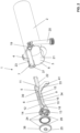
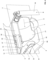
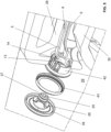
- FIGS. 1 to 3 show different views of an embodiment of a flushing arrangement 1 according to the invention.
- the Figure 1 shows the flushing arrangement 1 in the assembled state and the Figures 2 and 3 show corresponding exploded views.
- the flushing arrangement 1 comprises a flushing pipe 2 with a flushing water section 3 and a bidet water section 4, which is arranged fluidically separated from the flushing water section 3, and a water distributor 5 connected to the flushing pipe 2.
- the flushing pipe 2 can be used to supply flushing water S and bidet water B to the water distributor 5 separately from one another.
- the flushing pipe 5 can be supplied with flushing water via a flushing bend 42.
- the flushing bend is typically connected to a cistern.
- the flushing water section 3 has a flushing water outlet opening 6, via which flushing water S can be supplied to the water distributor 5.
- the bidet water section 4 has a bidet water outlet opening 7, via which bidet water B can be supplied to the water distributor 5.
- the water distributor 5 has guide surfaces 33, 34 with which the flushing water S, which is located in the area of the water distributor, can be guided.
- the guide surfaces 33, 34 thus serve for the guided introduction of the flushing water S into a toilet bowl 28.
- the water distributor 5 also has a bidet water line 8, which can be fluidically connected to the bidet water outlet opening 7 of the flush pipe 2, such that bidet water B can be fed from the bidet water outlet opening 7 to the bidet water line 8.
- the bidet water pipe 8 has an external Recess 9, which correspondingly reduces the radial expansion of the bidet water pipe 8 in the area of the recess 9.
- the recess in the bidet water pipe 8 increases the cross-section of the water distributor 5 in the area of the recess 9.
- the recess creates a cross-sectional change for the flushing water in the area of the guide surfaces 33, 34.
- the cross-sectional change is to be understood in such a way that the area below the recess 9 can be enlarged.
- the increase in the cross-sectional change also depends on the design of the toilet bowl 28 in the area in which the water distributor 5 is arranged.
- the recess 9 preferably extends over at least half of the bidet water pipe 8. In the embodiment shown, the recess extends over significantly more than half of the bidet water pipe 8.
- the cross-section of the bidet water pipe 8 is reduced in the area of the recess 9. This reduction is determined by the Figure 10 explained below.
- the bidet water pipe 8 in the water distributor 5 is enclosed on the circumference by side walls 10.
- the side wall 10 has an opening 11 at the top, which is tightly closed with respect to water by a cover 12.
- the side wall 10 has the indentation 9.
- the cover 12 is preferably connected to the side wall 10 by means of a liquid material.
- the cover 12 can be connected to the side wall 10 using ultrasonic welding.
- the opening 11 is advantageous because the water distributor 5 can be easily manufactured through the opening 11.
- the cover 12 is located directly opposite the recess 9 and extends over the entire cross-section of the recess 9 in a direction perpendicular to the central axis of the bidet water pipe 8 as seen through the opening 11.
- the water distributor 5 is formed in one piece with the guide surfaces 33, 34 and with the bidet water pipe 8 and is preferably made of a plastic.
- a toilet bowl 28 comprises a Bowl space 29 and a receiving space 30 in which the flushing arrangement 1 is arranged.
- the toilet bowl 28 comprises a flushing water opening 31 facing the bowl space 29 and a bidet water opening 32.
- the flushing pipe 2 protrudes from the rear into the receiving space 30 and the water distributor 5 is located in the receiving space such that the guide surfaces 33, 34 are directed towards the flushing water opening 31 and that the bidet water line 28 leads to the bidet water opening 32.
- the guide surfaces 33, 34 ensure optimal introduction of the flushing water S into the bowl space 29 so that as entire a surface of the bowl space 29 as possible is wetted with the flushing water S.
- the bidet water line 8 also opens into the bowl space 29. A user can operate the bidet water line 8 independently of the flush and start a washing process.
- the Figures 1 , 2 and 3 further show the design of the flush pipe 2.
- the bidet water section 4 also has a bidet water inlet opening 19, via which a bidet water hose 20 can be connected.
- the bidet water inlet opening 19 is located to the side and across the flush pipe 2.
- the bidet water hose 20 can also be connected to the bidet water inlet opening 19 from the side, i.e. across the center axis of the flush pipe 2.
- the bidet water hose 20 is in fluidically tight contact with the bidet water inlet opening 19 via a plug connection.
- a cylindrical extension is also arranged, on which a spirit level is provided for aligning the flush pipe 2.
- the plug connection can be secured accordingly with a safety element 35.
- the bidet water section 4 is then diverted by 90° to 100° and is finally led to the bidet water outlet opening 7.
- the bidet water outlet opening 7 is then in fluidically tight contact with the bidet water line 8 of the water distributor 5.
- the bidet water section 4 is located eccentrically to the flush pipe 2 in the interior 21 of the flush pipe 2.
- the bidet water section 4 is preferably located above the flush water section 5 when viewed in the installed position.
- the bidet water section 4 and the flush water section 3 are fluidically separated from one another so that mixing of bidet water and flush water can be avoided.
- the cross-section of the flush water section 3 is considerably larger than the cross-section of the bidet water section 4.
- the flush water section 3 is larger in cross-section by a factor of 15 to 30 than the cross-section of the bidet water section 4. Other factors, in particular smaller or larger ones, are also conceivable.
- the Figures 1 to 4 further show that the bidet water pipe 8 has a first plug section 22 and the bidet water section 4 has a second plug section 23.
- the plug section 23 in the bidet water section 4 is designed as a "socket" and the plug section 22 of the bidet water pipe 8 is designed as a "plug".
- the two plug sections 22, 23 can be plugged together, i.e. the bidet water pipe 8 extends into the bidet water section 4 in the present case.
- the plug connection also includes a sealing element 36 so that the connection between the bidet water pipe 8 and the bidet water section 4 is watertight.
- a conical inlet section 37 is arranged in the area of the second plug-in section 23 of the bidet water section 4.
- the inlet section 37 has the advantage that the plug-in process is easier.
- the water distributor 5 is placed in the receiving space 30 of the toilet bowl 28 and then the toilet bowl 28 is pushed against the already permanently installed flush pipe 2.
- the conical inlet section 37 ensures that the first plug-in section 22 slides easily into the second plug-in section 23.
- the bidet water pipe 8 has a nozzle head 24, which is in the Figure 5 is shown in detail.
- the nozzle head 24 has an outlet nozzle 25.
- Bidet water B can be discharged in the direction of the bowl space 29 via the outlet nozzle 25 if required.
- the outlet nozzle 25 is preferably arranged in the nozzle head 24 so that it can be aligned. This means that the outlet nozzle 25 can be moved accordingly in the nozzle head 24 so that the direction of the jet of bidet water B can be adjusted.
- the water distributor 5 further has a bearing surface 42 with which the water distributor 5 is mounted in the bidet water opening 32.
- the nozzle head 24 is connected to the bidet water line 8 via a bayonet lock 26. This enables easy installation.
- the nozzle head 24 is arranged in relation to the bidet water opening 32 in the toilet bowl 28 in the area of the bowl space 29.
- the nozzle head is therefore arranged accordingly after the water distributor 5 has been installed in the receiving space 30.
- the nozzle head also has a flange surface 38, which comes to rest on the surface of the toilet bowl 28 in the area of the bidet water opening 32.
- the nozzle head also has a driving structure 27 for a tool on the inside. In the embodiment shown, the driving structure 27 is a hexagon socket.
- the water distributor 5 comprises the bidet water line 8 and the guide surfaces 33, 34 for the guided passage of the flushing water.
- the guide surfaces 33, 34 form three channel sections 15, 16, 17.
- the flushing water S is guided accordingly in these channel sections 15, 16, 17.
- the channel sections 15, 16, 17 are arranged opposite, in the installation position below, the bidet water line 8 and, when viewed in the installation position, protrude essentially downwards from the bidet water line 5.
- the channel sections 15, 16, 17 are essentially open when viewed downwards from the bidet water line 5 in the installation position.
- This open design has the advantage that the water distributor 5 can be used for a large number of different receiving spaces 30 in different toilet bowls 28.
- two guide surfaces 33, 34 are provided, these guide surfaces provide a middle channel section 15, a right channel section 16 and a left channel section 17. Accordingly, three channel sections 15, 16, 17 are formed, which are positioned in such a way that they optimally introduce the flushing water into the toilet bowl 28.
- the right channel section 16 and the left channel section 17 ensure that the bowl space 29 of the toilet bowl 28 is wetted with flushing water essentially on the circumference, while the middle channel section provides a flushing jet into the water area of the siphon of the toilet bowl 28 for a corresponding flushing effect.
- the bidet water pipe 8 runs essentially in the middle channel section 15 and the indentation 9 also faces the middle channel section 15.
- the indentation 9 thus has the advantage that the cross-section of the middle channel section 15 can be enlarged so that the flushing water flowing in the middle channel section is subject to less flow resistance.
- the right channel section 16 and the left channel section 17 extend laterally to the bidet water pipe 8 when viewed in the installation position and are located essentially below the bidet water pipe 8.
- the middle channel section 17 has a deflection surface 18 on the front, which deflects the flushing water S downwards in the middle channel section 17 when viewed in the installed position.
- the right channel section 16 and the left channel section 17 also each have a deflection surface 18 on the front, which deflect the flushing water laterally to the middle channel section.
- the cross-section of the bidet water pipe 8 is shown.
- the bidet water pipe 8 extends in the area of the first plug-in section 22 as a cylindrical opening with a constant cross-section.
- the cross-section of the bidet water pipe 8 is continuously reduced until the minimum diameter of the recess is reached.
- the cross-section of the bidet water pipe 8 then changes back to a larger size and again reaches a maximum cross-section in the area of the end of the recess 9.
- the bidet water pipe 8 comprises a deflection section 14 at its front end 13, i.e. after the indentation as seen in the direction of flow.
- the deflection section 14 With the deflection section 14, the bidet water B is deflected upwards in the installed position by an angle ⁇ of 5 to 15°, in particular from 8° to 12°.
- This means that the deflection section 14 is essentially at an angle of 5 to 15°, in particular from 8° to 12°, to the central axis of the bidet water pipe 8.
- the transitions in the cross sections are designed as ramps inclined at an angle. These ramps achieve a flow regime that is less susceptible to losses.
- an injection point 39 is shown.
- the water distributor 5 can be injected into the injection mold via this injection point 39.
- the injection point 39 is essentially located in the middle of the bidet water pipe 8. However, the injection point 39 only disturbs the water flow in the bidet water pipe 8 insignificantly.
- the flush pipe 2 is mounted in a stationary manner, the water distributor 5 is placed in the receiving space 30, and the toilet bowl 28 is moved along a longitudinal movement onto the stationary flush pipe 2, during which movement the bidet water line 8 of the water distributor 5 is connected to the bidet water section of the flush pipe 2.
- flushing arrangement bayonet lock 2 flush pipe 27 take-home structure 3 rinse water section 28 toilet bowl 4 bidet water section 29 bowl space 5 water distributor 30 recording room 6 flush water outlet opening 31 flush water opening 7 bidet water outlet 32 bidet water opening 8 bidet water pipe 33 guide surface 9 indentation 34 guide surface 10 side wall 35 securing element 11 opening 36 sealing element 12 Lid 37 inlet section 13 front end 38 flange surface 14 deflection section 39 injection point 15 middle section of the canal 40 areas 16 right canal section 41 bridge section 17 left canal section 42 storage area 18 deflection surface 43 seal 19 bidet water inlet 44 back wall 20 bidet water hose B bidet water 21 interior S rinse water 22 first plug-in section ⁇ angle 23 second plug-in section 24 nozzle head 25 outlet nozzle
Landscapes
- Health & Medical Sciences (AREA)
- Public Health (AREA)
- Life Sciences & Earth Sciences (AREA)
- Engineering & Computer Science (AREA)
- Hydrology & Water Resources (AREA)
- Water Supply & Treatment (AREA)
- Molecular Biology (AREA)
- Epidemiology (AREA)
- Bidet-Like Cleaning Device And Other Flush Toilet Accessories (AREA)
Description
- Die vorliegende Erfindung betrifft eine Spülanordnung mit einem Spülrohr und einem Wasserverteiler nach Anspruch 1.
- Aus dem Stand der Technik sind Anschlusselemente für Toiletten bekannt geworden, über welche einer Toilette Spülwasser zugeführt werden kann und welche gleichzeitig eine Bidetfunktion aufweisen.
- Beispielsweise offenbart die
DE 10 2018 127 235 ein solches Anschlusselement. Aus derDE 10 2018 127 235 ist ein Anschlusselement für eine Sanitäranordnung bekannt geworden. Das Anschlusselement umfasst ein Rohrelement mit einer Anschlussschnittstelle, an welche ein Bidetelement anschliessbar ist, und mit einem Hauptkanal zur Zuführung von Spülwasser in eine Toilettenschüssel. - Aus der
WO 2016/105294 ist eine Spülvorrichtung bekannt geworden, welche ebenfalls eine Spül- und eine Bidetfunktion aufweist. Allerdings ist die Spülvorrichtung gemäss derWO 2016/105294 strömungstechnisch ungünstig ausgebildet, wodurch die Oberfläche der Toilettenschüssel nur ungenügend überströmt wird. Ein weiterer Nachteil ergeht von der sehr komplexen Art der Montage der Spülvorrichtung, welche zeitraubend und fehleranfällig ist. Gerade das Einschrauben der Düse in die im Spülrohr liegende Düsenaufnahmen hat sich als aufwändig und nachteilig herausgestellt. - Ausgehend von diesem Stand der Technik liegt der Erfindung eine Aufgabe zugrunde, eine Spülanordnung mit Bidetfunktion anzugeben, welche die Nachteile des Standes der Technik überwindet. Insbesondere ist es eine Aufgabe der vorliegenden Erfindung, eine Spülanordnung anzugeben, welche einfacher und dennoch prozesssicher montierbar ist. Diese Aufgabe löst die Spülanordnung nach Anspruch 1. Demgemäss umfasst eine Spülanordnung ein Spülrohr mit einem Spülwasserabschnitt und einem Bidetwasserabschnitt, der vom Spülwasserabschnitt getrennt angeordnet ist, und ein sich dem Spülrohr anschliessenden Wasserverteiler. Der Spülwasserabschnitt weist eine Spülwasseraustrittsöffnung auf, über welche Spülwasser dem Wasserverteiler zuführbar ist, und der Bidetwasserabschnitt weist eine Bidetwasseraustrittsöffnung auf, über welche Bidetwasser dem Wasserverteiler zuführbar ist. Der Wasserverteiler weist weiter Leitflächen zur geführten Einleitung des Spülwassers in eine Toilettenschüssel und eine Bidetwasserleitung auf. Die Bidetwasserleitung ist von den Leitflächen getrennt angeordnet. Spülwasser ist aus der Spülwasseraustrittsöffnung des Spülrohrs den Leitflächen zuführbar und Bidetwasser ist aus der Bidetwasseraustrittsöffnung des Bidetwasserabschnitts der Bidetwasserleitung zuführbar. Weiter verfügt die Bidetwasserleitung über einen ersten Steckabschnitt und der Bidetwasserabschnitt verfügt über einen zweiten Steckabschnitt, wobei die Steckabschnitte derart ausgebildet sind, dass die Bidetwasserleitung über die Steckabschnitte mit dem Bidetwasserabschnitt verbindbar ist.
- Durch die Anordnung der beiden Steckabschnitte ergeht der Vorteil, dass die Bidetwasserleitung sehr einfach entlang einer Steckverbindung miteinander verbunden werden kann.
- Bei einer bevorzugten Montageart ist der Wasserverteiler in einer Toilettenschüssel vormontiert und das Spülrohr liegt ortsfest an einer Montagestruktur, wie einem Montagerahmen. Durch die beiden Steckabschnitte ergeht der Vorteil, dass die Toilettenschüssel in herkömmlicher Art in Richtung Spülrohr geschoben werden kann, wobei bei der Bewegung die beiden Steckabschnitte miteinander zusammengesteckt werden.
- Vorzugsweise sind der erste Steckabschnitt und der zweite Steckabschnitt derart ausgebildet, dass die beiden Steckabschnitte entlang einer geradlinigen Längsbewegung miteinander verbindbar sind. Besonders bevorzugt sind der erste Steckabschnitt und der zweite Steckabschnitt derart ausgebildet, dass die beiden Steckabschnitte ausschliesslich entlang einer geradlinigen Längsbewegung miteinander verbindbar sind.
- Unter der Ausdrucksweise " ausschliesslich entlang einer geradlinigen Längsbewegung" wird verstanden, dass die Steckbewegung nur eine Längsbewegung entlang einer geradlinigen Achse ausführt, nicht aber eine Dreh- oder Rotationsbewegung um die Achse. Die Achse ist vorzugweise die Mittelachse des Bidetwasserabschnitts bzw. der Bidetwasserleitung. Das heisst, die Steckbewegung wird entlang der Mittelachse ausgeführt.
- Die Steckverbindung ist bezüglich Wasser dicht ausgebildet, derart, dass kein Bidetwasser in das Spülwasser und kein Spülwasser in das Bidetwasser fliessen kann. Vorzugsweise ist zwischen den beiden Steckabschnitten ein O-Ring angeordnet.
- Vorzugsweise ist die Verbindung über die beiden Steckabschnitte die einzige mechanische Verbindung zwischen dem Wasserverteiler und dem Spülrohr. Das heisst, dass der Wasserverteiler vorzugsweise ausschliesslich über die besagte Steckverbindung mit dem Spülrohr in Verbindung steht.
- Einer der Steckabschnitte ragt vorzugsweise in den anderen der Steckabschnitte ein, wobei zwischen den Steckabschnitten weiter ein Dichtungselement angeordnet ist.
- Vorzugsweise weist die Bidetwasseraustrittsöffnung einen Führungsabschnitt auf, welcher sich um die Bidetwasseraustrittsöffnung herum erstreckt. Der Führungsabschnitt ist vorzugsweise konisch auf den Durchmesser der Bidetwasseraustrittsöffnung zulaufend ausgebildet und stellt eine Führung für den Steckabschnitt bereit.
- Besonders bevorzugt ist einer der Steckabschnitte als "Buchse" und der andere der Steckabschnitte ist als "Stecker" ausgebildet. Die Buchse weist dabei einen vorzugsweise kreiszylindrischen Innenraum auf, in welcher der Stecker, der aussenseitig ebenfalls kreiszylindrisch ausgebildet ist, einschiebbar ist. Zwischen den beiden Zylinderflächen liegt das Dichtelement.
- Die Bidetwasserleitung weist vorzugsweise eine aussenseitig zur Bidetwasserleitung liegende Einbuchtung auf, welche die radiale Ausdehnung der Bidetwasserleitung im Bereich der Einbuchtung verkleinert. Die Einbuchtung verkleinert die radiale Ausdehnung zu den Leitflächen hin.
- Durch die Einbuchtung wird ein vergrösserter Raumbereich für das Spülwasser geschaffen. Mit anderen Worten wird durch die Einbuchtung in der Bidetwasserleitung der Querschnitt für das Spülwasser im Bereich der Einbuchtung vergrössert. Hierdurch kann der Durchfluss von Spülwasser beim Durchfliessen des Wasserverteilers verbessert werden. Es kann demnach eine Spülanordnung mit Bidetfunktion angegeben werden, welche verbesserte strömungstechnische Eigenschaften aufweist.
- Die Einbuchtung bewirkt im Bereich der Einbuchtung vorzugweise eine Querschnittsverengung in der Bidetwasserleitung. Da der Wasserstrahl der Bidetfunktion im Vergleich zum Wasserstrahl des Spülwassers mit geringerer Genauigkeit abgegeben werden kann, weist eine Querschnittsverengung der Bidetwasserleitung keinen negativen Effekt auf den Wasserstrahl für die Bidetfunktion auf.
- Die Einbuchtung bzw. die Querschnittsverengung ist vorzugsweise derart ausgebildet, dass der Querschnitt der Leitflächen im Bereich der Querschnittsverengung grösser wird.
- Unter der Ausdrucksweise "radiale Ausdehnung" wird die Ausdehnung der Bidetwasserleitung quer zur Mittelachse der Bidetwasserleitung verstanden. Die Einbuchtung ist vorzugsweise derart, dass sich die Einbuchtung in eine Richtung, nämlich von unten her, radial in die Bidetwasserleitung hineinerstreckt.
- Die Einbuchtung erstreckt sich von aussen her in die Bidetwasserleitung und verkleinert deren Aussenmass.
- Vorzugsweise ist das Spülrohr separat vom Wasserverteiler ausgebildet. Es sind zwei unterschiedliche Elemente, welche in einen entsprechenden Aufnahmeraum in einer Toilettenschüssel eingesetzt werden können.
- Die Bidetwasserleitung im Wasserverteiler und der Bidetwasserabschnitt im Spülrohr sind fluidisch vom Spülwasser getrennt. Das heisst, Spülwasser und Bidetwasser werden separat zueinander geführt und es kann zu keiner Vermischung kommen.
- Vorzugsweise erstreckt sich die Einbuchtung über mindestens die Hälfte der Länge der Bidetwasserleitung. Hierdurch wird sichergestellt, dass die Spülanordnung in vielen unterschiedlich ausgebildeten Toilettenschüsseln eingesetzt werden kann.
- Wie oben erläutert kann sich der Querschnitt der Bidetwasserleitung im Bereich der Einbuchtung verkleinern. In den Bereichen vor und nach der Einbuchtung vergrössert sich der Querschnitt der Bidetwasserleitung im Vergleich zum verkleinerten Querschnitt im Bereich der Einbuchtung. Die Querschnittsverkleinerung auf den verkleinerten Querschnitt bzw. die Querschnittsvergrösserung vom verkleinerten Querschnitt erfolgt vorzugsweise stetig.
- Vorzugsweise ist die Bidetwasserleitung im Wasserverteiler umfangsseitig durch Seitenwände umschlossen, wobei eine Seitenwand eine Öffnung aufweist, welche durch einen Deckel bezüglich Wasser dicht verschlossen ist. Durch die Anordnung des Deckels in der Öffnung ergeht der Vorteil, dass der Wasserverteiler mittels eines Spritzgiessverfahrens einfach hergestellt werden kann.
- Der Deckel ist vorzugsweise stoffschlüssig mit dem Wasserverteiler verbunden. Eine stoffschlüssige Verbindung kann durch eine Klebestelle und/oder eine Ultraschallschweissung erreicht werden.
- Besonders bevorzugt liegt der Deckel gegenüber der Einbuchtung. Besonders bevorzugt erstreckt sich der Deckel mindestens über die gleiche Länge wie die Einbuchtung. Hierdurch kann die Einbuchtung werkzeugtechnisch besonders einfach geformt werden.
- Die Leitflächen sowie die Bidetwasserleitung sind einstückig ausgebildet.
- Vorzugsweise weist die Bidetwasserleitung an ihrem vorderen Ende einen Umlenkabschnitt auf, welcher das Bidetwasser in Einbaulage um einen Winkel von 5° bis 15°, insbesondere von 8° bis 12°, nach oben hin umlenkt.
- Vorzugsweise bilden die Leitflächen Kanalabschnitte für das Spülwasser, wobei die Kanalabschnitte gegenüber der Bidetwasserleitung in Einbaulage nach unten hin gesehen im Wesentlichen offen sind.
- Die Begrenzung der Kanalabschnitte nach unten hin wird durch die Aufnahmeöffnung in der Toilettenschüssel bereitgestellt. Durch die in Einbaulage nach unten hin offene Gestaltung der Kanalabschnitte ergeht der Vorteil, dass die Spülanordnung in vielen unterschiedlich ausgebildeten Toilettenschüsseln eingesetzt werden kann.
- Vorzugsweise sind mindestens zwei Leitflächen vorgesehenen, die einen mittleren Kanalabschnitt, einen rechten Kanalabschnitt, der rechts zum mittleren Kanalabschnitt liegt, und einen linken Kanalabschnitt, der links zum mittleren Kanalabschnitt liegt, bereitstellen.
- Vorzugsweise verläuft die Bidetwasserleitung im mittleren Kanalabschnitt und wobei die Einbuchtung dem mittleren Kanalabschnitt zugewandt ist.
- Typischerweise muss der mittlere Spülstrahl mit einer geringeren Genauigkeit als der rechte bzw. der linke Spülstrahl in die Toilettenschüssel geführt werden. Die Anordnung der Bidetwasserleitung im mittleren Kanalabschnitt hat somit den Vorteil, dass der linke bzw. der rechte Spülstrahl durch die Bidetwasserleitung unbeeinflusst bleiben. Es wird demnach ausschliesslich der mittlere Spülstrahl durch die Anordnung der Bidetwasserleitung beeinflusst.
- Vorzugsweise erstrecken sich der rechte Kanalabschnitt und der linke Kanalabschnitt in Einbaulage gesehen seitlich zur Bidetwasserleitung und unterhalb zur Bidetwasserleitung.
- Mit anderen Worten gesagt liegt die Bidetwasserleitung zwischen dem rechten Kanalabschnitt und dem linken Kanalabschnitt und oberhalb des mittleren Kanalabschnittes.
- Vorzugsweise weist der mittlere Kanalabschnitt frontseitig eine Umlenkfläche auf, welche das Spülwasser im mittleren Kanalabschnitt in Einbaulage nach unten hin umlenkt.
- Vorzugsweise weist der rechte Kanalabschnitt und der linke Kanalabschnitt frontseitig eine Umlenkfläche auf, welche das Spülwasser seitlich zum mittleren Kanalabschnitt umlenken.
- Vorzugsweise weist der Bidetwasserabschnitt eine Bidetwassereintrittsöffnung auf, über welche ein Bidetwasserschlauch anschliessbar ist, wobei die Bidetwassereintrittsöffnung vorzugsweise seitlich zum Spülrohr liegt.
- Vorzugsweise liegt der Bidetwasserabschnitt exzentrisch zum Spülrohr im Innenraum des Spülrohrs, wobei der Bidetwasserabschnitt in Einbaulage gesehen vorzugsweise oberhalb des Spülwasserabschnitts liegt.
- Vorzugsweise ist der Querschnitt des Spülwasserabschnitts um einen Faktor 3 bis 10 grösserals der Querschnitt des Bidetwasserabschnitts.
- Vorzugsweise schliesst sich der Bidetwasserleitung ein Düsenkopf mit einer Austrittsdüse an, wobei die Austrittsdüse im Düsenkopf vorzugsweise ausrichtbar angeordnet ist. Die Richtung des Bidetstrahls wird durch die Ausrichtung des Düsenkopfs bestimmt, welche durch den Benutzer eingestellt werden kann.
- Vorzugsweise steht der Düsenkopf über einen Bajonettverschluss mit der Bidetwasserleitung in Verbindung.
- Vorzugsweise weist der Düsenkopf innenseitig eine Mitnahmestruktur für ein Werkzeug, insbesondere einen Innensechskant, auf.
- Eine Anordnung umfasst eine Spülanordnung nach obiger Beschreibung und eine Toilettenschüssel mit einem Schüsselraum und einem Aufnahmeraum, dem sich eine dem Schüsselraum zugewandete Spülwasseröffnung und eine Bidetwasseröffnung anschliessen. Der Aufnahmeraum mündet somit über die Spülwasseröffnung und die Bidetwasseröffnung in den Schüsselraum. Das Spülrohr ragt in den Aufnahmeraum ein und der Wasserverteiler liegt derart im Aufnahmeraum, dass die Leitflächen zur Spülwasseröffnung gerichtet sind und dass die Bidetwasserleitung zur Bidetwasseröffnung führt.
- Vorzugsweise weist die Toilettenschüssel eine in einer Ebene liegende Rückwand auf, mit welcher die Toilettenschüssel an eine Gebäudewand montierbar ist, wobei die Bidetwasserleitung eine Bidetwassereintrittsöffnung zur Verbindung mit einem Bidetwasserschlauch aufweist, welche Bidetwassereintrittsöffnung in einem Abstand von maximal 10 Zentimeter, insbesondere maximal 5 Zentimeter von der Rückwand (44) entfernt ist.
- Der Abstand definiert sich als Abstand rechtwinklig auf die besagte Rückwand bzw. Ebene gesehen.
- Durch diese Anordnung kommt die Bidetwasseröffnung sehr nahe an die Gebäudewand zu liegen und liegt von der Gebäudewand gesehen nicht tief im Inneren der Toilettenschüssel, was den Vorteil hat, dass ein Bidetwasserschlauch als vergleichsweise kurzes Schlauchstück ausgebildet werden kann. Hierdurch stellt der Bidetwasserschlauch bei der Montage der Toilettenschüssel kein Hindernis dar.
- Die Bidetwasseröffnung liegt in Einbaulage oberhalb der Spülwasseröffnung. Typischerweise ist die Spülwasseröffnung durch einen Randbereich der Toilettenschüssel verdeckt, wobei die Bidetwasseröffnung vorzugsweise in diesem Randbereich liegt.
- Vorzugsweise wird die Düse von Seiten des Schüsselraums mit dem Wasserverteiler bzw. mit der Bidetwasserleitung verbunden.
- Durch die Anordnung der sepraraten Bidetwasseröffnung in der Toilettenschüssel ergeht der Vorteil, dass dem Benutzer auf einen Blick die Bidetfunktion klar ist.
- Ein Verfahren zur Montage einer Anordnung gemäss obiger Beschreibung ist dadurch charakterisiert, dass
- das Spülrohr ortsfest montiert wird,
- der Wasserverteiler im Aufnahmeraum der Toilettenschüssel platziert wird, und
- dass die Toilettenschüssel entlang einer Längsbewegung auf das ortsfest montierte Spülrohr bewegt wird, wobei während dieser Bewegung die Bidetwasserleitung des Wasserverteilers mit dem Bidetwasserabschnitt des Spülrohrs über die Steckabschnitte verbunden wird.
- Weitere Ausführungsformen sind in den abhängigen Ansprüchen angegeben.
- Bevorzugte Ausführungsformen der Erfindung werden im Folgenden anhand der Zeichnungen beschrieben, die lediglich zur Erläuterung dienen und nicht einschränkend auszulegen sind. In den Zeichnungen zeigen:
- Fig. 1
- eine perspektivische Schnittdarstellung einer Anordnung mit einer Spülanordnung gemäss einer bevorzugten Ausführungsform der vorliegenden Erfindung und einer Toilettenschüssel;
- Fig. 2
- eine erste Explosionsansicht der
Figur 1 ; - Fig. 3
- eine zweite Explosionsansicht der
Figur 1 ; - Fig. 4
- eine Schnittdarstellung eines Details der
Figur 1 ; - Fig. 5
- eine perspektivische Explosionsdarstellung der Frontpartie der Spülanordnung nach
Figur 1 ; - Fig. 6
- eine perspektivische Ansicht eines Wasserverteilers der Spülanordnung nach
Figur 1 von unten; - Fig. 7
- eine Frontansicht des Wasserverteilers von
Figur 6 ; - Fig. 8
- eine Rückansicht des Wasserverteilers von
Figur 6 ; - Fig. 9
- eine Seitenansicht des Wasserverteilers von
Figur 6 ; und - Fig. 10
- eine Schnittdarstellung des Wasserverteilers von
Figur 6 . - Die
Figuren 1 bis 3 zeigen verschiedene Ansichten einer Ausführungsform einer erfindungsgemässen Spülanordnung 1. DieFigur 1 zeigt die Spülanordnung 1 im montierten Zustand und dieFiguren 2 und3 zeigen entsprechende Explosionsdarstellungen. - Die Spülanordnung 1 umfasst ein Spülrohr 2 mit einem Spülwasserabschnitt 3 und einem Bidetwasserabschnitt 4, der vom Spülwasserabschnitt 3 fluidisch getrennt angeordnet ist, und ein sich dem Spülrohr 2 anschliessenden Wasserverteiler 5. Mit dem Spülrohr 2 kann dem Wasserverteiler 5 Spülwasser S und Bidetwasser B getrennt voneinander zugeführt werden. Das Spülrohr 5 über einen Spülbogen 42 mit Spülwasser versorgbar. Der Spülbogen steht typischerweise mit einem Spülkasten in Verbindung.
- Der Spülwasserabschnitt 3 weist eine Spülwasseraustrittsöffnung 6 auf, über welche Spülwasser S dem Wasserverteiler 5 zuführbar ist. Der Bidetwasserabschnitt 4 weist eine Bidetwasseraustrittsöffnung 7 auf, über welche Bidetwasser B dem Wasserverteiler 5 zugeführt werden kann.
- Der Wasserverteiler 5 weist Leitflächen 33, 34 auf, mit welchen das Spülwasser S, welches sich im Bereich des Wasserverteilers befindet, geleitet werden kann. Die Leitflächen 33, 34 dienen also zur geführten Einleitung des Spülwassers S in eine Toilettenschüssel 28. Weiter weist der Wasserverteiler 5 eine Bidetwasserleitung 8 auf, welche mit der Bidetwasseraustrittsöffnung 7 des Spülrohrs 2 fluidisch verbindbar ist, derart, dass Bidetwasser B aus der Bidetwasseraustrittsöffnung 7 der Bidetwasserleitung 8 zuführbar ist.
- Die Bidetwasserleitung 8 weist eine aussenseitig zur Bidetwasserleitung 8 liegende Einbuchtung 9 auf, welche die radiale Ausdehnung der Bidetwasserleitung 8 im Bereich der Einbuchtung 9 entsprechend verkleinert. Durch die Einbuchtung in der Bidetwasserleitung 8 vergrössert sich der Querschnitt des Wasserverteilers 5 im Bereich der Einbuchtung 9. Hierdurch erfährt das Spülwasser S geringer strömungstechnische Verluste und kann somit genauer der Toilettenschüssel 28 zugeführt werden. Durch die Einbuchtung entsteht im Bereich der Leitflächen 33, 34 eine Querschnittsveränderung für das Spülwasser. Die Querschnittsveränderung ist so zu verstehen, dass der Bereich unterhalb der Einbuchtung 9 vergrössert werden kann. Die Vergrösserung der Querschnittsveränderung ist aber auch abhängig von der Ausbildung der Toilettenschüssel 28, in dem Bereich, in welchem der Wasserverteiler 5 angeordnet ist.
- Die Einbuchtung 9 erstreckt sich vorzugsweise über mindestens die Hälfte der Bidetwasserleitung 8. In der gezeigten Ausführungsform erstreckt sich die Einbuchtung über deutlich mehr als die Hälfte der Bidetwasserleitung 8. Der Querschnitt der Bidetwasserleitung 8 wird im Bereich der Einbuchtung 9 verkleinert. Diese Verkleinerung wird anhand der
Figur 10 weiter unten erläutert. - Die Bidetwasserleitung 8 im Wasserverteiler 5 ist umfangsseitig durch Seitenwände 10 umschlossen. Die Seitenwand 10 weist in der gezeigten Ausführungsform nach oben hin eine Öffnung 11 auf, welche durch einen Deckel bezüglich Wasser 12 dicht verschlossen ist. Nach unten hin weist die Seitenwand 10 die Einbuchtung 9 auf. Der Deckel 12 ist bevorzugt stoffflüssig mit der Seitenwand 10 verbunden. Beispielsweise kann der Deckel 12 mit einer Ultraschallschweissung mit der Seitenwand 10 verbunden werden. Die Öffnung 11 ist vorteilhaft, weil der Wasserverteiler 5 durch die Öffnung 11 einfach hergestellt werden kann. Insbesondere ist es möglich, einen Kern einer Spitzgiessmaschine durch die Öffnung 10 in den Querschnitt der Bidetwasserleitung 8 einzuführen, sodass der untere Bereich der Bidetwasserleitung 8 mit der Einbuchtung 9 entsprechend einfach geformt werden kann. Der Deckel 12 liegt in der gezeigten Ausführungsform direkt gegenüber der Einbuchtung 9 und erstreckt sich über den gesamten Querschnitt der Einbuchtung 9 in rechtwinkliger Richtung zur Mittelachse der Bidetwasserleitung 8 durch die Öffnung 11 gesehen.
- Der Wasserverteiler 5 ist mit den Leitflächen 33, 34 sowie mit der Bidetwasserleitung 8 einstückig ausgebildet und ist vorzugsweise aus einem Kunststoff hergestellt.
- Von der
Figur 1 wird die konkrete Einbausituation der Spülanordnung 1 in einer Toilettenschüssel 28 gezeigt. Typischerweise umfasst eine Toilettenschüssel 28 einen Schüsselraum 29 und einen Aufnahmeraum 30, in welchem die Spülanordnung 1 angeordnet ist. In der gezeigten Ausführungsform umfasst die Toilettenschüssel 28 eine dem Schüsselraum 29 zugewandte Spülwasseröffnung 31 und eine Bidetwasseröffnung 32. Das Spülrohr 2 ragt von hinten her in den Aufnahmeraum 30 ein und der Wasserverteiler 5 liegt derart im Aufnahmeraum, dass die Leitflächen 33, 34 zur Spülwasseröffnung 31 gerichtet sind und dass die Bidetwasserleitung 28 zur Bidetwasseröffnung 32 führt. Die Leitflächen 33, 34 sorgen für eine optimale Einleitung des Spülwassers S in den Schüsselraum 29, so dass möglichst die gesamte Oberfläche des Schüsselraums 29 mit dem Spülwasser S benetzt wird. Die Bidetwasserleitung 8 mündet ebenfalls in den Schüsselraum 29. Ein Benutzer kann die Bidetwasserleitung 8 unabhängig von der Spülung betätigen und einen Waschvorgang starten. - Die
Figuren 1 ,2 und3 zeigen weiterhin die Ausbildung des Spülrohres 2. Der Bidetwasserabschnitt 4 weist weiterhin eine Bidetwassereintrittsöffnung 19 auf, über welche ein Bidetwasserschlauch 20 anschliessbar ist. Die Bidetwassereintrittsöffnung 19 liegt dabei seitlich und quer zum Spülrohr 2. Das heisst, der Bidetwasserschlauch 20 kann ebenfalls von der Seite, das heisst quer zur Mittelachse des Spülrohres 2, an die Bidetwassereintrittsöffnung 19 angeschlossen werden. Vorzugsweise ist der Bidetwasserschlauch 20 mit der Bidetwassereintrittsöffnung 19 über eine Steckverbindung in fluidisch dichtem Kontakt. Im Bereich der Bidetwassereintrittsöffnung 19 ist zudem ein zylindrischer Fortsatz angeordnet, auf welchem eine Wasserwaage zur Ausrichtung des Spülrohrs 2 vorgesehen ist. - Die Steckverbindung kann mit einem Sicherungselement 35 entsprechend gesichert werden. Weiter wird dann der Bidetwasserabschnitt 4 um 90° bis 100° umgelenkt und wird schliesslich zur Bidetwasseraustrittsöffnung 7 geführt. Die Bidetwasseraustrittsöffnung 7 steht dann in fluidisch dichtem Kontakt mit der Bidetwasserleitung 8 des Wasserverteilers 5. In der gezeigten Ausführungsform liegt der Bidetwasserabschnitt 4 exzentrisch zum Spülrohr 2 im Innenraum 21 des Spülrohres 2. Der Bidetwasserabschnitt 4 liegt in Einbaulage gesehen vorzugsweise oberhalb des Spülwasserabschnittes 5. Der Bidetwasserabschnitt 4 und der Spülwasserabschnitt 3 sind fluidisch getrennt voneinander, so dass eine Vermischung von Bidetwasser und Spülwasser vermieden werden kann. Der Querschnitt des Spülwasserabschnittes 3 ist um einiges grösser als der Querschnitt des Bidetwasserabschnittes 4. Vorzugsweise ist der Spülwasserabschnitt 3 im Querschnitt um einen Faktor 15 bis 30 grösser als der Querschnitt des Bidetwasserabschnittes 4. Andere Faktoren, insbesondere kleinere oder grössere, sind auch denkbar.
- Die
Figuren 1 bis 4 zeigen weiterhin, dass die Bidetwasserleitung 8 über einen ersten Steckabschnitt 22 und der Bidetwasserabschnitt 4 über einen zweiten Steckabschnitt 23 verfügen. Der Steckabschnitt 23 im Bidetwasserabschnitt 4 ist hier als "Buchse" und der Steckabschnitt 22 der Bidetwasserleitung 8 ist hier als "Stecker" ausgebildet. Die beiden Steckabschnitte 22, 23 können miteinander zusammengesteckt werden, das heisst, die Bidetwasserleitung 8 ragt im vorliegenden Fall in den Bidetwasserabschnitt 4 ein. Die Steckverbindung umfasst weiterhin ein Dichtungselement 36, so dass die Verbindung zwischen der Bidetwasserleitung 8 und dem Bidetwasserabschnitt 4 bezüglich Wasser dicht ist. - Weiter ist in der gezeigten Ausführungsform im Bereich des zweiten Steckabschnittes 23 des Bidetwasserabschnittes 4 eine konische Einlaufstrecke 37 angeordnet. Die Einlaufstrecke 37 hat den Vorteil, dass der Steckvorgang sich einfacher gestaltet. Typischerweise wird der Wasserverteiler 5 im Aufnahmeraum 30 der Toilettenschüssel 28 platziert und dann wird die Toilettenschüssel 28 gegen das bereits fest installierte Spülrohr 2 verschoben. Durch die konische Einlaufstrecke 37 wird sichergestellt, dass ein gutes Eingleiten des ersten Steckabschnittes 22 in den zweiten Steckabschnitt 23 ermöglicht wird.
- Frontseitig weist die Bidetwasserleitung 8 einen Düsenkopf 24 auf, welcher in der
Figur 5 im Detail dargestellt ist. Der Düsenkopf 24 weist eine Austrittsdüse 25 auf. Über die Austrittsdüse 25 kann Bidetwasser B bei Bedarf in Richtung des Schüsselraums 29 abgegeben werden. Die Austrittsdüse 25 ist im Düsenkopf 24 vorzugsweise ausrichtbar angeordnet. Das heisst, die Austrittsdüse 25 kann im Düsenkopf 24 entsprechend verschoben werden, so dass die Richtung des Strahls des Bidetwassers B eingestellt werden kann. In der vorliegenden Ausführungsform weist der Wasserverteiler 5 weiter eine Lagerfläche 42 auf, mit welcher der Wasserverteiler 5 in der Bidetwasseröffnung 32 gelagert ist. - In der gezeigten Ausführungsform ist der Düsenkopf 24 über einen Bajonettverschluss 26 mit der Bidetwasserleitung 8 in Verbindung. Dies ermöglicht eine einfache Montage. Der Düsenkopf 24 ist bezüglich der Bidetwasseröffnung 32 in der Toilettenschüssel 28 im Bereich des Schüsselraumes 29 angeordnet. Der Düsenkopf wird demnach nach der Montage des Wasserverteilers 5 im Aufnahmeraum 30 entsprechend angeordnet. Weiter weist der Düsenkopf eine Flanschfläche 38 auf, welche auf die Oberfläche der Toilettenschüssel 28 im Bereich der Bidetwasseröffnung 32 zu liegen kommt. Der Düsenkopf weist innenseitig weiterhin eine Mitnahmestruktur 27 für ein Werkzeug auf. In der gezeigten Ausführungsform ist die Mitnahmestruktur 27 ein Innensechskant. Ein Werkzeug kann dabei in den Innensechskant eingreifen, so dass der Düsenkopf im Rahmen seiner Verschwenkbarkeit im Bajonettverschluss 26 entsprechend verschwenkt werden kann. Weiter ist im Bereich der Flanschfläche 38 eine Dichtung 43 angeordnet. Anhand der
Figuren 6 bis 10 wird nun der Wasserverteiler 5 genauer beschrieben. Wie bereits erwähnt umfasst der Wasserverteiler 5 die Bidetwasserleitung 8 und die Leitflächen 33, 34 für die geführte Durchleitung des Spülwassers. Die Leitflächen 33, 34 bilden in der gezeigten Ausführungsform drei Kanalabschnitte 15, 16, 17. In diesen Kanalabschnitten 15, 16, 17 wird das Spülwasser S entsprechend geführt. Die Kanalabschnitte 15, 16, 17 sind dabei gegenüber, in Einbaulage unterhalb, der Bidetwasserleitung 8 angeordnet und ragen in Einbaulage von der Bidetwasserleitung 5 her gesehen im Wesentlichen nach unten weg. Weiter sind die Kanalabschnitte 15, 16, 17 gegenüber der Bidetwasserleitung 5 in Einbaulage nach unten hin gesehen im Wesentlichen offen ausgebildet. Diese offene Ausbildung hat den Vorteil, dass der Wasserverteiler 5 für eine Vielzahl von verschiedenen Aufnahmeräumen 30 in verschiedenen Toilettenschüsseln 28 eingesetzt werden kann. In der gezeigten Ausführungsform sind zwei Leitflächen 33, 34 vorgesehen, diese Leitflächen stellen einen mittleren Kanalabschnitt 15, einen rechten Kanalabschnitt 16 und einen linken Kanalabschnitt 17 bereit. Es werden demnach drei Kanalabschnitte 15, 16, 17 gebildet, welche derart liegen, dass diese das Spülwasser optimal in die Toilettenschüssel 28 einbringen. Der rechte Kanalabschnitt 16 und der linke Kanalabschnitt 17 sorgen dafür, dass der Schüsselraum 29 der Toilettenschüssel 28 im Wesentlichen umfangsseitig mit Spülwasser benetzt wird, während der mittlere Kanalabschnitt einen Spülstrahl in den Wasserbereich des Siphons der Toilettenschüssel 28 für eine entsprechende Spülwirkung bereitstellt. - Von den
Figuren 6 bis 8 kann gut erkannt werden, dass die Bidetwasserleitung 8 im Wesentlichen im mittleren Kanalabschnitt 15 verläuft und die Einbuchtung 9 ist ebenfalls dem mittleren Kanalabschnitt 15 zugewandt. Die Einbuchtung 9 hat somit den Vorteil, dass der Querschnitt des mittleren Kanalabschnittes 15 vergrössert werden kann, so dass dem im mittleren Kanalabschnitt fliessenden Spülwasser ein geringerer Strömungswiderstand entgegen gesetzt wird. - Der rechte Kanalabschnitt 16 und der linke Kanalabschnitt 17 erstrecken sich in Einbaulage gesehen seitlich zur Bidetwasserleitung 8 und liegen im Wesentlichen unterhalb der Bidetwasserleitung 8.
- Weiter weist der mittlere Kanalabschnitt 17 frontseitig eine Umlenkfläche 18 auf, welche das Spülwasser S im mittleren Kanalabschnitt 17 in Einbaulage gesehen nach unten hin umlenkt. Der rechte Kanalabschnitt 16 und auch der linke Kanalabschnitt 17 weisen frontseitig ebenfalls je eine Umlenkfläche 18 auf, welche das Spülwasser seitlich zum mittleren Kanalabschnitt umlenken.
- In der
Figur 10 wird der Querschnitt der Bidetwasserleitung 8 gezeigt. Die Bidetwasserleitung 8 erstreckt sich im Bereich des ersten Steckabschnittes 22 als zylindrische Öffnung mit konstantem Querschnitt. Im Bereich der Einbuchtung 9 wird der Querschnitt des Bidetwasserleitung 8 kontinuierlich verkleinert bis der minimale Durchmesser der Einbuchtung erreicht wird. Anschliessend geht der Querschnitt der Bidetwasserleitung 8 wieder auf ein grösseres Mass über und erreicht erneut einen maximalen Querschnitt im Bereich des Endes der Einbuchtung 9. - Weiter umfasst die Bidetwasserleitung 8 an ihrem vorderen Ende 13, das heisst in Fliessrichtung gesehen nach der Einbuchtung, einen Umlenkabschnitt 14 auf. Mit dem Umlenkabschnitt 14 wird das Bidetwasser B in Einbaulage um einen Winkel α um 5 bis 15°, insbesondere von 8° bis 12°, nach oben hin umgelenkt. Das heisst, der Umlenkabschnitt 14 steht im Wesentlichen in einem Winkel von 5 bis 15°, insbesondere von 8° bis 12°, zur Mittelachse der Bidetwasserleitung 8. Die Übergänge in den Querschnitten sind als winklig geneigte Rampen ausgebildet. Durch diese Rampen wird ein Strömungsregime erreicht, welches bezüglich Verlusten weniger anfällig ist.
- Weiter wird in der
Figur 10 eine Anspritzstelle 39 gezeigt. Über diese Anspritzstelle 39 kann der Wasserverteiler 5 entsprechend in die Spritzgiessform eingespritzt werden. Die Anspritzstelle 39 steht hier im Wesentlichen mittig in der Bidetwasserleitung 8. Die Anspritzstelle 39 stört aber den Wasserfluss in der Bidetwasserleitung 8 nur unwesentlich. - Von den
Figuren 6 bis 10 kann weiterhin erkannt werden, dass weitere aussenliegende Flächen 40 im Bereich der Leitflächen 33, 34 angeordnet sind. Diese weiteren Flächen 40 kommen in Kontakt mit dem Aufnahmeraum 30 der Toilettenschüssel 28 und dienen im Wesentlichen der Führung des Wasserverteilers 5 im Aufnahmeraum 30. Die Flächen 40 stehen über einen Stegabschnitt 41 mit den Leitflächen 33, 34 in Kontakt. Dies dient im Wesentlichen der Stabilisierung der Leitflächen 33, 34 mit den Flächen 40. Der Stegabschnitt 41 bildet die einzige Begrenzung der Kanalabschnitte 16, 17 nach unten hin. Die Stegabschnitte 41 haben keinen Einfluss auf die strömungstechnische Führung in den Kanalabschnitten 16, 17. - Nach einem erfindungsgemässen Verfahren zur Montage der oben beschriebenen Anordnung wird das Spülrohr 2 ortsfest montiert, der Wasserverteiler 5 wird im Aufnahmeraum 30 platziert, und die Toilettenschüssel 28 wird entlang einer Längsbewegung auf das ortsfest montierte Spülrohr 2 bewegt, wobei während dieser Bewegung die Bidetwasserleitung 8 des Wasserverteilers 5 mit dem Bidetwasserabschnitt des Spülrohrs 2 verbunden wird.
-
1 Spülanordnung 26 Bajonettverschluss 2 Spülrohr 27 Mitnahmestruktur 3 Spülwasserabschnitt 28 Toilettenschüssel 4 Bidetwasserabschnitt 29 Schüsselraum 5 Wasserverteiler 30 Aufnahmeraum 6 Spülwasseraustrittsöffnung 31 Spülwasseröffnung 7 Bidetwasseraustrittsöffnung 32 Bidetwasseröffnung 8 Bidetwasserleitung 33 Leitfläche 9 Einbuchtung 34 Leitfläche 10 Seitenwand 35 Sicherungselement 11 Öffnung 36 Dichtungselement 12 Deckel 37 Einlaufstrecke 13 vorderes Ende 38 Flanschfläche 14 Umlenkabschnitt 39 Anspritzstelle 15 mittlerer Kanalabschnitt 40 Flächen 16 rechter Kanalabschnitt 41 Stegabschnitt 17 linker Kanalabschnitt 42 Lagefläche 18 Umlenkfläche 43 Dichtung 19 Bidetwassereintrittsöffnung 44 Rückwand 20 Bidetwasserschlauch B Bidetwasser 21 Innenraum S Spülwasser 22 erster Steckabschnitt α Winkel 23 zweiter Steckabschnitt 24 Düsenkopf 25 Austrittsdüse
Claims (17)
- Spülanordnung (1) umfassendein Spülrohr (2) mit einem Spülwasserabschnitt (3) und einem Bidetwasserabschnitt (4), der vom Spülwasserabschnitt (3) getrennt angeordnet ist, undein sich dem Spülrohr (2) anschliessender Wasserverteiler (5),wobei der Spülwasserabschnitt (3) eine Spülwasseraustrittsöffnung (6) aufweist und der Bidetwasserabschnitt (4) eine Bidetwasseraustrittsöffnung (7) aufweist,wobei der Wasserverteiler (5) eine Bidetwasserleitung (8) sowie Leitflächen (33, 34) zur geführten Einleitung des Spülwassers in eine Toilettenschüssel (28) aufweist, undwobei Spülwasser (S) aus der Spülwasseraustrittsöffnung (6) den Leitflächen (33, 34) zuführbar ist und wobei Bidetwasser (B) aus der Bidetwasseraustrittsöffnung (7) der Bidetwasserleitung (8) zuführbar ist,wobei die Bidetwasserleitung (8) über einen ersten Steckabschnitt (22) und der Bidetwasserabschnitt (4) über einen zweiten Steckabschnitt (23) verfügt, wobei die Steckabschnitte (22, 23) derart ausgebildet sind, dass die Bidetwasserleitung (8) über die Steckabschnitte (22, 23) mit dem Bidetwasserabschnitt (4) verbindbar ist,dadurch gekennzeichnet, dass der Wasserverteiler (5) mit den Leitflächen (33, 34) sowie der Bidetwasserleitung (8) einstückig ausgebildet ist.
- Spülanordnung nach Anspruch 1, dadurch gekennzeichnet, dass der erste Steckabschnitt (22) und der zweite Steckabschnitt (23) derart ausgebildet sind, dass die beiden Steckabschnitte (22, 23) entlang einer geradlinigen Längsbewegung miteinander verbindbar sind, insbesondere derart, dass die beiden Steckabschnitte (22, 23) ausschliesslich entlang einer geradlinigen Längsbewegung miteinander verbindbar sind.
- Spülanordnung nach Anspruch 1 oder 2, dadurch gekennzeichnet, dass die Bidetwasserleitung (8) eine aussenseitig zur Bidetwasserleitung (8) liegende Einbuchtung (9) aufweist, welche eine radiale Ausdehnung der Bidetwasserleitung (8) im Bereich der Einbuchtung (9) verkleinert.
- Spülanordnung (1) nach Anspruch 3, dadurch gekennzeichnet, dass sich die Einbuchtung (9) über mindestens die Hälfte der Länge der Bidetwasserleitung (8) erstreckt und/oder dass sich der Querschnitt der Bidetwasserleitung (8) im Bereich der Einbuchtung (9) verkleinert.
- Spülanordnung (1) nach einem der vorhergehenden Ansprüche, dadurch gekennzeichnet, dass die Bidetwasserleitung (8) im Wasserverteiler (5) umfangsseitig durch Seitenwände (10) umschlossen ist, wobei eine Seitenwand (10) eine Öffnung (11) aufweist, welche durch einen Deckel (12) bezüglich Wasser dicht verschlossen ist, wobei der Deckel (12) vorzugsweise stoffschlüssig mit dem Wasserverteiler (5) verbunden ist.
- Spülanordnung (1) nach einem der Ansprüche 3 bis 4 und Anspruch 5, dadurch gekennzeichnet, dass der Deckel (12) gegenüber der Einbuchtung (9) liegt.
- Spülanordnung (1) nach einem der vorhergehenden Ansprüche und Anspruch 3, dadurch gekennzeichnet, dass die Bidetwasserleitung (8) an ihrem vorderen Ende (13), in Fliessrichtung gesehen nach der Einbuchtung (9), einen Umlenkabschnitt (14) aufweist, welcher das Bidetwasser (B) in Einbaulage um einen Winkel (α) von 5° bis 15°, insbesondere von 8° bis 12°, nach oben hin umlenkt.
- Spülanordnung (1) nach einem der vorhergehenden Ansprüche, dadurch gekennzeichnet, dass die Leitflächen (33, 34) Kanalabschnitte (15, 16, 17) für das Spülwasser bilden, wobei die Kanalabschnitte (15, 16, 17) in Einbaulage nach unten hin gesehen im Wesentlichen offen sind.
- Spülanordnung (1) nach einem der vorhergehenden Ansprüche, dadurch gekennzeichnet, dass mindestens zwei Leitflächen (33, 34) vorgesehenen sind, die einen mittleren Kanalabschnitt (15), einen rechten Kanalabschnitt (16), der rechts zum mittleren Kanalabschnitt (15) liegt, und einen linken Kanalabschnitt (17), der links zum mittleren Kanalabschnitt (15) liegt, bereitstellen.
- Spülanordnung (1) nach einem der Ansprüche 3 bis 4 und Anspruch 9, dadurch gekennzeichnet, dass die Bidetwasserleitung (8) im mittleren Kanalabschnitt (15) verläuft und wobei die Einbuchtung (9) dem mittleren Kanalabschnitt (15) zugewandt ist.
- Spülanordnung (1) nach Anspruch 9 oder 10, dadurch gekennzeichnet, dass sich der rechte Kanalabschnitt (16) und der linke Kanalabschnitt (17) in Einbaulage gesehen seitlich zur Bidetwasserleitung (8) und unterhalb zur Bidetwasserleitung (8) erstrecken.
- Spülanordnung (1) nach einem der Ansprüche 9 bis 11, dadurch gekennzeichnet, dass der mittlere Kanalabschnitt (17) frontseitig eine Umlenkfläche (18) aufweist, welche das Spülwasser (S) im mittleren Kanalabschnitt (17) in Einbaulage nach unten hin umlenkt; und/oder dass der rechte Kanalabschnitt (16) und der linke Kanalabschnitt (17) frontseitig eine Umlenkfläche (18) aufweisen, welche das Spülwasser seitlich zum mittleren Kanalabschnitt (17) umlenken.
- Spülanordnung (1) nach einem der vorhergehenden Ansprüche, dadurch gekennzeichnet, dass sich der Bidetwasserleitung (8) ein Düsenkopf (24) mit einer Austrittsdüse (25) anschliesst, wobei die Austrittsdüse (25) im Düsenkopf (24) vorzugsweise ausrichtbar angeordnet ist.
- Spülanordnung (1) nach Anspruch 13, dadurch gekennzeichnet, dass der Düsenkopf (24) über einen Bajonettverschluss (26) mit der Bidetwasserleitung (8) in Verbindung steht und/oder dass der Düsenkopf (24) innenseitig eine Mitnahmestruktur (27) für ein Werkzeug, insbesondere einen Innensechskant, aufweist.
- Anordnung umfassend eine Spülanordnung (1) nach einem der vorgehenden Ansprüche und eine Toilettenschüssel (28) mit einem Schüsselraum (29) und einem Aufnahmeraum (30), dem sich eine dem Schüsselraum (29) zugewandete Spülwasseröffnung (31) und eine Bidetwasseröffnung (32) anschliessen, wobei das Spülrohr (2) in den Aufnahmeraum (30) einragt, und wobei der Wasserverteiler (5) derart im Aufnahmeraum (30) liegt, dass die Leitflächen (33, 34) zur Spülwasseröffnung (31) gerichtet sind und dass die Bidetwasserleitung (8) zur Bidetwasseröffnung (32) führt.
- Anordnung nach Anspruch 15, dadurch gekennzeichnet, dass die Toilettenschüssel eine in einer Ebene liegende Rückwand (44) aufweist, mit welcher die Toilettenschüssel an eine Gebäudewand montierbar ist, wobei die Bidetwasserleitung (8) eine Bidetwassereintrittsöffnung (19) zur Verbindung mit einem Bidetwasserschlauch aufweist, welche Bidetwassereintrittsöffnung (19) in einem Abstand von maximal 10 Zentimeter, insbesondere maximal 5 Zentimeter von der Rückwand (44) entfernt ist.
- Verfahren zur Montage einer Anordnung nach Anspruch 15 oder 16, dadurch gekennzeichnet, dass- das Spülrohr (2) ortsfest montiert wird,- der Wasserverteiler (5) im Aufnahmeraum (30) der Toilettenschüssel (28) platziert wird, und- dass die Toilettenschüssel (28) entlang einer Längsbewegung auf das ortsfest montierte Spülrohr (2) bewegt wird, wobei während dieser Bewegung die Bidetwasserleitung (8) des Wasserverteilers (5) mit dem Bidetwasserabschnitt des Spülrohrs (2) über die Steckabschnitte (22, 23) verbunden wird.
Priority Applications (1)
| Application Number | Priority Date | Filing Date | Title |
|---|---|---|---|
| EP20185245.6A EP3936673B1 (de) | 2020-07-10 | 2020-07-10 | Spülrohranordnung mit integriertem bidet |
Applications Claiming Priority (1)
| Application Number | Priority Date | Filing Date | Title |
|---|---|---|---|
| EP20185245.6A EP3936673B1 (de) | 2020-07-10 | 2020-07-10 | Spülrohranordnung mit integriertem bidet |
Publications (2)
| Publication Number | Publication Date |
|---|---|
| EP3936673A1 EP3936673A1 (de) | 2022-01-12 |
| EP3936673B1 true EP3936673B1 (de) | 2024-10-09 |
Family
ID=71575173
Family Applications (1)
| Application Number | Title | Priority Date | Filing Date |
|---|---|---|---|
| EP20185245.6A Active EP3936673B1 (de) | 2020-07-10 | 2020-07-10 | Spülrohranordnung mit integriertem bidet |
Country Status (1)
| Country | Link |
|---|---|
| EP (1) | EP3936673B1 (de) |
Family Cites Families (4)
| Publication number | Priority date | Publication date | Assignee | Title |
|---|---|---|---|---|
| EP2986787B1 (de) * | 2013-04-18 | 2018-08-01 | TECE GmbH | Wc mit intimdusche, die im spülwasserverteiler integriert ist |
| WO2016105294A2 (en) | 2014-12-26 | 2016-06-30 | Eczacibaşi Yapi Gereçleri̇ Sanayi̇ Ve Ti̇caret Anoni̇m Şi̇rketi̇ | Apparatus as a substitute for clean water channel |
| DE202018104976U1 (de) * | 2018-08-30 | 2018-09-13 | FOREMOST International GmbH & Co KG | Vorrichtung zur Laminarisierung des Spülwasserstromes für Toilettenanlagen |
| DE102018127235A1 (de) | 2018-10-31 | 2020-04-30 | Duravit Aktiengesellschaft | Anschlusselement für eine Sanitäranordnung |
-
2020
- 2020-07-10 EP EP20185245.6A patent/EP3936673B1/de active Active
Also Published As
| Publication number | Publication date |
|---|---|
| EP3936673A1 (de) | 2022-01-12 |
Similar Documents
| Publication | Publication Date | Title |
|---|---|---|
| EP3773098B1 (de) | Waschtisch | |
| EP2986787B1 (de) | Wc mit intimdusche, die im spülwasserverteiler integriert ist | |
| DE2431516B2 (de) | Vorrichtung zur Abgabe von Fluiden | |
| DE102011051430A1 (de) | Abwasserlauf mit Geruchsverschluss | |
| EP2230359A2 (de) | Bausatz für eine Verbindung eines Inspektions-Schachtes mit einer Abfluss-Leitung | |
| EP2217766B1 (de) | Spülwassereinrichtung für ein toilettenbecken | |
| EP3825480B1 (de) | Spülwasserverteiler | |
| EP1707692B1 (de) | Sanitärarmatur mit teleskopierbarem Auslaufsystem | |
| EP1605109A1 (de) | Klosettschüssel für ein WC | |
| EP3263782B1 (de) | Einlaufgarnitur | |
| WO2009092632A1 (de) | Injektionsstutzen | |
| DE102008032687A1 (de) | Befestigungsanordnung | |
| EP3936673A1 (de) | Spülrohranordnung mit integriertem bidet | |
| EP3825479A1 (de) | Spülwasserverteiler | |
| EP1679407A1 (de) | Rückstauverschluss | |
| EP2481856B1 (de) | Füllventileinheit | |
| CH717096B1 (de) | Spülanordnung. | |
| DE102013207053A1 (de) | Dusch-WC | |
| EP3647504B1 (de) | Sanitärartikelanordnung | |
| EP0916775B1 (de) | Kastenkörper für einen Spülkasten | |
| EP3783158A1 (de) | Ab- und überlaufarmatur für eine badewanne | |
| EP2818599A1 (de) | Einlaufgehäuse für einen Bodenablauf | |
| CH716366B1 (de) | Spülwasserverteiler für einen Sanitärartikel. | |
| EP2489793B1 (de) | Spülkastenanordnung | |
| EP2921596B1 (de) | Ablaufventil |
Legal Events
| Date | Code | Title | Description |
|---|---|---|---|
| PUAI | Public reference made under article 153(3) epc to a published international application that has entered the european phase |
Free format text: ORIGINAL CODE: 0009012 |
|
| STAA | Information on the status of an ep patent application or granted ep patent |
Free format text: STATUS: THE APPLICATION HAS BEEN PUBLISHED |
|
| AK | Designated contracting states |
Kind code of ref document: A1 Designated state(s): AL AT BE BG CH CY CZ DE DK EE ES FI FR GB GR HR HU IE IS IT LI LT LU LV MC MK MT NL NO PL PT RO RS SE SI SK SM TR |
|
| B565 | Issuance of search results under rule 164(2) epc |
Effective date: 20201204 |
|
| STAA | Information on the status of an ep patent application or granted ep patent |
Free format text: STATUS: REQUEST FOR EXAMINATION WAS MADE |
|
| 17P | Request for examination filed |
Effective date: 20220308 |
|
| RBV | Designated contracting states (corrected) |
Designated state(s): AL AT BE BG CH CY CZ DE DK EE ES FI FR GB GR HR HU IE IS IT LI LT LU LV MC MK MT NL NO PL PT RO RS SE SI SK SM TR |
|
| STAA | Information on the status of an ep patent application or granted ep patent |
Free format text: STATUS: EXAMINATION IS IN PROGRESS |
|
| 17Q | First examination report despatched |
Effective date: 20231102 |
|
| GRAP | Despatch of communication of intention to grant a patent |
Free format text: ORIGINAL CODE: EPIDOSNIGR1 |
|
| STAA | Information on the status of an ep patent application or granted ep patent |
Free format text: STATUS: GRANT OF PATENT IS INTENDED |
|
| INTG | Intention to grant announced |
Effective date: 20240514 |
|
| RAP1 | Party data changed (applicant data changed or rights of an application transferred) |
Owner name: GEBERIT INTERNATIONAL AG |
|
| P01 | Opt-out of the competence of the unified patent court (upc) registered |
Free format text: CASE NUMBER: APP_35570/2024 Effective date: 20240614 |
|
| GRAS | Grant fee paid |
Free format text: ORIGINAL CODE: EPIDOSNIGR3 |
|
| GRAA | (expected) grant |
Free format text: ORIGINAL CODE: 0009210 |
|
| STAA | Information on the status of an ep patent application or granted ep patent |
Free format text: STATUS: THE PATENT HAS BEEN GRANTED |
|
| AK | Designated contracting states |
Kind code of ref document: B1 Designated state(s): AL AT BE BG CH CY CZ DE DK EE ES FI FR GB GR HR HU IE IS IT LI LT LU LV MC MK MT NL NO PL PT RO RS SE SI SK SM TR |
|
| REG | Reference to a national code |
Ref country code: CH Ref legal event code: EP |
|
| REG | Reference to a national code |
Ref country code: DE Ref legal event code: R096 Ref document number: 502020009412 Country of ref document: DE |
|
| REG | Reference to a national code |
Ref country code: IE Ref legal event code: FG4D Free format text: LANGUAGE OF EP DOCUMENT: GERMAN |
|
| REG | Reference to a national code |
Ref country code: LT Ref legal event code: MG9D |
|
| REG | Reference to a national code |
Ref country code: NL Ref legal event code: MP Effective date: 20241009 |
|
| PG25 | Lapsed in a contracting state [announced via postgrant information from national office to epo] |
Ref country code: NL Free format text: LAPSE BECAUSE OF FAILURE TO SUBMIT A TRANSLATION OF THE DESCRIPTION OR TO PAY THE FEE WITHIN THE PRESCRIBED TIME-LIMIT Effective date: 20241009 |
|
| PG25 | Lapsed in a contracting state [announced via postgrant information from national office to epo] |
Ref country code: NL Free format text: LAPSE BECAUSE OF FAILURE TO SUBMIT A TRANSLATION OF THE DESCRIPTION OR TO PAY THE FEE WITHIN THE PRESCRIBED TIME-LIMIT Effective date: 20241009 |
|
| PG25 | Lapsed in a contracting state [announced via postgrant information from national office to epo] |
Ref country code: IS Free format text: LAPSE BECAUSE OF FAILURE TO SUBMIT A TRANSLATION OF THE DESCRIPTION OR TO PAY THE FEE WITHIN THE PRESCRIBED TIME-LIMIT Effective date: 20250209 Ref country code: PT Free format text: LAPSE BECAUSE OF FAILURE TO SUBMIT A TRANSLATION OF THE DESCRIPTION OR TO PAY THE FEE WITHIN THE PRESCRIBED TIME-LIMIT Effective date: 20250210 Ref country code: HR Free format text: LAPSE BECAUSE OF FAILURE TO SUBMIT A TRANSLATION OF THE DESCRIPTION OR TO PAY THE FEE WITHIN THE PRESCRIBED TIME-LIMIT Effective date: 20241009 |
|
| PG25 | Lapsed in a contracting state [announced via postgrant information from national office to epo] |
Ref country code: FI Free format text: LAPSE BECAUSE OF FAILURE TO SUBMIT A TRANSLATION OF THE DESCRIPTION OR TO PAY THE FEE WITHIN THE PRESCRIBED TIME-LIMIT Effective date: 20241009 |
|
| PG25 | Lapsed in a contracting state [announced via postgrant information from national office to epo] |
Ref country code: BG Free format text: LAPSE BECAUSE OF FAILURE TO SUBMIT A TRANSLATION OF THE DESCRIPTION OR TO PAY THE FEE WITHIN THE PRESCRIBED TIME-LIMIT Effective date: 20241009 |
|
| PG25 | Lapsed in a contracting state [announced via postgrant information from national office to epo] |
Ref country code: ES Free format text: LAPSE BECAUSE OF FAILURE TO SUBMIT A TRANSLATION OF THE DESCRIPTION OR TO PAY THE FEE WITHIN THE PRESCRIBED TIME-LIMIT Effective date: 20241009 |
|
| PG25 | Lapsed in a contracting state [announced via postgrant information from national office to epo] |
Ref country code: NO Free format text: LAPSE BECAUSE OF FAILURE TO SUBMIT A TRANSLATION OF THE DESCRIPTION OR TO PAY THE FEE WITHIN THE PRESCRIBED TIME-LIMIT Effective date: 20250109 |
|
| PG25 | Lapsed in a contracting state [announced via postgrant information from national office to epo] |
Ref country code: LV Free format text: LAPSE BECAUSE OF FAILURE TO SUBMIT A TRANSLATION OF THE DESCRIPTION OR TO PAY THE FEE WITHIN THE PRESCRIBED TIME-LIMIT Effective date: 20241009 Ref country code: GR Free format text: LAPSE BECAUSE OF FAILURE TO SUBMIT A TRANSLATION OF THE DESCRIPTION OR TO PAY THE FEE WITHIN THE PRESCRIBED TIME-LIMIT Effective date: 20250110 |
|
| PG25 | Lapsed in a contracting state [announced via postgrant information from national office to epo] |
Ref country code: PL Free format text: LAPSE BECAUSE OF FAILURE TO SUBMIT A TRANSLATION OF THE DESCRIPTION OR TO PAY THE FEE WITHIN THE PRESCRIBED TIME-LIMIT Effective date: 20241009 |
|
| PG25 | Lapsed in a contracting state [announced via postgrant information from national office to epo] |
Ref country code: RS Free format text: LAPSE BECAUSE OF FAILURE TO SUBMIT A TRANSLATION OF THE DESCRIPTION OR TO PAY THE FEE WITHIN THE PRESCRIBED TIME-LIMIT Effective date: 20250109 |
|
| PG25 | Lapsed in a contracting state [announced via postgrant information from national office to epo] |
Ref country code: SM Free format text: LAPSE BECAUSE OF FAILURE TO SUBMIT A TRANSLATION OF THE DESCRIPTION OR TO PAY THE FEE WITHIN THE PRESCRIBED TIME-LIMIT Effective date: 20241009 |
|
| PG25 | Lapsed in a contracting state [announced via postgrant information from national office to epo] |
Ref country code: DK Free format text: LAPSE BECAUSE OF FAILURE TO SUBMIT A TRANSLATION OF THE DESCRIPTION OR TO PAY THE FEE WITHIN THE PRESCRIBED TIME-LIMIT Effective date: 20241009 |
|
| REG | Reference to a national code |
Ref country code: DE Ref legal event code: R097 Ref document number: 502020009412 Country of ref document: DE |
|
| PG25 | Lapsed in a contracting state [announced via postgrant information from national office to epo] |
Ref country code: EE Free format text: LAPSE BECAUSE OF FAILURE TO SUBMIT A TRANSLATION OF THE DESCRIPTION OR TO PAY THE FEE WITHIN THE PRESCRIBED TIME-LIMIT Effective date: 20241009 |
|
| PG25 | Lapsed in a contracting state [announced via postgrant information from national office to epo] |
Ref country code: RO Free format text: LAPSE BECAUSE OF FAILURE TO SUBMIT A TRANSLATION OF THE DESCRIPTION OR TO PAY THE FEE WITHIN THE PRESCRIBED TIME-LIMIT Effective date: 20241009 |
|
| PG25 | Lapsed in a contracting state [announced via postgrant information from national office to epo] |
Ref country code: SK Free format text: LAPSE BECAUSE OF FAILURE TO SUBMIT A TRANSLATION OF THE DESCRIPTION OR TO PAY THE FEE WITHIN THE PRESCRIBED TIME-LIMIT Effective date: 20241009 |
|
| PG25 | Lapsed in a contracting state [announced via postgrant information from national office to epo] |
Ref country code: CZ Free format text: LAPSE BECAUSE OF FAILURE TO SUBMIT A TRANSLATION OF THE DESCRIPTION OR TO PAY THE FEE WITHIN THE PRESCRIBED TIME-LIMIT Effective date: 20241009 |
|
| PG25 | Lapsed in a contracting state [announced via postgrant information from national office to epo] |
Ref country code: IT Free format text: LAPSE BECAUSE OF FAILURE TO SUBMIT A TRANSLATION OF THE DESCRIPTION OR TO PAY THE FEE WITHIN THE PRESCRIBED TIME-LIMIT Effective date: 20241009 |
|
| PLBE | No opposition filed within time limit |
Free format text: ORIGINAL CODE: 0009261 |
|
| STAA | Information on the status of an ep patent application or granted ep patent |
Free format text: STATUS: NO OPPOSITION FILED WITHIN TIME LIMIT |
|
| PG25 | Lapsed in a contracting state [announced via postgrant information from national office to epo] |
Ref country code: SE Free format text: LAPSE BECAUSE OF FAILURE TO SUBMIT A TRANSLATION OF THE DESCRIPTION OR TO PAY THE FEE WITHIN THE PRESCRIBED TIME-LIMIT Effective date: 20241009 |
|
| 26N | No opposition filed |
Effective date: 20250710 |
|
| PGFP | Annual fee paid to national office [announced via postgrant information from national office to epo] |
Ref country code: DE Payment date: 20250722 Year of fee payment: 6 |
|
| PGFP | Annual fee paid to national office [announced via postgrant information from national office to epo] |
Ref country code: TR Payment date: 20250701 Year of fee payment: 6 |
|
| PGFP | Annual fee paid to national office [announced via postgrant information from national office to epo] |
Ref country code: BE Payment date: 20250721 Year of fee payment: 6 Ref country code: GB Payment date: 20250722 Year of fee payment: 6 |
|
| PGFP | Annual fee paid to national office [announced via postgrant information from national office to epo] |
Ref country code: FR Payment date: 20250725 Year of fee payment: 6 Ref country code: AT Payment date: 20250722 Year of fee payment: 6 |
|
| PGFP | Annual fee paid to national office [announced via postgrant information from national office to epo] |
Ref country code: CH Payment date: 20250801 Year of fee payment: 6 |
|
| PG25 | Lapsed in a contracting state [announced via postgrant information from national office to epo] |
Ref country code: LU Free format text: LAPSE BECAUSE OF NON-PAYMENT OF DUE FEES Effective date: 20250710 |