EP3936354B1 - Chassis-bauteil für ein kraftfahrzeug - Google Patents
Chassis-bauteil für ein kraftfahrzeug Download PDFInfo
- Publication number
- EP3936354B1 EP3936354B1 EP20382611.0A EP20382611A EP3936354B1 EP 3936354 B1 EP3936354 B1 EP 3936354B1 EP 20382611 A EP20382611 A EP 20382611A EP 3936354 B1 EP3936354 B1 EP 3936354B1
- Authority
- EP
- European Patent Office
- Prior art keywords
- core part
- ribs
- chassis component
- shaped
- component according
- Prior art date
- Legal status (The legal status is an assumption and is not a legal conclusion. Google has not performed a legal analysis and makes no representation as to the accuracy of the status listed.)
- Active
Links
Images



Classifications
-
- B—PERFORMING OPERATIONS; TRANSPORTING
- B60—VEHICLES IN GENERAL
- B60G—VEHICLE SUSPENSION ARRANGEMENTS
- B60G7/00—Pivoted suspension arms; Accessories thereof
- B60G7/001—Suspension arms, e.g. constructional features
-
- B—PERFORMING OPERATIONS; TRANSPORTING
- B60—VEHICLES IN GENERAL
- B60G—VEHICLE SUSPENSION ARRANGEMENTS
- B60G2206/00—Indexing codes related to the manufacturing of suspensions: constructional features, the materials used, procedures or tools
- B60G2206/01—Constructional features of suspension elements, e.g. arms, dampers, springs
- B60G2206/013—Constructional features of suspension elements, e.g. arms, dampers, springs with embedded inserts for material reinforcement
-
- B—PERFORMING OPERATIONS; TRANSPORTING
- B60—VEHICLES IN GENERAL
- B60G—VEHICLE SUSPENSION ARRANGEMENTS
- B60G2206/00—Indexing codes related to the manufacturing of suspensions: constructional features, the materials used, procedures or tools
- B60G2206/01—Constructional features of suspension elements, e.g. arms, dampers, springs
- B60G2206/014—Constructional features of suspension elements, e.g. arms, dampers, springs with reinforcing nerves or branches
-
- B—PERFORMING OPERATIONS; TRANSPORTING
- B60—VEHICLES IN GENERAL
- B60G—VEHICLE SUSPENSION ARRANGEMENTS
- B60G2206/00—Indexing codes related to the manufacturing of suspensions: constructional features, the materials used, procedures or tools
- B60G2206/01—Constructional features of suspension elements, e.g. arms, dampers, springs
- B60G2206/10—Constructional features of arms
- B60G2206/122—Constructional features of arms the arm having L-shape
-
- B—PERFORMING OPERATIONS; TRANSPORTING
- B60—VEHICLES IN GENERAL
- B60G—VEHICLE SUSPENSION ARRANGEMENTS
- B60G2206/00—Indexing codes related to the manufacturing of suspensions: constructional features, the materials used, procedures or tools
- B60G2206/01—Constructional features of suspension elements, e.g. arms, dampers, springs
- B60G2206/70—Materials used in suspensions
- B60G2206/71—Light weight materials
- B60G2206/7101—Fiber-reinforced plastics [FRP]
-
- B—PERFORMING OPERATIONS; TRANSPORTING
- B60—VEHICLES IN GENERAL
- B60G—VEHICLE SUSPENSION ARRANGEMENTS
- B60G2206/00—Indexing codes related to the manufacturing of suspensions: constructional features, the materials used, procedures or tools
- B60G2206/01—Constructional features of suspension elements, e.g. arms, dampers, springs
- B60G2206/70—Materials used in suspensions
- B60G2206/71—Light weight materials
- B60G2206/7104—Thermoplastics
- B60G2206/71043—Polyamid elastomer
-
- B—PERFORMING OPERATIONS; TRANSPORTING
- B60—VEHICLES IN GENERAL
- B60G—VEHICLE SUSPENSION ARRANGEMENTS
- B60G2206/00—Indexing codes related to the manufacturing of suspensions: constructional features, the materials used, procedures or tools
- B60G2206/01—Constructional features of suspension elements, e.g. arms, dampers, springs
- B60G2206/70—Materials used in suspensions
- B60G2206/72—Steel
- B60G2206/722—Plates
-
- B—PERFORMING OPERATIONS; TRANSPORTING
- B60—VEHICLES IN GENERAL
- B60G—VEHICLE SUSPENSION ARRANGEMENTS
- B60G2206/00—Indexing codes related to the manufacturing of suspensions: constructional features, the materials used, procedures or tools
- B60G2206/01—Constructional features of suspension elements, e.g. arms, dampers, springs
- B60G2206/80—Manufacturing procedures
- B60G2206/81—Shaping
- B60G2206/8101—Shaping by casting
- B60G2206/81012—Shaping by casting by injection moulding
Definitions
- the invention relates to a chassis component according to the features of claim 1.
- chassis components for motor vehicles in particular wishbones
- Such chassis components are usually formed from deep-drawn sheet steel.
- a disadvantage of chassis components made of sheet steel is their relatively high weight.
- chassis components for motor vehicles in particular wishbones, are known which are manufactured from aluminum alloys by means of a casting process.
- chassis components of this type are relatively light in weight, they are significantly more expensive than corresponding chassis components made from sheet steel due to the aluminum material.
- chassis components for motor vehicles in particular wishbones, are known which are designed as a metal-plastic hybrid construction.
- the DE 20 2009 014 194 A1 describes a wishbone that has a base body made of metallic deep-drawn sheet metal with bearing points for arranging the wishbone on a body of a motor vehicle.
- the body is reinforced by a plastic reinforcement structure having a plurality of cross-shaped ribs.
- the base body is made using an injection molding process overmoulded with plastic.
- a similar chassis component in a metal-plastic hybrid construction is from the DE 10 2018 217 910 B3 known.
- the vehicle component proposed there essentially consists of a structural part formed from sheet metal and a plastic covering.
- the structural part has stops at which the structural part is held in an injection molding or casting tool.
- a stop cover is arranged at the respective stop, which makes contact with the structural part and is partially encapsulated or encapsulated by the material of the covering.
- the bus stop cover and the cover can be made of the same material.
- the WO 2018/166691 A1 discloses a chassis component that can be designed in particular as a control arm for a passenger car.
- the chassis component comprises a core module with an overmolding, the core module being composed of at least two load conduction elements and at least one load transfer element connecting the load conduction elements.
- the load line elements may have a sleeve shape and be made of metal, e.g. B. are made of a steel or aluminum alloy
- the load transfer element is made of fiber reinforced plastic, z. B. from carbon fibers containing polyamide PA6.6.
- the encapsulation can also be made of fiber-filled plastic. Furthermore, the encapsulation can have stiffening ribs.
- the chassis component can have a stiffening element arranged on the outside of the encapsulation.
- the stiffening element can first be produced separately and then joined to the overmolding.
- the encapsulation and the stiffening element can be welded to one another at stiffening ribs of the stiffening element.
- the DE 10 2014 015 870 A1 discloses a chassis component according to the preamble of claim 1 and describes a chassis component for a motor vehicle made of a short fiber reinforced plastic.
- the chassis component has at least one core produced in a first injection molding process and at least one overmolding produced in a second injection molding process and encasing the core, with the core and the overmolding consisting of the same short-fiber-reinforced plastic.
- the core has groove-shaped depressions in its surface. This is to ensure a heavy-duty connection between the core and the overmolding.
- the groove-shaped indentations are not wall-shaped ribs. There are expressly no ribbing on the chassis component.
- the DE 10 2011 003 971 A1 discloses a wheel control arm of a motor vehicle, which has at least two end regions, each with a bearing section, and at least one strut region connecting the end regions.
- the end areas and the strut area are formed together by a box-shaped, deep-drawn profile support, the profile support being manufactured from a plate-shaped semi-finished plastic product with continuous fiber reinforcements.
- a filling body made of an injection-molded plastic is arranged, which connects the inner surfaces of the profile carrier to one another in a shear-resistant manner.
- the WO 2015/159038 A1 describes a method for producing a large-sized plastic shell, z. B. is intended for use as a light guide or as part of an illumination optics.
- a first shell part is first produced, which has a section with a multiplicity of ribs that is to be overmolded. These ribs are used for a secure connection to a second switching part, which is produced by partially overmoulding the first shell part.
- the US 2016/0052564 A1 discloses a subframe for a motor vehicle, which has an upper shell and a lower shell, the lower shell being made of a fiber-reinforced plastic.
- the upper shell has a rib structure for reinforcement, but is itself made of metal.
- the DE 10 2018 202 307 A1 describes a link for a wheel suspension, with at least one body connection point for a vehicle body and at least one wheel carrier connection point for a wheel carrier, which are arranged on a link body extending along a link plane.
- the link body has a base body, which is formed from discontinuously reinforced plastic, as well as a reinforcement containing continuous fibers which is materially connected thereto. The reinforcement is limited to a first area of the link body with respect to the link plane, while the base body extends into a second area.
- the DE 10 2013 214 673 A1 discloses a wheel-guiding link in the chassis of a vehicle whose basic structure (without attachments) consists entirely of a fiber-reinforced thermoplastic material, the basic structure being produced entirely by injection molding or transfer molding.
- the link does not have any appreciable bending-elastic property, but has connection points formed in the injection molding or transfer molding process.
- the thermoplastic of the handlebar can be reinforced with long fibers and/or short fibers and/or endless fibers, with carbon, glass or aramid fibers being able to be used as reinforcing fibers.
- the DE 10 2013 201 058 A1 describes a retaining bracket for a bearing of a chassis stabilizer of a two-lane vehicle, which is formed by at least one sheet metal or fiber-reinforced plastic laminate and by thermoplastic injection-molded fiber-reinforced plastic, which does not form the bearing formed from an elastomer.
- the fiber-reinforced plastic can be injected in a ribbed structure.
- two Sheets or laminate structures can be provided one behind the other, spaced apart from one another by the injection-molded plastic, viewed in the radial direction of the elastomer bearing.
- the documents KR 101 393 849 B1 , U.S. 2011/189428 A1 , DE 10 2013 014 550 A1 , WO 2012/167879 A2 , EP 3 564 053 A1 and KR 2018 0036365 A called, which relate to components in a metal-plastic hybrid construction or no chassis components with a core part made of fiber-reinforced plastic for motor vehicles.
- Chassis components in particular wishbones, for motor vehicles often have complex geometries.
- care is taken to avoid thick walls and accumulations of material. Because if the walls are too thick, sink marks, deformations and cavities (air pockets) can occur during injection molding, depending on the material. This complicates the construction of chassis components, such as dynamically loaded suspension wishbones, from fiber-reinforced thermoplastics if these components have to meet specifications in terms of durability and buckling resistance.
- chassis components especially wishbones, relatively thick wall thicknesses of z. B. more than 10 mm, in particular more than 15 mm, cannot be avoided.
- the thick-wall injection molding process is usually unsatisfactory or even unsuitable for the production of chassis components with complex geometries, because the above-mentioned dimensional stability defects, in particular deformations and cavities.
- it is not possible to achieve a low part price in the mass production of chassis components made of fiber-reinforced thermoplastics for motor vehicles.
- the invention is based on the technical task of further developing a chassis component of the type mentioned at the outset in such a way that it can be realized with high dimensional stability and a favorable component price with regard to mass production.
- the chassis component according to the invention can be, for example, a chassis control arm for a motor vehicle. Furthermore, the chassis component according to the invention can also be designed as a chassis subframe for a motor vehicle or as part of such a subframe, in particular as a cross member of a chassis subframe.
- the chassis component according to the invention comprises a core part, which has at least one first connection point and at least one second connection point, and an outer shell made of plastic, preferably fiber-reinforced plastic, which partially or completely encloses the core part.
- the connection points are used, for example, to connect the chassis component to a body and/or to a wheel carrier or to connect to an auxiliary frame for a motor vehicle.
- the core part is made of fiber-reinforced plastic by injection molding and has a three-dimensional structure with a large number of wall-shaped and/or pin-shaped ribs, with at least 60%, preferably at least 80%, particularly preferably at least 95% of the ribs each having a thickness of have a maximum thickness of 5 mm, preferably a thickness of less than 5 mm, and wherein the outer shell encases the ribs by the ribs being overmolded and/or cast with plastic from the outer shell, and wherein the core part has a long-fiber content of at least 40% by volume .
- the outer shell can also be referred to as a cladding layer or cladding part.
- the construction (construction) according to the invention makes it possible first to realize the core part and finally the chassis component as a whole with high dimensional stability and with a low component price in mass production.
- the inventors have recognized that the relatively small thickness of the ribs of the core part is favorable for the dimensional stability, but leads to critical stress concentrations on the ribs, in particular at crossing or connection points of the ribs. According to the invention, these stress concentrations are reduced to an uncritical level by the outer shell enveloping the ribs.
- substantially all of the ribs of the core part of the chassis component according to the invention have a thickness of less than 5 mm, for example a thickness in the range from about 0.5 to 4 mm.
- the method for producing the chassis component according to the invention is consequently characterized in that the core part is first produced by injection molding and then the core part is provided with the outer shell by overmolding and/or casting around the ribs of the core part with plastic, preferably fiber-reinforced plastic.
- the solution according to the invention consists in a two- or multi-stage hybrid injection molding construction or a two- or multi-stage hybrid injection molding process, with a first component being produced as a core part in the form of a plastic rib body, and then a second component as an outer shell made of plastic in such a way that the outer shell tightly envelops the ribs of the rib body.
- the outer shell is thus connected to the core part in a form-fitting and cohesive manner.
- the total production time of the chassis component according to the invention can be less than 120 seconds, for example.
- chassis components e.g. wishbones
- variable component thicknesses in the range from 10 to 80 mm, preferably in the range from 10 up to 50 mm can be produced.
- Sections of the chassis component according to the invention which consist of ribs of the core part and the outer shell encasing the ribs, can have a total thickness, for example, that is greater than 15 mm, in particular greater than 20 mm.
- the total thickness of such sections can be, for example, in the range from 10 to 80 mm, preferably in the range from 10 to 60 mm, particularly preferably in the range from 10 to 50 mm.
- the total thickness of such a section can thus be in the typical wall thickness range, which can be realized by the conventional thick-wall injection molding process.
- An advantageous embodiment of the invention is characterized in that the ribs of the core part have a thickness in the range of about 0.5 to 5 mm, preferably in the range of about 0.5 to 4 mm, in particular in the range of about 0.5 up to 3.5 mm.
- This configuration contributes to a high degree of dimensional stability of the core part and thus to a high degree of dimensional stability of the chassis component produced with it.
- the achievable dimensional stability of the core part (rib body) can generally be increased with decreasing thickness of the ribs.
- the height-to-thickness ratio of the ribs is preferably in the range from 3:1 to 5:1, for example predominantly around 4:1.
- a further advantageous embodiment of the invention is characterized in that the core part is made of thermoplastic material, preferably made of polyamide, particularly preferably made of polyamide 6.6 (nylon).
- Thermoplastic plastic in particular polyamide, can be processed well.
- Polyamides give the core part or chassis component excellent strength, rigidity and toughness.
- polyamides are characterized by good resistance to organic solvents, in particular to lubricants and fuels at temperatures above 150°C.
- a further embodiment of the invention provides that the core part has a long fiber content of at least 50% by volume. Due to the fiber reinforcement, the core part has high strength, in particular high flexural strength.
- the fibers or long fibers contained in the plastic of the core part are preferably inorganic fibers or long inorganic fibers, for example glass fibers and/or carbon fibers and/or ceramic fibers.
- the core part has annular sections, of which at least two adjacent sections have a common partial section. Two or more of these ring-shaped sections are preferably formed one behind the other, with the respective common partial section of the adjacent sections connecting elongated partial sections of the core part to one another in the manner of a cross brace or traverse.
- the elongate sections of the core part that are connected to one another by the at least one common section (crossbar) preferably run along and at a small distance from the outer edges or outer edges of the chassis component.
- the distance of the elongate sections of the core member from the outer edges or margins of the The chassis component is defined by the outer shell and can be, for example, in the range of approximately 1 to 10 mm, in particular in the range of approximately 2 to 8 mm.
- the core part can also be referred to as the internal support structure of the chassis component.
- the outer shell on the other hand, can also be referred to as the outer support structure of the chassis component.
- a further advantageous embodiment of the invention is characterized in that the ring-shaped sections of the core part have different internal widths.
- the core part can advantageously be adapted to the geometric dimensions of the chassis component to be produced in order to realize the lowest possible component weight with sufficiently high component stability, in particular flexural strength.
- the core part has at least one elongate or spoke-shaped section, where in the case in which the core part has a three-dimensional structure with a large number of wall-shaped ribs and optionally pin-shaped ribs, a large number of the wall-shaped ribs are inclined or oblique to the Center line of the elongated or spoke-shaped section runs.
- This elongate or spoke-shaped section of the core part can in particular be one of the aforementioned elongate sections of the core part, which are connected to one another by the at least one common section (crossbar). This configuration makes it possible to achieve a particularly high flexural strength of the core part with a low weight.
- a high total contact area between the core part and the outer shell can be realized by this configuration.
- An embodiment in which the core part has a three-dimensional structure with a multiplicity of wall-shaped ribs and optionally pin-shaped ribs and a multiplicity of the wall-shaped ribs runs essentially parallel to one another is particularly favorable for this purpose.
- a further advantageous embodiment of the invention is characterized in that the core part has a bar-shaped section, with a plurality of ribs being formed on both sides of the bar-shaped section.
- This bar-shaped section with the ribs formed on both sides can be formed in particular in the above-mentioned elongated or spoke-shaped section and/or in the above-mentioned common section (crossbar) of the core part.
- This configuration gives the core part a particularly high flexural strength with a low weight.
- a large total contact area between the core part and the outer shell can be realized by this configuration.
- connection points of the core part is designed as a socket-shaped connection point or in the form of a bearing eye in one piece with the core part.
- a further embodiment of the invention provides that the chassis component is an insert, preferably made of metal, z. B. steel, which is arranged in the region of one of the connection points, wherein the insert is integrally and / or positively connected to the core part and / or the outer shell.
- the insert preferably has a bearing eye-shaped section and/or a bracket-shaped section. The bearing eye-shaped section allows an advantageous joint connection to be implemented, while the bracket-shaped section contributes to a particularly stable connection of the insert part to the core part of the chassis component.
- a further embodiment provides that the insert part has a large number of elevations and/or recesses.
- the connection between the insert part and the core part is improved with a positive fit Connection optimized because the material of the core part is anchored with the elevations and / or recesses of the insert.
- a further advantageous embodiment of the invention is characterized in that the outer shell encloses the ribs of the core part in such a way that one or more intermediate spaces, which is/are delimited by adjacent ribs of the ribs, is/are completely filled by the material of the outer shell .
- the surface of the chassis component can be designed to be largely smooth, which counteracts the adhesion of coarse dirt to projections caused by the ribs and cleaning of the chassis component is simplified.
- the outer shell of the chassis component in the area of at least one of the ring-shaped sections of the core part delimits a depression formed on one side or depressions located opposite on both sides.
- a through-opening can also be formed in the outer shell or the chassis component.
- the outer shell is made of thermoplastic material, preferably made of polyamide, particularly preferably made of PA 6.6 (nylon), the plastic preferably being inorganic fibers, particularly preferably inorganic long fibers, for example carbon fibers and/or glass fibers and/or or contains ceramic fibers.
- polyamide particularly preferably made of PA 6.6 (nylon)
- PA 6.6 nylon
- the plastic preferably being inorganic fibers, particularly preferably inorganic long fibers, for example carbon fibers and/or glass fibers and/or or contains ceramic fibers.
- the advantages of polyamide mentioned above with reference to the core part in particular its good resistance to lubricants and fuels at temperatures of up to more than 150° C., also apply to the outer shell in this configuration.
- the already excellent rigidity of polyamide is increased by the addition of inorganic fibers. At the same time, this reduces the weight of the chassis component be reduced.
- the proportion of fibers in the plastic of the outer shell can be, for example, in the range from 20 to 60% by volume,
- long fibers are fibers, in particular inorganic fibers, whose length is in the range from 1 to 50 mm, preferably in the range from approx. 5 to 20 mm, particularly preferably in the range from approx. 7 to 15 mm.
- at least 60%, preferably at least 75%, of the fibers contained in the plastic of the core part or in the plastic of the outer shell have a length in the range from 8 to 12 mm.
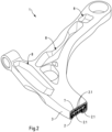
- chassis component As an example of a chassis component according to the invention is in the Figures 1 to 3 a suspension control arm 1 is shown.
- the chassis component (chassis control arm) is formed from a core part 2 and an outer shell 3 made of plastic, preferably fiber-reinforced plastic, enveloping the core part.
- the core part 2 can also be referred to as the inner support structure of the chassis component.
- connection points 4, 5, 6, which are used for the articulated connection of the suspension control arm to a body and a wheel carrier.
- a joint bushing (not shown) or a supporting joint (not shown) are inserted into the connection points 4, 5 on the bodywork side.
- a supporting joint (not shown) is likewise inserted into the connection point 6 on the wheel carrier side.
- the supporting joints are provided with ball pivots or ball joints.
- connection point 4 assigned to the articulated bush is designed in the form of a bush, while the connection points 5, 6 assigned to the supporting joints are designed in the form of bearing eyes.
- the connection points 4, 5, 6 are each formed in one piece with the core part 2 (cf. 3 ).
- the core part 2 of the chassis wishbone 1 is also made of plastic. It has a three-dimensional structure with a large number of ribs 2.1, for example wall-shaped ribs 2.1, with at least 60%, preferably at least 80%, in particular at least 95% of the ribs 2.1 each having a thickness (wall thickness) of maximum 5 mm. Particularly preferably, essentially all of the ribs 2.1 of the core part 2 have a thickness (wall thickness) of less than or equal to 5 mm.
- the ribs 2.1 each have a thickness in the range from 0.5 to 5 mm, preferably in the range from 0.5 to 4 mm.
- the height-to-thickness ratio of the ribs 2.1 is, for example, in the range from 3:1 to 5:1, in particular approximately 4:1.
- the core part 2 is made of thermoplastic material by injection molding.
- the plastic is preferably polyamide, e.g. B. Polyamide 6.6 with the trade name "Nylon".
- the plastic from which the core part 2 is made is preferably fiber-reinforced plastic, in particular fiber-reinforced polyamide.
- the fibers contained in the plastic of the core part 2 are preferably inorganic long fibers, for example glass fibers and/or carbon fibers.
- the proportion of long fibers in the plastic of the core part 2 can be, for example, approximately 60% by volume of the material of the core part 2 .
- the core part 2 has a net-like structure with annular sections 2.2, of which adjacent sections have a common partial section 2.3.
- the common section 2.3 connects outer sections 2.4 of the core part 2 and corresponds to or resembles a cross brace.
- the outer sections 2.4 of the core part are elongate or spoke-shaped; they can also be referred to as elongate or spoke-shaped sections 2.4 of the core part.
- the geometric shape of the outer sections 2.4 of the core part 2 is essentially adapted to the desired contour of the chassis component or chassis control arm 1.
- the ring-shaped sections 2.2 are preferably of different sizes. They have different internal widths.
- the position of the common partial sections (cross braces) 2.3 of the annular sections 2.2 is chosen such that the core part 2 has a high stability, in particular flexural rigidity, with a low weight.
- the core part 2 has a plurality of elongate or spoke-shaped sections 2.4 and sections (crossbars) 2.3, with a large number of the wall-shaped ribs 2.1 running obliquely or inclined to the center line of the relevant elongate or spoke-shaped section 2.4 or section 2.3.
- the respective outer section 2.4 and the partial section 2.3 of the core part 2 designed in the manner of a transverse strut preferably comprises a bar-shaped section 2.5, with a plurality of ribs 2.1 being formed on both sides of the bar-shaped section 2.5.
- a large number of wall-shaped ribs 2.1 run essentially parallel to one another (cf. also figure 5 ).
- the chassis component according to the invention can have an insert 7 in the area of one of the connection points, for example at the connection point 6 on the wheel carrier side.
- the optional insert 7 is preferably made of metal, for example a steel or aluminum alloy. In particular, it is cohesively connected to the core part 2 (cf. 2 ).
- the insert part 7 has a bearing eye-shaped section 7.1 and a bracket-shaped section 7.2.
- a cross section of the suspension control arm 1 in the area of the tab-shaped section 7.2 of the insert 7 is shown.
- the insert part 7, for example its tab-shaped section 7.2 has a large number of elevations and recesses.
- the core part 2 is produced in a mold having a first cavity.
- the core part 2 is provided with the optional insert part 7 with the outer shell 3 by the ribs 2.1 of the core part 2 being overmoulded and/or cast with plastic, preferably fiber-reinforced plastic.
- the core part 2 is positioned in a mold having a second cavity.
- the ribs 2.1 of the core part 2 are the plastic of the outer shell 3 is injection molded or cast around in such a way that initially existing gaps, which are delimited by adjacent ribs 2.1 of the ribs, are completely filled by the material of the outer shell 3 (cf. figures 1 and 2 ).
- the chassis component Due to the outer shell 3, which is preferably produced by injection molding, the chassis component has an essentially gap-free, largely smooth surface.
- the outer shell 3 defines indentations 8 formed within the annular sections 2.2 of the core part 2.
- the indentations 8 are in the form of indentations formed on one side or indentations located opposite one another on both sides.
- a through-opening 9 is formed in the area of one of the ring-shaped sections 2.2 of the core part 2 in the outer shell 3 or in the chassis component.
- the plastic used to produce the outer shell 3 is a thermoplastic, preferably polyamide, particularly preferably polyamide 6.6 (nylon), with the plastic preferably containing inorganic long fibers, for example carbon fibers and/or glass fibers and/or ceramic fibers.
- the proportion of long fibers in the plastic of the outer shell 3 can be, for example, approximately 40% by volume of the material of the outer shell 3 .
- the outer shell 3 can also be referred to as the outer support structure of the chassis component.
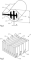
- FIG. 4 shows schematically an edge section of a chassis component according to the invention (e.g. wishbone) with a core part having wall-shaped ribs 2.1, which is made of thermoplastic material, preferably polyamide, e.g. nylon, and then overmoulded with fiber-reinforced thermoplastic material to produce an outer shell 3 or is cast over.
- the ribs 2.1 are formed on both sides of a web-shaped section 2.5 of the core part 2.
- the section of the core part 2 shown is an outer, elongate section 2.4 of the core part 2.
- the thickness (d R ) of a single wall-shaped rib 2.1 and the total thickness (d G ) of the Edge sections of the schematically indicated chassis component are indicated by dimension lines.
- the ribs 2.1 have a maximum thickness of 5 mm, for example, while the overall thickness of the edge section of the chassis component completed by the outer shell 3 is approximately 50 mm, for example.
- the ribs 2.1 can have different designs, in particular different thicknesses and/or different heights or depths.
- the outermost rib 2.1' has a smaller thickness and a lower height and depth than its immediately adjacent rib 2.1". It can also be seen that the outermost rib 2.1' has a convex outer profile.
- the ribs 2.1 are wall-shaped. Their respective wall thickness is a maximum of 5 mm, preferably significantly less than 5 mm.
- the ribs 2.1 run essentially parallel to one another and delimit gap-shaped intermediate spaces 10 before the outer shell 3 is injection molded/cast on.
- the ribs 2.1 of the core part 2 are also wall-shaped.
- the wall-shaped ribs are 2.1 in 6 however, also arc-shaped.
- a central rib 2.1 which is U-shaped or C-shaped in cross-section is surrounded by two ribs 2.1 which are spaced apart from one another and are also U-shaped or C-shaped when viewed in cross-section.
- These two ribs 2.1 are surrounded on the outside by three further arcuate ribs 2.1 spaced apart from one another, which in turn are surrounded by four further arcuate ribs 2.1 spaced apart from one another.
- the rib structure shown resembles the structure of a flower blossom when viewed in cross section or viewed from above.
- the ribs 2.1 of the core part 2 are pin-shaped. This rib structure resembles the structure of a so-called nail boards or a pin brush.
- the thickness of the pin-shaped ribs 2.1 is a maximum of 5 mm, preferably significantly less than 5 mm.
- the ribs 2.1 protrude on one side from a web-shaped section of the core part.
- the ribs 2.1 are formed on both sides of the web-shaped section 2.5 or protrude from it on both sides (cf. 4 ).
- the gaps 10 between the ribs 2.1 are then essentially completely filled with the material of the outer shell 3 when the core part 2 is overmolded.
- the individual ribs 2.1 as such are preferably not visible from the outside on the finished chassis component.
- chassis component according to the invention can also be designed, for example, as a chassis subframe or as part of such a subframe, in particular as a transverse bridge of a chassis subframe.
Landscapes
- Engineering & Computer Science (AREA)
- Mechanical Engineering (AREA)
- Injection Moulding Of Plastics Or The Like (AREA)
- Body Structure For Vehicles (AREA)
Description
- Die Erfindung betrifft ein Chassis-Bauteil entsprechend den Merkmalen des Anspruchs 1.
- Chassis-Bauteile für Kraftfahrzeuge, insbesondere Querlenker, sind in verschiedenen Ausführungen bekannt. Derartige Chassis-Bauteile werden üblicherweise aus tiefgezogenen Stahlblechen gebildet. Nachteilig an Chassis-Bauteilen aus Stahlblech ist ihr relativ hohes Gewicht.
- Des Weiteren sind Chassis-Bauteile für Kraftfahrzeuge, insbesondere Querlenker bekannt, die aus Aluminiumlegierungen mittels eines Gießverfahrens gefertigt werden. Derartige Chassis-Bauteile haben zwar ein relativ geringes Gewicht, sie sind jedoch aufgrund des Aluminiumwerkstoffs deutlich teurer als entsprechende Chassis-Bauteile aus Stahlblech.
- Ferner sind Chassis-Bauteile für Kraftfahrzeuge, insbesondere Querlenker bekannt, die in Metall-Kunststoff-Hybrid-Bauweise ausgeführt sind.
- Die
DE 20 2009 014 194 A1 beschreibt einen Querlenker, der einen Grundkörper aus metallischem Tiefziehblech mit Lagerstellen zur Anordnung des Querlenkers an einer Karosserie eines Kraftwagens aufweist. Der Grundkörper ist durch eine Verstärkungsstruktur aus Kunststoff verstärkt, die eine Vielzahl von kreuzförmigen Rippen aufweist. Der Grundkörper wird hierzu mittels eines Spritzgussverfahrens mit dem Kunststoff umspritzt. Als Kunststoff wird dabei z. B. Polyamid 6 mit 60% Glasfasern verwendet. - Ein ähnliches Fahrwerksbauteil in Metall-Kunststoff-Hybrid-Bauweise ist aus der
DE 10 2018 217 910 B3 bekannt. Das dort vorgeschlagene Fahrzeugbauteil besteht im Wesentlichen aus einem aus Metallblech gebildeten Strukturteil und einer Umhüllung aus Kunststoff. Das Strukturteil weist Haltestellen auf, an denen das Strukturteil in einem Spritz- oder Gusswerkzeug gehalten wird. An der jeweiligen Haltestelle wird eine Haltestellenabdeckung angeordnet, die das Strukturteil kontaktiert und teilweise von dem Material der Umhüllung umspritzt oder umgossen wird. Die Haltestellenabdeckung und die Umhüllung können dabei aus demselben Material gebildet sein. - Die
WO 2018/166691 A1 offenbart eine Fahrwerkskomponente, die insbesondere als Querlenker für einen Personenkraftwagen ausgeführt sein kann. Die Fahrwerkskomponente umfasst ein Kernmodul mit einer Umspritzung, wobei das Kernmodul aus wenigstens zwei Lastleitungselementen und wenigstens einem die Lastleitungselemente verbindenden Lastübertragungselement zusammengesetzt ist. Während die Lastleitungselemente eine hülsenförmige Form aufweisen können und aus Metall, z. B. aus einer Stahl- oder Aluminiumlegierung hergestellt sind, ist das Lastübertragungselement aus faserverstärktem Kunststoff hergestellt, z. B. aus Kohlenstofffasern enthaltendem Polyamid PA6.6. Auch die Umspritzung kann aus fasergefülltem Kunststoff hergestellt sein. Des Weiteren kann die Umspritzung Versteifungsrippen aufweisen. Zudem kann die Fahrwerkskomponente ein außenseitig an der Umspritzung angeordnetes Versteifungselement aufweisen. Das Versteifungselement kann dabei zunächst gesondert hergestellt und nachfolgend mit der Umspritzung gefügt werden. Die Umspritzung und das Versteifungselement können dabei miteinander an Versteifungsrippen des Versteifungselements verschweißt werden. - Die
DE 10 2014 015 870 A1 offenbart ein Chassis-Bauteil entsprechend dem Oberbegriff des Anspruchs 1 und beschreibt ein Fahrwerksbauteil für ein Kraftfahrzeug aus einem kurzfaserverstärkten Kunststoff. Das Fahrwerksbauteil weist mindestens einen in einem ersten Spritzgussvorgang hergestellten Kern und mindestens eine in einem zweiten Spritzgussvorgang hergestellte, den Kern umhüllende Umspritzung auf, wobei der Kern und die Umspritzung aus dem gleichen kurzfaserverstärkten Kunststoff bestehen. Gemäß einer Ausgestaltung weist der Kern in seiner Oberfläche rillenförmige Vertiefungen auf. Hierdurch soll eine hochbelastbare Verbindung zwischen Kern und Umspritzung sichergestellt werden. Die rillenförmigen Vertiefungen sind keine wandförmigen Rippen. Verrippungen sind bei dem Fahrwerksbauteil ausdrücklich nicht vorhanden. - Die
DE 10 2011 003 971 A1 offenbart einen Radführungslenker eines Kraftfahrzeugs, der zumindest zwei Endbereiche mit jeweils einem Lagerungsabschnitt und zumindest einen die Endbereiche verbindenden Strebenbereich aufweist. Die Endbereiche und der Strebenbereich sind dabei gemeinsam durch einen kastenförmig tiefgezogenen Profilträger gebildet, wobei der Profilträger aus einem plattenförmigen Kunststoffhalbzeug mit Endlosfaserverstärkungen gefertigt wurde. Im Innenraum des tiefgezogenen Profilträgers ist ein Füllkörper aus einem spritzgegossenen Kunststoff angeordnet, welcher die Innenoberflächen des Profilträgers schubfest miteinander verbindet. - Die
WO 2015/159038 A1 beschreibt ein Verfahren zur Herstellung einer großdimensionierten Kunststoffschale, die z. B. für eine Verwendung als Lichtleiter oder als Teil einer Beleuchtungsoptik vorgesehen ist. Bei dem Verfahren wird zur Verringerung der Herstellungsdauer eines schalenförmigen Bauteils zunächst ein erstes Schalenteil hergestellt, welches einen zu umspritzenden Abschnitt mit einer Vielzahl von Rippen aufweist. Diese Rippen dienen einer sicheren Verbindung zu einem zweiten Schaltenteil, welches durch teilweises Umspritzen des ersten Schalenteils hergestellt wird. - Die
US 2016/0052564 A1 offenbart einen Hilfsrahmen für ein Kraftfahrzeug, der eine Oberschale und eine Unterschale aufweist, wobei die Unterschale aus einem faserverstärkten Kunststoff hergestellt ist. Die Oberschale weist zur Verstärkung eine Rippenstruktur auf, ist jedoch selbst aus Metall gefertigt. - Die
DE 10 2018 202 307 A1 beschreibt einen Lenker für eine Radaufhängung, mit wenigstens einer Aufbau-Anbindungsstelle für einen Fahrzeugaufbau und wenigstens einer Radträger-Anbindungsstelle für einen Radträger, welche an einem sich entlang einer Lenkerebene erstreckenden Lenkerkörper angeordnet sind. Der Lenkerkörper weist einen Basiskörper, welcher aus diskontinuierlich verstärktem Kunststoff geformt ist, sowie eine hiermit stoffschlüssig verbundene, Endlosfasern enthaltende Verstärkung auf. Die Verstärkung ist dabei bezüglich der Lenkerebene auf einen ersten Bereich des Lenkerkörpers beschränkt, während sich der Basiskörper in einen zweiten Bereich erstreckt. - Die
DE 10 2013 214 673 A1 offenbart einen radführenden Lenker im Fahrwerk eines Fahrzeugs, dessen Grundstruktur (ohne Anbauteile) vollständig aus einem faserverstärkten thermoplastischen Werkstoff besteht, wobei die Grundstruktur vollumfänglich durch Spritzgießen oder Spritzpressen hergestellt ist. In einer bevorzugten Ausgestaltung besitzt der Lenker keine nennenswerte biegeelastische Eigenschaft, jedoch im Spritzguß- oder Spritzpressprozess ausgebildete Anbindungsstellen. Der thermoplastische Kunststoff des Lenkers kann mit Langfasern und/oder Kurzfasern und/oder Endlosfasern verstärkt sein, wobei als Verstärkungsfasern Karbon-, Glas- oder Aramidfasern zum Einsatz kommen können. - Die
DE 10 2013 201 058 A1 beschreibt einen Haltebügel für ein Lager eines Fahrwerks-Stabilisators eines zweispurigen Fahrzeugs, der durch zumindest ein Metallblech oder faserverstärktes Kunststofflaminat und durch thermoplastisch angespritzten faserverstärkten Kunststoff gebildet ist, welcher nicht das aus einem Elastomer geformte Lager bildet. Der faserverstärkte Kunststoff kann dabei in einer Rippenstruktur angespritzt sein. Des Weiteren können bei dem Haltebügel zwei Bleche oder Laminatstrukturen durch den angespritzten Kunststoff voneinander beabstandet in Radialrichtung des Elastomer-Lagers betrachtet hintereinander vorgesehen sein. - Hinsichtlich des technologischen Hintergrunds der vorliegenden Erfindung werden die Dokumente
KR 101 393 849 B1 US 2011/189428 A1 ,DE 10 2013 014 550 A1 ,WO 2012/167879 A2 ,EP 3 564 053 A1 undKR 2018 0036365 A - Die Fertigung von Bauteilen aus Kunststoff im Spritzguss gehört seit vielen Jahren zum Stand der Technik und zählt zu den üblichen Verfahren in der Herstellung von Produkten aus faserverstärkten thermoplastischen Kunststoffen. Bekannt ist dabei insbesondere das sogenannte Dickwandspritzgussverfahren, mit dem sich Wandstärken von bis zu 50 mm realisieren lassen.
- Chassis-Bauteile, insbesondere Querlenker, für Kraftfahrzeuge haben häufig komplexe Geometrien. Bei der Auslegung von Chassis-Bauteilen aus faserverstärkten thermoplastischen Kunststoffen für Kraftfahrzeuge wird darauf geachtet, dicke Wandstärken und Materialanhäufungen zu vermeiden. Denn bei zu dicken Wandstärken können beim Spritzguss materialabhängig Einfallstellen, Verformungen und Lunker (Lufttaschen) auftreten. Dadurch wird die Konstruktion von Chassis-Bauteilen, wie beispielsweise dynamisch belasteten Fahrwerksquerlenkern, aus faserverstärkten thermoplastischen Kunststoffen komplizierter, wenn diese Bauteile Vorgaben hinsichtlich Lebensdauerfestigkeit und Knicksteifigkeit erfüllen müssen.
- Aufgrund der komplexen Geometrien von Chassis-Bauteilen, insbesondere Querlenkern, lassen sich zumindest bereichsweise relativ dicke Wandstärken von z. B. mehr als 10 mm, insbesondere von mehr als 15 mm, nicht vermeiden. Das Dickwandspritzgussverfahren ist zur Herstellung von Chassis-Bauteilen mit komplexen Geometrien meist unbefriedigend oder sogar ungeeignet, weil dabei die oben genannten Maßstabilitätsmängel, insbesondere Verformungen und Lunker auftreten. Zudem lässt sich mit dem Dickwandspritzgussverfahren kein günstiger Teilepreis bei einer Massenproduktion von Chassis-Bauteilen aus faserverstärkten thermoplastischen Kunststoffen für Kraftfahrzeuge realisieren.
- Davon ausgehend liegt der Erfindung die technische Aufgabe zugrunde, ein Chassis-Bauteil der eingangs genannten Art derart weiterzuentwickeln, dass es sich mit hoher Maßstabilität sowie einem günstigen Bauteilpreis hinsichtlich einer Massenproduktion realisieren lässt.
- Diese Aufgabe wird durch ein Chassis-Bauteil mit den in Anspruch 1 angegebenen Merkmalen gelöst. Vorteilhafte Ausgestaltungen der Erfindung sind in den Unteransprüchen angegeben.
- Bei dem erfindungsgemäßen Chassis-Bauteil kann es sich beispielsweise um einen Fahrwerksquerlenker für ein Kraftfahrzeug handeln. Des Weiteren kann das erfindungsgemäße Chassis-Bauteil auch als Chassis-Hilfsrahmen für ein Kraftfahrzeug oder als Teil eines solchen Hilfsrahmens, insbesondere als Querbrücke eines Chassis-Hilfsrahmens ausgeführt sein.
- Das erfindungsgemäße Chassis-Bauteil umfasst ein Kernteil, das wenigstens eine erste Anbindungsstelle und wenigstens eine zweite Anbindungsstelle aufweist, und eine Außenhülle aus Kunststoff, vorzugsweise faserverstärktem Kunststoff, die das Kernteil teilweise oder vollständig umhüllt. Die Anbindungsstellen dienen beispielsweise der Anbindung des Chassis-Bauteils an eine Karosserie und/oder an einen Radträger oder der Anbindung an einen Hilfsrahmen für ein Kraftfahrzeug.
- Erfindungsgemäß ist das Kernteil aus faserverstärktem Kunststoff durch Spritzgießen hergestellt und weist eine dreidimensionale Struktur mit einer Vielzahl wandförmiger und/oder stiftförmiger Rippen auf, wobei wenigstens 60%, vorzugsweise wenigstens 80%, besonders bevorzugt wenigstens 95% der Rippen jeweils eine Dicke von maximal 5 mm, vorzugsweise eine Dicke von weniger als 5 mm haben, und wobei die Außenhülle die Rippen umhüllt, indem die Rippen mit Kunststoff der Außenhülle umspritzt und/oder umgossen sind, und wobei das Kernteil einen Langfaseranteil von mindestens 40 Vol.-% aufweist.
- Die Außenhülle kann auch als Mantelschicht oder Mantelteil bezeichnet werden.
- Durch die erfindungsgemäße Konstruktion (Bauweise) ist es möglich, zunächst das Kernteil und schließlich das Chassis-Bauteil als Ganzes in hoher Maßstabilität sowie mit einem günstigen Bauteilpreis in einer Massenproduktion zu realisieren. Die Erfinder haben erkannt, dass die relativ geringe Dicke der Rippen des Kernteils günstig für die Maßstabilität ist, jedoch zu kritischen Spannungskonzentrationen an den Rippen, insbesondere an Kreuzungs- bzw. Verbindungsstellen der Rippen führt. Diese Spannungskonzentrationen werden erfindungsgemäß durch die die Rippen umhüllende Außenhülle auf ein unkritisches Maß reduziert.
- Vorzugsweise haben im Wesentlichen alle Rippen des Kernteils des erfindungsgemäßen Chassis-Bauteils eine Dicke von weniger als 5 mm, beispielsweise eine Dicke, die im Bereich von ca. 0,5 bis 4 mm liegt.
- Das Verfahren zum Herstellen des erfindungsgemäßen Chassis-Bauteils ist folglich dadurch gekennzeichnet, dass zunächst das Kernteil durch Spritzgießen hergestellt und nachfolgend das Kernteil mit der Außenhülle versehen wird, indem die Rippen des Kernteils mit Kunststoff, vorzugsweise faserverstärktem Kunststoff umspritzt und/oder umgossen werden.
- Anders ausgedrückt besteht die erfindungsgemäße Lösung somit in einer zwei- oder mehrstufigen Hybrid-Spritzgusskonstruktion bzw. einem zwei- oder mehrstufigen Hybrid-Spritzgussverfahren, wobei zunächst eine erste Komponente als Kernteil in Form eines Rippenkörpers aus Kunststoff hergestellt wird, und anschließend eine zweite Komponente als Außenhülle aus Kunststoff in der Weise hergestellt wird, dass die Außenhülle die Rippen des Rippenkörpers dicht anliegend umhüllt. Die Außenhülle ist somit formschlüssig und stoffschlüssig mit dem Kernteil verbunden.
- Die Gesamtfertigungszeit des erfindungsgemäßen Chassis-Bauteils kann dabei beispielsweise unter 120 Sekunden liegen.
- Mittels der erfindungsmäßen Lösung, insbesondere mittels der erfindungsgemäßen Rippengestaltung, bei der die Rippendicke maximal 5 mm beträgt, können Chassis-Bauteile (z. B. Querlenker) aus thermoplastischem Kunststoff mit variablen Bauteildicken im Bereich von 10 bis 80 mm, vorzugsweise im Bereich von 10 bis 50 mm hergestellt werden.
- Abschnitte des erfindungsgemäßen Chassis-Bauteils, die aus Rippen des Kernteils und der die Rippen umhüllenden Außenhülle bestehen, können beispielsweise eine Gesamtdicke aufweisen, die größer als 15 mm, insbesondere größer als 20 mm ist. Die Gesamtdicke solcher Abschnitte kann beispielsweise im Bereich von 10 bis 80 mm, vorzugsweise im Bereich von 10 bis 60 mm, besonders bevorzugt im Bereich von 10 bis 50 mm liegen. Die Gesamtdicke solcher Abschnitt kann somit in dem typischen Wanddickenbereich liegen, welcher sich durch das herkömmliche Dickwandspritzgussverfahren realisieren lässt.
- Eine vorteilhafte Ausgestaltung der Erfindung ist dadurch gekennzeichnet, dass die Rippen des Kernteils eine Dicke im Bereich von ca. 0,5 bis 5 mm, vorzugsweise im Bereich von ca. 0,5 bis 4 mm, insbesondere im Bereich von ca. 0,5 bis 3,5 mm aufweisen. Diese Ausgestaltung trägt zu einer hohen Maßstabilität des Kernteils und damit zu einer hohen Maßstabilität des damit hergestellten Chassis-Bauteils bei. Die erzielbare Maßstabilität des Kernteils.(Rippenkörpers) lässt sich in der Regel mit abnehmender Dicke der Rippen steigern.
- Das Höhen-Dicken-Verhältnis der Rippen liegt vorzugsweise im Bereich von 3:1 bis 5:1, beispielsweise überwiegend bei ca. 4:1.
- Eine weitere vorteilhafte Ausgestaltung der Erfindung ist dadurch gekennzeichnet, dass das Kernteil aus thermoplastischem Kunststoff, vorzugsweise aus Polyamid, besonders bevorzugt aus Polyamid 6.6 (Nylon) hergestellt ist bzw. wird. Thermoplastischer Kunststoff, insbesondere Polyamid lässt sich gut verarbeiten. Polyamide verleihen dem Kernteil bzw. Chassis-Bauteil eine hervorragende Festigkeit, Steifigkeit und Zähigkeit. Zudem zeichnen sich Polyamide durch eine gute Beständigkeit gegenüber organischen Lösungsmitteln, insbesondere gegenüber Schmier- und Kraftstoffen bei Temperaturen bis über 150°C aus.
- Eine weitere Ausgestaltung der Erfindung sieht vor, dass das Kernteil einen Langfaseranteil von mindestens 50 Vol.-% aufweist. Durch die Faserverstärkung weist das Kernteil eine hohe Festigkeit, insbesondere hohe Biegefestigkeit auf.
- Die in dem Kunststoff des Kernteils enthaltenen Fasern bzw. Langfasern sind vorzugsweise anorganische Fasern bzw. anorganische Langfasern, beispielsweise Glasfasern und/oder Kohlenstofffasern und/oder Keramikfasern.
- Hinsichtlich eines möglichst geringen Bauteilgewichts bei ausreichend hoher Bauteilstabilität, insbesondere Biegefestigkeit, sieht eine weitere Ausgestaltung der Erfindung vor, dass das Kernteil ringförmige Abschnitte aufweist, von denen mindestens zwei benachbarte Abschnitte einen gemeinsamen Teilabschnitt haben. Vorzugsweise sind dabei zwei oder mehrere dieser ringförmigen Abschnitte hintereinander ausgebildet, wobei der jeweilige gemeinsame Teilabschnitt der benachbarten Abschnitte nach Art einer Querstrebe oder Traverse längliche Teilabschnitte des Kernteils miteinander verbindet. Die durch den mindestens einen gemeinsamen Teilabschnitt (Querstrebe) miteinander verbundenen länglichen Teilabschnitte des Kernteils verlaufen vorzugsweise entlang und mit geringem Abstand von Außenkanten oder Außenrändern des Chassis-Bauteils. Der Abstand der länglichen Teilabschnitte des Kernteils von den Außenkanten oder Außenrändern des Chassis-Bauteils wird durch die Außenhülle definiert und kann beispielsweise im Bereich von ca. 1 bis 10 mm, insbesondere im Bereich von ca. 2 bis 8 mm liegen.
- Das Kernteil kann auch als innere Stützstruktur des Chassis-Bauteils bezeichnet werden. Die Außenhülle kann dagegen auch als äußere Stützstruktur des Chassis-Bauteils bezeichnet werden.
- Eine weitere vorteilhafte Ausgestaltung der Erfindung ist dadurch gekennzeichnet, dass die ringförmigen Abschnitte des Kernteils unterschiedlich große Innenweiten aufweisen. Hierdurch kann das Kernteil vorteilhaft an die geometrischen Abmessungen des herzustellenden Chassis-Bauteils angepasst werden, um bei ausreichend hoher Bauteilstabilität, insbesondere Biegefestigkeit, ein möglichst geringes Bauteilgewichts zu realisieren.
- Nach einer weiteren vorteilhaften Ausgestaltung der Erfindung weist das Kernteil mindestens einen länglichen oder speichenförmigen Abschnitt auf, wobei in dem Fall, in welchem das Kernteil eine dreidimensionale Struktur mit einer Vielzahl wandförmiger Rippen und optional stiftförmiger Rippen aufweist, eine Vielzahl der wandförmigen Rippen schräg oder geneigt zur Mittellinie des länglichen oder speichenförmigen Abschnitts verläuft. Bei diesem länglichen oder speichenförmigen Abschnitt des Kernteils kann es sich insbesondere um einen der zuvor genannten länglichen Teilabschnitte des Kernteils handeln, die durch den mindestens einen gemeinsamen Teilabschnitt (Querstrebe) miteinander verbunden sind. Durch diese Ausgestaltung lässt sich eine besonders hohe Biegefestigkeit des Kernteils bei geringem Gewicht erzielen. Zugleich kann durch diese Ausgestaltung eine hohe Gesamtkontaktfläche zwischen Kernteil und Außenhülle realisiert werden. Günstig ist hierfür insbesondere eine Ausgestaltung, bei welcher das Kernteil eine dreidimensionale Struktur mit einer Vielzahl wandförmiger Rippen und optional stiftförmiger Rippen aufweist und eine Vielzahl der wandförmigen Rippen im Wesentlichen parallel zueinander verläuft.
- Eine weitere vorteilhafte Ausgestaltung der Erfindung ist dadurch gekennzeichnet, dass das Kernteil einen stegförmigen Abschnitt aufweist, wobei jeweils eine Vielzahl der Rippen beidseitig des stegförmigen Abschnittes ausgebildet ist. Dieser stegförmige Abschnitt mit den beidseitig ausgebildeten Rippen kann insbesondere in dem oben genannten länglichen oder speichenförmigen Abschnitt und/oder in dem oben genannten gemeinsamen Teilabschnitt (Querstrebe) des Kernteils ausgebildet sein. Diese Ausgestaltung verleiht dem Kernteil eine besonders hohe Biegefestigkeit bei geringem Gewicht. Außerdem kann durch diese Ausgestaltung eine hohe Gesamtkontaktfläche zwischen Kernteil und Außenhülle realisiert werden.
- Nach einer weiteren vorteilhaften Ausgestaltung der Erfindung ist vorgesehen, dass wenigstens eine der Anbindungsstellen des Kernteils als buchsenförmige Anbindungsstelle oder in Form eines Lagerauges einstückig mit dem Kernteil ausgebildet ist. Diese Ausgestaltung verleiht dem Chassis-Bauteil bei geringem Gewicht eine hohe Stabilität, insbesondere eine hohe Biegefestigkeit, und bietet die Möglichkeit einer Reduktion der Herstellungskosten des Chassis-Bauteils.
- Eine weitere Ausgestaltung der Erfindung sieht vor, dass das Chassis-Bauteil ein Einlegeteil, vorzugsweise aus Metall, z. B. Stahl, aufweist, das im Bereich einer der Anbindungsstellen angeordnet ist, wobei das Einlegeteil stoffschlüssig und/oder formschlüssig mit dem Kernteil und/oder der Außenhülle verbunden ist. Hierdurch können das Kraftaufnahmevermögen und die Dauerfestigkeit an der betreffenden Anbindungsstelle optimiert werden. Das Einlegeteil weist vorzugsweise einen lageraugenförmigen Abschnitt und/oder einen laschenförmigen Abschnitt auf. Durch den lageraugenförmigen Abschnitt lässt sich eine vorteilhafte Gelenkanbindung realisieren, während der laschenförmige Abschnitt zu einer besonders stabilen Verbindung des Einlegeteils mit dem Kernteil des Chassis-Bauteils beiträgt. Zur Erzielung einer besonders stabilen Verbindung von Einlegeteil und Kernteil des Chassis-Bauteils sieht eine weitere Ausgestaltung vor, dass das Einlegeteil eine Vielzahl von Erhebungen und/oder Ausnehmungen aufweist. Hierdurch wird die Verbindung von Einlegeteil und Kernteil durch eine verbesserte formschlüssige Verbindung optimiert, da sich das Material des Kernteils mit den Erhebungen und/oder Ausnehmungen des Einlegeteils verankert.
- Eine weitere vorteilhafte Ausgestaltung der Erfindung ist dadurch gekennzeichnet, dass die Außenhülle die Rippen des Kernteils derart umhüllt, dass ein oder mehrere Zwischenräume, der bzw. die durch benachbarte Rippen der Rippen begrenzt ist/sind, durch das Material der Außenhülle vollständig gefüllt ist/sind. Vorzugsweise sind im Wesentlichen alle Zwischenräume, die durch benachbarte Rippen der Rippen begrenzt sind, durch das Material der Außenhülle vollständig gefüllt. Hierdurch kann die Oberfläche des Chassis-Bauteils weitgehend geglättet ausgeführt werden, wodurch einem Anhaften von grobem Schmutz an durch die Rippen verursachten Vorsprüngen entgegengewirkt bzw. eine Reinigung des Chassis-Bauteils vereinfacht wird.
- Nach einer weiteren vorteilhaften Ausgestaltung der Erfindung begrenzt die Außenhülle des Chassis-Bauteils im Bereich mindestens eines der ringförmigen Abschnitte des Kernteils eine einseitig ausgebildete Vertiefung oder beidseitig gegenüberliegende Vertiefungen. Diese Ausgestaltung ist für eine Reduzierung des Gewichts des Chassis-Bauteils von Vorteil. Zu diesem Zweck kann im Bereich mindestens eines der ringförmigen Abschnitte des Kernteils auch eine Durchgangsöffnung in der Außenhülle bzw. dem Chassis-Bauteil ausgebildet sein.
- Eine weitere Ausgestaltung der Erfindung sieht vor, dass die Außenhülle aus thermoplastischem Kunststoff, vorzugsweise aus Polyamid, besonders bevorzugt aus PA 6.6 (Nylon) hergestellt ist, wobei der Kunststoff vorzugsweise anorganische Fasern, besonders bevorzugt anorganische Langfasern, beispielsweise Kohlenstofffasern und/oder Glasfasern und/oder Keramikfasern enthält. Die oben mit Bezug auf das Kernteil genannten Vorteile von Polyamid, insbesondere dessen gute Beständigkeit gegenüber Schmier- und Kraftstoffen bei Temperaturen bis über 150°C, ergeben sich bei dieser Ausgestaltung auch für die Außenhülle. Die bereits hervorragende Steifigkeit von Polyamid wird durch die Beimischung von anorganischen Fasern gesteigert. Zugleich kann hierdurch das Gewicht des Chassis-Bauteils reduziert werden. Der Anteil der Fasern im Kunststoff der Außenhülle kann beispielsweise im Bereich von 20 bis 60 Vol.-%, insbesondere im Bereich von 30 bis 50 Vol.-% des Materials der Außenhülle liegen.
- Unter Langfasern werden im Rahmen der vorliegenden Erfindung Fasern, insbesondere anorganische Fasern verstanden, deren Länge im Bereich von 1 bis 50 mm, vorzugsweise im Bereich von ca. 5 bis 20 mm, besonders bevorzugt im Bereich von ca. 7 bis 15 mm liegt. Beispielsweise haben mindestens 60 %, vorzugsweise mindestens 75 % der Fasern, die im Kunststoff des Kernteils oder im Kunststoff der Außenhülle enthalten sind, eine Länge im Bereich von 8 bis 12 mm.
- Nachfolgend wird die Erfindung anhand einer mehrere Ausführungsbeispiele darstellenden Zeichnung näher erläutert. Es zeigen.
- Fig. 1
- einen Abschnitt eines Chassis-Bauteils für ein Kraftfahrzeug in Form eines Fahrwerksquerlenkers, in einer perspektivischen Darstellung;
- Fig. 2
- einen anderen Abschnitt des Chassis-Bauteils aus
Fig. 1 , in einer perspektivischen Darstellung; - Fig. 3
- das Chassis-Bauteil aus den
Figuren 1 und2 , in einer perspektivischen Explosionsdarstellung; - Fig. 4
- einen Randabschnitt eines erfindungsgemäßen Chassis-Bauteils, in einer perspektivischen Darstellung;
- Fig. 5
- einen Abschnitt des Kernteils eines erfindungsgemäßen Chassis-Bauteils mit einer Rippenstruktur gemäß einem weiteren Ausführungsbeispiel, in einer perspektivischen Darstellung;
- Fig. 6
- einen Abschnitt des Kernteils eines erfindungsgemäßen Chassis-Bauteils mit einer Rippenstruktur gemäß noch einem weiteren Ausführungsbeispiel, in einer perspektivischen Darstellung; und
- Fig. 7
- einen Abschnitt des Kernteils eines erfindungsgemäßen Chassis-Bauteils mit einer Rippenstruktur gemäß noch einem weiteren Ausführungsbeispiel, in einer perspektivischen Darstellung.
- Als Beispiel für ein erfindungsgemäßes Chassis-Bauteil ist in den
Figuren 1 bis 3 ein Fahrwerksquerlenker 1 gezeigt. Das Chassis-Bauteil (Fahrwerksquerlenker) ist aus einem Kernteil 2 und einer das Kernteil umhüllenden Außenhülle 3 aus Kunststoff, vorzugsweise faserverstärktem Kunststoff, gebildet. Das Kernteil 2 kann auch als innere Stützstruktur des Chassis-Bauteils bezeichnet werden. - Das Kernteil 2 des Fahrwerksquerlenkers 1 weist Anbindungsstellen 4, 5, 6 auf, die der gelenkigen Anbindung des Fahrwerksquerlenkers an einer Karosserie und einem Radträger dienen. In die karosserieseitigen Anbindungsstellen 4, 5 werden hierzu beispielsweise eine Gelenkbuchse (nicht gezeigt) bzw. ein Traggelenk (nicht gezeigt) eingesetzt. In die radträgerseitige Anbindungsstelle 6 wird ebenfalls ein Traggelenk (nicht gezeigt) eingesetzt. Die Traggelenke sind mit Kugelzapfen oder Kugelgelenken versehen.
- Die der Gelenkbuchse zugeordnete Anbindungsstelle 4 ist buchsenförmig ausgebildet, während die den Traggelenken zugeordneten Anbindungsstellen 5, 6 in Form von Lageraugen ausgebildet sind. Die Anbindungsstellen 4, 5, 6 sind jeweils einstückig mit dem Kernteil 2 ausgebildet (vgl.
Fig. 3 ). - Das Kernteil 2 des Fahrwerksquerlenkers 1 ist ebenfalls aus Kunststoff hergestellt. Es weist eine dreidimensionale Struktur mit einer Vielzahl von Rippen 2.1, beispielsweise wandförmige Rippen 2.1 auf, wobei wenigstens 60%, vorzugsweise wenigstens 80%, insbesondere wenigstens 95% der Rippen 2.1 jeweils eine Dicke (Wanddicke) von maximal 5 mm haben. Besonders bevorzugt haben im Wesentlichen alle Rippen 2.1 des Kernteils 2 eine Dicke (Wanddicke) kleiner/gleich 5 mm. Beispielsweise haben die Rippen 2.1 jeweils eine Dicke im Bereich von 0,5 bis 5 mm, vorzugsweise im Bereich von 0,5 bis 4 mm.
- Das Höhen-Dicken-Verhältnis der Rippen 2.1 liegt beispielsweise im Bereich von 3:1 bis 5:1, insbesondere überwiegend bei ca. 4:1.
- Das Kernteil 2 wird aus thermoplastischem Kunststoff durch Spritzgießen hergestellt. Bei dem Kunststoff handelt es sich vorzugsweise um Polyamid, z. B. Polyamid 6.6 mit der Handelsbezeichnung "Nylon". Der Kunststoff, aus dem das Kernteil 2 hergestellt wird, ist vorzugsweise faserverstärkter Kunststoff, insbesondere faserverstärktes Polyamid. Die in dem Kunststoff des Kernteils 2 enthaltenen Fasern sind vorzugsweise anorganische Langfasern, beispielsweise Glasfasern und/oder Kohlenstofffasern. Der Anteil der Langfasern im Kunststoff des Kernteils 2 kann beispielsweise ca. 60 Vol.-% des Materials des Kernteils 2 betragen.
- Das Kernteil 2 hat eine netzartige Struktur mit ringförmigen Abschnitten 2.2, von denen benachbarte Abschnitte einen gemeinsamen Teilabschnitt 2.3 aufweisen. Der gemeinsame Teilabschnitt 2.3 verbindet äußere Abschnitte 2.4 des Kernteils 2 und entspricht oder ähnelt einer Querstrebe. Die äußeren Abschnitte 2.4 des Kernteils sind länglich oder speichenförmig ausgebildet; sie können auch als längliche oder speichenförmige Abschnitte 2.4 des Kernteils bezeichnet werden. Die geometrische Form der äußeren Abschnitte 2.4 des Kernteils 2 ist im Wesentlichen an die gewünschte Kontur des Chassis-Bauteils bzw. Fahrwerksquerlenkers 1 angepasst.
- Die ringförmigen Abschnitte 2.2 sind vorzugsweise verschieden groß ausgebildet. Sie weisen unterschiedlich große Innenweiten auf. Die Lage der gemeinsamen Teilabschnitte (Querstreben) 2.3 der ringförmigen Abschnitte 2.2 ist so gewählt, dass das Kernteil 2 bei geringem Gewicht eine hohe Stabilität, insbesondere Biegesteifigkeit aufweist.
- In
Fig. 3 ist zu sehen, dass das Kernteil 2 mehrere längliche oder speichenförmige Abschnitte 2.4 und Teilabschnitte (Querstreben) 2.3 aufweist, wobei eine Vielzahl der wandförmigen Rippen 2.1 schräg oder geneigt zur Mittellinie des betreffenden länglichen oder speichenförmigen Abschnitts 2.4 bzw. Teilabschnitts 2.3 verläuft. - Der jeweilige äußere Abschnitt 2.4 sowie der nach Art einer Querstrebe ausgebildete Teilabschnitt 2.3 des Kernteils 2 umfasst vorzugsweise einen stegförmigen Abschnitt 2.5, wobei eine Vielzahl der Rippen 2.1 beidseitig des stegförmigen Abschnitts 2.5 ausgebildet ist. Eine Vielzahl der wandförmigen Rippen 2.1 verläuft dabei im Wesentlichen parallel zueinander (vgl. auch
Fig. 5 ). - Das erfindungsgemäße Chassis-Bauteil kann im Bereich einer der Anbindungsstellen, beispielsweise an der radträgerseitigen Anbindungsstelle 6, ein Einlegeteil 7 aufweisen. Das optionale Einlegeteil 7 ist vorzugsweise aus Metall, beispielsweise aus einer Stahl- oder Aluminiumlegierung gefertigt. Es ist insbesondere mit dem Kernteil 2 stoffschlüssig verbunden (vgl.
Fig. 2 ). In dem gezeigten Ausführungsbeispiel weist das Einlegeteil 7 einen lageraugenförmigen Abschnitt 7.1 und einen laschenförmigen Abschnitt 7.2 auf. InFig. 2 ist ein Querschnitt des Fahrwerksquerlenkers 1 im Bereich des laschenförmigen Abschnitts 7.2 des Einlegeteils 7 gezeigt. In denFiguren 2 und3 ist zu erkennen, dass das Einlegeteil 7, beispielsweise sein laschenförmiger Abschnitt 7.2 eine Vielzahl von Erhebungen und Ausnehmungen aufweist. Beim Herstellen des Kernteils 2 durch Spritzgießen verankert sich der Kunststoff des Kernteils 2 formschlüssig an den Erhebungen und Ausnehmungen des Einlegeteils 7. - Das Kernteil 2 wird in einem eine erste Kavität aufweisenden Formwerkzeug hergestellt. In einem nachfolgenden Herstellungsschritt wird das Kernteil 2 mit dem optionalen Einlegeteil 7 mit der Außenhülle 3 versehen, indem die Rippen 2.1 des Kernteils 2 mit Kunststoff, vorzugsweise faserverstärktem Kunststoff umspritzt und/oder umgossen werden. Hierzu wird das Kernteil 2 in einem eine zweite Kavität aufweisenden Formwerkzeug positioniert. Die Rippen 2.1 des Kernteils 2 werden dabei derart mit dem Kunststoff der Außenhülle 3 umspritzt oder umgossen, dass zunächst vorhandene Zwischenräume, welche durch benachbarte Rippen 2.1 der Rippen begrenzt sind, durch das Material der Außenhülle 3 vollständig gefüllt werden (vgl.
Figuren 1 und2 ). - Durch die vorzugsweise durch Spritzgießen erzeugte Außenhülle 3 weist das Chassis-Bauteil eine im Wesentlichen spaltfreie, weitgehend glatt ausgeführte Oberfläche auf. Die Außenhülle 3 definiert innerhalb der ringförmigen Abschnitte 2.2 des Kernteils 2 ausgebildete Vertiefungen 8. Die Vertiefungen 8 sind als einseitig ausgebildete Vertiefung oder als beidseitig, gegenüberliegende Vertiefungen ausgebildet sein. Zudem ist in der Außenhülle 3 bzw. im Chassis-Bauteil eine Durchgangsöffnung 9 im Bereich eines der ringförmigen Abschnitte 2.2 des Kernteils 2 ausgebildet.
- Bei dem zur Herstellung der Außenhülle 3 verwendeten Kunststoff handelt es sich um thermoplastischen Kunststoff, vorzugsweise Polyamid, besonders bevorzugt Polyamid 6.6 (Nylon), wobei der Kunststoff vorzugsweise anorganische Langfasern, beispielsweise Kohlenstofffasern und/oder Glasfasern und/oder Keramikfasern enthält. Der Anteil der Langfasern im Kunststoff der Außenhülle 3 kann beispielsweise ca. 40 Vol.-% des Materials der Außenhülle 3 betragen. Die Außenhülle 3 kann auch als äußere Stützstruktur des Chassis-Bauteils bezeichnet werden.
- In den
Figuren 4 bis 7 sind verschiedene Rippenstrukturen des Kernteils 2 dargestellt. -
Fig. 4 zeigt schematisch einen Randabschnitt eines erfindungsgemäßen Chassis-Bauteils (z. B. Querlenker) mit einem wandförmige Rippen 2.1 aufweisenden Kernteil, das aus thermoplastischem Kunststoff, vorzugsweise Polyamid, z.B. Nylon, hergestellt und anschließend mit faserverstärktem, thermoplastischen Kunststoff zur Erzeugung einer Außenhülle 3 umspritzt oder umgossen ist. Die Rippen 2.1 sind beidseitig eines stegförmigen Abschnittes 2.5 des Kernteils 2 ausgebildet. Der inFig. 4 gezeigte Abschnitt des Kernteils 2 ist ein äußerer, länglicher Abschnitt 2.4 des Kernteils 2. Die Dicke (dR) einer einzelnen wandförmigen Rippe 2.1 sowie die Gesamtdicke (dG) des Randabschnittes des schematisch angedeuteten Chassis-Bauteils sind durch Bemaßungslinien angezeigt. Die Rippen 2.1 haben eine maximale Dicke von beispielsweise 5 mm, während die Gesamtdicke des durch die Außenhülle 3 vervollständigten Randabschnitts des Chassis-Bauteils beispielsweise ca. 50 mm beträgt. Die Rippen 2.1 können dabei unterschiedlich ausgebildet, insbesondere unterschiedlich dick und/oder unterschiedlich hoch bzw. tief ausgebildet sein. Beispielsweise hat die äußerste Rippe 2.1' eine geringere Dicke und eine geringere Höhe sowie Tiefe als ihre unmittelbar benachbarte Rippe 2.1". Weiter ist zu erkennen, dass die äußerste Rippe 2.1' ein konvex ausgebildetes Außenprofil aufweist. - Bei dem in
Fig. 5 gezeigten Ausführungsbeispiel sind die Rippen 2.1 wandförmig ausgebildet. Ihre jeweilige Wanddicke beträgt maximal 5 mm, vorzugsweise deutlich weniger als 5 mm. Die Rippen 2.1 verlaufen im Wesentlichen parallel zueinander und begrenzen, vor dem Anspritzen/Angießen der Außenhülle 3, spaltförmige Zwischenräume 10. - In
Fig. 6 ist ein Ausführungsbeispiel gezeigt, bei dem die Rippen 2.1 des Kernteils 2 ebenfalls wandförmig ausgebildet sind. Im Unterschied zu dem inFig. 5 gezeigten Ausführungsbeispiel sind die wandförmigen Rippen 2.1 inFig. 6 jedoch zudem bogenförmig ausgebildet. Es ist zu erkennen, das eine zentrale, im Querschnitt U- oder C-förmige Rippe 2.1 von zwei Rippen 2.1 umgeben ist, die zueinander beabstandet und im Querschnitt betrachtet ebenfalls U- oder C-förmig ausgebildet sind. Diese beiden Rippen 2.1 sind nach außen durch drei weitere, zueinander beabstandete, bogenförmige Rippen 2.1 umgeben, welche wiederum durch vier weitere, zueinander beabstandete, bogenförmige Rippen 2.1 umgeben sind. Die inFig. 6 gezeigte Rippenstruktur ähnelt im Querschnitt bzw. in Draufsicht betrachtet der Struktur einer Blumenblüte. - Bei dem in
Fig. 7 gezeigten Ausführungsbeispiel sind die Rippen 2.1 des Kernteils 2 stiftförmig ausgebildet. Diese Rippenstruktur ähnelt der Struktur eines sogenannten Nagelbretts oder einer Nadelbürste. Auch die Dicke der stiftförmigen Rippen 2.1 beträgt maximal 5 mm, vorzugsweise deutlich weniger als 5 mm. - In den in den
Figuren 5 bis 7 dargestellten Ausführungsbeispielen von Kernteilen 2 eines erfindungsgemäßen Chassis-Bauteils stehen die Rippen 2.1 einseitig von einem stegförmigen Abschnitt des Kernteils ab. Es liegt jedoch auch im Rahmen der vorliegenden Erfindung, dass die Rippen 2.1 beidseitig des stegförmigen Abschnittes 2.5 ausgebildet sind bzw. beidseitig davon abstehen (vgl.Fig. 4 ). - Die Zwischenräume 10 zwischen den Rippen 2.1 werden nachfolgend beim Überspritzen des Kernteils 2 mit dem Material der Außenhülle 3 im Wesentlichen vollständig gefüllt. An dem fertigen Chassis-Bauteil sind die einzelnen Rippen 2.1 als solche von außen vorzugsweise nicht sichtbar.
- Die Ausführung der Erfindung ist nicht auf die in der Zeichnung dargestellten Ausführungsbeispiele beschränkt. Vielmehr sind zahlreiche Varianten denkbar, die auch bei von den gezeigten Beispielen abweichender Gestaltung von der in den beigefügten Ansprüchen angegebenen Erfindung Gebrauch machen. So liegt es beispielsweise auch im Rahmen der Erfindung, verschiedene der hier offenbarten Rippenstrukturen, z. B. zwei oder mehr der in den
Figuren 4 bis 7 gezeigten Rippenstrukturen miteinander kombiniert an dem Kernteil 2 des Chassis-Bauteils auszubilden. Ferner kann das erfindungsgemäße Chassis-Bauteil zum Beispiel auch als Chassis-Hilfsrahmen oder als Teil eines solchen Hilfsrahmens, insbesondere als Querbrücke eines Chassis-Hilfsrahmens ausgeführt werden.
Claims (14)
- Chassis-Bauteil für ein Kraftfahrzeug, insbesondere Querlenker (1), wobei das Chassis-Bauteil ein Kernteil (2) aufweist, das wenigstens eine erste Anbindungsstelle (4) und wenigstens eine zweite Anbindungsstelle (5, 6) aufweist, und mit einer das Kernteil (2) teilweise oder vollständig umhüllenden Außenhülle (3) aus Kunststoff, vorzugsweise faserverstärktem Kunststoff, wobei das Kernteil (2) aus faserverstärktem Kunststoff durch Spritzgießen hergestellt ist,
dadurch gekennzeichnet, dass das Kernteil (2) eine dreidimensionale Struktur mit einer Vielzahl wandförmiger und/oder stiftförmiger Rippen (2.1) aufweist, wobei wenigstens 60%, vorzugsweise wenigstens 80%, besonders bevorzugt wenigstens 95% der Rippen (2.1) jeweils eine Dicke von maximal 5 mm haben, wobei die Außenhülle (3) die Rippen (2.1) umhüllt, indem die Rippen (2.1) mit Kunststoff der Außenhülle (3) umspritzt und/oder umgossen sind, und wobei das Kernteil (2) einen Langfaseranteil von mindestens 40 Vol.-% aufweist. - Chassis-Bauteil nach Anspruch 1, dadurch gekennzeichnet, dass die Rippen (2.1) eine Dicke im Bereich von 0,5 bis 5 mm, vorzugsweise im Bereich von 0,5 bis 4 mm haben.
- Chassis-Bauteil nach Anspruch 1 oder 2, dadurch gekennzeichnet, dass die Rippen (2.1) ein Höhen-Dicken-Verhältnis im Bereich von 3:1 bis 5:1 haben.
- Chassis-Bauteil nach einem der Ansprüche 1 bis 3, dadurch gekennzeichnet, dass das Kernteil (2) aus thermoplastischem Kunststoff, vorzugsweise aus Polyamid, besonders bevorzugt aus Polyamid 6.6 hergestellt ist.
- Chassis-Bauteil nach einem der Ansprüche 1 bis 4, dadurch gekennzeichnet, dass das Kernteil (2) einen Langfaseranteil von mindestens 50 Vol.-% aufweist.
- Chassis-Bauteil nach einem der Ansprüche 1 bis 5, dadurch gekennzeichnet, dass das Kernteil (2) ringförmige Abschnitte (2.2) aufweist, von denen mindestens zwei benachbarte Abschnitte einen gemeinsamen Teilabschnitt (2.3) haben, wobei die ringförmigen Abschnitte (2.2) vorzugsweise unterschiedlich große Innenweiten aufweisen.
- Chassis-Bauteil nach einem der Ansprüche 1 bis 6, dadurch gekennzeichnet, dass das Kernteil (2) einen länglichen oder speichenförmigen Abschnitt (2.4) aufweist, wobei in dem Fall, in welchem das Kernteil (2) eine dreidimensionale Struktur mit einer Vielzahl wandförmiger Rippen (2.1) und optional stiftförmiger Rippen (2.1) aufweist, eine Vielzahl der wandförmigen Rippen (2.1) schräg oder geneigt zur Mittellinie des länglichen oder speichenförmigen Abschnitts (2.4) verläuft.
- Chassis-Bauteil nach einem der Ansprüche 1 bis 7, dadurch gekennzeichnet, dass in dem Fall, in welchem das Kernteil (2) eine dreidimensionale Struktur mit einer Vielzahl wandförmiger Rippen (2.1) und optional stiftförmiger Rippen (2.1) aufweist, eine Vielzahl der wandförmigen Rippen (2.1) im Wesentlichen parallel zueinander verläuft.
- Chassis-Bauteil nach einem der Ansprüche 1 bis 8, dadurch gekennzeichnet, dass das Kernteil (2) einen stegförmigen Abschnitt (2.5) aufweist, wobei jeweils eine Vielzahl der Rippen (2.1) beidseitig des stegförmigen Abschnitts (2.5) ausgebildet ist.
- Chassis-Bauteil nach einem der Ansprüche 1 bis 9, dadurch gekennzeichnet, dass wenigstens eine der Anbindungsstellen (4, 5, 6) als buchsenförmige Anbindungsstelle (4) oder in Form eines Lagerauges einstückig mit dem Kernteil (2) ausgebildet ist.
- Chassis-Bauteil nach einem der Ansprüche 1 bis 10, gekennzeichnet durch ein Einlegeteil (7), vorzugsweise aus Metall, das im Bereich einer der Anbindungsstellen (4, 5, 6) angeordnet ist, wobei das Einlegeteil (7) stoffschlüssig und/oder formschlüssig mit dem Kernteil (2) und/oder der Außenhülle (3) verbunden ist.
- Chassis-Bauteil nach Anspruch 11, dadurch gekennzeichnet, dass das Einlegeteil (7) einen lageraugenförmigen Abschnitt (7.1) und/oder einen laschenförmigen Abschnitt (7.2) aufweist.
- Chassis-Bauteil nach einem der Ansprüche 1 bis 12, dadurch gekennzeichnet, dass die Außenhülle (3) die Rippen (2.1) derart umhüllt, dass ein oder mehrere Zwischenräume (10), der/die durch benachbarte Rippen der Rippen (2.1) begrenzt ist/sind, durch das Material der Außenhülle (3) vollständig gefüllt ist/sind.
- Chassis-Bauteil nach einem der Ansprüche 1 bis 13, dadurch gekennzeichnet, dass die Außenhülle (3) aus thermoplastischem Kunststoff, vorzugsweise aus Polyamid, besonders bevorzugt aus Polyamid 6.6 hergestellt ist, wobei der Kunststoff vorzugsweise anorganische Fasern, besonders bevorzugt anorganische Langfasern, beispielsweise Kohlenstofffasern und/oder Glasfasern und/oder Keramikfasern enthält.
Priority Applications (1)
| Application Number | Priority Date | Filing Date | Title |
|---|---|---|---|
| EP20382611.0A EP3936354B1 (de) | 2020-07-08 | 2020-07-08 | Chassis-bauteil für ein kraftfahrzeug |
Applications Claiming Priority (1)
| Application Number | Priority Date | Filing Date | Title |
|---|---|---|---|
| EP20382611.0A EP3936354B1 (de) | 2020-07-08 | 2020-07-08 | Chassis-bauteil für ein kraftfahrzeug |
Publications (2)
| Publication Number | Publication Date |
|---|---|
| EP3936354A1 EP3936354A1 (de) | 2022-01-12 |
| EP3936354B1 true EP3936354B1 (de) | 2023-08-30 |
Family
ID=71607885
Family Applications (1)
| Application Number | Title | Priority Date | Filing Date |
|---|---|---|---|
| EP20382611.0A Active EP3936354B1 (de) | 2020-07-08 | 2020-07-08 | Chassis-bauteil für ein kraftfahrzeug |
Country Status (1)
| Country | Link |
|---|---|
| EP (1) | EP3936354B1 (de) |
Families Citing this family (1)
| Publication number | Priority date | Publication date | Assignee | Title |
|---|---|---|---|---|
| CN118665091A (zh) * | 2024-07-01 | 2024-09-20 | 一汽解放汽车有限公司 | 一种高承载轻量化悬架控制臂、制造方法和车辆 |
Citations (3)
| Publication number | Priority date | Publication date | Assignee | Title |
|---|---|---|---|---|
| DE102013201058A1 (de) * | 2013-01-23 | 2014-07-24 | Bayerische Motoren Werke Aktiengesellschaft | Haltebügel für ein Lager eines Fahrwerks-Stabilisators |
| DE102013214673A1 (de) * | 2013-07-26 | 2015-01-29 | Bayerische Motoren Werke Aktiengesellschaft | Radführender Lenker aus faserverstärktem thermoplastischen Werkstoff |
| DE102018202307A1 (de) * | 2018-02-15 | 2019-08-22 | Ford Global Technologies, Llc | Lenker für eine Radaufhängung |
Family Cites Families (12)
| Publication number | Priority date | Publication date | Assignee | Title |
|---|---|---|---|---|
| ES2579228T3 (es) * | 2008-07-25 | 2016-08-08 | Sika Technology Ag | Capas de espuma o adhesivo interconectadas |
| DE102011003971A1 (de) * | 2011-02-11 | 2012-08-16 | Zf Friedrichshafen Ag | Faserverbund-Hybridlenker |
| WO2012167879A2 (de) * | 2011-06-06 | 2012-12-13 | Webasto Ag | Fahrzeug-bauteil |
| KR101393849B1 (ko) * | 2012-12-12 | 2014-05-12 | 현대자동차주식회사 | 차량용 로어암 |
| DE102013014550A1 (de) * | 2013-09-03 | 2015-03-05 | Trw Airbag Systems Gmbh | VERFAHREN ZUM ANBRlNGEN ElNES KUNSTSTOFFBAUTElLS lN UND/ODER AN ElNEN GASGENERATOR UND KUNSTSTOFFBAUTEIL HIERFÜR |
| FR3020006B1 (fr) * | 2014-04-18 | 2017-03-03 | Automotive Lighting Rear Lamps France | Procede de fabrication d’une coque en matiere plastique par moulage et surmoulage, portion de coque et coque obtenues par ce procede |
| DE102014112090A1 (de) * | 2014-08-25 | 2016-02-25 | Benteler Automobiltechnik Gmbh | Achsträger für ein Kraftfahrzeug sowie Verfahren zur Herstellung eines Achsträgers |
| DE102014015870B4 (de) * | 2014-10-25 | 2021-10-21 | Audi Ag | Fahrwerksbauteil für ein Kraftfahrzeug aus einem kurzfaserverstärkten Kunststoff |
| KR101898857B1 (ko) * | 2016-09-30 | 2018-09-14 | (주)화신정공 | 리어 트레일링암 |
| KR101857172B1 (ko) * | 2016-12-28 | 2018-05-16 | 주식회사 일진 | 차량용 하이브리드 현가암 및 그 제조방법 |
| DE102017204464A1 (de) | 2017-03-17 | 2018-09-20 | Bayerische Motoren Werke Aktiengesellschaft | Fahrwerkskomponente für ein Kraftfahrzeug und Verfahren zum Herstellen einer Fahrwerkskomponente |
| DE102018217910B3 (de) | 2018-10-19 | 2020-02-27 | Zf Friedrichshafen Ag | Fahrzeugbauteil für ein Kraftfahrzeug und Verfahren zum Herstellen eines solchen Fahrzeugbauteils |
-
2020
- 2020-07-08 EP EP20382611.0A patent/EP3936354B1/de active Active
Patent Citations (3)
| Publication number | Priority date | Publication date | Assignee | Title |
|---|---|---|---|---|
| DE102013201058A1 (de) * | 2013-01-23 | 2014-07-24 | Bayerische Motoren Werke Aktiengesellschaft | Haltebügel für ein Lager eines Fahrwerks-Stabilisators |
| DE102013214673A1 (de) * | 2013-07-26 | 2015-01-29 | Bayerische Motoren Werke Aktiengesellschaft | Radführender Lenker aus faserverstärktem thermoplastischen Werkstoff |
| DE102018202307A1 (de) * | 2018-02-15 | 2019-08-22 | Ford Global Technologies, Llc | Lenker für eine Radaufhängung |
Also Published As
| Publication number | Publication date |
|---|---|
| EP3936354A1 (de) | 2022-01-12 |
Similar Documents
| Publication | Publication Date | Title |
|---|---|---|
| EP1688279B1 (de) | Lenkerbauteil für Radaufhängungen von Kraftfahrzeugen und Verfahren zu seiner Herstellung | |
| EP2759423B1 (de) | Querlenker aus faserverstärktem Kunststoff für eine Radaufhängung eines Fahrzeuges | |
| DE102007015615B4 (de) | Verbindungsstück zum gelenkigen Verbinden von im Fahrwerk eines Fahrzeugs angeordneten Bauelementen | |
| EP2583815B1 (de) | Stabilisator in Faserkunststoffverbund und Verfahren zu dessen Herstellung | |
| DE102007015616B4 (de) | Verbindungsstück zum gelenkigen Verbinden von im Fahrwerk eines Fahrzeugs angeordneten Bauelementen | |
| DE102010050874B4 (de) | Kraftfahrzeugstrukturbauteil aus mittels eines Knotenelements verbundenen Halbzeug-Bauteilen und Herstellungsverfahren | |
| EP0389684B1 (de) | Pedal für ein Kraftfahrzeug | |
| WO2012107272A1 (de) | Faserverbund-hybridlenker | |
| WO2011036185A1 (de) | Verfahren zur herstellung einer sitzlehnenrückwand | |
| WO2003039892A1 (de) | Kraftverbindungsstrebe | |
| WO2014177266A1 (de) | Verbundlenkerachse | |
| EP2918430B1 (de) | Fahrwerkslenker für ein Kraftfahrzeug | |
| DE102011111232A1 (de) | Leichtbauteil, insbesondere Karosseriesäulenverstärkung und Verfahren zur Herstellung des Leichtbauteils | |
| DE102016211213A1 (de) | Achsstrebe für ein Fahrzeug | |
| EP1104368B1 (de) | Platine | |
| DE10126183A1 (de) | Einrichtung zum Erhöhen der Festigkeit eines Hohlformteiles einer Fahrzeugkarosserie | |
| EP3936354B1 (de) | Chassis-bauteil für ein kraftfahrzeug | |
| DE102017211625B4 (de) | Verfahren zur Herstellung einer Lagerbuchse, Lagerbuchse sowie Lenker für eine Radaufhängung eines Kraftfahrzeuges | |
| WO2023094508A1 (de) | Koppelstange und verfahren zum herstellen | |
| DE102010041790A1 (de) | Modulares Leichtbau-Strebenelement | |
| WO2018095600A1 (de) | Verfahren zur herstellung eines lenkers, sowie lenker und radaufhängung | |
| DE202016105937U1 (de) | Fahrwerksachse und Kraftfahrzeug | |
| DE102016209689B4 (de) | Zweiteilige Radaufhängungseinheit | |
| EP3096949B1 (de) | Armlehnenrahmen, armlehne und verfahren zur herstellung eines armlehnenrahmens | |
| DE102019204486A1 (de) | Lenker für ein Fahrwerk eines Kraftfahrzeugs |
Legal Events
| Date | Code | Title | Description |
|---|---|---|---|
| PUAI | Public reference made under article 153(3) epc to a published international application that has entered the european phase |
Free format text: ORIGINAL CODE: 0009012 |
|
| STAA | Information on the status of an ep patent application or granted ep patent |
Free format text: STATUS: REQUEST FOR EXAMINATION WAS MADE |
|
| 17P | Request for examination filed |
Effective date: 20211005 |
|
| AK | Designated contracting states |
Kind code of ref document: A1 Designated state(s): AL AT BE BG CH CY CZ DE DK EE ES FI FR GB GR HR HU IE IS IT LI LT LU LV MC MK MT NL NO PL PT RO RS SE SI SK SM TR |
|
| B565 | Issuance of search results under rule 164(2) epc |
Effective date: 20201209 |
|
| STAA | Information on the status of an ep patent application or granted ep patent |
Free format text: STATUS: EXAMINATION IS IN PROGRESS |
|
| 17Q | First examination report despatched |
Effective date: 20220829 |
|
| GRAP | Despatch of communication of intention to grant a patent |
Free format text: ORIGINAL CODE: EPIDOSNIGR1 |
|
| STAA | Information on the status of an ep patent application or granted ep patent |
Free format text: STATUS: GRANT OF PATENT IS INTENDED |
|
| INTG | Intention to grant announced |
Effective date: 20230221 |
|
| RAP3 | Party data changed (applicant data changed or rights of an application transferred) |
Owner name: AUTOTECH ENGINEERING S.L. |
|
| GRAS | Grant fee paid |
Free format text: ORIGINAL CODE: EPIDOSNIGR3 |
|
| P01 | Opt-out of the competence of the unified patent court (upc) registered |
Effective date: 20230517 |
|
| RAP3 | Party data changed (applicant data changed or rights of an application transferred) |
Owner name: GESTAMP TALLENT LIMITED Owner name: AUTOTECH ENGINEERING S.L. |
|
| GRAA | (expected) grant |
Free format text: ORIGINAL CODE: 0009210 |
|
| STAA | Information on the status of an ep patent application or granted ep patent |
Free format text: STATUS: THE PATENT HAS BEEN GRANTED |
|
| AK | Designated contracting states |
Kind code of ref document: B1 Designated state(s): AL AT BE BG CH CY CZ DE DK EE ES FI FR GB GR HR HU IE IS IT LI LT LU LV MC MK MT NL NO PL PT RO RS SE SI SK SM TR |
|
| REG | Reference to a national code |
Ref country code: GB Ref legal event code: FG4D Free format text: NOT ENGLISH |
|
| REG | Reference to a national code |
Ref country code: CH Ref legal event code: EP |
|
| REG | Reference to a national code |
Ref country code: DE Ref legal event code: R096 Ref document number: 502020004979 Country of ref document: DE |
|
| REG | Reference to a national code |
Ref country code: IE Ref legal event code: FG4D Free format text: LANGUAGE OF EP DOCUMENT: GERMAN |
|
| REG | Reference to a national code |
Ref country code: LT Ref legal event code: MG9D |
|
| REG | Reference to a national code |
Ref country code: NL Ref legal event code: MP Effective date: 20230830 |
|
| PG25 | Lapsed in a contracting state [announced via postgrant information from national office to epo] |
Ref country code: GR Free format text: LAPSE BECAUSE OF FAILURE TO SUBMIT A TRANSLATION OF THE DESCRIPTION OR TO PAY THE FEE WITHIN THE PRESCRIBED TIME-LIMIT Effective date: 20231201 |
|
| PG25 | Lapsed in a contracting state [announced via postgrant information from national office to epo] |
Ref country code: IS Free format text: LAPSE BECAUSE OF FAILURE TO SUBMIT A TRANSLATION OF THE DESCRIPTION OR TO PAY THE FEE WITHIN THE PRESCRIBED TIME-LIMIT Effective date: 20231230 |
|
| PG25 | Lapsed in a contracting state [announced via postgrant information from national office to epo] |
Ref country code: SE Free format text: LAPSE BECAUSE OF FAILURE TO SUBMIT A TRANSLATION OF THE DESCRIPTION OR TO PAY THE FEE WITHIN THE PRESCRIBED TIME-LIMIT Effective date: 20230830 Ref country code: RS Free format text: LAPSE BECAUSE OF FAILURE TO SUBMIT A TRANSLATION OF THE DESCRIPTION OR TO PAY THE FEE WITHIN THE PRESCRIBED TIME-LIMIT Effective date: 20230830 Ref country code: NO Free format text: LAPSE BECAUSE OF FAILURE TO SUBMIT A TRANSLATION OF THE DESCRIPTION OR TO PAY THE FEE WITHIN THE PRESCRIBED TIME-LIMIT Effective date: 20231130 Ref country code: LV Free format text: LAPSE BECAUSE OF FAILURE TO SUBMIT A TRANSLATION OF THE DESCRIPTION OR TO PAY THE FEE WITHIN THE PRESCRIBED TIME-LIMIT Effective date: 20230830 Ref country code: LT Free format text: LAPSE BECAUSE OF FAILURE TO SUBMIT A TRANSLATION OF THE DESCRIPTION OR TO PAY THE FEE WITHIN THE PRESCRIBED TIME-LIMIT Effective date: 20230830 Ref country code: IS Free format text: LAPSE BECAUSE OF FAILURE TO SUBMIT A TRANSLATION OF THE DESCRIPTION OR TO PAY THE FEE WITHIN THE PRESCRIBED TIME-LIMIT Effective date: 20231230 Ref country code: HR Free format text: LAPSE BECAUSE OF FAILURE TO SUBMIT A TRANSLATION OF THE DESCRIPTION OR TO PAY THE FEE WITHIN THE PRESCRIBED TIME-LIMIT Effective date: 20230830 Ref country code: GR Free format text: LAPSE BECAUSE OF FAILURE TO SUBMIT A TRANSLATION OF THE DESCRIPTION OR TO PAY THE FEE WITHIN THE PRESCRIBED TIME-LIMIT Effective date: 20231201 Ref country code: FI Free format text: LAPSE BECAUSE OF FAILURE TO SUBMIT A TRANSLATION OF THE DESCRIPTION OR TO PAY THE FEE WITHIN THE PRESCRIBED TIME-LIMIT Effective date: 20230830 |
|
| PG25 | Lapsed in a contracting state [announced via postgrant information from national office to epo] |
Ref country code: PL Free format text: LAPSE BECAUSE OF FAILURE TO SUBMIT A TRANSLATION OF THE DESCRIPTION OR TO PAY THE FEE WITHIN THE PRESCRIBED TIME-LIMIT Effective date: 20230830 Ref country code: NL Free format text: LAPSE BECAUSE OF FAILURE TO SUBMIT A TRANSLATION OF THE DESCRIPTION OR TO PAY THE FEE WITHIN THE PRESCRIBED TIME-LIMIT Effective date: 20230830 |
|
| PG25 | Lapsed in a contracting state [announced via postgrant information from national office to epo] |
Ref country code: ES Free format text: LAPSE BECAUSE OF FAILURE TO SUBMIT A TRANSLATION OF THE DESCRIPTION OR TO PAY THE FEE WITHIN THE PRESCRIBED TIME-LIMIT Effective date: 20230830 |
|
| PG25 | Lapsed in a contracting state [announced via postgrant information from national office to epo] |
Ref country code: SM Free format text: LAPSE BECAUSE OF FAILURE TO SUBMIT A TRANSLATION OF THE DESCRIPTION OR TO PAY THE FEE WITHIN THE PRESCRIBED TIME-LIMIT Effective date: 20230830 Ref country code: RO Free format text: LAPSE BECAUSE OF FAILURE TO SUBMIT A TRANSLATION OF THE DESCRIPTION OR TO PAY THE FEE WITHIN THE PRESCRIBED TIME-LIMIT Effective date: 20230830 Ref country code: ES Free format text: LAPSE BECAUSE OF FAILURE TO SUBMIT A TRANSLATION OF THE DESCRIPTION OR TO PAY THE FEE WITHIN THE PRESCRIBED TIME-LIMIT Effective date: 20230830 Ref country code: EE Free format text: LAPSE BECAUSE OF FAILURE TO SUBMIT A TRANSLATION OF THE DESCRIPTION OR TO PAY THE FEE WITHIN THE PRESCRIBED TIME-LIMIT Effective date: 20230830 Ref country code: DK Free format text: LAPSE BECAUSE OF FAILURE TO SUBMIT A TRANSLATION OF THE DESCRIPTION OR TO PAY THE FEE WITHIN THE PRESCRIBED TIME-LIMIT Effective date: 20230830 Ref country code: CZ Free format text: LAPSE BECAUSE OF FAILURE TO SUBMIT A TRANSLATION OF THE DESCRIPTION OR TO PAY THE FEE WITHIN THE PRESCRIBED TIME-LIMIT Effective date: 20230830 Ref country code: SK Free format text: LAPSE BECAUSE OF FAILURE TO SUBMIT A TRANSLATION OF THE DESCRIPTION OR TO PAY THE FEE WITHIN THE PRESCRIBED TIME-LIMIT Effective date: 20230830 Ref country code: PT Free format text: LAPSE BECAUSE OF FAILURE TO SUBMIT A TRANSLATION OF THE DESCRIPTION OR TO PAY THE FEE WITHIN THE PRESCRIBED TIME-LIMIT Effective date: 20240102 |
|
| PG25 | Lapsed in a contracting state [announced via postgrant information from national office to epo] |
Ref country code: IT Free format text: LAPSE BECAUSE OF FAILURE TO SUBMIT A TRANSLATION OF THE DESCRIPTION OR TO PAY THE FEE WITHIN THE PRESCRIBED TIME-LIMIT Effective date: 20230830 |
|
| REG | Reference to a national code |
Ref country code: DE Ref legal event code: R097 Ref document number: 502020004979 Country of ref document: DE |
|
| PLBE | No opposition filed within time limit |
Free format text: ORIGINAL CODE: 0009261 |
|
| STAA | Information on the status of an ep patent application or granted ep patent |
Free format text: STATUS: NO OPPOSITION FILED WITHIN TIME LIMIT |
|
| PG25 | Lapsed in a contracting state [announced via postgrant information from national office to epo] |
Ref country code: SI Free format text: LAPSE BECAUSE OF FAILURE TO SUBMIT A TRANSLATION OF THE DESCRIPTION OR TO PAY THE FEE WITHIN THE PRESCRIBED TIME-LIMIT Effective date: 20230830 |
|
| 26N | No opposition filed |
Effective date: 20240603 |
|
| PGFP | Annual fee paid to national office [announced via postgrant information from national office to epo] |
Ref country code: FR Payment date: 20240725 Year of fee payment: 5 |
|
| PG25 | Lapsed in a contracting state [announced via postgrant information from national office to epo] |
Ref country code: BG Free format text: LAPSE BECAUSE OF FAILURE TO SUBMIT A TRANSLATION OF THE DESCRIPTION OR TO PAY THE FEE WITHIN THE PRESCRIBED TIME-LIMIT Effective date: 20230830 |
|
| PG25 | Lapsed in a contracting state [announced via postgrant information from national office to epo] |
Ref country code: BG Free format text: LAPSE BECAUSE OF FAILURE TO SUBMIT A TRANSLATION OF THE DESCRIPTION OR TO PAY THE FEE WITHIN THE PRESCRIBED TIME-LIMIT Effective date: 20230830 |
|
| PG25 | Lapsed in a contracting state [announced via postgrant information from national office to epo] |
Ref country code: MC Free format text: LAPSE BECAUSE OF FAILURE TO SUBMIT A TRANSLATION OF THE DESCRIPTION OR TO PAY THE FEE WITHIN THE PRESCRIBED TIME-LIMIT Effective date: 20230830 |
|
| REG | Reference to a national code |
Ref country code: CH Ref legal event code: PL |
|
| PG25 | Lapsed in a contracting state [announced via postgrant information from national office to epo] |
Ref country code: LU Free format text: LAPSE BECAUSE OF NON-PAYMENT OF DUE FEES Effective date: 20240708 |
|
| PG25 | Lapsed in a contracting state [announced via postgrant information from national office to epo] |
Ref country code: LU Free format text: LAPSE BECAUSE OF NON-PAYMENT OF DUE FEES Effective date: 20240708 |
|
| PG25 | Lapsed in a contracting state [announced via postgrant information from national office to epo] |
Ref country code: CH Free format text: LAPSE BECAUSE OF NON-PAYMENT OF DUE FEES Effective date: 20240731 Ref country code: BE Free format text: LAPSE BECAUSE OF NON-PAYMENT OF DUE FEES Effective date: 20240731 |
|
| REG | Reference to a national code |
Ref country code: BE Ref legal event code: MM Effective date: 20240731 |
|
| PG25 | Lapsed in a contracting state [announced via postgrant information from national office to epo] |
Ref country code: IE Free format text: LAPSE BECAUSE OF NON-PAYMENT OF DUE FEES Effective date: 20240708 |
|
| PGFP | Annual fee paid to national office [announced via postgrant information from national office to epo] |
Ref country code: DE Payment date: 20250729 Year of fee payment: 6 |
|
| PGFP | Annual fee paid to national office [announced via postgrant information from national office to epo] |
Ref country code: GB Payment date: 20250728 Year of fee payment: 6 |
|
| PGFP | Annual fee paid to national office [announced via postgrant information from national office to epo] |
Ref country code: AT Payment date: 20251020 Year of fee payment: 5 |
|
| PG25 | Lapsed in a contracting state [announced via postgrant information from national office to epo] |
Ref country code: CY Free format text: LAPSE BECAUSE OF FAILURE TO SUBMIT A TRANSLATION OF THE DESCRIPTION OR TO PAY THE FEE WITHIN THE PRESCRIBED TIME-LIMIT; INVALID AB INITIO Effective date: 20200708 |
|
| PG25 | Lapsed in a contracting state [announced via postgrant information from national office to epo] |
Ref country code: HU Free format text: LAPSE BECAUSE OF FAILURE TO SUBMIT A TRANSLATION OF THE DESCRIPTION OR TO PAY THE FEE WITHIN THE PRESCRIBED TIME-LIMIT; INVALID AB INITIO Effective date: 20200708 |
|
| PG25 | Lapsed in a contracting state [announced via postgrant information from national office to epo] |
Ref country code: FR Free format text: LAPSE BECAUSE OF NON-PAYMENT OF DUE FEES Effective date: 20250731 |