EP3564053A1 - Hybrid suspension arm for vehicle and method for manufacturing same - Google Patents
Hybrid suspension arm for vehicle and method for manufacturing same Download PDFInfo
- Publication number
- EP3564053A1 EP3564053A1 EP17887512.6A EP17887512A EP3564053A1 EP 3564053 A1 EP3564053 A1 EP 3564053A1 EP 17887512 A EP17887512 A EP 17887512A EP 3564053 A1 EP3564053 A1 EP 3564053A1
- Authority
- EP
- European Patent Office
- Prior art keywords
- arm body
- arm
- suspension arm
- hybrid suspension
- insert molding
- Prior art date
- Legal status (The legal status is an assumption and is not a legal conclusion. Google has not performed a legal analysis and makes no representation as to the accuracy of the status listed.)
- Withdrawn
Links
Images


Classifications
-
- B—PERFORMING OPERATIONS; TRANSPORTING
- B60—VEHICLES IN GENERAL
- B60G—VEHICLE SUSPENSION ARRANGEMENTS
- B60G7/00—Pivoted suspension arms; Accessories thereof
- B60G7/001—Suspension arms, e.g. constructional features
-
- B—PERFORMING OPERATIONS; TRANSPORTING
- B29—WORKING OF PLASTICS; WORKING OF SUBSTANCES IN A PLASTIC STATE IN GENERAL
- B29C—SHAPING OR JOINING OF PLASTICS; SHAPING OF MATERIAL IN A PLASTIC STATE, NOT OTHERWISE PROVIDED FOR; AFTER-TREATMENT OF THE SHAPED PRODUCTS, e.g. REPAIRING
- B29C45/00—Injection moulding, i.e. forcing the required volume of moulding material through a nozzle into a closed mould; Apparatus therefor
- B29C45/14—Injection moulding, i.e. forcing the required volume of moulding material through a nozzle into a closed mould; Apparatus therefor incorporating preformed parts or layers, e.g. injection moulding around inserts or for coating articles
-
- B—PERFORMING OPERATIONS; TRANSPORTING
- B29—WORKING OF PLASTICS; WORKING OF SUBSTANCES IN A PLASTIC STATE IN GENERAL
- B29C—SHAPING OR JOINING OF PLASTICS; SHAPING OF MATERIAL IN A PLASTIC STATE, NOT OTHERWISE PROVIDED FOR; AFTER-TREATMENT OF THE SHAPED PRODUCTS, e.g. REPAIRING
- B29C45/00—Injection moulding, i.e. forcing the required volume of moulding material through a nozzle into a closed mould; Apparatus therefor
- B29C45/17—Component parts, details or accessories; Auxiliary operations
-
- B—PERFORMING OPERATIONS; TRANSPORTING
- B60—VEHICLES IN GENERAL
- B60G—VEHICLE SUSPENSION ARRANGEMENTS
- B60G3/00—Resilient suspensions for a single wheel
- B60G3/02—Resilient suspensions for a single wheel with a single pivoted arm
-
- B—PERFORMING OPERATIONS; TRANSPORTING
- B60—VEHICLES IN GENERAL
- B60G—VEHICLE SUSPENSION ARRANGEMENTS
- B60G7/00—Pivoted suspension arms; Accessories thereof
- B60G7/005—Ball joints
-
- B—PERFORMING OPERATIONS; TRANSPORTING
- B29—WORKING OF PLASTICS; WORKING OF SUBSTANCES IN A PLASTIC STATE IN GENERAL
- B29K—INDEXING SCHEME ASSOCIATED WITH SUBCLASSES B29B, B29C OR B29D, RELATING TO MOULDING MATERIALS OR TO MATERIALS FOR MOULDS, REINFORCEMENTS, FILLERS OR PREFORMED PARTS, e.g. INSERTS
- B29K2705/00—Use of metals, their alloys or their compounds, for preformed parts, e.g. for inserts
- B29K2705/02—Aluminium
-
- B—PERFORMING OPERATIONS; TRANSPORTING
- B29—WORKING OF PLASTICS; WORKING OF SUBSTANCES IN A PLASTIC STATE IN GENERAL
- B29L—INDEXING SCHEME ASSOCIATED WITH SUBCLASS B29C, RELATING TO PARTICULAR ARTICLES
- B29L2031/00—Other particular articles
- B29L2031/30—Vehicles, e.g. ships or aircraft, or body parts thereof
-
- B—PERFORMING OPERATIONS; TRANSPORTING
- B60—VEHICLES IN GENERAL
- B60G—VEHICLE SUSPENSION ARRANGEMENTS
- B60G2204/00—Indexing codes related to suspensions per se or to auxiliary parts
- B60G2204/40—Auxiliary suspension parts; Adjustment of suspensions
- B60G2204/416—Ball or spherical joints
-
- B—PERFORMING OPERATIONS; TRANSPORTING
- B60—VEHICLES IN GENERAL
- B60G—VEHICLE SUSPENSION ARRANGEMENTS
- B60G2206/00—Indexing codes related to the manufacturing of suspensions: constructional features, the materials used, procedures or tools
- B60G2206/01—Constructional features of suspension elements, e.g. arms, dampers, springs
- B60G2206/013—Constructional features of suspension elements, e.g. arms, dampers, springs with embedded inserts for material reinforcement
-
- B—PERFORMING OPERATIONS; TRANSPORTING
- B60—VEHICLES IN GENERAL
- B60G—VEHICLE SUSPENSION ARRANGEMENTS
- B60G2206/00—Indexing codes related to the manufacturing of suspensions: constructional features, the materials used, procedures or tools
- B60G2206/01—Constructional features of suspension elements, e.g. arms, dampers, springs
- B60G2206/10—Constructional features of arms
-
- B—PERFORMING OPERATIONS; TRANSPORTING
- B60—VEHICLES IN GENERAL
- B60G—VEHICLE SUSPENSION ARRANGEMENTS
- B60G2206/00—Indexing codes related to the manufacturing of suspensions: constructional features, the materials used, procedures or tools
- B60G2206/01—Constructional features of suspension elements, e.g. arms, dampers, springs
- B60G2206/10—Constructional features of arms
- B60G2206/122—Constructional features of arms the arm having L-shape
-
- B—PERFORMING OPERATIONS; TRANSPORTING
- B60—VEHICLES IN GENERAL
- B60G—VEHICLE SUSPENSION ARRANGEMENTS
- B60G2206/00—Indexing codes related to the manufacturing of suspensions: constructional features, the materials used, procedures or tools
- B60G2206/01—Constructional features of suspension elements, e.g. arms, dampers, springs
- B60G2206/70—Materials used in suspensions
-
- B—PERFORMING OPERATIONS; TRANSPORTING
- B60—VEHICLES IN GENERAL
- B60G—VEHICLE SUSPENSION ARRANGEMENTS
- B60G2206/00—Indexing codes related to the manufacturing of suspensions: constructional features, the materials used, procedures or tools
- B60G2206/01—Constructional features of suspension elements, e.g. arms, dampers, springs
- B60G2206/70—Materials used in suspensions
- B60G2206/71—Light weight materials
- B60G2206/7101—Fiber-reinforced plastics [FRP]
-
- B—PERFORMING OPERATIONS; TRANSPORTING
- B60—VEHICLES IN GENERAL
- B60G—VEHICLE SUSPENSION ARRANGEMENTS
- B60G2206/00—Indexing codes related to the manufacturing of suspensions: constructional features, the materials used, procedures or tools
- B60G2206/01—Constructional features of suspension elements, e.g. arms, dampers, springs
- B60G2206/70—Materials used in suspensions
- B60G2206/71—Light weight materials
- B60G2206/7102—Aluminium alloys
-
- B—PERFORMING OPERATIONS; TRANSPORTING
- B60—VEHICLES IN GENERAL
- B60G—VEHICLE SUSPENSION ARRANGEMENTS
- B60G2206/00—Indexing codes related to the manufacturing of suspensions: constructional features, the materials used, procedures or tools
- B60G2206/01—Constructional features of suspension elements, e.g. arms, dampers, springs
- B60G2206/70—Materials used in suspensions
- B60G2206/71—Light weight materials
- B60G2206/7104—Thermoplastics
-
- B—PERFORMING OPERATIONS; TRANSPORTING
- B60—VEHICLES IN GENERAL
- B60G—VEHICLE SUSPENSION ARRANGEMENTS
- B60G2206/00—Indexing codes related to the manufacturing of suspensions: constructional features, the materials used, procedures or tools
- B60G2206/01—Constructional features of suspension elements, e.g. arms, dampers, springs
- B60G2206/70—Materials used in suspensions
- B60G2206/71—Light weight materials
- B60G2206/7104—Thermoplastics
- B60G2206/71044—Soft nylon
-
- B—PERFORMING OPERATIONS; TRANSPORTING
- B60—VEHICLES IN GENERAL
- B60G—VEHICLE SUSPENSION ARRANGEMENTS
- B60G2206/00—Indexing codes related to the manufacturing of suspensions: constructional features, the materials used, procedures or tools
- B60G2206/01—Constructional features of suspension elements, e.g. arms, dampers, springs
- B60G2206/80—Manufacturing procedures
- B60G2206/81—Shaping
- B60G2206/8101—Shaping by casting
-
- B—PERFORMING OPERATIONS; TRANSPORTING
- B60—VEHICLES IN GENERAL
- B60G—VEHICLE SUSPENSION ARRANGEMENTS
- B60G2206/00—Indexing codes related to the manufacturing of suspensions: constructional features, the materials used, procedures or tools
- B60G2206/01—Constructional features of suspension elements, e.g. arms, dampers, springs
- B60G2206/80—Manufacturing procedures
- B60G2206/81—Shaping
- B60G2206/8101—Shaping by casting
- B60G2206/81012—Shaping by casting by injection moulding
Definitions
- the present disclosure relates to a suspension arm of a vehicle suspension system. More particularly, the present disclosure relates to a hybrid suspension arm for a vehicle, which is formed of composite material, and a manufacturing method therefor.
- the hybrid suspension arm may be formed such that an arm body made of steel material is manufactured by a pressing process and a bending process and then plastic material is coupled to an inner side of the arm body.
- such a hybrid suspension arm has a disadvantage in that a weight of the arm body is still heavy due to a characteristic of steel material since the arm body is formed of steel material, and it is difficult to make a plate of steel material in a predetermined shape through a pressing process and a bending process.
- the arm body formed by the pressing process and the bending process has a large manufacturing tolerance so that the arm body may not be precisely matched with a mold (for following plastic insert molding process). Consequently, a portion in which a plastic insert molding part is not formed may occur or a burr may be formed.
- a coating of the portion in which the arm body is in contact with the mold is delaminated and the portion is corroded later due to rainwater and the like.
- an insert molding made of plastic material which has a shrinkage rate that is larger than that of steel, shrinks more than the arm body, as a result a gap occurs between the arm body and the plastic insert molding and overall strength of the arm body can be degraded.
- the arm body may be corroded and durability of the suspension arm may be degraded.
- the present disclosure is directed to providing a hybrid suspension arm for a vehicle, which solves the above-described problems, is lighter, satisfies strength required for a vehicle, and has excellent durability.
- a hybrid suspension arm for a vehicle comprises an arm body comprising aluminum, and an insert molding part made of plastic material, which is insert-molded on the arm body and coupled thereto.
- the arm body may be formed in a truss structure.
- the arm body When viewed from a cross section perpendicular to a longitudinal direction of the suspension arm, the arm body may be surrounded by the insert molding part.
- the arm body may comprise curved portion and straight portion, and a thickness of at least a portion of the curved portion may be formed to be greater than a thickness of the straight portion.
- a ball joint coupling part may be integrally formed on at least one end portion of the arm body.
- a bush coupling part may be integrally formed on at least one end portion of the arm body.
- a surface treatment may be performed on the arm body to form a plurality of irregularities thereon.
- the irregularities When viewed from a top of the arm body, the irregularities may be formed of a plurality of holes having an average diameter in a range of 1 ⁇ m to 100 ⁇ m.
- the arm body may be formed of aluminum, and the insert molding part of plastic material may be formed of nylon-based resin.
- the arm body may be formed in a structure comprising a plurality of outer frames for forming the arm body, circular frame disposed inside the outer frame, and at least one straight frame for connecting between the outer frames and between the outer frame and the circular frame, so as to have the truss structure.
- a thickness of the portion in which at least two among the outer frame, the circular frame, and the straight frame of the arm body are connected may be formed to be greater than a thickness of the straight frame.
- a method of manufacturing a suspension arm for a vehicle may comprise preparing an arm body comprising aluminum, placing the arm body on a mold, and forming an insert molding part coupled to the arm body by inserting-molding plastic material into the mold.
- a surface treatment may be performed on the arm body to form a plurality of irregularities thereon.
- the method may further comprise machining the portion of the arm body, which is brought into contact with the mold, so as to match a dimension of the portion of the arm body to that of the mold.
- the arm body may be formed by casting or die casting.
- an overall weight of a suspension arm when compared with a conventional suspension arm made of steel material, an overall weight of a suspension arm can be reduced to achieve weight reduction. Consequently, it is possible to reduce a weight of a vehicle and improve fuel efficiency.
- Embodiments of the present disclosure are exemplified for the purpose of describing the technical spirit of the present disclosure.
- the scope of the claims according to the present disclosure is not limited to the embodiments described below or to the detailed descriptions of these embodiments.
- exemplary embodiments of the present disclosure will be described with reference to the accompanying drawings.
- the same reference numerals are assigned to the same or corresponding components.
- a duplicate description of the same or corresponding components may be omitted.
- exemplary embodiments of a hybrid suspension arm for a vehicle which will be described below, may be used as an upper control arm or a lower control arm in a vehicle suspension system.
- a suspension arm for a vehicle according to the present disclosure and a manufacturing method therefor, the following description is made with respect to examples of a lower control arm, but the present disclosure is not limited thereto, and this description is also applicable to an upper control arm.
- FIG. 1 is a perspective view illustrating a suspension arm 1 for a vehicle according to one embodiment of the present disclosure
- FIG. 2 is a plan view illustrating an arm body 10 constituting the suspension arm 1.
- the arm body 10 may have a " ⁇ " shape.
- the arm body 10 may be manufactured by casting or die casting a material comprising aluminum.
- the arm body 10 may have a truss structure.
- the truss structure defined herein means a structure formed of a plurality of straight bars and/or curved bars.
- the truss structure of the arm body 10 may comprises a structure comprising at least one outer frame 101 forming the arm body 10, at least one circular frame 103 disposed inside the outer frame, at least one straight frame 102 connecting between the outer frames 101 and between the outer frame 101 and the circular frame 103.
- the arm body 10 As the arm body 10 according to the present disclosure is manufactured using aluminum through casting or die casting, it is possible to manufacture the arm body 10 in a truss structure which is difficult to be formed by conventional press forming process. Consequently, when compared with a conventional " ⁇ "-shaped steel arm body, it is possible for the arm body 10 to obtain required strength while reducing a weight thereof.
- the strength of the arm body 10 according to the present disclosure may be further improved due to a configuration which will be described below.
- a thickness of the portion in which at least two among the outer frames 101, the circular frame 103, and the straight frames 102 of the arm body 10 are connected may be formed to be greater than a thickness of the straight frame.
- the outer frame 101 may include curved portion and straight portion, and the circular frame 103 is curved.
- a thickness of at least a portion of the curved portion is formed to be greater than a thickness of the straight portion such that a portion vulnerable to buckling deformation may be complemented and rigidity may be increased.
- the suspension arm 1 may comprise an insert molding part 20 made of plastic material, which is insert-molded on an outer side of the arm body 10 and coupled thereon.
- the plastic insert molding part 20 is formed of fiber-reinforced plastic material.
- the plastic insert molding part 20 may be formed of polyamide resin such as nylon 6 (PA6), nylon 66 (PA66), or the like, or polyamide resin in which glass fiber is contained in nylon 6, nylon 66, or the like.
- FIG. 4 is a plan view illustrating the suspension arm for a vehicle shown in FIG. 1
- FIG. 5 is a cross-sectional view taken along line C-C of FIG. 4 .
- the plastic insert molding part 20 may be formed to surround the arm body 10. Since plastic material has a shrinkage rate that is greater than that of steel material, in the conventional case, when cooling is performed after insert molding, a plastic insert molding part coupled to an inner side of an arm body made of steel material shrinks more than the arm body and is separated from the arm body. Consequently, there is a problem in the conventional suspension arm that the plastic insert molding part cannot be firmly coupled to the arm body such and overall strength of the suspension arm is degraded. In the suspension arm according to one embodiment of the present disclosure, since the plastic insert molding part 20 surrounds the arm body 10, when cooling is performed after insert molding, the plastic insert molding part 20 shrinks toward the arm body 10 disposed therein in an arrow direction shown in FIG. 5 . Therefore, a gap does not occur in a portion 200 between the arm body 10 and the plastic insert molding part 20, and the plastic insert molding part 20 is firmly coupled to the arm body 10.
- a surface treatment may be performed on the arm body 10 to form a plurality of irregularities thereon.
- the irregularities may be formed of a plurality of holes having an average diameter in a range of 1 ⁇ m to 100 ⁇ m.
- the plurality of holes may be formed using anodization coating in which an oxide film is formed on a surface of metal material with oxygen generated by applying electricity in an electrolytic solution, and a desired level of a porous surface may be obtained on a surface of metal material by changing an electrolytic solution and electric conditions (a current density, a voltage, a frequency, and the like).
- the plurality of irregularities formed on the surface of the suspension arm body 10 increase a coupling area between the arm body 10 and the plastic insert molding part 20, thereby increasing a coupling force therebetween. That is, probability in which a gap occurs between the arm body 10 and the plastic insert molding part 20 is low, and even when a crack occurs in the plastic insert molding part 20, probability in which the plastic insert molding part 20 is separated from the arm body 10 is low.
- the arm body 10 is manufactured using aluminum through casting or die casting, when compared with a conventional arm body formed by pressing and bending steel material, matching property between the arm body 10 and a mold (for insert molding) is improved. Consequently, when insert molding is performed, it is prevented that the plastic insert molding part 20 is improperly formed on a portion of the arm body 10 or a burr is formed.
- the plastic insert molding part 20 is firmly coupled to the arm body 10 to minimize the gap such that corrosion of the arm body 10 is prevented and durability of the suspension arm 1 is enhanced.
- the arm body 10 may comprise three end portions, and a ball joint coupling part 30 may be integrally formed on at least one end portion among the three end portions. Further, a bush coupling part 40 may be integrally formed on at least one end portion of the arm body 10.
- the ball joint coupling part 30 and the bush coupling part 40 may be integrally formed through a single casting or die casting process. That is, since it is not necessary to form a separate ball joint coupling part and a separate bush coupling part and then weld the ball joint coupling part and the bush coupling part to the arm body, a manufacturing process may be simplified.
- a ball joint 31 may be coupled to the ball joint coupling part 30, and the ball joint 31 may be coupled to a vehicle wheel. Further, a bush 41 may be coupled to the bush coupling part 40, and the bush may be engaged with a vehicle body through a bolt or the like.
- the plastic insert molding part 20 may not be formed on the ball joint coupling part 30 and the bush coupling part 40.
- the ball joint coupling part 30 and the bush coupling part 30, which are formed of aluminum material, has excellent corrosion resistance, and thus a separate coating treatment may not be necessarily required.
- the method of manufacturing a suspension arm according to one embodiment of the present disclosure may comprise preparing an arm body (ST100), placing the arm body on a mold (ST200), and forming a plastic insert molding part by insert-molding plastic material into the mold (ST300).
- aluminum material may be formed to correspond to a predetermined shape of the arm body 10 by casting or die casting.
- the placing of the prepared arm body 10 on the mold is performed.
- a portion of the arm body 10 may be brought into contact with the mold to be fixed thereto.
- the portions which are not covered with the plastic insert molding part 20, i.e., the portion 300 which the outer frame 101 is brought into contact with the ball joint coupling part 30 and the bush coupling part 40 in the arm body may be placed to be brought into direct contact with the mold.
- a surface treatment may be performed on the arm body 10 to form a plurality of irregularities thereon.
- holes each having a size in a range of 1 to 100 ⁇ m, are formed on a surface of the arm body 10 such that an area in which the plastic insert molding part 20 is brought into contact with the arm body 10 is increased, and thus the coupling force between different materials may be improved (in the subsequent plastic insert molding process).
- the manufacturing method may further comprise additionally machining the portion 300 in which the arm body 10 is brought into contact with the mold.
- the portion 300 of the arm body which should be brought into contact with the mold is formed with a tolerance that is larger than a dimension of a corresponding part of the mold, injection molding material leaks from the mold during injection molding process such that a burr occurs or a portion in which the insert molding is not formed occurs.
- the portion 300 of the arm body 10 is machined using a milling machine, a lathe, a numerical control (NC) type machining tool, or the like so as to match the dimension of the portion 300 to the dimension of the corresponding part of the mold. Consequently, the matching property between the arm body 10 and the mold can be enhanced and it is possible to suppress occurrence of the portion in which the insert molding part is not formed or occurrence of a burr.
- NC numerical control
Landscapes
- Engineering & Computer Science (AREA)
- Mechanical Engineering (AREA)
- Manufacturing & Machinery (AREA)
- Vehicle Body Suspensions (AREA)
- Injection Moulding Of Plastics Or The Like (AREA)
Abstract
Description
- The present disclosure relates to a suspension arm of a vehicle suspension system. More particularly, the present disclosure relates to a hybrid suspension arm for a vehicle, which is formed of composite material, and a manufacturing method therefor.
- In order to achieve weight reduction in suspension arm, a suspension arm formed of composite material of metal and plastic (hereinafter, referred to as a hybrid suspension arm) has been proposed. For example, the hybrid suspension arm may be formed such that an arm body made of steel material is manufactured by a pressing process and a bending process and then plastic material is coupled to an inner side of the arm body.
- However, such a hybrid suspension arm has a disadvantage in that a weight of the arm body is still heavy due to a characteristic of steel material since the arm body is formed of steel material, and it is difficult to make a plate of steel material in a predetermined shape through a pressing process and a bending process.
- Further, the arm body formed by the pressing process and the bending process has a large manufacturing tolerance so that the arm body may not be precisely matched with a mold (for following plastic insert molding process). Consequently, a portion in which a plastic insert molding part is not formed may occur or a burr may be formed. In addition, there is a problem that a coating of the portion in which the arm body is in contact with the mold is delaminated and the portion is corroded later due to rainwater and the like.
- Further, when cooling is performed after plastic insert molding, an insert molding made of plastic material, which has a shrinkage rate that is larger than that of steel, shrinks more than the arm body, as a result a gap occurs between the arm body and the plastic insert molding and overall strength of the arm body can be degraded.
- Further, when rainwater or the like penetrates into the gap to be collected therein, the arm body may be corroded and durability of the suspension arm may be degraded.
- The present disclosure is directed to providing a hybrid suspension arm for a vehicle, which solves the above-described problems, is lighter, satisfies strength required for a vehicle, and has excellent durability.
- A hybrid suspension arm for a vehicle according to one embodiment of the present disclosure comprises an arm body comprising aluminum, and an insert molding part made of plastic material, which is insert-molded on the arm body and coupled thereto.
- The arm body may be formed in a truss structure.
- When viewed from a cross section perpendicular to a longitudinal direction of the suspension arm, the arm body may be surrounded by the insert molding part.
- The arm body may comprise curved portion and straight portion, and a thickness of at least a portion of the curved portion may be formed to be greater than a thickness of the straight portion.
- A ball joint coupling part may be integrally formed on at least one end portion of the arm body.
- A bush coupling part may be integrally formed on at least one end portion of the arm body.
- A surface treatment may be performed on the arm body to form a plurality of irregularities thereon.
- When viewed from a top of the arm body, the irregularities may be formed of a plurality of holes having an average diameter in a range of 1µm to 100µm.
- The arm body may be formed of aluminum, and the insert molding part of plastic material may be formed of nylon-based resin.
- The arm body may be formed in a structure comprising a plurality of outer frames for forming the arm body, circular frame disposed inside the outer frame, and at least one straight frame for connecting between the outer frames and between the outer frame and the circular frame, so as to have the truss structure.
- A thickness of the portion in which at least two among the outer frame, the circular frame, and the straight frame of the arm body are connected may be formed to be greater than a thickness of the straight frame.
- A method of manufacturing a suspension arm for a vehicle according to one embodiment of the present disclosure may comprise preparing an arm body comprising aluminum, placing the arm body on a mold, and forming an insert molding part coupled to the arm body by inserting-molding plastic material into the mold.
- A surface treatment may be performed on the arm body to form a plurality of irregularities thereon.
- The method may further comprise machining the portion of the arm body, which is brought into contact with the mold, so as to match a dimension of the portion of the arm body to that of the mold.
- The arm body may be formed by casting or die casting.
- In accordance with one embodiment of the present disclosure, when compared with a conventional suspension arm made of steel material, an overall weight of a suspension arm can be reduced to achieve weight reduction. Consequently, it is possible to reduce a weight of a vehicle and improve fuel efficiency.
- Further, when plastic insert molding is performed, matching between an arm body and a mold can be improved such that it is possible to prevent occurrence of the portion in which a plastic insert molding part is not formed, or occurrence of a burr.
- Further, unlike a conventional suspension arm, since a gap does not occur between the arm body and a plastic insert molding, it is possible to prevent corrosion of the arm body due to penetration of rainwater or the like through the gap.
- The following drawings, which are incorporated herein by reference, illustrate exemplary embodiments of the present disclosure and serve to provide a further understanding of the technical idea of the present disclosure together with the detailed description of the present disclosure. Accordingly, it should be construed that the present disclosure is not limited to features illustrated in the drawings.
-
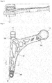
FIG. 1 is a perspective view illustrating a suspension arm for a vehicle according to one embodiment of the present disclosure. -
FIG. 2 is a plan view illustrating only an arm body in the suspension arm for a vehicle shown inFIG. 1 . -
FIG. 3 is a cross-sectional view taken along line A-A ofFIG. 2 . -
FIG. 4 is a plan view illustrating the suspension arm for a vehicle shown inFIG. 1 . -
FIG. 5 is a cross-sectional view taken along line C-C ofFIG. 4 . -
FIG. 6 is an enlarged view illustrating a coupling portion of the arm body and a plastic insert molding part according to one embodiment of the present disclosure. -
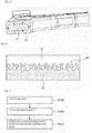
FIG. 7 is a flowchart illustrating a method of manufacturing a suspension arm for a vehicle according to one embodiment of the present disclosure. -
FIG. 8 is a flowchart illustrating a method of manufacturing a suspension arm for a vehicle according to another embodiment of the present disclosure. -
FIG. 9 is a flowchart illustrating a method of manufacturing a suspension arm for a vehicle according to still another embodiment of the present disclosure. - Embodiments of the present disclosure are exemplified for the purpose of describing the technical spirit of the present disclosure. The scope of the claims according to the present disclosure is not limited to the embodiments described below or to the detailed descriptions of these embodiments.
- Unless otherwise defined, all technical and scientific terms used herein have the same meaning commonly understood by those skilled in the art to which the present disclosure pertains. All terms used herein are selected for the purpose of more clearly describing the present disclosure and not limiting the scope of the present disclosure defined by appended claims.
- Unless the phrase or sentence clearly indicates otherwise, terms "comprising," "including," " having," "taking," and the like used herein should be construed as openended terms encompassing the possibility of including other embodiments.
- The singular form described herein may include the plural form unless the context clearly dictates otherwise, and this is equally applied to the singular form set forth in the claims.
- Terms a "first," a "second," and the like are used to distinguish a plurality of components, and the order or importance of corresponding components is not limited by these terms.
- Hereinafter, exemplary embodiments of the present disclosure will be described with reference to the accompanying drawings. In the accompanying drawings, the same reference numerals are assigned to the same or corresponding components. Further, in the following description of the embodiments, a duplicate description of the same or corresponding components may be omitted. However, even though a description of a component is omitted, such a component is not intended to be excluded in any embodiment. Further, exemplary embodiments of a hybrid suspension arm for a vehicle, which will be described below, may be used as an upper control arm or a lower control arm in a vehicle suspension system.
- Further, in a suspension arm for a vehicle according to the present disclosure and a manufacturing method therefor, the following description is made with respect to examples of a lower control arm, but the present disclosure is not limited thereto, and this description is also applicable to an upper control arm.
-
FIG. 1 is a perspective view illustrating a suspension arm 1 for a vehicle according to one embodiment of the present disclosure, andFIG. 2 is a plan view illustrating anarm body 10 constituting the suspension arm 1. - For example, the
arm body 10 may have a "λ" shape. Thearm body 10 may be manufactured by casting or die casting a material comprising aluminum. - The
arm body 10 may have a truss structure. The truss structure defined herein means a structure formed of a plurality of straight bars and/or curved bars. - Referring to
FIG. 2 , when viewed from a top of the suspension arm for a vehicle, the truss structure of thearm body 10 may comprises a structure comprising at least oneouter frame 101 forming thearm body 10, at least onecircular frame 103 disposed inside the outer frame, at least onestraight frame 102 connecting between theouter frames 101 and between theouter frame 101 and thecircular frame 103. - As the
arm body 10 according to the present disclosure is manufactured using aluminum through casting or die casting, it is possible to manufacture thearm body 10 in a truss structure which is difficult to be formed by conventional press forming process. Consequently, when compared with a conventional "⊏"-shaped steel arm body, it is possible for thearm body 10 to obtain required strength while reducing a weight thereof. - Further, the strength of the
arm body 10 according to the present disclosure may be further improved due to a configuration which will be described below. - For example, a thickness of the portion in which at least two among the
outer frames 101, thecircular frame 103, and thestraight frames 102 of thearm body 10 are connected may be formed to be greater than a thickness of the straight frame. Further, theouter frame 101 may include curved portion and straight portion, and thecircular frame 103 is curved. According to the present embodiment, a thickness of at least a portion of the curved portion is formed to be greater than a thickness of the straight portion such that a portion vulnerable to buckling deformation may be complemented and rigidity may be increased. - Further, as shown in
FIGS. 4 and5 , in order to enhance strength without significantly increasing a weight, the suspension arm 1 may comprise aninsert molding part 20 made of plastic material, which is insert-molded on an outer side of thearm body 10 and coupled thereon. In one embodiment of the present disclosure, the plasticinsert molding part 20 is formed of fiber-reinforced plastic material. Specifically, the plasticinsert molding part 20 may be formed of polyamide resin such as nylon 6 (PA6), nylon 66 (PA66), or the like, or polyamide resin in which glass fiber is contained in nylon 6, nylon 66, or the like. -
FIG. 4 is a plan view illustrating the suspension arm for a vehicle shown inFIG. 1 , andFIG. 5 is a cross-sectional view taken along line C-C ofFIG. 4 . - As shown in
FIG. 5 , the plasticinsert molding part 20 may be formed to surround thearm body 10. Since plastic material has a shrinkage rate that is greater than that of steel material, in the conventional case, when cooling is performed after insert molding, a plastic insert molding part coupled to an inner side of an arm body made of steel material shrinks more than the arm body and is separated from the arm body. Consequently, there is a problem in the conventional suspension arm that the plastic insert molding part cannot be firmly coupled to the arm body such and overall strength of the suspension arm is degraded. In the suspension arm according to one embodiment of the present disclosure, since the plasticinsert molding part 20 surrounds thearm body 10, when cooling is performed after insert molding, the plasticinsert molding part 20 shrinks toward thearm body 10 disposed therein in an arrow direction shown inFIG. 5 . Therefore, a gap does not occur in aportion 200 between thearm body 10 and the plasticinsert molding part 20, and the plasticinsert molding part 20 is firmly coupled to thearm body 10. - Further, as shown in
FIG. 6 (which is an enlarged view of a coupling portion of the arm body and the plastic insert molding part), a surface treatment may be performed on thearm body 10 to form a plurality of irregularities thereon. When viewed from a top of thearm body 10, the irregularities may be formed of a plurality of holes having an average diameter in a range of 1 µm to 100 µm. The plurality of holes may be formed using anodization coating in which an oxide film is formed on a surface of metal material with oxygen generated by applying electricity in an electrolytic solution, and a desired level of a porous surface may be obtained on a surface of metal material by changing an electrolytic solution and electric conditions (a current density, a voltage, a frequency, and the like). The plurality of irregularities formed on the surface of thesuspension arm body 10 increase a coupling area between thearm body 10 and the plasticinsert molding part 20, thereby increasing a coupling force therebetween. That is, probability in which a gap occurs between thearm body 10 and the plasticinsert molding part 20 is low, and even when a crack occurs in the plasticinsert molding part 20, probability in which the plasticinsert molding part 20 is separated from thearm body 10 is low. - Furthermore, since the
arm body 10 according to one embodiment of the present disclosure is manufactured using aluminum through casting or die casting, when compared with a conventional arm body formed by pressing and bending steel material, matching property between thearm body 10 and a mold (for insert molding) is improved. Consequently, when insert molding is performed, it is prevented that the plasticinsert molding part 20 is improperly formed on a portion of thearm body 10 or a burr is formed. - Further, when a gap is formed between the
arm body 10 and the plasticinsert molding part 20, rainwater and the like may penetrate into the gap and thearm body 10 may be corroded. In thearm body 10 according to one embodiment of the present disclosure, the plasticinsert molding part 20 is firmly coupled to thearm body 10 to minimize the gap such that corrosion of thearm body 10 is prevented and durability of the suspension arm 1 is enhanced. - Returning back to
FIG. 2 , thearm body 10 may comprise three end portions, and a balljoint coupling part 30 may be integrally formed on at least one end portion among the three end portions. Further, abush coupling part 40 may be integrally formed on at least one end portion of thearm body 10. As described above, since thearm body 10 may be manufactured using aluminum through casting or die casting, the balljoint coupling part 30 and thebush coupling part 40 may be integrally formed through a single casting or die casting process. That is, since it is not necessary to form a separate ball joint coupling part and a separate bush coupling part and then weld the ball joint coupling part and the bush coupling part to the arm body, a manufacturing process may be simplified. - A ball joint 31 may be coupled to the ball
joint coupling part 30, and the ball joint 31 may be coupled to a vehicle wheel. Further, abush 41 may be coupled to thebush coupling part 40, and the bush may be engaged with a vehicle body through a bolt or the like. - The plastic
insert molding part 20 may not be formed on the balljoint coupling part 30 and thebush coupling part 40. The balljoint coupling part 30 and thebush coupling part 30, which are formed of aluminum material, has excellent corrosion resistance, and thus a separate coating treatment may not be necessarily required. - Next, a method of manufacturing a suspension arm according to one embodiment of the present disclosure will be described with reference to
FIG. 7 . As shown inFIG. 7 , the method of manufacturing a suspension arm according to one embodiment of the present disclosure may comprise preparing an arm body (ST100), placing the arm body on a mold (ST200), and forming a plastic insert molding part by insert-molding plastic material into the mold (ST300). - In the preparing of the arm body 10 (ST100), aluminum material may be formed to correspond to a predetermined shape of the
arm body 10 by casting or die casting. - When the preparing of the arm body 10 (ST100) is completed, the placing of the
prepared arm body 10 on the mold (ST200) is performed. In operation ST200, in order to fix a position of thearm body 10 in the mold, a portion of thearm body 10 may be brought into contact with the mold to be fixed thereto. For example, the portions which are not covered with the plasticinsert molding part 20, i.e., theportion 300 which theouter frame 101 is brought into contact with the balljoint coupling part 30 and thebush coupling part 40 in thearm body 10, may be placed to be brought into direct contact with the mold. - In the forming of the plastic insert molding part by insert molding plastic material into the mold (ST300), heated plastic is injected into the mold so that the plastic
insert molding part 20 is formed to surround thearm body 10. - As shown in
FIG. 8 , according to one embodiment for manufacturing the suspension arm 1 of the present disclosure, before the placing of thearm body 10 on the mold (ST200), a surface treatment may be performed on thearm body 10 to form a plurality of irregularities thereon. For example, holes, each having a size in a range of 1 to 100 µm, are formed on a surface of thearm body 10 such that an area in which the plasticinsert molding part 20 is brought into contact with thearm body 10 is increased, and thus the coupling force between different materials may be improved (in the subsequent plastic insert molding process). - As shown in
FIG. 9 , according to one embodiment for manufacturing the suspension arm 1 of the present disclosure, before the placing of thearm body 10 on the mold (ST200), the manufacturing method may further comprise additionally machining theportion 300 in which thearm body 10 is brought into contact with the mold. In the preparing of thearm body 10, when theportion 300 of the arm body which should be brought into contact with the mold is formed with a tolerance that is larger than a dimension of a corresponding part of the mold, injection molding material leaks from the mold during injection molding process such that a burr occurs or a portion in which the insert molding is not formed occurs. When the matching property between thearm body 10 and the mold is insufficient, theportion 300 of thearm body 10 is machined using a milling machine, a lathe, a numerical control (NC) type machining tool, or the like so as to match the dimension of theportion 300 to the dimension of the corresponding part of the mold. Consequently, the matching property between thearm body 10 and the mold can be enhanced and it is possible to suppress occurrence of the portion in which the insert molding part is not formed or occurrence of a burr. - As described above, although the exemplary embodiments have been described with reference to the accompanying drawings, various alternations and modifications can be derived by those skilled in the art from the above description of the present disclosure. For example, it should be understood that an appropriate result may be achieved even when the techniques described herein may be performed in a different order than the described methods, and/or that components of the described structures, devices, and the like are coupled or combined in a form different from the described methods, or substituted or replaced with other components or equivalents.
Claims (15)
- A hybrid suspension arm for a vehicle, comprising:an arm body comprising aluminum; andan insert molding part made of plastic material, which is insert-molded on the arm body and coupled thereto.
- The hybrid suspension arm according to Claim 1, wherein the arm body has a truss structure.
- The hybrid suspension arm according to Claim 1, wherein, when viewed from a cross section of the suspension arm, the arm body is surrounded by the insert molding part.
- The hybrid suspension arm according to Claim 1, wherein the arm body comprises curved portion and straight portion, and a thickness of at least a portion of the curved portion is greater than a thickness of the straight portion.
- The hybrid suspension arm according to Claim 1, wherein a ball joint coupling part is integrally formed on at least one end portion of the arm body.
- The hybrid suspension arm according to Claim 1, wherein a bush coupling part is integrally formed on at least one end portion of the arm body.
- The hybrid suspension arm according to Claim 1, wherein a surface treatment is performed on the arm body to form a plurality of irregularities thereon.
- The hybrid suspension arm according to Claim 2, wherein, when viewed from a top of the arm body 10, the irregularities are formed of a plurality of holes having an average diameter in a range of 1µm to 100µm.
- The hybrid suspension arm according to Claim 1, wherein the insert molding part made of plastic material is formed of nylon-based resin.
- The hybrid suspension arm according to Claim 2, wherein the arm body comprise at least one outer frame for forming the arm body, at least one circular frame disposed inside the outer frame, and at least one straight frame for connecting between the outer frames and between the outer frame and the circular frame, so as to have the truss structure.
- The hybrid suspension arm according to Claim 10, wherein a thickness of the portion in which at least two among the outer frame, the circular frame, and the straight frame are connected is greater than a thickness of the straight frame.
- A method of manufacturing a hybrid suspension arm for a vehicle, the method comprising:preparing an arm body comprising aluminum;placing the arm body on a mold; andforming an insert molding part coupled to the arm body by insert-molding plastic material into the mold.
- The method according to Claim 12, further comprising:
performing a surface treatment on the arm body to form a plurality of irregularities thereon. - The method according to Claim 12, further comprising;
machining the portion of the arm body, which is brought into contact with the mold, so as to match a dimension of the portion of the arm body to that of the mold. - The method according to Claim 12, wherein the preparing of the arm body comprises forming the arm body by casting or die casting.
Applications Claiming Priority (2)
| Application Number | Priority Date | Filing Date | Title |
|---|---|---|---|
| KR1020160181227A KR101857172B1 (en) | 2016-12-28 | 2016-12-28 | Hybrid suspension arm for vehicle and manufacturing method thereof |
| PCT/KR2017/015138 WO2018124609A1 (en) | 2016-12-28 | 2017-12-20 | Hybrid suspension arm for vehicle and method for manufacturing same |
Publications (2)
| Publication Number | Publication Date |
|---|---|
| EP3564053A1 true EP3564053A1 (en) | 2019-11-06 |
| EP3564053A4 EP3564053A4 (en) | 2020-09-23 |
Family
ID=62452073
Family Applications (1)
| Application Number | Title | Priority Date | Filing Date |
|---|---|---|---|
| EP17887512.6A Withdrawn EP3564053A4 (en) | 2016-12-28 | 2017-12-20 | HYBRID SUSPENSION ARM FOR VEHICLE AND METHOD OF MANUFACTURING THEREOF |
Country Status (4)
| Country | Link |
|---|---|
| US (1) | US20190315174A1 (en) |
| EP (1) | EP3564053A4 (en) |
| KR (1) | KR101857172B1 (en) |
| WO (1) | WO2018124609A1 (en) |
Cited By (1)
| Publication number | Priority date | Publication date | Assignee | Title |
|---|---|---|---|---|
| EP3936354A1 (en) * | 2020-07-08 | 2022-01-12 | Autotech Engineering S.L. | Chassis component for a motor vehicle, in particular transverse arm, and method for manufacturing such a chassis component |
Families Citing this family (18)
| Publication number | Priority date | Publication date | Assignee | Title |
|---|---|---|---|---|
| WO2017115932A1 (en) * | 2015-12-30 | 2017-07-06 | 주식회사 일진 | Hybrid suspension arm for vehicle and manufacturing method therefor |
| KR20200047193A (en) * | 2018-10-26 | 2020-05-07 | 주식회사 일진 | Insert device for manufacturing hybrid arm and hybrid arm comprising same |
| DE102019200456A1 (en) * | 2019-01-16 | 2020-07-16 | Zf Friedrichshafen Ag | Chassis component for the articulated connection of components in a chassis of a vehicle and method for producing such a chassis component |
| USD905798S1 (en) * | 2019-06-27 | 2020-12-22 | Traxxas Lp | Model vehicle upper suspension arm |
| USD905799S1 (en) * | 2019-06-27 | 2020-12-22 | Traxxas Lp | Model vehicle lower suspension arm |
| USD951149S1 (en) | 2019-10-31 | 2022-05-10 | Traxxas, L.P. | Model vehicle upper suspension arm |
| USD951148S1 (en) | 2019-10-31 | 2022-05-10 | Traxxas, L.P. | Model vehicle lower suspension arm |
| USD951151S1 (en) | 2019-10-31 | 2022-05-10 | Traxxas, L.P. | Model vehicle lower suspension arm |
| USD951150S1 (en) | 2019-10-31 | 2022-05-10 | Traxxas, L.P. | Model vehicle lower suspension arm |
| USD944901S1 (en) | 2019-12-06 | 2022-03-01 | Traxxas Lp | Model vehicle lower suspension arm |
| USD947957S1 (en) | 2019-12-11 | 2022-04-05 | Traxxas Lp | Model vehicle upper suspension arm |
| FR3113380B1 (en) * | 2020-08-12 | 2022-12-30 | Conseil & Technique | Process for manufacturing a mechanical part, the part obtained and a suspension wishbone. |
| KR102756537B1 (en) * | 2020-10-06 | 2025-01-20 | 현대모비스 주식회사 | Suspension system for vehicle with leaf spring |
| JP7140868B1 (en) * | 2021-03-22 | 2022-09-21 | 本田技研工業株式会社 | Manufacturing method of trailing arm |
| USD1014655S1 (en) | 2021-11-16 | 2024-02-13 | Traxxas, L.P. | Model vehicle suspension arm |
| USD1014656S1 (en) | 2021-11-16 | 2024-02-13 | Traxxas, L.P. | Model vehicle suspension arm |
| JP2025074848A (en) * | 2023-10-30 | 2025-05-14 | トヨタ自動車株式会社 | Suspension structure components |
| CN118527956B (en) * | 2024-05-15 | 2026-04-28 | 北京理工大学 | A method for manufacturing a steel-aluminum composite material vehicle suspension control arm |
Family Cites Families (10)
| Publication number | Priority date | Publication date | Assignee | Title |
|---|---|---|---|---|
| DE19961425B4 (en) * | 1999-12-17 | 2005-10-20 | Zf Lemfoerder Metallwaren Ag | Motor vehicle component |
| DE102005004917B4 (en) * | 2005-02-02 | 2013-02-28 | Benteler Automobiltechnik Gmbh | Handlebar component for wheel suspensions of motor vehicles and method for its production |
| DE102007015616B4 (en) * | 2007-03-29 | 2021-10-21 | Zf Friedrichshafen Ag | Connector for the articulated connection of components arranged in the chassis of a vehicle |
| KR20100116081A (en) * | 2009-04-21 | 2010-10-29 | 주식회사 일진 | Control arm of vehicle and manufacturing method thereof |
| KR20110063165A (en) * | 2009-12-04 | 2011-06-10 | 현대자동차주식회사 | How to Build Suspension Arms and Suspension Arms |
| FR2993806B1 (en) * | 2012-07-26 | 2015-02-13 | Saint Jean Ind | PROCESS FOR MANUFACTURING STRUCTURE PARTS OF LIGHT ALLOY AND PARTS THUS OBTAINED FOR OPTIMIZING THE MASS / PERFORMANCE RATIO |
| JP5798535B2 (en) * | 2012-09-07 | 2015-10-21 | ダイセルポリマー株式会社 | Method for producing composite molded body |
| KR101393849B1 (en) * | 2012-12-12 | 2014-05-12 | 현대자동차주식회사 | Law arm for vehicle |
| DE102015202085A1 (en) * | 2015-02-05 | 2016-08-11 | Volkswagen Aktiengesellschaft | Suspension component in hybrid construction |
| DE102015204643A1 (en) * | 2015-03-13 | 2016-09-15 | Volkswagen Aktiengesellschaft | Cast control arm for a motor vehicle |
-
2016
- 2016-12-28 KR KR1020160181227A patent/KR101857172B1/en not_active Expired - Fee Related
-
2017
- 2017-12-20 WO PCT/KR2017/015138 patent/WO2018124609A1/en not_active Ceased
- 2017-12-20 EP EP17887512.6A patent/EP3564053A4/en not_active Withdrawn
-
2019
- 2019-06-27 US US16/454,897 patent/US20190315174A1/en not_active Abandoned
Cited By (1)
| Publication number | Priority date | Publication date | Assignee | Title |
|---|---|---|---|---|
| EP3936354A1 (en) * | 2020-07-08 | 2022-01-12 | Autotech Engineering S.L. | Chassis component for a motor vehicle, in particular transverse arm, and method for manufacturing such a chassis component |
Also Published As
| Publication number | Publication date |
|---|---|
| KR101857172B1 (en) | 2018-05-16 |
| EP3564053A4 (en) | 2020-09-23 |
| WO2018124609A1 (en) | 2018-07-05 |
| US20190315174A1 (en) | 2019-10-17 |
Similar Documents
| Publication | Publication Date | Title |
|---|---|---|
| EP3564053A1 (en) | Hybrid suspension arm for vehicle and method for manufacturing same | |
| JP5523164B2 (en) | Electrode terminal and method for manufacturing electrode terminal | |
| US10059089B2 (en) | Metal or ceramic component comprising at least one multi-dimensionally structured connection portion and method for the production thereof | |
| EP3564052A1 (en) | Hybrid suspension arm for vehicle | |
| US20160318097A1 (en) | Cast-in structure and cast-in mold for vehicle component | |
| KR20130080041A (en) | Electrically conductive connecting member, process for manufacturing electrically conductive connecting member, and battery equipped with electrically conductive connecting member as electrode | |
| US20100043742A1 (en) | Method and electrode for the production of a radial bearing surface, and connecting rod | |
| KR20160056800A (en) | Fuel cell end plate, method of manufacturing same, and fuel cell | |
| CN109996635B (en) | Component with a joining aid, component assembly of at least two components and method for producing the same | |
| WO2017027087A1 (en) | Trailing edge components, aircraft structures including trailing edge components and methods for manufacturing trailing edge components | |
| US20180021890A1 (en) | System and method to produce a structure for a weld joint using additive manufacturing | |
| EP2578351A1 (en) | Driver's cab of magnetically levitated train and manufacturing method thereof | |
| EP3666626A1 (en) | Vehicle knuckle and method for manufacturing same | |
| KR20190005754A (en) | Method for producing a bearing bush, bearing bush and control arm for a wheel suspension of a motor vehicle | |
| CN114899567B (en) | Processing method of flange type waveguide | |
| CN114535935A (en) | Metal edge sealing of fan blade and processing method thereof | |
| CN112619986B (en) | Die sleeve, split type special-shaped painting die with die sleeve and painting threading method | |
| CN112078146B (en) | Method for winding front skirt and rear skirt of engine shell by fibers | |
| JP2006316834A (en) | Manufacturing method of pressure vessel liner | |
| CN211731014U (en) | Suspension bracket assembly of electric passenger car | |
| CN110039215B (en) | Preparation method and welding structure of precision gap sample | |
| CN108568575B (en) | Nut cover die processing method and nut cover die | |
| CN118060396B (en) | Battery pole forming method | |
| CN110153645B (en) | Method for processing tiller | |
| US20260088411A1 (en) | Hybrid metal/composite battery tray |
Legal Events
| Date | Code | Title | Description |
|---|---|---|---|
| STAA | Information on the status of an ep patent application or granted ep patent |
Free format text: STATUS: THE INTERNATIONAL PUBLICATION HAS BEEN MADE |
|
| PUAI | Public reference made under article 153(3) epc to a published international application that has entered the european phase |
Free format text: ORIGINAL CODE: 0009012 |
|
| STAA | Information on the status of an ep patent application or granted ep patent |
Free format text: STATUS: REQUEST FOR EXAMINATION WAS MADE |
|
| 17P | Request for examination filed |
Effective date: 20190718 |
|
| AK | Designated contracting states |
Kind code of ref document: A1 Designated state(s): AL AT BE BG CH CY CZ DE DK EE ES FI FR GB GR HR HU IE IS IT LI LT LU LV MC MK MT NL NO PL PT RO RS SE SI SK SM TR |
|
| AX | Request for extension of the european patent |
Extension state: BA ME |
|
| DAV | Request for validation of the european patent (deleted) | ||
| DAX | Request for extension of the european patent (deleted) | ||
| A4 | Supplementary search report drawn up and despatched |
Effective date: 20200825 |
|
| RIC1 | Information provided on ipc code assigned before grant |
Ipc: B60G 7/00 20060101AFI20200819BHEP Ipc: B29C 45/14 20060101ALI20200819BHEP |
|
| STAA | Information on the status of an ep patent application or granted ep patent |
Free format text: STATUS: EXAMINATION IS IN PROGRESS |
|
| 17Q | First examination report despatched |
Effective date: 20210414 |
|
| STAA | Information on the status of an ep patent application or granted ep patent |
Free format text: STATUS: THE APPLICATION IS DEEMED TO BE WITHDRAWN |
|
| 18D | Application deemed to be withdrawn |
Effective date: 20211026 |