EP3933141B1 - Procédé pour la fabrication d'un élément en béton préfabriqué - Google Patents
Procédé pour la fabrication d'un élément en béton préfabriqué Download PDFInfo
- Publication number
- EP3933141B1 EP3933141B1 EP20183120.3A EP20183120A EP3933141B1 EP 3933141 B1 EP3933141 B1 EP 3933141B1 EP 20183120 A EP20183120 A EP 20183120A EP 3933141 B1 EP3933141 B1 EP 3933141B1
- Authority
- EP
- European Patent Office
- Prior art keywords
- lifting
- sleeve
- component
- precast concrete
- chamber
- Prior art date
- Legal status (The legal status is an assumption and is not a legal conclusion. Google has not performed a legal analysis and makes no representation as to the accuracy of the status listed.)
- Active
Links
- 238000000034 method Methods 0.000 title claims description 24
- 238000004519 manufacturing process Methods 0.000 title claims description 21
- 239000011178 precast concrete Substances 0.000 title description 90
- 238000004873 anchoring Methods 0.000 claims description 38
- 239000004567 concrete Substances 0.000 claims description 29
- 238000009415 formwork Methods 0.000 claims description 28
- 238000009434 installation Methods 0.000 claims description 3
- 238000003780 insertion Methods 0.000 description 14
- 230000037431 insertion Effects 0.000 description 14
- 239000000758 substrate Substances 0.000 description 5
- 229910000831 Steel Inorganic materials 0.000 description 4
- 239000010959 steel Substances 0.000 description 4
- 239000002184 metal Substances 0.000 description 3
- 230000008901 benefit Effects 0.000 description 2
- 239000011148 porous material Substances 0.000 description 2
- 206010015535 Euphoric mood Diseases 0.000 description 1
- 238000010276 construction Methods 0.000 description 1
- 230000006872 improvement Effects 0.000 description 1
- 230000003993 interaction Effects 0.000 description 1
- 239000000463 material Substances 0.000 description 1
- 230000008569 process Effects 0.000 description 1
- 239000011435 rock Substances 0.000 description 1
- 238000009416 shuttering Methods 0.000 description 1
Images

Classifications
-
- E—FIXED CONSTRUCTIONS
- E04—BUILDING
- E04G—SCAFFOLDING; FORMS; SHUTTERING; BUILDING IMPLEMENTS OR AIDS, OR THEIR USE; HANDLING BUILDING MATERIALS ON THE SITE; REPAIRING, BREAKING-UP OR OTHER WORK ON EXISTING BUILDINGS
- E04G21/00—Preparing, conveying, or working-up building materials or building elements in situ; Other devices or measures for constructional work
- E04G21/14—Conveying or assembling building elements
- E04G21/142—Means in or on the elements for connecting same to handling apparatus
-
- B—PERFORMING OPERATIONS; TRANSPORTING
- B28—WORKING CEMENT, CLAY, OR STONE
- B28B—SHAPING CLAY OR OTHER CERAMIC COMPOSITIONS; SHAPING SLAG; SHAPING MIXTURES CONTAINING CEMENTITIOUS MATERIAL, e.g. PLASTER
- B28B23/00—Arrangements specially adapted for the production of shaped articles with elements wholly or partly embedded in the moulding material; Production of reinforced objects
- B28B23/005—Arrangements specially adapted for the production of shaped articles with elements wholly or partly embedded in the moulding material; Production of reinforced objects with anchoring or fastening elements for the shaped articles
-
- B—PERFORMING OPERATIONS; TRANSPORTING
- B66—HOISTING; LIFTING; HAULING
- B66C—CRANES; LOAD-ENGAGING ELEMENTS OR DEVICES FOR CRANES, CAPSTANS, WINCHES, OR TACKLES
- B66C1/00—Load-engaging elements or devices attached to lifting or lowering gear of cranes or adapted for connection therewith for transmitting lifting forces to articles or groups of articles
- B66C1/10—Load-engaging elements or devices attached to lifting or lowering gear of cranes or adapted for connection therewith for transmitting lifting forces to articles or groups of articles by mechanical means
- B66C1/62—Load-engaging elements or devices attached to lifting or lowering gear of cranes or adapted for connection therewith for transmitting lifting forces to articles or groups of articles by mechanical means comprising article-engaging members of a shape complementary to that of the articles to be handled
- B66C1/66—Load-engaging elements or devices attached to lifting or lowering gear of cranes or adapted for connection therewith for transmitting lifting forces to articles or groups of articles by mechanical means comprising article-engaging members of a shape complementary to that of the articles to be handled for engaging holes, recesses, or abutments on articles specially provided for facilitating handling thereof
- B66C1/666—Load-engaging elements or devices attached to lifting or lowering gear of cranes or adapted for connection therewith for transmitting lifting forces to articles or groups of articles by mechanical means comprising article-engaging members of a shape complementary to that of the articles to be handled for engaging holes, recesses, or abutments on articles specially provided for facilitating handling thereof for connection to anchor inserts embedded in concrete structures
-
- E—FIXED CONSTRUCTIONS
- E01—CONSTRUCTION OF ROADS, RAILWAYS, OR BRIDGES
- E01C—CONSTRUCTION OF, OR SURFACES FOR, ROADS, SPORTS GROUNDS, OR THE LIKE; MACHINES OR AUXILIARY TOOLS FOR CONSTRUCTION OR REPAIR
- E01C5/00—Pavings made of prefabricated single units
- E01C5/005—Individual couplings or spacer elements for joining the prefabricated units
-
- E—FIXED CONSTRUCTIONS
- E01—CONSTRUCTION OF ROADS, RAILWAYS, OR BRIDGES
- E01C—CONSTRUCTION OF, OR SURFACES FOR, ROADS, SPORTS GROUNDS, OR THE LIKE; MACHINES OR AUXILIARY TOOLS FOR CONSTRUCTION OR REPAIR
- E01C5/00—Pavings made of prefabricated single units
- E01C5/06—Pavings made of prefabricated single units made of units with cement or like binders
-
- E—FIXED CONSTRUCTIONS
- E04—BUILDING
- E04B—GENERAL BUILDING CONSTRUCTIONS; WALLS, e.g. PARTITIONS; ROOFS; FLOORS; CEILINGS; INSULATION OR OTHER PROTECTION OF BUILDINGS
- E04B5/00—Floors; Floor construction with regard to insulation; Connections specially adapted therefor
- E04B5/02—Load-carrying floor structures formed substantially of prefabricated units
- E04B5/04—Load-carrying floor structures formed substantially of prefabricated units with beams or slabs of concrete or other stone-like material, e.g. asbestos cement
-
- E—FIXED CONSTRUCTIONS
- E04—BUILDING
- E04G—SCAFFOLDING; FORMS; SHUTTERING; BUILDING IMPLEMENTS OR AIDS, OR THEIR USE; HANDLING BUILDING MATERIALS ON THE SITE; REPAIRING, BREAKING-UP OR OTHER WORK ON EXISTING BUILDINGS
- E04G15/00—Forms or shutterings for making openings, cavities, slits, or channels
- E04G15/04—Cores for anchor holes or the like around anchors embedded in the concrete
Definitions
- the invention relates to a method for producing a precast concrete component, in particular a precast concrete slab, the component being manufactured in formwork and at least one lifting sleeve being introduced into the component during manufacture.
- the precast concrete components or precast concrete slabs are used in particular as subsoil or trafficable subsoil for storage areas, parking and storage areas, for areas in the construction industry, for roads and the like.
- Precast concrete components or precast concrete slabs of the type described above are basically known in different embodiments from practice. Especially with large-area precast concrete components or precast concrete slabs, both the transport and the handling and assembly at the installation site are often a challenge. In this connection it is known to provide transport anchors which are integrated into the precast concrete components and which can be fixed to a transport device such as a crane. In addition, it is known from practice to handle precast concrete components using vacuum lifting devices. This handling with vacuum lifting devices can be used both in the course of the assembly of the precast concrete components or precast concrete slabs and also during production when the precast concrete components have to be lifted out of a formwork, for example.
- precast concrete components or precast concrete slabs are not suitable for all types of precast concrete components or precast concrete slabs.
- vacuum lifting devices are used in precast concrete components or ready-made concrete slabs made of open-pored concrete cannot be used reliably, since the open-pored structure means that no secure fixation can be achieved.
- JP 2003-112884 A describes a concrete component with a lifting sleeve.
- the component can be fixed to a transport device by means of the lifting sleeve.
- the lifting sleeve has a lifting chamber whose inner diameter is larger than the inner width of the sleeve shank.
- a cap provided on the lower sleeve opening is removed, resulting in a downward drainage opening.
- the invention is based on the technical problem of specifying a method for producing a precast concrete component, in particular a precast concrete slab, in which the component or the slab can be handled reliably and trouble-free and, in particular, can be fixed securely and reliably to a transport device.
- the invention is based on the finding that the method according to the invention with the lifting sleeve concreted into the precast concrete component functionally reliable and easy handling of the precast concrete component or the precast concrete slab and in particular the reliable fixation on a transport device. This applies both to the production, in particular to the shuttering of the precast concrete component, and to the assembly.
- the handling of the precast concrete component or the precast concrete slab, in particular the fixing to a transport device is carried out with the help of the lifting key, which is inserted into the sleeve shaft of the lifting sleeve and in the at least one lifting chamber and optionally also on the top side of the precast concrete component or precast concrete component underside can be transferred from an insertion position into an anchoring position.
- the lifting key which is inserted into the sleeve shaft of the lifting sleeve and in the at least one lifting chamber and optionally also on the top side of the precast concrete component or precast concrete component underside can be transferred from an insertion position into an anchoring position.
- inner diameter d K of the lifting chamber means in particular the largest inner diameter of the lifting chamber transversely, in particular perpendicular to the longitudinal extent or to the longitudinal axis A of the lifting sleeve.
- inner width bs of the sleeve shank means in particular the largest inner width of the sleeve shank transversely, in particular perpendicular to the longitudinal extension or to the longitudinal axis A of the lifting sleeve or the sleeve shank and transversely, in particular perpendicular to the longitudinal center axis A Q of the cross-sectional area of the sleeve shank.
- the ratio of the inner diameter d K of the lifting chamber to the inner width bs of the sleeve shaft is between 1.1:1 and 4:1, preferably between 1.5:1 and 3:1, preferably between 1.7: 1 and 2.2:1, most preferably between 1.9:1 and 2.1:1, for example about 2:1.
- a component or a panel has two to six lifting sleeves, preferably two to four lifting sleeves and particularly preferably two lifting sleeves, which are embedded in concrete in the component or in the panel.
- the embodiment with at least two lifting sleeves is based on the finding that the component or the plate can be fixed particularly reliably and securely to a transport device by at least two lifting sleeves embedded in concrete.
- the lifting sleeve is hollow on the inside at least in regions and is preferably hollow on the inside over its entire length L or essentially over its entire length L.
- the lifting sleeve is therefore recommended to have a cavity which extends in the direction of the longitudinal axis A of the lifting sleeve over its entire length.
- the diameter of the cavity is expediently at least 70%, preferably at least 75%, very preferably at least 80% and particularly preferably at least 85% of the outer diameter of the lifting sleeve.
- the lifting sleeve is embedded in concrete over its entire length L or essentially over its entire length L in the component.
- length L of the lifting sleeve means in particular the greatest extension of the lifting sleeve along or in the direction of its longitudinal axis A.
- the first sleeve opening is associated with the underside of the component or panel and is accessible from the underside of the component or panel.
- underside of the component or panel means that side of the component or panel that faces the mounting substrate when the component or panel is in the installed state.
- the at least one lifting chamber is designed as a hollow-cylindrical section of the lifting sleeve, which in particular has a round, preferably circular, cross-section with the inside diameter dK .
- the cross section of the lifting chamber means in particular the cross section across, in particular perpendicular to the longitudinal axis A of the lifting sleeve. If, according to a particularly preferred embodiment, the lifting chamber is designed as a hollow-cylindrical section with a circular cross section, the inner diameter d K of the lifting chamber corresponds to the circle diameter or inner circle diameter of the cross-sectional area.
- This embodiment is based on the finding that the lifting key - through the first sleeve opening assigned to the underside of the component - is inserted into the sleeve shaft and is transferred in the hollow-cylindrical lifting chamber, for example by a rotary movement, from an insertion position to an anchoring position, so that the precast concrete component or The precast concrete slab can be fixed to a transport device using the lifting sleeve and the lifting key.
- the ratio of the length L H of the lifting chamber to the length L of the lifting sleeve is 1:12 to 1:4, preferably 1:10 to 1:6, preferably 1:9 to 1:7, for example 1:8 or is about 1:8.
- length L H of the lifting chamber means the greatest extension of the lifting chamber in the longitudinal direction of the lifting sleeve or in the direction of the longitudinal axis A of the lifting sleeve.
- the sleeve shank is designed as a hollow body, the inner length Ls of which is preferably greater than that inside width up to
- inner length Ls of the sleeve shank means in particular the greatest inner length across, in particular perpendicular to the longitudinal axis A of the lifting sleeve and along or in the direction of the longitudinal center axis A Q of the cross-sectional area of the sleeve shank and thus across, in particular perpendicular to the inner width bs of the sleeve shank.
- the ratio of the inner length Ls of the sleeve shank to the inner width bs of the sleeve shank is 1.1:1 to 4:1, preferably 1.5:1 to 3:1, preferably 1.7:1 to 2. 2:1, more preferably 1.9:1 to 2.1:1, for example about 2:1. It is preferred that the inner length Ls of the sleeve shank corresponds or essentially corresponds to the inner diameter d K of the lifting chamber.
- the sleeve shank is designed as a hollow body, the cross-sectional area of which is provided as a rounded rectangle.
- the sleeve shank is designed as a hollow body whose cross-sectional area is elliptical.
- other cross-sectional geometries for the sleeve shaft are also within the scope of the invention, for example an oval, rectangular, square, triangular or the same cross-sectional geometry. It is essential that the inner diameter d K of the lifting chamber is larger than the inner width bs of the sleeve shank.
- a particularly recommended embodiment of the invention is characterized in that the precast concrete component or a precast concrete slab is designed for a drivable subsoil, for example a drivable street, a drivable storage area, a drivable parking area, such as a parking deck or the like.
- the thickness of a precast concrete slab is recommended to be 50 to 300 mm, preferably 100 to 250 mm and especially preferably 160 to 200 mm. It is recommended that a lifting sleeve extends over at least 70%, preferably over at least 80%, preferably over at least 90% and very particularly preferably over at least 95% of the thickness of the precast concrete component or the precast concrete slab.
- a precast concrete slab is rectangular in plan view.
- the side lengths of such a rectangular plate can each be 600 to 3000 mm, preferably 800 to 2500 mm, particularly preferably 1000 to 2200 mm.
- the longitudinal axis A of the lifting sleeve is arranged transversely, in particular perpendicularly or essentially perpendicularly to the underside and/or the upper side of the component.
- the upper side of the component means that side of the component which faces away from the mounting base in the mounted state. It is therefore within the scope of the invention for the longitudinal axis A of the lifting sleeve to be oriented transversely, in particular perpendicularly or essentially perpendicularly, to the mounting base when the precast concrete component or the precast concrete slab is in the assembled state.
- the installation substrate means in particular the substrate or the ground on which the precast concrete component or the precast concrete slab is installed or laid.
- the lifting chamber is assigned to the end of the sleeve.
- the distance a between the lifting chamber and the sleeve end is between 2% and 49%, preferably between 5% and 40%, preferably between 7% and 35%, particularly preferably between 10% and 30% and very particularly preferably between 15% and 25% % of the length L of the lifting sleeve.
- Distance a between the stroke chamber and the sleeve end means the greatest distance between the lifting chamber and the end of the sleeve in the direction/along the longitudinal extent or the longitudinal axis A of the lifting sleeve, with the length L H of the lifting chamber itself counting for half of this distance a.
- the lifting key is inserted into the sleeve shaft from the underside of the component and transferred from the insertion position to an anchoring position in the lifting chamber assigned to the sleeve end, for example by a rotary movement.
- this anchoring position the precast concrete component or the precast concrete slab can be fixed to a transport device by means of the lifting key. This is particularly advantageous since the panel is removed from a formwork as part of its manufacture, with the top side of the panel facing the bottom of the formwork. The introduction of force during the lifting process of the component or the plate then takes place in the area of the plate opposite or facing away from the first sleeve opening.
- the lifting sleeve has at least two lifting chambers. Then preferably one of the lifting chambers is assigned to the sleeve end and/or a further lifting chamber is assigned to the first sleeve opening.
- the lifting sleeve has at least one anchoring rib, which runs around the outer circumference of the lifting sleeve by at least 70%, preferably by at least 80%, preferably completely or essentially completely. It is preferred that the lifting sleeve has at least two such anchoring ribs. Depending on the length L of the lifting sleeve and thus preferably also depending on the thickness of the precast concrete component or the precast concrete building slab, it is possible for the lifting sleeve to have a plurality of anchoring ribs, for example three to six anchoring ribs.
- the anchoring ribs enable the at least one lifting sleeve to be embedded in concrete in a particularly secure or firm manner the precast concrete component, which in particular also withstands larger forces, for example when the precast concrete component is fixed by means of the lifting sleeve by a lifting key located in the lifting chamber in an anchoring position on a transport device.
- the component or the precast concrete building slab is produced on the basis of at least one open-pore concrete and in particular consists or essentially consists of at least one open-pore concrete.
- Such an open-pored concrete is also referred to as no-fines concrete and expediently has cavities between the rock grains. It is preferred that the component, in particular the precast concrete slab, is water-permeable.
- the sleeve end is designed as a second sleeve opening, which is assigned to the upper side of the component and is accessible from the upper side of the component.
- the lift sleeve has a first sleeve opening associated with the bottom of the component and accessible from the bottom of the component and the lift sleeve further has a second sleeve opening associated with the top of the component and accessible from the top of the component.
- the lifting key is inserted through the first sleeve opening into the sleeve shaft and in the lifting chamber, for example by a rotary movement from the insertion position to a Anchoring position transferred. Then the precast concrete component or the precast concrete slab can be fixed to a transport device by means of the lifting sleeve and the lifting key located in the anchoring position and is lifted out of the formwork.
- the lifting key can then be inserted from the opposite side of the component, namely the upper side of the component, through the second sleeve opening into the sleeve shaft and passed completely through the lifting sleeve and then transferred to an anchoring position on the underside of the component or the slab by a rotary movement , so that the precast concrete component or the precast concrete slab can be installed or laid.
- the invention is thus based on the finding that the component or panel can be lifted out of the formwork by means of the lifting sleeve both during production of the component or panel and safely handled during assembly of the component or panel can be.
- the lifting sleeve of the component advantageously fulfills at least two functions.
- a lifting sleeve is used for embedding in concrete in a precast concrete component, in particular in a precast concrete slab - preferably in a precast concrete component of the type described above - the lifting sleeve having at least one first sleeve opening, at least one sleeve shaft for receiving a lifting key and one opposite the first sleeve opening Has sleeve end, wherein the lifting sleeve has at least one cross-sectional widening in the form of a lifting chamber, wherein the inner diameter d K of the lifting chamber is larger than the inner width bs of the sleeve shaft.
- the sleeve is made on the basis of at least one plastic and the lifting sleeve preferably consists of at least one plastic or essentially of at least one plastic.
- a system consisting of a lifting key and a lifting sleeve—in particular a lifting sleeve described above—is suitable for the method according to the invention, the lifting key having at least one anchor head and at least one guide rod, the anchor head being designed in such a way that it can be inserted into the lifting sleeve through a sleeve opening and in the lifting chamber and/or on the underside or top of the component by a rotary movement, preferably around the longitudinal axis of the lifting key or the guide rod, preferably around 10° to 90°, particularly preferably around 90°, from an insertion position in an anchoring position can be transferred.
- a fastening element is provided on the guide rod of the lifting key, expediently on the side opposite the anchor head, with which the lifting key can be fixed to a transport device.
- the fastening element can be, for example, a fastening eyelet.
- the shape of the anchor head of the lifting key is such that it can be inserted into the lifting sleeve through at least one sleeve opening and, in this insertion position, can be guided through the sleeve shank. It is recommended that the anchor head, in the insertion position in which it can be guided through the socket shank, not be rotatable in the socket shank or essentially not rotatable in the socket shank.
- the anchor head can then be transferred from the insertion position into an anchoring position, preferably by a rotary movement about the longitudinal axis of the lifting key or guide rod.
- the lifting key is rotated about its longitudinal axis and in particular by 10° to 90°, preferably by 45° to 90°, particularly preferably by 70° to 90°, very particularly preferably by about rotated 90°.
- the lifting key is formed on the basis of at least one metal and in particular consists of at least one metal.
- the lifting key consists of steel or essentially of steel.
- the lifting key is inserted through the first or second sleeve opening into the sleeve shank and is guided completely through the lifting sleeve to the opposite side of the component or panel and there is transferred into an anchoring position by a rotary movement about the longitudinal axis of the guide rod.
- the anchor ends of the anchor head expediently engage behind a surface of the lifting arm or the upper or lower side of the component or the plate.
- the manufacturing method according to the invention has proven itself in particular for components or precast concrete building panels made of porous concrete.
- the component side intended as the upper side of the component in the assembled or laid state faces the bottom of the formwork.
- the lifting chamber of the lifting sleeve is associated with the sleeve end, which is designed as the second sleeve opening.
- the second sleeve opening is associated with the top of the component and the lifting chamber is also associated with the top of the component.
- the lifting key is preferably fixed to a transport device
- the force is introduced into the component or the plate on the upper side of the Component provided component side and consequently on the bottom of the formwork side facing. In this way it is possible to remove the component or the plate from the formwork, even if the component or the plate is made of porous concrete according to the preferred embodiment and/or has not yet fully hardened.
- a subsurface, in particular a subsurface that can be driven on, can be realized with a plurality or a large number of ready-made concrete slabs arranged next to one another—for example 100 to 400 ready-made concrete slabs.
- Each of these precast concrete slabs can have at least two lifting sleeves embedded in concrete.
- Each precast concrete slab preferably occupies an area of 1 to 10 m 2 , preferably 2 to 6 m 2 .
- the precast concrete slabs are arranged in the desired positions to create the subsoil or the drivable subsoil by means of at least one transport device, for example by means of at least one transport crane, with the precast concrete slabs being lifted via their lifting sleeves and preferably via the system of a lifting key and a lifting sleeve are fixed to the transport device.
- the method preferably further includes the step of inserting the lift wrench through the second sleeve opening, which is the Top of the component is assigned to the sleeve shaft, the lifting key being guided completely through the sleeve shaft to the underside of the component, where it is converted into an anchoring position by a rotary movement about the longitudinal axis of the lifting key.
- the component is then expediently fixed in this anchoring position by means of the lifting key on a transport device and handled in this way.
- the lifting sleeve has at least two lifting chambers
- the lifting key can first be inserted from the underside of the component through a first sleeve opening into the sleeve shank of the lifting sleeve and can be transferred to an anchoring position in the first lifting chamber assigned to the top side of the component or the top of the plate .
- the precast concrete component or the precast concrete slab is then handled in this anchoring position by means of a transport device.
- the lifting key can be inserted into the sleeve shaft through a second sleeve opening, which is assigned to the upper side of the component, and transferred into an anchoring position in a second lifting chamber, preferably assigned to the underside of the component or plate.
- the component is then expediently fixed in the anchoring position by means of the lifting key on a transport device and handled in this way.
- the invention is based on the finding that the precast concrete component or the precast concrete slab can be functionally reliably and easily fixed to a transport device by means of the lifting sleeve.
- the fixation on a transport device is also possible in particular if, according to the preferred embodiment, an open-pored concrete is used as the material for the Precast concrete component or the precast concrete slab is used.
- the lifting sleeve has a first and a second sleeve opening, the sleeve is accessible from both sides of the component or the plate and it can be used in particular a simple and particularly advantageous handling of the component or the plate both in the context of the manufacture of the plate - for example the formwork - as well as during the assembly of the panel.
- a particular advantage of the invention is that one and the same lifting sleeve can be used both for removing the formwork from the component, during which a lifting key is transferred into an anchoring position in the lifting chamber and then fixed to a transport device, and for assembling the component or the plate, in which a lifting key is preferably transferred to the underside of the plate in an anchoring position and is fixed to a transport device, can be used. It should also be emphasized that the advantages according to the invention are achieved in a simple and uncomplicated manner and the invention thus—in particular with regard to the known measures—incurs low costs or production costs.
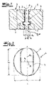
- the figures show a precast concrete slab 1 produced by the method according to the invention with at least one lifting sleeve 2 concreted into the slab 1.
- the slab 1 can be fixed to a transport device, for example a crane, by means of the lifting sleeve 2.
- the lifting sleeve 2 has a first sleeve opening 3 , a sleeve shank 4 for receiving a lifting key 11 and a sleeve end 5 opposite the first sleeve opening 3 .
- the sleeve end 5 is designed as a second sleeve opening 10 .
- the lifting sleeve 2 has an enlarged cross section in the form of a lifting chamber 6 .
- the inner diameter d K of the lifting chamber 6 is greater according to the invention than the inner width bs of the sleeve shank 4. This is particularly the case in FIGS Figures 1 and 2 to recognize.
- Inside diameter d K of the lifting chamber 6 means in the context of the invention and in the exemplary embodiment in particular the largest inside diameter of the lifting chamber transversely, in particular perpendicular to the longitudinal extent or to the longitudinal axis A of the lifting sleeve 2.
- Inside width bs of the sleeve shaft 4 means in the context of the invention and in the exemplary embodiment in particular the largest inner width of the sleeve shank 4 across, in particular perpendicular to the longitudinal extent or to the longitudinal axis A of the lifting sleeve 2 or the sleeve shank 4 and transversely, in particular perpendicular to the longitudinal center axis A Q of the cross-sectional area of the sleeve shank 4. This is particularly the case in FIG 2 shown.
- the ratio of the inside diameter d K of the lifting chamber 6 to the inside width bs of the sleeve shank 4 may be about 2:1.
- At least two lifting sleeves 2 may be concreted into the precast concrete slab 1 . In the embodiment according to 1 only one lifting sleeve 2 is shown.
- the lifting sleeve 2 is hollow on the inside over its entire length L.
- the lifting sleeve 2 is also embedded in concrete over its entire length L or essentially over its entire length L in the precast concrete slab 1 .
- length L of the lifting sleeve 2 means in particular the greatest extension of the lifting sleeve 2 along or in the direction of its longitudinal axis A, as is particularly the case in FIGS 1 and 3 can be seen.
- the first sleeve opening 3 is assigned to the underside 7 of the precast concrete slab 1 and is accessible from the underside 7 of the slab 1 .
- Underside 7 of the precast concrete slab 1 means, within the scope of the invention and in the exemplary embodiment, the side of the slab 1 that faces the mounting substrate when the slab 1 is assembled or laid.
- the lifting key 11 is inserted through the first sleeve opening 3 into the sleeve shank 4 of the lifting sleeve 2 namely from the underside 7 of the plate 1, as in the Figure 4a is shown.
- the sleeve end 5 is designed as a second sleeve opening 10 and this second sleeve opening 10 is associated with the upper side 8 of the plate 1 and is accessible from the upper side 8 of the plate 1 .
- top of the panel in this context means that in the assembled state of the precast concrete slab 1 means the side of the slab 1 facing away from the mounting substrate.
- the lifting chamber 6 is designed as a hollow-cylindrical section of the lifting sleeve 2 .
- the lifting chamber 6 preferably and in the exemplary embodiment has a circular cross section with the inside diameter dK .
- Cross-section of the lifting chamber 6 means in particular the cross-section across, in particular perpendicular to the longitudinal axis A of the lifting sleeve 2.
- the inner diameter d K of the lifting chamber 6, which is designed as a hollow-cylindrical section with a circular cross-section, corresponds within the scope of the invention and in the exemplary embodiment to the circle diameter or inner circle diameter of the cross-sectional area. This is particularly in the 2 to recognize.
- the ratio of the length L H of the lifting chamber 6 to the length L of the lifting sleeve 2 is 1:10 to 1:6, preferably 1:9 to 1:7, particularly preferably and in the exemplary embodiment ( 3 ) 1:8 or about 1:8.
- the length L H of the lifting chamber means in particular the greatest extension of the lifting chamber 6 in the longitudinal direction of the lifting sleeve 2 or in the direction of the longitudinal axis A of the lifting sleeve 2 .
- the sleeve shaft 4 of the lifting sleeve 2 is designed as a hollow body, the inner length Ls of which is recommended and in the exemplary embodiment greater than the inner width bs.
- the inner length Ls of the sleeve shank 4 means in particular the greatest inner length transversely, in particular perpendicularly, to the longitudinal axis A of the lifting sleeve 2 and along or in the direction of the longitudinal center axis A Q of the cross-sectional area of the sleeve shank 4 and thus transversely, in particular perpendicularly to the inner width bs of the sleeve shank 4 ( 2 ).
- the inner length Ls of the sleeve shaft 4 corresponds to the inner diameter dK of the lifting chamber 6 or essentially corresponds to Ls dK Rectangle is formed.
- the longitudinal axis A of the lifting sleeve 2 is arranged transversely, in particular perpendicularly or essentially perpendicularly to the underside 7 and the upper side 8 of the precast concrete slab 1 .
- the longitudinal axis A of the lifting sleeve 2 in the assembled state of the precast concrete slab 1 is preferably oriented transversely, in particular perpendicularly or essentially perpendicularly to the mounting base.
- the lifting chamber 6 is assigned to the end 5 of the sleeve.
- the distance a between the lifting chamber 6 and the sleeve end 5 or the second sleeve opening 10 is preferably between 10% and 35%, particularly preferably between 15% and 30% of the length L of the lifting sleeve 2.
- the distance a between the lifting chamber 6 and the sleeve end 5 may be about 20% of the length L of the lifting sleeve 2 .
- distance a between the lifting chamber 6 and the sleeve end 5 means in particular the greatest distance between the lifting chamber 6 and the sleeve end 5 in the direction/along the longitudinal extension or longitudinal axis A of the lifting sleeve 2, with the length L H being the Lifting chamber 6 itself counts for half of this distance a.
- the lifting sleeve 2 has two anchoring ribs 9 which each completely or substantially completely run around the outer circumference of the lifting sleeve 2 .
- the precast concrete slab 1 in the figures may consist or essentially consist of at least one open-pored concrete.
- the lifting sleeve 2 expediently consists of at least one plastic.
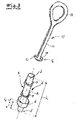
- the lifting wrench 11 has at least one anchor head 12 and at least one guide rod 13 .
- the anchor head 12 is designed in such a way that it can be inserted into the lifting sleeve 2 through a sleeve opening 3, 10 and in the lifting chamber 6 and/or on the underside 7 or upper side 8 of the plate 1 by a rotary movement about the longitudinal axis of the lifting key 11 or the guide rod 13, preferably by 10° to 90°, preferably by about 90°, from an insertion position ( Figure 4a ) to an anchor position ( Figures 4b and 4c ) can be transferred.
- the Hubspanner 11 is in the 3 shown together with the lifting sleeve 2.
- a fastening element 14 is provided on the guide rod 13 of the lifting key 11 on the side opposite the anchor head 12, with which the lifting key 11 can be fixed to a transport device.
- the fastening element 14 is designed as a fastening eyelet.
- lifting key 11 expediently consists of at least one metal.
- the lifting key 11 may consist of steel or essentially consist of steel.
- the lifting sleeve 2 has at least two functions.
- the slab 1 is manufactured in a formwork, with the upper side 7 of the slab 1 facing the bottom of the formwork.
- At least one lifting sleeve 2 is introduced into the plate 1 during the manufacture of the plate 1 .
- a lifting key 11 is inserted into the sleeve shank 4 through the first sleeve opening 3 facing the side intended as the underside 7 of the component in order to remove the plate 1 from the formwork. This is in the Figure 4a shown.
- the lifting key 11 is transferred into an anchoring position.
- This anchoring position is in the Figure 4b shown.
- the lifting key 11 For transfer from the insertion position ( Figure 4a ) to the anchor position ( Figure 4b ) is the lifting key 11 by a rotary movement about the longitudinal axis of the lifting key 11 or the guide rod 13 - rotated - expediently by about 90 °.
- the plate 1 can then be removed or lifted out of the formwork using the lifting key 11 .
- the lifting key 11 is fixed to a transport device by means of the fastening element 14 .
- the lifting sleeve 2 concreted in the plate 1 thus fulfills a first function in the production of the plate 1 ( Figures 4a and 4b ).
- the lifting sleeve 2 is recommended to have an additional function when mounting the plate 1 on the intended mounting base. For the assembly of the plate 1, this is already turned so that the plate underside 7 points in the direction of the mounting surface. This is in the Figure 4c shown.
- the lifting key 11 can be inserted from the top of the plate 8 through the second sleeve opening 10 into the sleeve shank 4 and completely passed through the lifting sleeve 2 in this insertion position. This insertion position during assembly is in the Figures not shown in detail.
- the lifting key 11 on the underside 7 of the plate 1 can then be transferred from the insertion position to the anchoring position by a rotary movement about the longitudinal axis of the lifting key 11 or the guide rod 13 by approximately 90°.
- This anchoring position is in the Figure 4c shown.
- the anchor ends 15 of the anchor head 12 engage behind it, as recommended, and in the exemplary embodiment, a surface 16 of the lifting chamber 6 ( Figure 4b ) or the underside 7 of plate 1 ( Figure 4c ).
Landscapes
- Engineering & Computer Science (AREA)
- Architecture (AREA)
- Civil Engineering (AREA)
- Structural Engineering (AREA)
- Mechanical Engineering (AREA)
- Physics & Mathematics (AREA)
- Electromagnetism (AREA)
- Manufacturing & Machinery (AREA)
- Chemical & Material Sciences (AREA)
- Ceramic Engineering (AREA)
- Manufacturing Of Tubular Articles Or Embedded Moulded Articles (AREA)
- Moulds, Cores, Or Mandrels (AREA)
Claims (11)
- Procédé, destiné à fabriquer un élément de construction en béton préfabriqué, notamment une dalle en béton (1) préfabriquée, l'élément de construction étant produit dans un coffrage, lorsque l'élément de construction est monté, la face de l'élément de construction prévue en tant que face supérieure (8) de l'élément de construction étant dirigée vers le fond inférieur du coffrage,pendant la production de l'élément de construction, au moins un manchon de levage (2) étant introduit dans l'élément de construction, l'élément de construction étant susceptible d'être fixé à l'aide du manchon de levage (2) sur un dispositif de transport,le manchon de levage (2) comportant au moins un premier orifice (3) de manchon, au moins une tige (4) de manchon, destinée à recevoir une clé de levage et une extrémité (5) de manchon, opposée au premier orifice (3) de manchon, le manchon de levage (2) comportant au moins un évasement de section transversale sous la forme d'une chambre de levage (6) et le diamètre intérieur (dK) de la chambre de levage (6) étant supérieur à la largeur intérieure (bs) de la tige (4) de manchon,après le durcissement au moins partiel de l'élément de construction, pour retirer l'élément de construction hors du coffrage, la clé de levage étant introduite dans la tige (4) de manchon, à travers le premier orifice (3) de manchon associé à la face prévue en tant que face inférieure (7) de l'élément de construction et étant amenée dans la chambre de levage (6) dans une position d'ancrage et l'élément de construction étant retiré ensuite hors du coffrage ou levé, à l'aide de la clé de levage,l'extrémité (5) de manchon étant conçue sous la forme de deuxième orifice (10) de manchon, qui lorsque l'élément de construction est monté, est associé à la face supérieure (8) de l'élément de construction qui est opposée au support de montage et qui est accessible à partir de la face supérieure (8) de l'élément de construction etla chambre de levage (6) étant associée à l'extrémité (5) de manchon ou au deuxième orifice (10) de manchon et l'écart (A) entre la chambre de levage (6) et l'extrémité (5) de manchon se situant entre 2 % et 49 % de la longueur (L) du manchon de levage (2).
- Procédé selon la revendication 1, lors duquel l'on bétonne dans l'élément de construction en béton préfabriqué ou dans la dalle en béton (1) préfabriquée au moins deux manchons de levage (2).
- Procédé selon l'une quelconque des revendications 1 ou 2, le manchon de levage (2) étant conçu au moins par endroits en étant creux à l'intérieur et étant conçu de préférence en étant creux à l'intérieur sur toute sa longueur (L) ou sur sensiblement toute sa longueur (L) .
- Procédé selon l'une quelconque des revendications 1 à 3, lors duquel l'on bétonne le manchon de levage (2) sur toute sa longueur (L) ou sur sensiblement toute sa longueur (L) dans l'élément de construction.
- Procédé selon l'une quelconque des revendications 1 à 4, la chambre de levage (6) étant conçue sous la forme d'un tronçon cylindrique creux du manchon de levage (2), qui comporte notamment une section transversale ronde, de préférence circulaire, ayant le diamètre intérieur dK.
- Procédé selon l'une quelconque des revendications 1 à 5, la tige (4) de manchon étant conçue sous la forme d'un corps creux, dont la longueur intérieure (Ls) est de préférence supérieure à sa largeur intérieure (bs).
- Procédé selon l'une quelconque des revendications 1 à 6, l'axe longitudinal (A) du manchon de levage (2) étant placé à la transversale, notamment à la perpendiculaire ou sensiblement à la perpendiculaire de la face inférieure (7) et/ou de la face supérieure (8) de l'élément de construction.
- Procédé selon l'une quelconque des revendications 1 à 7, l'écart (a) entre la chambre de levage (6) et l'extrémité (5) de manchon se situant entre 5 % et 40 %, de manière particulièrement préférentielle, entre 7 % et 35 %, de manière très particulièrement préférentielle, entre 10 % et 30 %, à titre d'exemple, entre 15 % et 25 % de la longueur (L) du manchon de levage (2).
- Procédé selon l'une quelconque des revendications 1 à 8, le manchon de levage (2) comportant au moins une nervure d'ancrage (9) qui entoure totalement ou de manière sensiblement totale la circonférence extérieure du manchon de levage (2) d'au moins 70 %, de préférence, d'au moins 80 %.
- Procédé selon l'une quelconque des revendications 1 à 9, l'élément de construction, respectivement la dalle en béton (1) préfabriquée étant fabriquée sur la base d'au moins un béton à pores ouverts.
- Procédé selon l'une quelconque des revendications 1 à 10, la clé de levage (11) comportant au moins une tête d'ancrage (12) et au moins une barre de guidage (13), la tête d'ancrage (12) étant conçue de sorte à pouvoir être introduite à travers un orifice (3, 10) de manchon dans le manchon de levage (2) et dans la chambre de levage (6) et/ou sur la face inférieure (7) de l'élément de construction, et à pouvoir être amenée par un mouvement en rotation, de préférence autour de l'axe longitudinal de la clé de levage (11) ou de la barre de guidage (12), de préférence de la valeur de 10° à 90°, de manière particulièrement préférentielle, d'environ 90°, d'une position d'introduction dans une position d'ancrage.
Priority Applications (2)
| Application Number | Priority Date | Filing Date | Title |
|---|---|---|---|
| PL20183120.3T PL3933141T3 (pl) | 2020-06-30 | 2020-06-30 | Sposób wytwarzania prefabrykowanego elementu betonowego |
| EP20183120.3A EP3933141B1 (fr) | 2020-06-30 | 2020-06-30 | Procédé pour la fabrication d'un élément en béton préfabriqué |
Applications Claiming Priority (1)
| Application Number | Priority Date | Filing Date | Title |
|---|---|---|---|
| EP20183120.3A EP3933141B1 (fr) | 2020-06-30 | 2020-06-30 | Procédé pour la fabrication d'un élément en béton préfabriqué |
Publications (2)
| Publication Number | Publication Date |
|---|---|
| EP3933141A1 EP3933141A1 (fr) | 2022-01-05 |
| EP3933141B1 true EP3933141B1 (fr) | 2022-07-27 |
Family
ID=71409162
Family Applications (1)
| Application Number | Title | Priority Date | Filing Date |
|---|---|---|---|
| EP20183120.3A Active EP3933141B1 (fr) | 2020-06-30 | 2020-06-30 | Procédé pour la fabrication d'un élément en béton préfabriqué |
Country Status (2)
| Country | Link |
|---|---|
| EP (1) | EP3933141B1 (fr) |
| PL (1) | PL3933141T3 (fr) |
Family Cites Families (5)
| Publication number | Priority date | Publication date | Assignee | Title |
|---|---|---|---|---|
| DE3005975A1 (de) * | 1980-02-18 | 1981-09-03 | Walther Ing.(grad.) 4952 Porta Westfalica Schröder | Vorrichtung zur lastaufnahme von betonfertigteilen |
| DE9111399U1 (de) * | 1991-09-13 | 1991-12-12 | Weidner, Georg, 8771 Steinfeld | Ringanker |
| DE19523476C2 (de) * | 1995-06-28 | 2000-11-02 | Herbert Schulte | Transportsystem für Betonteile |
| JP4137531B2 (ja) * | 1999-07-05 | 2008-08-20 | 株式会社日栄商事 | コンクリート製品の吊上具 |
| EP1293714B1 (fr) * | 2001-09-17 | 2005-07-20 | HILTI Aktiengesellschaft | Passage de conduit, encastrable et expansible |
-
2020
- 2020-06-30 EP EP20183120.3A patent/EP3933141B1/fr active Active
- 2020-06-30 PL PL20183120.3T patent/PL3933141T3/pl unknown
Also Published As
| Publication number | Publication date |
|---|---|
| EP3933141A1 (fr) | 2022-01-05 |
| PL3933141T3 (pl) | 2022-12-27 |
Similar Documents
| Publication | Publication Date | Title |
|---|---|---|
| EP1760208B1 (fr) | Système et procédé pour fabriquer des murs creux isolés | |
| DE2443329B2 (de) | Formstein aus Beton für eine Stützmauer | |
| EP3690159A1 (fr) | Enveloppe de bâtiment et procédé d'isolement thermique des enveloppes de bâtiment en béton | |
| DE60127646T2 (de) | Vorrichtung zum Schutz von Transportankern mit einem rohrförmigen Körper während des Einbetonierens in ein vorgefertigtes Bauteil | |
| EP3190244A1 (fr) | Douille filetée d'ancrage d'éléments de construction dans un ouvrage en béton et entretoise tubulaire | |
| DE69032252T2 (de) | Verankerung und befestigungsverfahren durch in den boden getriebene seitenstützen | |
| EP3933141B1 (fr) | Procédé pour la fabrication d'un élément en béton préfabriqué | |
| DE202009004195U1 (de) | Bewehrungsvorrichtung zur Herstellung eines Fertigbauteils | |
| EP3330448A1 (fr) | Dispositif et procédé de raccordement de deux composants dans une orientation déterminée relative ainsi que construction en béton | |
| DE2724398A1 (de) | Verfahren zum herstellen eines fundamentes, insbesondere fuer schornsteine o.ae. bauwerke, z.b. saeulen, masten, tuerme o.dgl. lehrenartige vorrichtung zur durchfuehrung dieses verfahrens sowie in verbindung mit der lehrenartigen vorrichtung bei dem verfahren zu verwendende verankerungsstaebe | |
| EP3696320B1 (fr) | Culée de pont pourvu de raccordement entre une armature de paroi de coulée et un élément de paroi ailée | |
| EP3263787B1 (fr) | Élément structural en béton préfabriqué, en particulier plaque en béton préfabriqué, ancrage de transport pour un tel élément en béton | |
| EP3851607A1 (fr) | Moyen de positionnement pour une couche de renfort textile doté d'un composant en béton, couche de renfort textile et composant en béton renforcé, comprenant un moyen de positionnement | |
| EP3868954B1 (fr) | Pavé en béton, ainsi que procédé de fabrication d'un pavé en béton | |
| DE2532964C2 (de) | Verfahren zum Herstellen sowie zum Manipulieren eines großformatigen Wand-Fertigbauteils | |
| EP3492665A1 (fr) | Pièce préfabriquée de béton dotée d'au moins un composant recevant la charge ainsi que plaque de raccordement destinée à être agencée dans le joint de raccordement entre une telle pièce préfabriquée de béton et le composant recevant la charge | |
| DE29509260U1 (de) | Transportelement | |
| DE102018122202B4 (de) | Vorrichtung und Verfahren zur Verbindung von textilbewehrten, flächigen Betonelementen zu einer Elementwand sowie Verwendung der Vorrichtung | |
| EP1342847B1 (fr) | Elément de plancher et procédé de réalisation d'un revêtement de sol en utilisant ces éléments | |
| DE102016101360A1 (de) | Fertigteil sowie Verfahren zur Herstellung eines Fertigteils | |
| DE102022119896A1 (de) | Befestigungselement mit Einsatzelement, insbesondere für Solarpanele | |
| DE69500260T2 (de) | Vorrichtung zur Immobilisierung eines glatten, langgestreckten Teils im Loch eines Elements, Anwendungen einer solchen Vorrichtung sowie Herstellungsverfahren eines diese Vorrichtung enthaltenden Formkörpers | |
| DE102007028324B4 (de) | Schacht aus Beton und Lastaufnahmeelement | |
| EP2000726A2 (fr) | Abattoir en béton | |
| DE102015110887A1 (de) | Vorrichtung und Verfahren zum Anheben einer Schachtabdeckung insbesondere Kanaldeckel |
Legal Events
| Date | Code | Title | Description |
|---|---|---|---|
| STAA | Information on the status of an ep patent application or granted ep patent |
Free format text: STATUS: EXAMINATION IS IN PROGRESS |
|
| PUAI | Public reference made under article 153(3) epc to a published international application that has entered the european phase |
Free format text: ORIGINAL CODE: 0009012 |
|
| 17P | Request for examination filed |
Effective date: 20201215 |
|
| AK | Designated contracting states |
Kind code of ref document: A1 Designated state(s): AL AT BE BG CH CY CZ DE DK EE ES FI FR GB GR HR HU IE IS IT LI LT LU LV MC MK MT NL NO PL PT RO RS SE SI SK SM TR |
|
| B565 | Issuance of search results under rule 164(2) epc |
Effective date: 20201117 |
|
| GRAP | Despatch of communication of intention to grant a patent |
Free format text: ORIGINAL CODE: EPIDOSNIGR1 |
|
| STAA | Information on the status of an ep patent application or granted ep patent |
Free format text: STATUS: GRANT OF PATENT IS INTENDED |
|
| INTG | Intention to grant announced |
Effective date: 20220216 |
|
| GRAS | Grant fee paid |
Free format text: ORIGINAL CODE: EPIDOSNIGR3 |
|
| GRAA | (expected) grant |
Free format text: ORIGINAL CODE: 0009210 |
|
| STAA | Information on the status of an ep patent application or granted ep patent |
Free format text: STATUS: THE PATENT HAS BEEN GRANTED |
|
| AK | Designated contracting states |
Kind code of ref document: B1 Designated state(s): AL AT BE BG CH CY CZ DE DK EE ES FI FR GB GR HR HU IE IS IT LI LT LU LV MC MK MT NL NO PL PT RO RS SE SI SK SM TR |
|
| REG | Reference to a national code |
Ref country code: CH Ref legal event code: EP |
|
| REG | Reference to a national code |
Ref country code: DE Ref legal event code: R096 Ref document number: 502020001420 Country of ref document: DE |
|
| REG | Reference to a national code |
Ref country code: AT Ref legal event code: REF Ref document number: 1507170 Country of ref document: AT Kind code of ref document: T Effective date: 20220815 |
|
| REG | Reference to a national code |
Ref country code: IE Ref legal event code: FG4D Free format text: LANGUAGE OF EP DOCUMENT: GERMAN |
|
| REG | Reference to a national code |
Ref country code: NL Ref legal event code: FP |
|
| REG | Reference to a national code |
Ref country code: LT Ref legal event code: MG9D |
|
| PG25 | Lapsed in a contracting state [announced via postgrant information from national office to epo] |
Ref country code: SE Free format text: LAPSE BECAUSE OF FAILURE TO SUBMIT A TRANSLATION OF THE DESCRIPTION OR TO PAY THE FEE WITHIN THE PRESCRIBED TIME-LIMIT Effective date: 20220727 Ref country code: RS Free format text: LAPSE BECAUSE OF FAILURE TO SUBMIT A TRANSLATION OF THE DESCRIPTION OR TO PAY THE FEE WITHIN THE PRESCRIBED TIME-LIMIT Effective date: 20220727 Ref country code: PT Free format text: LAPSE BECAUSE OF FAILURE TO SUBMIT A TRANSLATION OF THE DESCRIPTION OR TO PAY THE FEE WITHIN THE PRESCRIBED TIME-LIMIT Effective date: 20221128 Ref country code: NO Free format text: LAPSE BECAUSE OF FAILURE TO SUBMIT A TRANSLATION OF THE DESCRIPTION OR TO PAY THE FEE WITHIN THE PRESCRIBED TIME-LIMIT Effective date: 20221027 Ref country code: LV Free format text: LAPSE BECAUSE OF FAILURE TO SUBMIT A TRANSLATION OF THE DESCRIPTION OR TO PAY THE FEE WITHIN THE PRESCRIBED TIME-LIMIT Effective date: 20220727 Ref country code: LT Free format text: LAPSE BECAUSE OF FAILURE TO SUBMIT A TRANSLATION OF THE DESCRIPTION OR TO PAY THE FEE WITHIN THE PRESCRIBED TIME-LIMIT Effective date: 20220727 Ref country code: FI Free format text: LAPSE BECAUSE OF FAILURE TO SUBMIT A TRANSLATION OF THE DESCRIPTION OR TO PAY THE FEE WITHIN THE PRESCRIBED TIME-LIMIT Effective date: 20220727 Ref country code: ES Free format text: LAPSE BECAUSE OF FAILURE TO SUBMIT A TRANSLATION OF THE DESCRIPTION OR TO PAY THE FEE WITHIN THE PRESCRIBED TIME-LIMIT Effective date: 20220727 |
|
| PG25 | Lapsed in a contracting state [announced via postgrant information from national office to epo] |
Ref country code: IS Free format text: LAPSE BECAUSE OF FAILURE TO SUBMIT A TRANSLATION OF THE DESCRIPTION OR TO PAY THE FEE WITHIN THE PRESCRIBED TIME-LIMIT Effective date: 20221127 Ref country code: HR Free format text: LAPSE BECAUSE OF FAILURE TO SUBMIT A TRANSLATION OF THE DESCRIPTION OR TO PAY THE FEE WITHIN THE PRESCRIBED TIME-LIMIT Effective date: 20220727 Ref country code: GR Free format text: LAPSE BECAUSE OF FAILURE TO SUBMIT A TRANSLATION OF THE DESCRIPTION OR TO PAY THE FEE WITHIN THE PRESCRIBED TIME-LIMIT Effective date: 20221028 |
|
| PG25 | Lapsed in a contracting state [announced via postgrant information from national office to epo] |
Ref country code: SM Free format text: LAPSE BECAUSE OF FAILURE TO SUBMIT A TRANSLATION OF THE DESCRIPTION OR TO PAY THE FEE WITHIN THE PRESCRIBED TIME-LIMIT Effective date: 20220727 Ref country code: RO Free format text: LAPSE BECAUSE OF FAILURE TO SUBMIT A TRANSLATION OF THE DESCRIPTION OR TO PAY THE FEE WITHIN THE PRESCRIBED TIME-LIMIT Effective date: 20220727 Ref country code: DK Free format text: LAPSE BECAUSE OF FAILURE TO SUBMIT A TRANSLATION OF THE DESCRIPTION OR TO PAY THE FEE WITHIN THE PRESCRIBED TIME-LIMIT Effective date: 20220727 |
|
| REG | Reference to a national code |
Ref country code: DE Ref legal event code: R097 Ref document number: 502020001420 Country of ref document: DE |
|
| PG25 | Lapsed in a contracting state [announced via postgrant information from national office to epo] |
Ref country code: SK Free format text: LAPSE BECAUSE OF FAILURE TO SUBMIT A TRANSLATION OF THE DESCRIPTION OR TO PAY THE FEE WITHIN THE PRESCRIBED TIME-LIMIT Effective date: 20220727 Ref country code: EE Free format text: LAPSE BECAUSE OF FAILURE TO SUBMIT A TRANSLATION OF THE DESCRIPTION OR TO PAY THE FEE WITHIN THE PRESCRIBED TIME-LIMIT Effective date: 20220727 |
|
| PLBE | No opposition filed within time limit |
Free format text: ORIGINAL CODE: 0009261 |
|
| STAA | Information on the status of an ep patent application or granted ep patent |
Free format text: STATUS: NO OPPOSITION FILED WITHIN TIME LIMIT |
|
| PG25 | Lapsed in a contracting state [announced via postgrant information from national office to epo] |
Ref country code: AL Free format text: LAPSE BECAUSE OF FAILURE TO SUBMIT A TRANSLATION OF THE DESCRIPTION OR TO PAY THE FEE WITHIN THE PRESCRIBED TIME-LIMIT Effective date: 20220727 |
|
| 26N | No opposition filed |
Effective date: 20230502 |
|
| PGFP | Annual fee paid to national office [announced via postgrant information from national office to epo] |
Ref country code: CZ Payment date: 20230623 Year of fee payment: 4 |
|
| PGFP | Annual fee paid to national office [announced via postgrant information from national office to epo] |
Ref country code: PL Payment date: 20230623 Year of fee payment: 4 |
|
| PGFP | Annual fee paid to national office [announced via postgrant information from national office to epo] |
Ref country code: CH Payment date: 20230702 Year of fee payment: 4 |
|
| PG25 | Lapsed in a contracting state [announced via postgrant information from national office to epo] |
Ref country code: MC Free format text: LAPSE BECAUSE OF FAILURE TO SUBMIT A TRANSLATION OF THE DESCRIPTION OR TO PAY THE FEE WITHIN THE PRESCRIBED TIME-LIMIT Effective date: 20220727 |
|
| PG25 | Lapsed in a contracting state [announced via postgrant information from national office to epo] |
Ref country code: MC Free format text: LAPSE BECAUSE OF FAILURE TO SUBMIT A TRANSLATION OF THE DESCRIPTION OR TO PAY THE FEE WITHIN THE PRESCRIBED TIME-LIMIT Effective date: 20220727 |
|
| PG25 | Lapsed in a contracting state [announced via postgrant information from national office to epo] |
Ref country code: LU Free format text: LAPSE BECAUSE OF NON-PAYMENT OF DUE FEES Effective date: 20230630 |
|
| REG | Reference to a national code |
Ref country code: IE Ref legal event code: MM4A |
|
| PG25 | Lapsed in a contracting state [announced via postgrant information from national office to epo] |
Ref country code: LU Free format text: LAPSE BECAUSE OF NON-PAYMENT OF DUE FEES Effective date: 20230630 |
|
| PG25 | Lapsed in a contracting state [announced via postgrant information from national office to epo] |
Ref country code: IE Free format text: LAPSE BECAUSE OF NON-PAYMENT OF DUE FEES Effective date: 20230630 |
|
| PG25 | Lapsed in a contracting state [announced via postgrant information from national office to epo] |
Ref country code: IE Free format text: LAPSE BECAUSE OF NON-PAYMENT OF DUE FEES Effective date: 20230630 |
|
| PG25 | Lapsed in a contracting state [announced via postgrant information from national office to epo] |
Ref country code: IT Free format text: LAPSE BECAUSE OF FAILURE TO SUBMIT A TRANSLATION OF THE DESCRIPTION OR TO PAY THE FEE WITHIN THE PRESCRIBED TIME-LIMIT Effective date: 20220727 |
|
| PGFP | Annual fee paid to national office [announced via postgrant information from national office to epo] |
Ref country code: DE Payment date: 20240529 Year of fee payment: 5 |
|
| PGFP | Annual fee paid to national office [announced via postgrant information from national office to epo] |
Ref country code: NL Payment date: 20240619 Year of fee payment: 5 |
|
| PGFP | Annual fee paid to national office [announced via postgrant information from national office to epo] |
Ref country code: FR Payment date: 20240628 Year of fee payment: 5 |
|
| PGFP | Annual fee paid to national office [announced via postgrant information from national office to epo] |
Ref country code: BE Payment date: 20240619 Year of fee payment: 5 |