EP2000726A2 - Abattoir en béton - Google Patents
Abattoir en béton Download PDFInfo
- Publication number
- EP2000726A2 EP2000726A2 EP08010098A EP08010098A EP2000726A2 EP 2000726 A2 EP2000726 A2 EP 2000726A2 EP 08010098 A EP08010098 A EP 08010098A EP 08010098 A EP08010098 A EP 08010098A EP 2000726 A2 EP2000726 A2 EP 2000726A2
- Authority
- EP
- European Patent Office
- Prior art keywords
- load
- web
- receiving element
- ring
- bearing element
- Prior art date
- Legal status (The legal status is an assumption and is not a legal conclusion. Google has not performed a legal analysis and makes no representation as to the accuracy of the status listed.)
- Withdrawn
Links
Images


Classifications
-
- E—FIXED CONSTRUCTIONS
- E02—HYDRAULIC ENGINEERING; FOUNDATIONS; SOIL SHIFTING
- E02D—FOUNDATIONS; EXCAVATIONS; EMBANKMENTS; UNDERGROUND OR UNDERWATER STRUCTURES
- E02D29/00—Independent underground or underwater structures; Retaining walls
- E02D29/12—Manhole shafts; Other inspection or access chambers; Accessories therefor
- E02D29/14—Covers for manholes or the like; Frames for covers
- E02D29/1463—Hinged connection of cover to frame
-
- F—MECHANICAL ENGINEERING; LIGHTING; HEATING; WEAPONS; BLASTING
- F16—ENGINEERING ELEMENTS AND UNITS; GENERAL MEASURES FOR PRODUCING AND MAINTAINING EFFECTIVE FUNCTIONING OF MACHINES OR INSTALLATIONS; THERMAL INSULATION IN GENERAL
- F16L—PIPES; JOINTS OR FITTINGS FOR PIPES; SUPPORTS FOR PIPES, CABLES OR PROTECTIVE TUBING; MEANS FOR THERMAL INSULATION IN GENERAL
- F16L21/00—Joints with sleeve or socket
- F16L21/02—Joints with sleeve or socket with elastic sealing rings between pipe and sleeve or between pipe and socket, e.g. with rolling or other prefabricated profiled rings
-
- F—MECHANICAL ENGINEERING; LIGHTING; HEATING; WEAPONS; BLASTING
- F16—ENGINEERING ELEMENTS AND UNITS; GENERAL MEASURES FOR PRODUCING AND MAINTAINING EFFECTIVE FUNCTIONING OF MACHINES OR INSTALLATIONS; THERMAL INSULATION IN GENERAL
- F16L—PIPES; JOINTS OR FITTINGS FOR PIPES; SUPPORTS FOR PIPES, CABLES OR PROTECTIVE TUBING; MEANS FOR THERMAL INSULATION IN GENERAL
- F16L23/00—Flanged joints
- F16L23/02—Flanged joints the flanges being connected by members tensioned axially
- F16L23/032—Flanged joints the flanges being connected by members tensioned axially characterised by the shape or composition of the flanges
Definitions
- the invention relates to a shaft made of concrete according to the preamble of claim 1 and a load-bearing element according to the preamble of claim 2.
- the shaft comprises at least a first manhole ring and a second manhole ring, the manhole rings each having an upper and a lower edge, wherein at least the first manhole ring at its cooperating with the second manhole lower ring more strip-shaped load-bearing elements made of plastic distributed at the edge spaced from each other on the circumference, wherein the single load-receiving element is embedded with a foot in the edge and protrudes with a head portion over an end face of the edge, wherein in the assembled state of the shaft of the second manhole ring with its upper edge bears against the head part of the load-receiving element and has a distance from the lower edge of the first manhole ring in which the load-bearing element is fastened.
- a shaft made of concrete was observed that when moving the manhole rings on the site repeatedly solves individual load-bearing elements from the concrete body of the manhole ring and lost before the questionable man
- the load-receiving element for integration into one of the manhole rings has two parallel to each other and in the direction of a longitudinal extent of the strip-shaped load-receiving element extending webs which are integrated into the concrete body of the manhole ring.
- Such a design makes manual pre-assembly of the load-bearing element using a hammer in the lower sleeve difficult, since usually only one of the webs is hit by the hammer and the hammer slips off or the load-receiving element is slanted into the recess of the lower sleeve and on whose edge is tilted or damaged.
- the invention has for its object to develop a manhole made of concrete or a load-bearing element, which does not lose individual components even under rough site conditions and ensures easy and safe manual assembly of these components or which even under harsh site conditions safely with a manhole in Connection remains safe and easy to manually pre-assembled.
- the concrete shaft according to the invention comprises at least one manhole ring with at least one load-receiving element, in which the web extends obliquely or transversely over the foot surface to a longitudinal extent of the load-receiving element extending longitudinal axis of the load-receiving element on the foot surface of the load-receiving element and in which the foot surface of the load-bearing element laterally forms at least one striking surface, wherein the load-receiving element can be driven on the at least one striking surface into a recess in a lower sleeve of a mold for producing the manhole ring with a tool.
- a shaft according to the invention with a manhole ring which comprises such a load-bearing element no individual components of the manhole ring are lost even under harsh site conditions, whereby manual assembly of the load-bearing element is still simple.
- the core of the invention is thus a shaft in which the or the load-bearing elements are securely held by the concrete in the individual manhole rings and still in the manufacture of the individual manhole ring of the shaft in a conventional manner in the concrete factory by hammer blows in a lower sleeve of the mold are pre-assembled.
- the load-bearing element according to the invention for concreting into a manhole ring has at least one web extending obliquely or transversely to a longitudinal extent of the load-receiving member extending longitudinal axis of the load-receiving member from the foot surface of the load-receiving element, wherein the foot surface of the load-receiving element laterally of the web at least forms a club face and wherein the load-receiving element on the at least one impact surface in a recess in a lower sleeve of a mold for the production of the manhole ring with a tool is einschlagbar.
- Such a load-bearing element is by its least a bridge suitable to remain secure under rough site conditions with a manhole ring in conjunction and is despite the at least one bar for a safe and easy manual pre-assembly to a bottom sleeve in the production of a manhole for a manhole.
- the invention provides to form the web over an entire width of the load-receiving element. In this way, in spite of the obliquely or transversely to the longitudinal direction of the load-receiving element extending web for the pouring into concrete sufficiently stable web is achieved.
- a form-fitting embedding of the load-bearing element with its web is provided in the manhole ring.
- the load-bearing element is held particularly secure in the concrete body of the manhole ring.
- the invention provides at least a temporary widening of the web in the direction of its approximately parallel to the foot surface upper edge.
- the web receives a barb-shaped or mushroom-shaped in side view or in cross-section, which allows a particularly effective form-fitting retention of the load-bearing element in the concrete body of the manhole ring.
- a further embodiment provides to provide the web with a surface that is studded with knobs and / or pins. Also at the knobs and / or pins arises in the manufacture of the chess ring of the desired form fit.
- the invention provides to form the web with a measured by the foot surface of the load compensation element height of at least 1.5 cm.
- This will be an embedding achieved in the concrete body of the manhole ring through which the load-bearing element is held securely against the concrete body of the manhole ring despite greater external forces.
- Such forces can occur, for example, when a chess ring is rotated with respect to another chess ring in two superposed chess rings, without the chess rings are sufficiently separated from each other for this purpose.
- the invention also provides for arranging at least two domes on the head part of the load-bearing element, which are aligned with their longitudinal axes in the direction of the force flow between two stacked race rings and have congruent cross-sectional areas perpendicular to the direction of the force flow towards the opposite shaft ring.
- Such an inclination or transverse position of the web on the foot surface or the base body with respect to the longitudinal axis of the load-receiving element ensures sufficiently large playing surfaces.
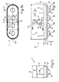
- FIGS. 1a to 1c is a first inventive load-receiving element 1 shown in three different views.
- This load-receiving element 1 is intended for installation in a first manhole ring 2 of a shaft 3, the shaft 3 comprising the first manhole ring 2 and a second manhole ring 4 (see FIG FIG. 4 ).
- the load-bearing element 1 is shown in a side view.
- the load-bearing element 1 comprises a foot part 5 and a head part 6.
- the head part 6 comprises four domes 7a, 7b, 7c and 7d, which have parallel longitudinal axes L7a, L7b, L7c and L7d, and a strip-shaped top OT of a main body G.
- the foot part 5 of the load-bearing element 1 comprises a web 8, which consists of a foot surface 9 of a strip-shaped lower part UT of the main body G rises.
- the web 8 thickened from a width B81 to a width B82 and then tapers again. This results in the side view or in section, a surface F8 mushroom-like shape.
- the web 8 is transverse to a longitudinal extent L1, or a longitudinal axis LA1 of the load-bearing element 1 on the bottom surface 9 or the lower part UT of the body G. This is especially in the in the FIG.
- FIG. 1b shown lower view, which in the FIG. 1a shown load-receiving element 1 from an arrow direction Ib shows. Dashed lines here edges of a web neck 12 and a web head 13 of the web 8 are indicated.
- the web 8 extends over a width B1 of the load-bearing element 1 and in this case has a length L8.
- the foot surface 9 is divided into a first impact surface 14 and a second impact surface 15. About these impact surfaces 14 and 15, the load-bearing element 1 with a tool 16 (see FIG.
- FIG. 3a shows a view of the in the FIG. 1a shown load-receiving element 1 from an arrow direction Ic.
- an upper edge 18 of the web 8 can be seen, which runs parallel to the foot surface 9.
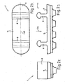
- FIGS. 2a to 2c is in views that match the views of the FIGS. 1a to 1c are comparable, a second load-receiving element 1 shown, wherein the FIG. 2b a plan view from an arrow direction IIb on in the FIG. 2a illustrated load-receiving element 1, shows.
- FIG. 2b a plan view from an arrow direction IIb on in the FIG. 2a illustrated load-receiving element 1
- FIG. 2b a plan view from an arrow direction IIb on in the FIG. 2a illustrated load-receiving element 1
- a foot surface 9 of the load-bearing element 1 forms a striking surface 14 between the two webs 8.
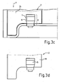
- FIGS. 3a to 3d show schematic representation of the manufacturing steps for the above-mentioned first manhole ring 2.
- the manhole ring 2 consists essentially of a concrete body 19 and a plurality of load-bearing elements 8 (see 3d figure ).
- the load-bearing elements 1 are first hammered into recesses 20 of the lower sleeve 17 already mentioned above with the abovementioned tool 16 in an arrow direction or a mounting direction or direction of insertion y.
- the recesses 20 are designed so that the load-receiving element 8 with an upper part OT of its base body G fits into the recess 20 by clamping.
- FIGS. 3a to 3d show load-receiving element 8 comparable to that in the Figures 1 a to 1 c shown load-receiving element is formed.
- a mold 21, to which the lower sleeve 17 belongs is completed by a core 22 and an outer ring 23 (see FIG FIG. 3b ).
- concrete 24 is filled into an interior 25 of the mold 21 from above.
- the flowing in the direction of arrow y in the interior 25 of the mold 21 concrete 24 flows around during filling and compaction foot parts 5 of the load-bearing elements 1.
- the load-bearing elements 1 are then held by their webs 8 8 form-fitting in the concrete 24.
- a section of the chess ring 2 is shown after demoulding.
- the above-mentioned shaft 3 is shown, which is composed of the first chess ring 2 and the second manhole ring 4 composed.
- the first manhole ring 2 has an upper annular rim 26 and a lower annular rim 27.
- the second manhole ring 4 has an upper annular rim 28 and a lower annular rim 29.
- the first or upper manhole ring 2 lies with its lower edge 27 opposite the upper edge 28 of the second, lower manhole ring 4.
- a contact of the edges 27 and 28 of the manhole rings 2 and 4 is prevented by the uniformly spaced over the annular edge 27 of the upper manhole ring 2 and over the end face F27 in the direction of arrow y outgoing load-bearing elements 1.
- the first upper chess ring 2 rests exclusively with domes 7a to 7d of head parts 6 of its load-bearing elements 1 on the upper edge 28 of the second, lower chess ring 4.
- the domes 7a to 7d are slightly compressed or deformed by the weight of the concrete body 19 of the first manhole ring 2.
- the upper manhole ring 2 and the lower manhole ring 4 are held at a distance D3 to each other.
- the load-bearing elements 1 are held reliably by their intimate connection with the concrete body 19 of the manhole ring 2 when demoulding the manhole ring 2, during the transport of the manhole ring 2 and when moving the manhole ring 2.
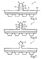
- FIGS. 5 to 11b show a third to ninth embodiment of load-bearing elements 1, which differ substantially by the construction of their webs 8.
- the bridge 8 of the in the FIG. 5 shown load-receiving element 1 is reinforced by two thin ribs R1 and R2.
- the ribs R1 and R2 extend perpendicular to a longitudinal axis LA1 of the load-bearing element 1 from a web head 13 parallel to a web neck 12 onto a foot surface 9.
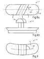
- the bridge 8 of the in the FIG. 6 shown load receiving element 1 is characterized by a web head 13, which is composed in the illustrated side view of two arrowheads P131 and P132.
- the web 8 in addition to the undercuts 10 and 11, two further undercuts 30 and 31.
- the bridge 8 of the in the FIG. 7 shown load-receiving element 1 is characterized by a solid web head 13, which is adapted to form a particularly effective abutment in a concrete body, in which this is poured.
- FIGS. 8a and 8b illustrated load balancing element 1 is shown with the omission of domes and has a web 8, which in terms of its shape similar to that in the FIGS. 1a to 1c is shown formed web.
- the bridge 8 of the in the FIGS. 8a and 8b shown load compensation element 1 is shown at an angle ⁇ of 63 ° to a longitudinal axis LA1 of the load compensation element 1 and divides a foot surface 9 in two impact surfaces 14 and 15th
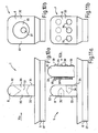
- load compensation element 1 extends a longitudinal axis LA1 arcuately on a curved body G and is adapted to a radius of a lower sleeve or a chess ring.
- load balancing element 1 is shown omitting arranged on an upper part OT of a body G domes and has a web 8, the surface 32 at two opposite side surfaces 33 and 34 each have a bore 35, 36, wherein the two bores 35, 36 a Breakthrough 37 form.
- the load-bearing element 1 flows liquid concrete in the holes 35, 36th and embeds the load-bearing element 1 in a form-fitting manner into the hardening concrete body of the manhole ring.
- FIG. 10b is that in the FIG. 10a shown load balancing element 1 from a in the FIG. 10a shown arrow Xb shown.
- FIG. 11b that in the Figures 11a and 11b illustrated load compensation element 1 is shown omitting arranged on an upper part OT of a body G domes and has a web 8, the surface 32 at two opposite side surfaces 33 and 34 each have three mutually offset bores 35, 36 has.
- FIG. 11b is that in the FIG. 11a shown load balancing element 1 from a in the FIG. 11a shown arrow direction xIb shown.
- FIG. 11a a second illustration of a web 8 is shown, in which opposite side surfaces 33, 34 are studded with nubs 38 and pins 39, in order to achieve an optimal hold of the Lastaufilahmeelements 1 in a concrete ring.
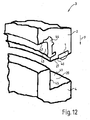
- FIG. 12 is a perspective view of a section of a further shaft according to the invention 3 shown.
- the shaft 3 comprises a first manhole ring 2 and a second manhole ring 4.
- the first manhole ring 2 has a lower annular edge 27.
- the second manhole ring 4 has an upper annular rim 28.
- the manhole ring 2 is lowered in an arrow y direction on the manhole ring 4.
- the upper chute ring 2 sets with load-bearing elements 1, which are distributed at equal intervals over the annular edge 27 and an outer shoulder 40 of the upper chess ring 2, on an outer shoulder 41 of the lower chess ring 4.
- load-bearing elements 1 which are distributed at equal intervals over the annular edge 27 and an outer shoulder 40 of the upper chess ring 2, on an outer shoulder 41 of the lower chess ring 4.
Landscapes
- Engineering & Computer Science (AREA)
- General Engineering & Computer Science (AREA)
- Mechanical Engineering (AREA)
- Environmental & Geological Engineering (AREA)
- Life Sciences & Earth Sciences (AREA)
- General Life Sciences & Earth Sciences (AREA)
- Mining & Mineral Resources (AREA)
- Paleontology (AREA)
- Civil Engineering (AREA)
- Structural Engineering (AREA)
- Underground Structures, Protecting, Testing And Restoring Foundations (AREA)
- Ladders (AREA)
Applications Claiming Priority (2)
| Application Number | Priority Date | Filing Date | Title |
|---|---|---|---|
| DE102007026846 | 2007-06-06 | ||
| DE102007028324.7A DE102007028324B4 (de) | 2007-06-06 | 2007-06-15 | Schacht aus Beton und Lastaufnahmeelement |
Publications (2)
| Publication Number | Publication Date |
|---|---|
| EP2000726A2 true EP2000726A2 (fr) | 2008-12-10 |
| EP2000726A3 EP2000726A3 (fr) | 2008-12-31 |
Family
ID=39736962
Family Applications (1)
| Application Number | Title | Priority Date | Filing Date |
|---|---|---|---|
| EP08010098A Withdrawn EP2000726A3 (fr) | 2007-06-06 | 2008-06-03 | Abattoir en béton |
Country Status (1)
| Country | Link |
|---|---|
| EP (1) | EP2000726A3 (fr) |
Cited By (2)
| Publication number | Priority date | Publication date | Assignee | Title |
|---|---|---|---|---|
| US20130055650A1 (en) * | 2010-11-17 | 2013-03-07 | Udo Hartmann | Modular Integrated Underground Utilities Enclosure and Distribution System |
| DE102011105334B4 (de) | 2011-04-21 | 2024-11-21 | Hans Rinninger u. Sohn GmbH & Co. KG | Schacht aus Beton und Lastaufnahmeelement |
Citations (1)
| Publication number | Priority date | Publication date | Assignee | Title |
|---|---|---|---|---|
| WO2004106798A1 (fr) | 2003-05-28 | 2004-12-09 | Trelleborg Forsheda Building Ab | Bande en caoutchouc destinee a etre partiellement incorporee dans une conduite en beton, conduite en beton comprenant la bande en caoutchouc partiellement incorporee et bague inferieure pour moule a beton servant a couler une conduite en beton comprenant une bande en caoutchouc |
Family Cites Families (3)
| Publication number | Priority date | Publication date | Assignee | Title |
|---|---|---|---|---|
| FR1594313A (fr) * | 1968-12-11 | 1970-06-01 | ||
| DE19538113C2 (de) * | 1995-10-13 | 1997-09-04 | Pt Poly Tec Gmbh | Stoßpolster an zusammensteckbaren, rohrartigen Betonfertigteilen sowie Werkzeug und Verfahren zur Herstellung einer Glockenmuffe |
| CH697312B1 (de) * | 2003-09-04 | 2008-08-15 | Patentanwalt Dipl Ing Uni Wolf | Lastübertragungseinrichtung für Schachtbauteile. |
-
2008
- 2008-06-03 EP EP08010098A patent/EP2000726A3/fr not_active Withdrawn
Patent Citations (1)
| Publication number | Priority date | Publication date | Assignee | Title |
|---|---|---|---|---|
| WO2004106798A1 (fr) | 2003-05-28 | 2004-12-09 | Trelleborg Forsheda Building Ab | Bande en caoutchouc destinee a etre partiellement incorporee dans une conduite en beton, conduite en beton comprenant la bande en caoutchouc partiellement incorporee et bague inferieure pour moule a beton servant a couler une conduite en beton comprenant une bande en caoutchouc |
Cited By (2)
| Publication number | Priority date | Publication date | Assignee | Title |
|---|---|---|---|---|
| US20130055650A1 (en) * | 2010-11-17 | 2013-03-07 | Udo Hartmann | Modular Integrated Underground Utilities Enclosure and Distribution System |
| DE102011105334B4 (de) | 2011-04-21 | 2024-11-21 | Hans Rinninger u. Sohn GmbH & Co. KG | Schacht aus Beton und Lastaufnahmeelement |
Also Published As
| Publication number | Publication date |
|---|---|
| EP2000726A3 (fr) | 2008-12-31 |
Similar Documents
| Publication | Publication Date | Title |
|---|---|---|
| DE69803766T2 (de) | Bausystem mit individuellen bauelementen | |
| EP1929109B1 (fr) | Concept de tour | |
| DE69505800T2 (de) | Ankerhülse | |
| DE3526940A1 (de) | Anker zum einbetonieren in schwere lasten | |
| DE2910090A1 (de) | Dichtungsstreifen zum abdichten von stossfugen und kreuzungsstellen zwischen bauelementen | |
| EP0449082B1 (fr) | Raccord à manchon | |
| EP0059171B1 (fr) | Boulon et canon pour la prise et la transmission d'une force transversale | |
| DE60127646T2 (de) | Vorrichtung zum Schutz von Transportankern mit einem rohrförmigen Körper während des Einbetonierens in ein vorgefertigtes Bauteil | |
| CH665464A5 (de) | Steckmuffendichtung an einem betonrohr. | |
| WO2012163856A1 (fr) | Ensemble d'assemblage et procédé de production d'une consolidation contre la perforation, d'un renfort de force transversale supplémentaire ou d'un raccordement d'armature | |
| EP1745182A1 (fr) | Element de connexion de dalle en console | |
| DE8916127U1 (de) | Vorrichtung zur federnden Einspannung von Traversen einer Fahrbahnüberbrückungskonstruktion | |
| EP2000726A2 (fr) | Abattoir en béton | |
| AT508406A1 (de) | Halbfertigteil zur herstellung von wänden von bauwerken sowie verfahren zu dessen herstellung | |
| DE102007028324B4 (de) | Schacht aus Beton und Lastaufnahmeelement | |
| DE102011105334B4 (de) | Schacht aus Beton und Lastaufnahmeelement | |
| AT406602B (de) | Fugendübel | |
| EP3921514B1 (fr) | Voussoir de tunnel en béton armé | |
| WO2012126025A1 (fr) | Dispositif pour réaliser un joint de dilatation | |
| DE202017107261U1 (de) | Betonfertigteil mit mindestens einem eine Last aufnehmenden Bauteil | |
| EP3933141B1 (fr) | Procédé pour la fabrication d'un élément en béton préfabriqué | |
| DE10119988B4 (de) | Verdübelungs-Vorrichtung für die Ringelemente einer Tübbingauskleidung für unterirdische Bauwerke | |
| EP3680407A1 (fr) | Élément d'insertion et avaloir | |
| DE102011056105B4 (de) | Montagezusatzelement für die Befestigung von Bauelementen, z.B. Kellerlichtschächten an Gebäudewänden | |
| DE102005015680A1 (de) | Schachtfertigteil aus Beton |
Legal Events
| Date | Code | Title | Description |
|---|---|---|---|
| PUAI | Public reference made under article 153(3) epc to a published international application that has entered the european phase |
Free format text: ORIGINAL CODE: 0009012 |
|
| PUAL | Search report despatched |
Free format text: ORIGINAL CODE: 0009013 |
|
| AK | Designated contracting states |
Kind code of ref document: A2 Designated state(s): AT BE BG CH CY CZ DE DK EE ES FI FR GB GR HR HU IE IS IT LI LT LU LV MC MT NL NO PL PT RO SE SI SK TR |
|
| AX | Request for extension of the european patent |
Extension state: AL BA MK RS |
|
| AK | Designated contracting states |
Kind code of ref document: A3 Designated state(s): AT BE BG CH CY CZ DE DK EE ES FI FR GB GR HR HU IE IS IT LI LT LU LV MC MT NL NO PL PT RO SE SI SK TR |
|
| AX | Request for extension of the european patent |
Extension state: AL BA MK RS |
|
| 17P | Request for examination filed |
Effective date: 20090415 |
|
| 17Q | First examination report despatched |
Effective date: 20090513 |
|
| AKX | Designation fees paid |
Designated state(s): AT CH DE IT LI |
|
| GRAP | Despatch of communication of intention to grant a patent |
Free format text: ORIGINAL CODE: EPIDOSNIGR1 |
|
| STAA | Information on the status of an ep patent application or granted ep patent |
Free format text: STATUS: THE APPLICATION IS DEEMED TO BE WITHDRAWN |
|
| 18D | Application deemed to be withdrawn |
Effective date: 20120524 |