EP3928989B1 - Flüssigkeitsausstosskopf und drucker - Google Patents
Flüssigkeitsausstosskopf und drucker Download PDFInfo
- Publication number
- EP3928989B1 EP3928989B1 EP20209865.3A EP20209865A EP3928989B1 EP 3928989 B1 EP3928989 B1 EP 3928989B1 EP 20209865 A EP20209865 A EP 20209865A EP 3928989 B1 EP3928989 B1 EP 3928989B1
- Authority
- EP
- European Patent Office
- Prior art keywords
- pressure chamber
- pulse
- time point
- contraction pulse
- drive circuit
- Prior art date
- Legal status (The legal status is an assumption and is not a legal conclusion. Google has not performed a legal analysis and makes no representation as to the accuracy of the status listed.)
- Active
Links
Images



Classifications
-
- B—PERFORMING OPERATIONS; TRANSPORTING
- B41—PRINTING; LINING MACHINES; TYPEWRITERS; STAMPS
- B41J—TYPEWRITERS; SELECTIVE PRINTING MECHANISMS, i.e. MECHANISMS PRINTING OTHERWISE THAN FROM A FORME; CORRECTION OF TYPOGRAPHICAL ERRORS
- B41J2/00—Typewriters or selective printing mechanisms characterised by the printing or marking process for which they are designed
- B41J2/005—Typewriters or selective printing mechanisms characterised by the printing or marking process for which they are designed characterised by bringing liquid or particles selectively into contact with a printing material
- B41J2/01—Ink jet
- B41J2/015—Ink jet characterised by the jet generation process
- B41J2/04—Ink jet characterised by the jet generation process generating single droplets or particles on demand
- B41J2/045—Ink jet characterised by the jet generation process generating single droplets or particles on demand by pressure, e.g. electromechanical transducers
- B41J2/04501—Control methods or devices therefor, e.g. driver circuits, control circuits
- B41J2/04581—Control methods or devices therefor, e.g. driver circuits, control circuits controlling heads based on piezoelectric elements
-
- B—PERFORMING OPERATIONS; TRANSPORTING
- B41—PRINTING; LINING MACHINES; TYPEWRITERS; STAMPS
- B41J—TYPEWRITERS; SELECTIVE PRINTING MECHANISMS, i.e. MECHANISMS PRINTING OTHERWISE THAN FROM A FORME; CORRECTION OF TYPOGRAPHICAL ERRORS
- B41J2/00—Typewriters or selective printing mechanisms characterised by the printing or marking process for which they are designed
- B41J2/005—Typewriters or selective printing mechanisms characterised by the printing or marking process for which they are designed characterised by bringing liquid or particles selectively into contact with a printing material
- B41J2/01—Ink jet
- B41J2/015—Ink jet characterised by the jet generation process
-
- B—PERFORMING OPERATIONS; TRANSPORTING
- B41—PRINTING; LINING MACHINES; TYPEWRITERS; STAMPS
- B41J—TYPEWRITERS; SELECTIVE PRINTING MECHANISMS, i.e. MECHANISMS PRINTING OTHERWISE THAN FROM A FORME; CORRECTION OF TYPOGRAPHICAL ERRORS
- B41J2/00—Typewriters or selective printing mechanisms characterised by the printing or marking process for which they are designed
- B41J2/005—Typewriters or selective printing mechanisms characterised by the printing or marking process for which they are designed characterised by bringing liquid or particles selectively into contact with a printing material
- B41J2/01—Ink jet
- B41J2/015—Ink jet characterised by the jet generation process
- B41J2/04—Ink jet characterised by the jet generation process generating single droplets or particles on demand
- B41J2/045—Ink jet characterised by the jet generation process generating single droplets or particles on demand by pressure, e.g. electromechanical transducers
- B41J2/04501—Control methods or devices therefor, e.g. driver circuits, control circuits
- B41J2/04588—Control methods or devices therefor, e.g. driver circuits, control circuits using a specific waveform
-
- B—PERFORMING OPERATIONS; TRANSPORTING
- B41—PRINTING; LINING MACHINES; TYPEWRITERS; STAMPS
- B41J—TYPEWRITERS; SELECTIVE PRINTING MECHANISMS, i.e. MECHANISMS PRINTING OTHERWISE THAN FROM A FORME; CORRECTION OF TYPOGRAPHICAL ERRORS
- B41J2/00—Typewriters or selective printing mechanisms characterised by the printing or marking process for which they are designed
- B41J2/005—Typewriters or selective printing mechanisms characterised by the printing or marking process for which they are designed characterised by bringing liquid or particles selectively into contact with a printing material
- B41J2/01—Ink jet
- B41J2/015—Ink jet characterised by the jet generation process
- B41J2/04—Ink jet characterised by the jet generation process generating single droplets or particles on demand
- B41J2/045—Ink jet characterised by the jet generation process generating single droplets or particles on demand by pressure, e.g. electromechanical transducers
- B41J2/04501—Control methods or devices therefor, e.g. driver circuits, control circuits
- B41J2/04591—Width of the driving signal being adjusted
-
- B—PERFORMING OPERATIONS; TRANSPORTING
- B41—PRINTING; LINING MACHINES; TYPEWRITERS; STAMPS
- B41J—TYPEWRITERS; SELECTIVE PRINTING MECHANISMS, i.e. MECHANISMS PRINTING OTHERWISE THAN FROM A FORME; CORRECTION OF TYPOGRAPHICAL ERRORS
- B41J2/00—Typewriters or selective printing mechanisms characterised by the printing or marking process for which they are designed
- B41J2/005—Typewriters or selective printing mechanisms characterised by the printing or marking process for which they are designed characterised by bringing liquid or particles selectively into contact with a printing material
- B41J2/01—Ink jet
- B41J2/015—Ink jet characterised by the jet generation process
- B41J2/04—Ink jet characterised by the jet generation process generating single droplets or particles on demand
- B41J2/045—Ink jet characterised by the jet generation process generating single droplets or particles on demand by pressure, e.g. electromechanical transducers
- B41J2/04501—Control methods or devices therefor, e.g. driver circuits, control circuits
- B41J2/04598—Pre-pulse
-
- B—PERFORMING OPERATIONS; TRANSPORTING
- B41—PRINTING; LINING MACHINES; TYPEWRITERS; STAMPS
- B41J—TYPEWRITERS; SELECTIVE PRINTING MECHANISMS, i.e. MECHANISMS PRINTING OTHERWISE THAN FROM A FORME; CORRECTION OF TYPOGRAPHICAL ERRORS
- B41J2202/00—Embodiments of or processes related to ink-jet or thermal heads
- B41J2202/01—Embodiments of or processes related to ink-jet heads
- B41J2202/10—Finger type piezoelectric elements
Definitions
- Embodiments described herein relate generally to a liquid ejection head and a printer.
- Some ink jet heads apply an ejection pulse to an actuator for contracting and expanding a pressure chamber to eject an ink droplet from the pressure chamber onto a medium such as paper.
- the ink droplet ejected in this way may fly in a state of being extended in a flight direction.
- satellite dots, mists, or the like may be generated on the medium.
- Embodiments provide a liquid ejection head and a printer capable of preventing deterioration of print quality.
- a liquid ejection head including an actuator and a control unit.
- the actuator is configured to expand or contract a pressure chamber communicating with a nozzle configured to eject ink.
- the control unit is configured to apply an expansion pulse for expanding the pressure chamber to the actuator, and then apply a first contraction pulse for contracting the pressure chamber to a first volume to the actuator, and then apply a second contraction pulse for contracting a volume of the pressure chamber to a second volume smaller than the first volume to the actuator.
- a width of the second contraction pulse includes a first time point when, after changing from the first contraction pulse to the second contraction pulse, a meniscus formed in the nozzle changes from a state of progressing inside the pressure chamber to a state of progressing outside the pressure chamber.
- the first time point is a time point when a flow velocity of the meniscus becomes zero for the third time after the control unit applies the expansion pulse.
- the first contraction pulse has a width including a second time point when the meniscus changes from the state of progressing outside the pressure chamber to the state of progressing inside the pressure chamber.
- a period between the first time point and an end time point of the second contraction pulse is equal to or less than a quarter of a natural vibration period of pressure in the pressure chamber.
- the invention also relates to a printer configured to eject a liquid droplet onto a medium comprising a conveyance mechanism configured to convey the medium, and the liquid ejection head as described above.
- the printer according to the embodiment uses an ink jet head to form an image on a medium such as paper.
- the printer ejects ink in a pressure chamber included in the ink jet head onto a medium to form an image on the medium.
- the printer is, for example, an office printer, a bar code printer, a POS printer, an industrial printer, a 3D printer, or the like.
- the medium on which the printer forms the image is not limited to a specific configuration.
- the ink jet head included in the printer according to the embodiment is an example of a liquid ejection head, and ink is an example of a liquid.
- the liquid ejection head may be one that ejects a chemical solution or the like.
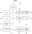
- FIG. 1 is a block diagram illustrating a configuration example of a printer 200.
- the printer 200 includes a processor 201, a ROM 202, a RAM 203, an operation panel 204, a communication interface 205, a conveyance motor 206, a motor drive circuit 207, a pump 208, a pump drive circuit 209, an ink jet head 100, and the like.
- the ink jet head 100 includes a head drive circuit 101 (control unit), a channel group 102, and the like.
- the printer 200 includes a bus line 211 such as an address bus and a data bus.
- the processor 201 is connected to the ROM 202, the RAM 203, the operation panel 204, the communication interface 205, the motor drive circuit 207, the pump drive circuit 209, and the head drive circuit 101 via the bus line 211, either directly or via an input and output circuit.
- the motor drive circuit 207 is connected to the conveyance motor 206.
- the pump drive circuit 209 is connected to the pump 208.
- the head drive circuit 101 is connected to the channel group 102.
- the printer 200 may further include a configuration as required in addition to the configuration as illustrated in FIG. 1 , or a specific configuration may be excluded from the printer 200.
- the processor 201 has a function of controlling an operation of the entire printer 200.
- the processor 201 may include an internal cache, various interfaces, and the like.
- the processor 201 realizes various processes by executing a program stored in advance in the internal cache or ROM 202.
- the processor 201 realizes various functions as the printer 200 according to an operating system, an application program, and the like.
- Some of the various functions realized by the processor 201 executing the program may be realized by a hardware circuit.
- the processor 201 controls the functions executed by the hardware circuit.
- the ROM 202 is a non-volatile memory in which a control program, control data, and the like are stored in advance.
- the control program and control data stored in the ROM 202 are preliminarily incorporated according to specifications of the printer 200.
- the ROM 202 stores the operating system, the application program, and the like.
- the RAM 203 is a volatile memory.
- the RAM 203 temporarily stores data and the like being processed by the processor 201.
- the RAM 203 stores various application programs and the like based on instructions from the processor 201.
- the RAM 203 may store data necessary for executing the application program, an execution result of the application program, and the like.
- the RAM 203 may function as an image memory in which print data is loaded.
- the operation panel 204 is an interface that receives input of an instruction from an operator and displays various information to the operator.
- the operation panel 204 is configured with an operation unit that receives input of an instruction and a display unit that displays information.
- the operation panel 204 transmits a signal indicating an operation received from the operator to the processor 201, as an operation of the operation unit.
- the operation unit is one on which function keys such as a power key, a paper feed key, and an error release key are disposed.
- the operation panel 204 displays various information based on control of the processor 201, as an operation of the display unit.
- the operation panel 204 displays a state of the printer 200 and the like.
- the display unit is configured with a liquid crystal monitor.
- the operation unit may be configured with a touch panel.
- the display unit may be integrally formed with the touch panel as the operation unit.
- the communication interface 205 is an interface for transmitting and receiving data to and from an external device via a network such as a local area network (LAN) .
- LAN local area network
- the communication interface 205 is an interface that supports LAN connection.
- the communication interface 205 receives print data from a client terminal via a network. For example, if an error occurs in the printer 200, the communication interface 205 transmits a signal notifying the error to the client terminal.
- the motor drive circuit 207 controls driving of the conveyance motor 206 according to a signal from the processor 201. For example, the motor drive circuit 207 transmits power or a control signal to the conveyance motor 206.
- the conveyance motor 206 functions as a drive source for a conveyance mechanism that conveys a medium such as paper based on the control of the motor drive circuit 207. If the conveyance motor 206 is driven, the conveyance mechanism conveys the medium. The conveyance mechanism conveys the medium to a printing position by the ink jet head 100. The conveyance mechanism discharges the printed medium to the outside of the printer 200 from a discharge port (not illustrated).
- the motor drive circuit 207 and the conveyance motor 206 configure the conveyance mechanism for conveying the medium.
- the pump drive circuit 209 controls driving of the pump 208. If the pump 208 is driven, ink is supplied from an ink tank to the ink jet head 100.
- the ink jet head 100 ejects an ink droplet (liquid droplet) onto the medium based on print data.
- the ink jet head 100 includes the head drive circuit 101, the channel group 102, and the like.
- a share mode type ink jet head 100 (see FIG. 2 ) is illustratively described.
- the ink jet head 100 will be described as one that ejects ink onto paper.
- the medium onto which the ink jet head 100 ejects ink is not limited to a specific configuration.
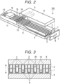
- FIG. 2 is a perspective view illustrating a part of the ink jet head 100 in an exploded manner.
- FIG. 3 is a cross-sectional view of the ink jet head 100.
- FIG. 4 is a longitudinal-sectional view of the ink jet head 100.
- the ink jet head 100 includes a base substrate 9.
- a first piezoelectric member 1 is joined to an upper surface of the base substrate 9, and a second piezoelectric member 2 is joined onto the first piezoelectric member 1.
- the joined first piezoelectric member 1 and second piezoelectric member 2 are polarized in directions opposite to each other along a plate thickness direction, as illustrated by the arrows in FIG. 3 .
- the base substrate 9 is formed by using a material having a small dielectric constant and a small difference in thermal expansion coefficient from that of the first piezoelectric member 1 and the second piezoelectric member 2.
- alumina Al203
- silicon nitride Si3N4
- silicon carbide SiC
- aluminum nitride AlN
- lead zirconate titanate PZT
- As the material of the first piezoelectric member 1 and the second piezoelectric member 2 lead zirconate titanate (PZT), lithium niobate (LiNbO3), lithium tantalate (LiTaO3), or the like is used.
- the ink jet head 100 is provided with a large number of long grooves 3 from the tip end side toward the rear end side of the joined first piezoelectric member 1 and second piezoelectric member 2.
- the grooves 3 are at regular intervals and parallel.
- the tip end of each groove 3 is open, and the rear end is inclined upward.
- the ink jet head 100 is provided with electrodes 4 on side walls and a bottom surface of each groove 3.
- the electrode 4 has a two-layer structure of nickel (Ni) and gold (Au).
- the electrode 4 is uniformly formed in each groove 3 by, for example, a plating method.
- a method for forming the electrode 4 is not limited to the plating method.
- a sputtering method, a vapor deposition method, or the like can also be used.
- the ink jet head 100 is provided with a lead-out electrode 10 from the rear end of each groove 3 toward a rear upper surface of the second piezoelectric member 2.
- the lead-out electrode 10 extends from the electrode 4.
- the ink jet head 100 includes a top plate 6 and an orifice plate 7.
- the top plate 6 closes the upper part of each groove 3.
- the orifice plate 7 closes the tip end of each groove 3.
- a plurality of pressure chambers 15 are formed by the grooves 3 surrounded by the top plate 6 and the orifice plate 7.
- the pressure chamber 15 is filled with ink supplied from the ink tank.
- the pressure chambers 15, each have a shape having, for example, a depth of 300 ⁇ m and a width of 80 ⁇ m, and are arranged in parallel at a pitch of 169 ⁇ m.
- Such a pressure chamber 15 is also referred to as an ink chamber.
- the top plate 6 includes a common ink chamber 5 on the inside rear side thereof.
- the orifice plate 7 is provided with a nozzle 8 at a position facing each groove 3.
- the nozzle 8 communicates with the facing groove 3, that is, the pressure chamber 15.
- the nozzle 8 has a tapered shape from the pressure chamber 15 side toward an ink ejection side on the opposite side.
- the nozzles 8 are formed to be displaced at regular intervals in the height direction of the groove 3 (vertical direction of the paper surface in FIG. 3 ) by forming the nozzles 8 corresponding to three adjacent pressure chambers 15 as one set.
- a meniscus 20 of ink is formed in the nozzle 8.
- the meniscus 20 is formed along the inner walls of the nozzle 8.
- the first piezoelectric member 1 and the second piezoelectric member 2 configuring a partition wall of the pressure chamber 15 are sandwiched by the electrodes 4 provided in the pressure chamber 15 to form actuators 16 for driving the pressure chamber 15.
- a printed circuit board 11 on which conductive patterns 13 are formed is joined to the upper surface on the rear side of the base substrate 9.
- a drive IC 12 on which the head drive circuit 101 is mounted is installed on the printed circuit board 11.
- the drive IC 12 is connected to the conductive pattern 13.
- the conductive pattern 13 is bonded to each of the lead-out electrodes 10 by wire bonding with a conducting wire 14.
- a set of the pressure chamber 15, the electrode 4, and the nozzle 8 included in the ink jet head 100 is referred to as a channel. That is, the ink jet head 100 includes channels of ch.1, ch.2, ..., ch.N as many as the number N of the grooves 3.
- FIG. 5 is a block diagram for describing a configuration example of the head drive circuit 101. As described above, the head drive circuit 101 is disposed in the drive IC 12.
- the head drive circuit 101 drives the channel group 102 of the ink jet head 100 based on the print data.
- the channel group 102 is configured with a plurality of channels of ch.1, ch.2, ..., ch.N including the pressure chambers 15, the actuators 16, the electrodes 4, the nozzles 8, and the like. That is, the channel group 102 ejects ink droplets by the operation of each pressure chamber 15 expanded and contracted by the actuators 16 based on a control signal from the head drive circuit 101.
- the head drive circuit 101 includes a pattern generator 301, a frequency setting unit 302, a drive signal generation unit 303, a switch circuit 304, and the like.
- the pattern generator 301 generates various waveform patterns using a waveform pattern of an expansion pulse for expanding a volume of the pressure chamber 15, a release period during which the volume of the pressure chamber 15 is released, a waveform pattern of a contraction pulse for contracting the volume of the pressure chamber 15, and the like.
- the pattern generator 301 generates a waveform pattern of an ejection pulse for ejecting one ink droplet.
- the period of the ejection pulse is a section for ejecting one ink droplet, a so-called one-drop cycle.
- the ejection pulse will be described in detail later.
- the frequency setting unit 302 sets a drive frequency of the ink jet head 100.
- the drive frequency is a frequency of a drive pulse generated by the drive signal generation unit 303 .
- the head drive circuit 101 operates according to the drive pulse.
- the drive signal generation unit 303 generates a pulse for each channel based on the waveform pattern generated by the pattern generator 301 and the drive frequency set by the frequency setting unit 302, according to the print data input from the bus line.
- the pulse for each channel is output from the drive signal generation unit 303 to the switch circuit 304.
- the switch circuit 304 switches a voltage to be applied to the electrode 4 of each channel according to the pulse for each channel output from the drive signal generation unit 303. That is, the switch circuit 304 applies a voltage to the actuator 16 of each channel based on the energization time of the expansion pulse or the like set by the pattern generator 301.
- the switch circuit 304 expands or contracts the volume of the pressure chamber 15 of each channel by switching this voltage, and ejects ink droplets from the nozzle 8 of each channel by the number of gradations.
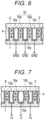
- FIG. 6 illustrates a state of the pressure chamber 15b during the release period.
- a partition wall 16a and a partition wall 16b configure the actuator 16.
- the head drive circuit 101 sets all the potentials of the electrodes 4 arranged respectively on the partition walls 16a and 16b of the pressure chamber 15b and the pressure chambers 15a and 15c on both adjacent sides of the pressure chamber 15b to a ground potential GND.
- the partition wall 16a sandwiched between the pressure chamber 15a and the pressure chamber 15b and the partition wall 16b sandwiched between the pressure chamber 15b and the pressure chamber 15c do not cause any distortion.
- FIG. 7 illustrates an example of a state in which the head drive circuit 101 applies an expansion pulse to the actuator 16 of the pressure chamber 15b.
- the head drive circuit 101 applies a negative voltage -V to the electrode 4 of the central pressure chamber 15b, and applies a voltage +V to the electrodes 4 of the pressure chambers 15a and 15c on both adjacent sides of the pressure chamber 15b.
- an electric field having a voltage of 2 V acts on the partition walls 16a and 16b in a direction orthogonal to the polarization direction of the first piezoelectric member 1 and the second piezoelectric member 2.
- the partition walls 16a and 16b are respectively deformed outward so as to expand the volume of the pressure chamber 15b.
- FIG. 8 illustrates an example of a state in which the head drive circuit 101 applies a first contraction pulse to the actuator 16 of the pressure chamber 15b.
- the head drive circuit 101 sets the electrode 4 of the central pressure chamber 15b to the ground potential GND, and applies a voltage -V to the electrodes 4 of the pressure chambers 15a and 15c on both adjacent sides of the central pressure chamber 15b.
- an electric field having a voltage of V acts on each of the partition walls 16a and 16b in a direction opposite to that in the state of FIG. 7 .
- the partition walls 16a and 16b are respectively deformed inward so as to contract the volume of the pressure chamber 15b.
- the first contraction pulse causes the pressure chamber 15b to contract to a first volume smaller than the original volume.
- the head drive circuit 101 may apply a voltage +V to the electrode 4 of the central pressure chamber 15b as the first contraction pulse, and set the electrodes 4 of the pressure chambers 15a and 15c on both adjacent sides to the ground potential GND.
- FIG. 9 illustrates an example of a state in which the head drive circuit 101 applies a second contraction pulse to the actuator 16 of the pressure chamber 15b.
- the head drive circuit 101 applies a positive voltage +V to the electrode 4 of the central pressure chamber 15b, and applies a voltage -V to the electrodes 4 of the pressure chambers 15a and 15c on both adjacent sides .
- an electric field having a voltage of 2 V acts on each of the partition walls 16a and 16b in the direction opposite to that in the state illustrated in FIG. 7 .
- the partition walls 16a and 16b are respectively deformed inward so as to contract the volume of the pressure chamber 15b.
- the second contraction pulse causes the pressure chamber 15b to contract to a second volume smaller than the first volume.
- pressure vibration is generated in the pressure chamber 15b. Due to this pressure vibration, the pressure in the pressure chamber 15b increases, and the ink droplet is ejected from the nozzle 8 communicating with the pressure chamber 15b.
- the partition walls 16a and 16b that separate the pressure chambers 15a, 15b, and 15c serve as the actuator 16 for applying pressure vibration to the inside of the pressure chamber 15b having the partition walls 16a and 16b as wall surfaces. That is, the pressure chamber 15 is expanded or contracted by the operation of the actuator 16.
- the pressure chambers 15 respectively share the actuator 16 (partition walls) with adjacent pressure chambers 15. Therefore, the head drive circuit 101 cannot drive the pressure chambers 15 individually.
- the head drive circuit 101 drives the pressure chambers 15 by dividing the pressure chambers 15 into (n + 1) groups at intervals of n pressure chambers (n is an integer of 2 or more) .
- n is an integer of 2 or more
- a case where the head drive circuit 101 drives the pressure chambers 15 by dividing the pressure chambers 15 into three groups at intervals of two chambers that is, a case of a so-called 3-split drive is illustrated.
- the 3-split drive is just an example, and may be a 4-split drive or a 5-split drive.
- the head drive circuit 101 ejects the ink droplet from each channel of the channel group 102 based on the signal from the processor 201. That is, the head drive circuit 101 applies an ejection pulse to the actuator 16 configuring channels (part or all) of the channel group 102 based on the signal from the processor 201.
- the head drive circuit 101 applies the ejection pulse to the actuator 16 to eject a predetermined amount of ink droplets from the nozzle 8.
- FIG. 10 illustrates a configuration example of the ejection pulse.
- a graph 51 illustrates a voltage applied to the actuator 16 by the head drive circuit 101.
- a graph 52 illustrates pressure generated in the pressure chamber 15.
- a graph 53 illustrates a flow velocity of a meniscus 20. In the graph 53, a negative value indicates that the meniscus 20 is progressing inside the pressure chamber 15, and a positive value indicates that the meniscus 20 is progressing outside the pressure chamber.
- the horizontal axis represents time.
- the ejection pulse is composed of an expansion pulse, a first contraction pulse, and a second contraction pulse.
- the flow velocity becomes zero three times.
- the flow velocity becomes zero for the first time.
- the flow velocity changes from negative to zero and turns positive. That is, at the time point 81, the meniscus 20 changes from a state of progressing inside the pressure chamber 15 to a state of progressing outside thereof.
- the flow velocity becomes zero for the second time.
- the flow velocity changes from positive to zero and turns negative. That is, at the time point 82, the meniscus 20 changes from the state of progressing outside the pressure chamber 15 to the state of progressing inside thereof.
- the flow velocity becomes zero for the third time.
- the flow velocity changes from negative to zero and turns positive. That is, at the time point 83, the meniscus 20 changes from the state of progressing inside the pressure chamber 15 to the state of progressing outside thereof.
- the head drive circuit 101 applies the expansion pulse to the actuator 16.
- the head drive circuit 101 applies an expansion pulse having a width of AL (half the natural vibration period of pressure in the pressure chamber 15).
- a peak value (voltage) of the expansion pulse is 2 V.
- V is a predetermined value.
- the pressure chamber 15 is expanded by the expansion pulse. That is, the pressure chamber is in the state illustrated in FIG. 7 . In this state, the pressure in the pressure chamber 15 decreases, and ink is supplied to the pressure chamber 15 from the common ink chamber 5.
- the flow velocity decreases from the start time point of the expansion pulse, reaches the bottom, and increases.
- the flow velocity continues to increase and becomes zero at the time point 81.
- the head drive circuit 101 applies the first contraction pulse after applying the expansion pulse.
- the head drive circuit 101 applies a first contraction pulse having a width of the AL.
- the peak value (voltage) of the first contraction pulse is V.
- the pressure chamber 15 contracts to a first volume due to the first contraction pulse. That is, the pressure chamber is in the state illustrated in FIG. 8 . In this state, the pressure in the pressure chamber 15 increases. As the pressure in the pressure chamber 15 increases, the velocity of the meniscus 20 formed in the nozzle 8 exceeds a threshold at which the ink droplet is ejected. At the timing when the velocity of the meniscus 20 exceeds the threshold, the ink droplet is ejected from the nozzle 8 of the pressure chamber 15.
- the flow velocity reaches the peak of the flow velocity and decreases.
- the head drive circuit 101 applies the second contraction pulse after applying the first contraction pulse.
- the head drive circuit 101 applies a second contraction pulse having a width including the time point 83. That is, the second contraction pulse includes the time point when the flow velocity becomes zero for the third time.
- the width of the second contraction pulse is longer than the AL.
- the peak value (voltage) of the second contraction pulse is 2 V.
- the pressure chamber 15 contracts to a second volume due to the second contraction pulse. That is, the pressure chamber is in the state illustrated in FIG. 9 . In this state, the flow velocity continues to decrease and passes the time point 82. The flow velocity reaches the bottom and increases again. The flow velocity becomes zero at the time point 83 and then increases.
- the second contraction pulse ends before the flow velocity reaches the peak of the flow velocity. That is, the period between the time point 83 and the end time point of the second contraction pulse is less than or equal to half of the AL (a quarter of the natural vibration period).
- the pressure chamber 15 continues to contract even after the time point 83 due to the second contraction pulse, and thus the vibration of the flow velocity and the pressure continues even after the head drive circuit 101 applies the ejection pulse.
- FIG. 11 illustrates another configuration example of the ejection pulse.
- a graph 61 illustrates a voltage applied to the actuator 16 by the head drive circuit 101.
- a graph 62 illustrates pressure generated in the pressure chamber 15.
- a graph 63 illustrates a flow velocity of a meniscus 20. The horizontal axis represents time.
- the ejection pulse is composed of an expansion pulse, a first contraction pulse, and a second contraction pulse.
- the flow velocity becomes zero three times.
- the flow velocity becomes zero for the first time.
- the flow velocity changes from negative to zero and turns positive. That is, at the time point 91, the meniscus 20 changes from a state of progressing inside the pressure chamber 15 to a state of progressing outside thereof.
- the flow velocity becomes zero for the second time.
- the flow velocity changes from positive to zero and turns negative. That is, at the time point 92, the meniscus 20 changes from the state of progressing outside the pressure chamber 15 to the state of progressing inside thereof.
- the flow velocity becomes zero for the third time.
- the flow velocity changes from negative to zero and turns positive. That is, at the time point 93, the meniscus 20 changes from the state of progressing inside the pressure chamber 15 to the state of progressing outside thereof.
- the head drive circuit 101 applies the expansion pulse to the actuator 16.
- the head drive circuit 101 applies an expansion pulse having a width of the AL.
- the peak value (voltage) of the expansion pulse is 2 V.
- the pressure chamber 15 expands due to the expansion pulse. That is, the pressure chamber is in the state illustrated in FIG. 7 . In this state, the pressure in the pressure chamber 15 decreases, and ink is supplied to the pressure chamber 15 from the common ink chamber 5.
- the flow velocity decreases from the start time point of the expansion pulse, reaches the bottom, and increases.
- the flow velocity continues to increase and becomes zero at the time point 91.
- the head drive circuit 101 applies the first contraction pulse after applying the expansion pulse.
- the head drive circuit 101 applies a first contraction pulse having a width including the time point 92. That is, the first contraction pulse includes the time point when the flow velocity becomes zero for the second time.
- the width of the first contraction pulse is longer than the AL.
- the peak value (voltage) of the first contraction pulse is V.
- the pressure chamber 15 contracts to the first volume due to the first contraction pulse. That is, the pressure chamber is in the state illustrated in FIG. 8 . In this state, the pressure in the pressure chamber 15 increases. The pressure in the pressure chamber 15 increases, and thus the velocity of the meniscus 20 formed in the nozzle 8 exceeds the threshold at which the ink droplet is ejected. At the timing when the velocity of the meniscus 20 exceeds the ejection threshold, ejection of the ink droplet is started from the nozzle 8 of the pressure chamber 15.
- the flow velocity reaches the peak of the flow velocity and decreases.
- the flow velocity continues to decrease and passes the time point 92.
- the flow velocity reaches the bottom and increases again.
- the head drive circuit 101 applies the second contraction pulse after applying the first contraction pulse.
- the head drive circuit 101 applies a second contraction pulse having a width including the time point 93.
- the second contraction pulse includes the time point when the flow velocity becomes zero for the third time.
- the width of the second contraction pulse is the AL.
- the peak value (voltage) of the second contraction pulse is 2 V.
- the pressure chamber 15 contracts to the second volume due to the second contraction pulse. That is, the pressure chamber is in the state illustrated in FIG. 9 . In this state, the flow velocity continues to increase and becomes zero at the time point 93. After that, the flow velocity continues to increase.
- the second contraction pulse ends before pressure in the pressure chamber 15 reaches the peak of the pressure. That is, the period between the time point 93 and the end time point of the second contraction pulse is less than or equal to half of the AL.
- the pressure chamber 15 continues to contract after the time point 83 due to the second contraction pulse, and thus the vibration of the flow velocity and the pressure continues even after the head drive circuit 101 applies the ejection pulse.
- the ink jet head may be a circulation type head.
- the peak value of the second contraction pulse may not be twice the peak value of the first contraction pulse.
- the peak value of the expansion pulse may not be the same as the peak value of the second contraction pulse.
- the ejection pulse which includes the second contraction pulse formed so as to include the time point when the flow velocity of the meniscus changes from negative to positive, is applied to the actuator.
- the ink jet head can maintain the vibration of the flow velocity even after applying the ejection pulse. Therefore, the ink jet head can push out the ink droplet extending in the flight direction from the nozzle.
- the ink jet head can prevent the ink droplet from flying in an extended state. Accordingly, the ink jet head can prevent satellite dots, mists, and the like to prevent deterioration of print quality.
- the ink jet head applies an ejection pulse, which includes the first contraction pulse and the second contraction pulse formed so as to include the time point when the flow velocity of the meniscus changes from positive to negative, to the actuator.
- an ejection pulse which includes the first contraction pulse and the second contraction pulse formed so as to include the time point when the flow velocity of the meniscus changes from positive to negative, to the actuator.
- the ink jet head can increase the vibration of the flow velocity after applying the ejection pulse. Therefore, the ink jet head can more effectively prevent satellite dots, mists, and the like.
- the second contraction pulse does not include the peak of the flow velocity.
- the ink jet head prevents the flow velocity vibration from becoming too large. Therefore, the ink jet head can prevent unnecessary ink from being ejected after applying the ejection pulse.
Landscapes
- Particle Formation And Scattering Control In Inkjet Printers (AREA)
Claims (4)
- Flüssigkeitsausstoßkopf (100), umfassend:einen Aktuator (16), der konfiguriert ist, um eine Druckkammer zu expandieren oder zu kontrahieren, die mit einer Düse in Verbindung ist, die konfiguriert ist, um Tinte auszustoßen;eine Steuereinheit (101), die konfiguriert ist, um einen Expansionsimpuls zum Expandieren der Druckkammer an den Aktuator anzulegen und dann einen ersten Kontraktionsimpuls zum Kontrahieren der Druckkammer auf ein erstes Volumen an das Stellglied anzulegen und dann einen zweiten Kontraktionsimpuls zum Kontrahieren eines Volumens der Druckkammer auf ein zweites Volumen, das kleiner ist als das erste Volumen, an den Aktuator anzulegen, wobeieine Breite des zweiten Kontraktionsimpulses einen ersten Zeitpunkt beinhaltet, an dem nach einem Wechsel von dem ersten Kontraktionsimpuls zu dem zweiten Kontraktionsimpuls ein in der Düse gebildeter Meniskus von einem Zustand eines Fortschreitens innerhalb der Druckkammer zu einem Zustand eines Fortschreitens außerhalb der Druckkammer wechselt,dadurch gekennzeichnet, dass ein Zeitraum zwischen dem ersten Zeitpunkt und einem Endzeitpunkt des zweiten Kontraktionsimpulses gleich wie oder kleiner als ein Viertel einer natürlichen Schwingungsperiode des Drucks in der Druckkammer ist.
- Flüssigkeitsausstoßkopf nach Anspruch 1, wobei der erste Zeitpunkt ein Zeitpunkt ist, an dem eine Strömungsgeschwindigkeit des Meniskus zum dritten Mal nach Anlegen des Expansionsimpulses durch die Steuereinheit Null wird.
- Flüssigkeitsausstoßkopf nach Anspruch 1 oder 2, wobei
der erste Kontraktionsimpuls eine Breite aufweist, die einen zweiten Zeitpunkt beinhaltet, an dem der Meniskus von dem Zustand eines Fortschreitens außerhalb der Druckkammer in den Zustand eines Fortschreitens innerhalb der Druckkammer wechselt. - Drucker (200), der konfiguriert ist, um ein Flüssigkeitströpfchen auf ein Medium auszustoßen, umfassend:einen Fördermechanismus, der konfiguriert ist, um das Medium zu fördern; undden Flüssigkeitsausstoßkopf nach einem der Ansprüche 1 bis 3.
Applications Claiming Priority (1)
| Application Number | Priority Date | Filing Date | Title |
|---|---|---|---|
| JP2020109970A JP7458914B2 (ja) | 2020-06-25 | 2020-06-25 | 液体吐出ヘッド及びプリンタ |
Publications (2)
| Publication Number | Publication Date |
|---|---|
| EP3928989A1 EP3928989A1 (de) | 2021-12-29 |
| EP3928989B1 true EP3928989B1 (de) | 2024-06-12 |
Family
ID=73726538
Family Applications (1)
| Application Number | Title | Priority Date | Filing Date |
|---|---|---|---|
| EP20209865.3A Active EP3928989B1 (de) | 2020-06-25 | 2020-11-25 | Flüssigkeitsausstosskopf und drucker |
Country Status (3)
| Country | Link |
|---|---|
| EP (1) | EP3928989B1 (de) |
| JP (1) | JP7458914B2 (de) |
| CN (1) | CN113844175B (de) |
Families Citing this family (1)
| Publication number | Priority date | Publication date | Assignee | Title |
|---|---|---|---|---|
| JP2025173828A (ja) * | 2024-05-15 | 2025-11-28 | 理想テクノロジーズ株式会社 | 駆動装置 |
Family Cites Families (10)
| Publication number | Priority date | Publication date | Assignee | Title |
|---|---|---|---|---|
| JP2010158843A (ja) * | 2009-01-08 | 2010-07-22 | Seiko Epson Corp | 液体吐出装置、及び、その制御方法 |
| JP2011020280A (ja) * | 2009-07-13 | 2011-02-03 | Seiko Epson Corp | 液体吐出装置、及び、その制御方法 |
| JP2011177963A (ja) * | 2010-02-26 | 2011-09-15 | Seiko Epson Corp | 液体吐出装置、及び、液体吐出装置の制御方法 |
| JP5871851B2 (ja) * | 2013-04-16 | 2016-03-01 | 株式会社東芝 | インクジェットヘッドの駆動方法及び駆動装置 |
| JP6264971B2 (ja) * | 2014-03-17 | 2018-01-24 | 株式会社リコー | 液滴吐出装置、画像形成装置、及び液滴吐出装置の制御方法 |
| JPWO2017130695A1 (ja) * | 2016-01-29 | 2018-11-15 | コニカミノルタ株式会社 | インクジェット駆動装置およびインクジェット駆動方法 |
| JP2018161750A (ja) * | 2017-03-24 | 2018-10-18 | 東芝テック株式会社 | インクジェットヘッド、インクジェット記録装置及び吐出方法 |
| JP6976726B2 (ja) * | 2017-06-06 | 2021-12-08 | 東芝テック株式会社 | 駆動装置及びインクジェット記録装置 |
| JP6987580B2 (ja) * | 2017-09-22 | 2022-01-05 | 東芝テック株式会社 | 波形生成装置及びインクジェット記録装置 |
| JP2019119175A (ja) * | 2018-01-10 | 2019-07-22 | 東芝テック株式会社 | 液体吐出ヘッド及びプリンタ |
-
2020
- 2020-06-25 JP JP2020109970A patent/JP7458914B2/ja active Active
- 2020-11-25 EP EP20209865.3A patent/EP3928989B1/de active Active
-
2021
- 2021-03-04 CN CN202110241456.7A patent/CN113844175B/zh active Active
Also Published As
| Publication number | Publication date |
|---|---|
| EP3928989A1 (de) | 2021-12-29 |
| JP2022007186A (ja) | 2022-01-13 |
| JP7458914B2 (ja) | 2024-04-01 |
| CN113844175B (zh) | 2023-09-19 |
| CN113844175A (zh) | 2021-12-28 |
Similar Documents
| Publication | Publication Date | Title |
|---|---|---|
| EP3702159B1 (de) | Flüssigkeitsausstosskopf und drucker | |
| JP4866457B2 (ja) | インクジェット記録装置、クロストーク低減方法 | |
| US20180264810A1 (en) | Ink jet head and ink jet recording apparatus | |
| JP2015085593A (ja) | インクジェットヘッド | |
| JP2000141647A (ja) | インクジェット記録装置 | |
| US10710364B2 (en) | Liquid discharge head and printer | |
| JP6450533B2 (ja) | インクジェットヘッド及びインクジェットプリンタ | |
| US20180272698A1 (en) | Inkjet head, inkjet recording apparatus, and discharging method | |
| EP3928989A1 (de) | Flüssigkeitsausstosskopf und drucker | |
| CN110978794B (zh) | 液体喷头以及打印机 | |
| US11059285B2 (en) | Liquid discharge head and printer | |
| JP7242940B2 (ja) | 液体吐出ヘッド及びプリンタ | |
| JP7510830B2 (ja) | 液滴吐出ヘッド及びプリンタ | |
| JP2020192690A (ja) | 液体吐出ヘッド及びプリンタ | |
| JP2020196207A (ja) | 液体吐出ヘッド及びプリンタ |
Legal Events
| Date | Code | Title | Description |
|---|---|---|---|
| PUAI | Public reference made under article 153(3) epc to a published international application that has entered the european phase |
Free format text: ORIGINAL CODE: 0009012 |
|
| STAA | Information on the status of an ep patent application or granted ep patent |
Free format text: STATUS: THE APPLICATION HAS BEEN PUBLISHED |
|
| AK | Designated contracting states |
Kind code of ref document: A1 Designated state(s): AL AT BE BG CH CY CZ DE DK EE ES FI FR GB GR HR HU IE IS IT LI LT LU LV MC MK MT NL NO PL PT RO RS SE SI SK SM TR |
|
| B565 | Issuance of search results under rule 164(2) epc |
Effective date: 20210430 |
|
| STAA | Information on the status of an ep patent application or granted ep patent |
Free format text: STATUS: REQUEST FOR EXAMINATION WAS MADE |
|
| 17P | Request for examination filed |
Effective date: 20220629 |
|
| RBV | Designated contracting states (corrected) |
Designated state(s): AL AT BE BG CH CY CZ DE DK EE ES FI FR GB GR HR HU IE IS IT LI LT LU LV MC MK MT NL NO PL PT RO RS SE SI SK SM TR |
|
| GRAP | Despatch of communication of intention to grant a patent |
Free format text: ORIGINAL CODE: EPIDOSNIGR1 |
|
| STAA | Information on the status of an ep patent application or granted ep patent |
Free format text: STATUS: GRANT OF PATENT IS INTENDED |
|
| INTG | Intention to grant announced |
Effective date: 20240108 |
|
| GRAS | Grant fee paid |
Free format text: ORIGINAL CODE: EPIDOSNIGR3 |
|
| GRAA | (expected) grant |
Free format text: ORIGINAL CODE: 0009210 |
|
| STAA | Information on the status of an ep patent application or granted ep patent |
Free format text: STATUS: THE PATENT HAS BEEN GRANTED |
|
| AK | Designated contracting states |
Kind code of ref document: B1 Designated state(s): AL AT BE BG CH CY CZ DE DK EE ES FI FR GB GR HR HU IE IS IT LI LT LU LV MC MK MT NL NO PL PT RO RS SE SI SK SM TR |
|
| REG | Reference to a national code |
Ref country code: GB Ref legal event code: FG4D |
|
| REG | Reference to a national code |
Ref country code: CH Ref legal event code: EP |
|
| REG | Reference to a national code |
Ref country code: IE Ref legal event code: FG4D |
|
| REG | Reference to a national code |
Ref country code: DE Ref legal event code: R096 Ref document number: 602020032238 Country of ref document: DE |
|
| REG | Reference to a national code |
Ref country code: DE Ref legal event code: R081 Ref document number: 602020032238 Country of ref document: DE Owner name: RISO TECHNOLOGIES CORP., JP Free format text: FORMER OWNER: TOSHIBA TEC KABUSHIKI KAISHA, TOKYO, JP |
|
| PG25 | Lapsed in a contracting state [announced via postgrant information from national office to epo] |
Ref country code: BG Free format text: LAPSE BECAUSE OF FAILURE TO SUBMIT A TRANSLATION OF THE DESCRIPTION OR TO PAY THE FEE WITHIN THE PRESCRIBED TIME-LIMIT Effective date: 20240612 |
|
| RAP2 | Party data changed (patent owner data changed or rights of a patent transferred) |
Owner name: RISO TECHNOLOGIES CORPORATION |
|
| PG25 | Lapsed in a contracting state [announced via postgrant information from national office to epo] |
Ref country code: FI Free format text: LAPSE BECAUSE OF FAILURE TO SUBMIT A TRANSLATION OF THE DESCRIPTION OR TO PAY THE FEE WITHIN THE PRESCRIBED TIME-LIMIT Effective date: 20240612 Ref country code: HR Free format text: LAPSE BECAUSE OF FAILURE TO SUBMIT A TRANSLATION OF THE DESCRIPTION OR TO PAY THE FEE WITHIN THE PRESCRIBED TIME-LIMIT Effective date: 20240612 |
|
| REG | Reference to a national code |
Ref country code: LT Ref legal event code: MG9D |
|
| PG25 | Lapsed in a contracting state [announced via postgrant information from national office to epo] |
Ref country code: GR Free format text: LAPSE BECAUSE OF FAILURE TO SUBMIT A TRANSLATION OF THE DESCRIPTION OR TO PAY THE FEE WITHIN THE PRESCRIBED TIME-LIMIT Effective date: 20240913 |
|
| REG | Reference to a national code |
Ref country code: NL Ref legal event code: MP Effective date: 20240612 |
|
| PG25 | Lapsed in a contracting state [announced via postgrant information from national office to epo] |
Ref country code: ES Free format text: LAPSE BECAUSE OF FAILURE TO SUBMIT A TRANSLATION OF THE DESCRIPTION OR TO PAY THE FEE WITHIN THE PRESCRIBED TIME-LIMIT Effective date: 20240612 |
|
| REG | Reference to a national code |
Ref country code: GB Ref legal event code: 732E Free format text: REGISTERED BETWEEN 20240926 AND 20241002 |
|
| PG25 | Lapsed in a contracting state [announced via postgrant information from national office to epo] |
Ref country code: LV Free format text: LAPSE BECAUSE OF FAILURE TO SUBMIT A TRANSLATION OF THE DESCRIPTION OR TO PAY THE FEE WITHIN THE PRESCRIBED TIME-LIMIT Effective date: 20240612 |
|
| PG25 | Lapsed in a contracting state [announced via postgrant information from national office to epo] |
Ref country code: NO Free format text: LAPSE BECAUSE OF FAILURE TO SUBMIT A TRANSLATION OF THE DESCRIPTION OR TO PAY THE FEE WITHIN THE PRESCRIBED TIME-LIMIT Effective date: 20240912 Ref country code: LV Free format text: LAPSE BECAUSE OF FAILURE TO SUBMIT A TRANSLATION OF THE DESCRIPTION OR TO PAY THE FEE WITHIN THE PRESCRIBED TIME-LIMIT Effective date: 20240612 Ref country code: HR Free format text: LAPSE BECAUSE OF FAILURE TO SUBMIT A TRANSLATION OF THE DESCRIPTION OR TO PAY THE FEE WITHIN THE PRESCRIBED TIME-LIMIT Effective date: 20240612 Ref country code: GR Free format text: LAPSE BECAUSE OF FAILURE TO SUBMIT A TRANSLATION OF THE DESCRIPTION OR TO PAY THE FEE WITHIN THE PRESCRIBED TIME-LIMIT Effective date: 20240913 Ref country code: FI Free format text: LAPSE BECAUSE OF FAILURE TO SUBMIT A TRANSLATION OF THE DESCRIPTION OR TO PAY THE FEE WITHIN THE PRESCRIBED TIME-LIMIT Effective date: 20240612 Ref country code: ES Free format text: LAPSE BECAUSE OF FAILURE TO SUBMIT A TRANSLATION OF THE DESCRIPTION OR TO PAY THE FEE WITHIN THE PRESCRIBED TIME-LIMIT Effective date: 20240612 Ref country code: BG Free format text: LAPSE BECAUSE OF FAILURE TO SUBMIT A TRANSLATION OF THE DESCRIPTION OR TO PAY THE FEE WITHIN THE PRESCRIBED TIME-LIMIT Effective date: 20240612 Ref country code: RS Free format text: LAPSE BECAUSE OF FAILURE TO SUBMIT A TRANSLATION OF THE DESCRIPTION OR TO PAY THE FEE WITHIN THE PRESCRIBED TIME-LIMIT Effective date: 20240912 |
|
| PG25 | Lapsed in a contracting state [announced via postgrant information from national office to epo] |
Ref country code: NL Free format text: LAPSE BECAUSE OF FAILURE TO SUBMIT A TRANSLATION OF THE DESCRIPTION OR TO PAY THE FEE WITHIN THE PRESCRIBED TIME-LIMIT Effective date: 20240612 |
|
| REG | Reference to a national code |
Ref country code: AT Ref legal event code: MK05 Ref document number: 1693906 Country of ref document: AT Kind code of ref document: T Effective date: 20240612 |
|
| PG25 | Lapsed in a contracting state [announced via postgrant information from national office to epo] |
Ref country code: NL Free format text: LAPSE BECAUSE OF FAILURE TO SUBMIT A TRANSLATION OF THE DESCRIPTION OR TO PAY THE FEE WITHIN THE PRESCRIBED TIME-LIMIT Effective date: 20240612 |
|
| PG25 | Lapsed in a contracting state [announced via postgrant information from national office to epo] |
Ref country code: PT Free format text: LAPSE BECAUSE OF FAILURE TO SUBMIT A TRANSLATION OF THE DESCRIPTION OR TO PAY THE FEE WITHIN THE PRESCRIBED TIME-LIMIT Effective date: 20241014 |
|
| PG25 | Lapsed in a contracting state [announced via postgrant information from national office to epo] |
Ref country code: PT Free format text: LAPSE BECAUSE OF FAILURE TO SUBMIT A TRANSLATION OF THE DESCRIPTION OR TO PAY THE FEE WITHIN THE PRESCRIBED TIME-LIMIT Effective date: 20241014 |
|
| PG25 | Lapsed in a contracting state [announced via postgrant information from national office to epo] |
Ref country code: PL Free format text: LAPSE BECAUSE OF FAILURE TO SUBMIT A TRANSLATION OF THE DESCRIPTION OR TO PAY THE FEE WITHIN THE PRESCRIBED TIME-LIMIT Effective date: 20240612 |
|
| PG25 | Lapsed in a contracting state [announced via postgrant information from national office to epo] |
Ref country code: EE Free format text: LAPSE BECAUSE OF FAILURE TO SUBMIT A TRANSLATION OF THE DESCRIPTION OR TO PAY THE FEE WITHIN THE PRESCRIBED TIME-LIMIT Effective date: 20240612 |
|
| PG25 | Lapsed in a contracting state [announced via postgrant information from national office to epo] |
Ref country code: AT Free format text: LAPSE BECAUSE OF FAILURE TO SUBMIT A TRANSLATION OF THE DESCRIPTION OR TO PAY THE FEE WITHIN THE PRESCRIBED TIME-LIMIT Effective date: 20240612 Ref country code: IS Free format text: LAPSE BECAUSE OF FAILURE TO SUBMIT A TRANSLATION OF THE DESCRIPTION OR TO PAY THE FEE WITHIN THE PRESCRIBED TIME-LIMIT Effective date: 20241012 |
|
| PG25 | Lapsed in a contracting state [announced via postgrant information from national office to epo] |
Ref country code: CZ Free format text: LAPSE BECAUSE OF FAILURE TO SUBMIT A TRANSLATION OF THE DESCRIPTION OR TO PAY THE FEE WITHIN THE PRESCRIBED TIME-LIMIT Effective date: 20240612 |
|
| PG25 | Lapsed in a contracting state [announced via postgrant information from national office to epo] |
Ref country code: SK Free format text: LAPSE BECAUSE OF FAILURE TO SUBMIT A TRANSLATION OF THE DESCRIPTION OR TO PAY THE FEE WITHIN THE PRESCRIBED TIME-LIMIT Effective date: 20240612 Ref country code: RO Free format text: LAPSE BECAUSE OF FAILURE TO SUBMIT A TRANSLATION OF THE DESCRIPTION OR TO PAY THE FEE WITHIN THE PRESCRIBED TIME-LIMIT Effective date: 20240612 |
|
| PG25 | Lapsed in a contracting state [announced via postgrant information from national office to epo] |
Ref country code: SM Free format text: LAPSE BECAUSE OF FAILURE TO SUBMIT A TRANSLATION OF THE DESCRIPTION OR TO PAY THE FEE WITHIN THE PRESCRIBED TIME-LIMIT Effective date: 20240612 |
|
| PG25 | Lapsed in a contracting state [announced via postgrant information from national office to epo] |
Ref country code: SM Free format text: LAPSE BECAUSE OF FAILURE TO SUBMIT A TRANSLATION OF THE DESCRIPTION OR TO PAY THE FEE WITHIN THE PRESCRIBED TIME-LIMIT Effective date: 20240612 Ref country code: SK Free format text: LAPSE BECAUSE OF FAILURE TO SUBMIT A TRANSLATION OF THE DESCRIPTION OR TO PAY THE FEE WITHIN THE PRESCRIBED TIME-LIMIT Effective date: 20240612 Ref country code: RO Free format text: LAPSE BECAUSE OF FAILURE TO SUBMIT A TRANSLATION OF THE DESCRIPTION OR TO PAY THE FEE WITHIN THE PRESCRIBED TIME-LIMIT Effective date: 20240612 Ref country code: PL Free format text: LAPSE BECAUSE OF FAILURE TO SUBMIT A TRANSLATION OF THE DESCRIPTION OR TO PAY THE FEE WITHIN THE PRESCRIBED TIME-LIMIT Effective date: 20240612 Ref country code: IS Free format text: LAPSE BECAUSE OF FAILURE TO SUBMIT A TRANSLATION OF THE DESCRIPTION OR TO PAY THE FEE WITHIN THE PRESCRIBED TIME-LIMIT Effective date: 20241012 Ref country code: EE Free format text: LAPSE BECAUSE OF FAILURE TO SUBMIT A TRANSLATION OF THE DESCRIPTION OR TO PAY THE FEE WITHIN THE PRESCRIBED TIME-LIMIT Effective date: 20240612 Ref country code: CZ Free format text: LAPSE BECAUSE OF FAILURE TO SUBMIT A TRANSLATION OF THE DESCRIPTION OR TO PAY THE FEE WITHIN THE PRESCRIBED TIME-LIMIT Effective date: 20240612 Ref country code: AT Free format text: LAPSE BECAUSE OF FAILURE TO SUBMIT A TRANSLATION OF THE DESCRIPTION OR TO PAY THE FEE WITHIN THE PRESCRIBED TIME-LIMIT Effective date: 20240612 |
|
| P01 | Opt-out of the competence of the unified patent court (upc) registered |
Free format text: CASE NUMBER: APP_68121/2024 Effective date: 20241226 |
|
| PG25 | Lapsed in a contracting state [announced via postgrant information from national office to epo] |
Ref country code: IT Free format text: LAPSE BECAUSE OF FAILURE TO SUBMIT A TRANSLATION OF THE DESCRIPTION OR TO PAY THE FEE WITHIN THE PRESCRIBED TIME-LIMIT Effective date: 20240612 |
|
| P02 | Opt-out of the competence of the unified patent court (upc) changed |
Free format text: CASE NUMBER: APP_68485/2024 Effective date: 20241227 |
|
| REG | Reference to a national code |
Ref country code: DE Ref legal event code: R097 Ref document number: 602020032238 Country of ref document: DE |
|
| PG25 | Lapsed in a contracting state [announced via postgrant information from national office to epo] |
Ref country code: DK Free format text: LAPSE BECAUSE OF FAILURE TO SUBMIT A TRANSLATION OF THE DESCRIPTION OR TO PAY THE FEE WITHIN THE PRESCRIBED TIME-LIMIT Effective date: 20240612 |
|
| PLBE | No opposition filed within time limit |
Free format text: ORIGINAL CODE: 0009261 |
|
| STAA | Information on the status of an ep patent application or granted ep patent |
Free format text: STATUS: NO OPPOSITION FILED WITHIN TIME LIMIT |
|
| 26N | No opposition filed |
Effective date: 20250313 |
|
| REG | Reference to a national code |
Ref country code: CH Ref legal event code: PL |
|
| PG25 | Lapsed in a contracting state [announced via postgrant information from national office to epo] |
Ref country code: MC Free format text: LAPSE BECAUSE OF FAILURE TO SUBMIT A TRANSLATION OF THE DESCRIPTION OR TO PAY THE FEE WITHIN THE PRESCRIBED TIME-LIMIT Effective date: 20240612 |
|
| PG25 | Lapsed in a contracting state [announced via postgrant information from national office to epo] |
Ref country code: LU Free format text: LAPSE BECAUSE OF NON-PAYMENT OF DUE FEES Effective date: 20241125 |
|
| REG | Reference to a national code |
Ref country code: CH Ref legal event code: PL |
|
| PG25 | Lapsed in a contracting state [announced via postgrant information from national office to epo] |
Ref country code: CH Free format text: LAPSE BECAUSE OF NON-PAYMENT OF DUE FEES Effective date: 20241130 |
|
| REG | Reference to a national code |
Ref country code: BE Ref legal event code: MM Effective date: 20241130 |
|
| PG25 | Lapsed in a contracting state [announced via postgrant information from national office to epo] |
Ref country code: SE Free format text: LAPSE BECAUSE OF FAILURE TO SUBMIT A TRANSLATION OF THE DESCRIPTION OR TO PAY THE FEE WITHIN THE PRESCRIBED TIME-LIMIT Effective date: 20240612 |
|
| PG25 | Lapsed in a contracting state [announced via postgrant information from national office to epo] |
Ref country code: BE Free format text: LAPSE BECAUSE OF NON-PAYMENT OF DUE FEES Effective date: 20241130 |
|
| PG25 | Lapsed in a contracting state [announced via postgrant information from national office to epo] |
Ref country code: IE Free format text: LAPSE BECAUSE OF NON-PAYMENT OF DUE FEES Effective date: 20241125 |
|
| PGFP | Annual fee paid to national office [announced via postgrant information from national office to epo] |
Ref country code: DE Payment date: 20251118 Year of fee payment: 6 |
|
| PGFP | Annual fee paid to national office [announced via postgrant information from national office to epo] |
Ref country code: GB Payment date: 20251125 Year of fee payment: 6 |
|
| PGFP | Annual fee paid to national office [announced via postgrant information from national office to epo] |
Ref country code: FR Payment date: 20251125 Year of fee payment: 6 |
|
| PG25 | Lapsed in a contracting state [announced via postgrant information from national office to epo] |
Ref country code: HU Free format text: LAPSE BECAUSE OF FAILURE TO SUBMIT A TRANSLATION OF THE DESCRIPTION OR TO PAY THE FEE WITHIN THE PRESCRIBED TIME-LIMIT; INVALID AB INITIO Effective date: 20201125 |
|
| PG25 | Lapsed in a contracting state [announced via postgrant information from national office to epo] |
Ref country code: CY Free format text: LAPSE BECAUSE OF FAILURE TO SUBMIT A TRANSLATION OF THE DESCRIPTION OR TO PAY THE FEE WITHIN THE PRESCRIBED TIME-LIMIT; INVALID AB INITIO Effective date: 20201125 |
|
| PG25 | Lapsed in a contracting state [announced via postgrant information from national office to epo] |
Ref country code: TR Free format text: LAPSE BECAUSE OF FAILURE TO SUBMIT A TRANSLATION OF THE DESCRIPTION OR TO PAY THE FEE WITHIN THE PRESCRIBED TIME-LIMIT Effective date: 20240612 |
|
| PG25 | Lapsed in a contracting state [announced via postgrant information from national office to epo] |
Ref country code: SI Free format text: LAPSE BECAUSE OF FAILURE TO SUBMIT A TRANSLATION OF THE DESCRIPTION OR TO PAY THE FEE WITHIN THE PRESCRIBED TIME-LIMIT Effective date: 20240612 |
|
| PG25 | Lapsed in a contracting state [announced via postgrant information from national office to epo] |
Ref country code: LT Free format text: LAPSE BECAUSE OF FAILURE TO SUBMIT A TRANSLATION OF THE DESCRIPTION OR TO PAY THE FEE WITHIN THE PRESCRIBED TIME-LIMIT Effective date: 20240612 |