EP3927906B1 - Sanitärarmatur mit einer lichtdurchlässigen beschichtung - Google Patents
Sanitärarmatur mit einer lichtdurchlässigen beschichtung Download PDFInfo
- Publication number
- EP3927906B1 EP3927906B1 EP20703971.0A EP20703971A EP3927906B1 EP 3927906 B1 EP3927906 B1 EP 3927906B1 EP 20703971 A EP20703971 A EP 20703971A EP 3927906 B1 EP3927906 B1 EP 3927906B1
- Authority
- EP
- European Patent Office
- Prior art keywords
- fitting
- housing
- radiation
- sanitary fitting
- housing part
- Prior art date
- Legal status (The legal status is an assumption and is not a legal conclusion. Google has not performed a legal analysis and makes no representation as to the accuracy of the status listed.)
- Active
Links
Images
Classifications
-
- E—FIXED CONSTRUCTIONS
- E03—WATER SUPPLY; SEWERAGE
- E03C—DOMESTIC PLUMBING INSTALLATIONS FOR FRESH WATER OR WASTE WATER; SINKS
- E03C1/00—Domestic plumbing installations for fresh water or waste water; Sinks
- E03C1/02—Plumbing installations for fresh water
- E03C1/05—Arrangements of devices on wash-basins, baths, sinks, or the like for remote control of taps
- E03C1/055—Electrical control devices, e.g. with push buttons, control panels or the like
- E03C1/057—Electrical control devices, e.g. with push buttons, control panels or the like touchless, i.e. using sensors
-
- B—PERFORMING OPERATIONS; TRANSPORTING
- B05—SPRAYING OR ATOMISING IN GENERAL; APPLYING FLUENT MATERIALS TO SURFACES, IN GENERAL
- B05D—PROCESSES FOR APPLYING FLUENT MATERIALS TO SURFACES, IN GENERAL
- B05D7/00—Processes, other than flocking, specially adapted for applying liquids or other fluent materials to particular surfaces or for applying particular liquids or other fluent materials
- B05D7/50—Multilayers
- B05D7/52—Two layers
- B05D7/53—Base coat plus clear coat type
-
- B—PERFORMING OPERATIONS; TRANSPORTING
- B05—SPRAYING OR ATOMISING IN GENERAL; APPLYING FLUENT MATERIALS TO SURFACES, IN GENERAL
- B05D—PROCESSES FOR APPLYING FLUENT MATERIALS TO SURFACES, IN GENERAL
- B05D3/00—Pretreatment of surfaces to which liquids or other fluent materials are to be applied; After-treatment of applied coatings, e.g. intermediate treating of an applied coating preparatory to subsequent applications of liquids or other fluent materials
- B05D3/04—Pretreatment of surfaces to which liquids or other fluent materials are to be applied; After-treatment of applied coatings, e.g. intermediate treating of an applied coating preparatory to subsequent applications of liquids or other fluent materials by exposure to gases
- B05D3/0486—Operating the coating or treatment in a controlled atmosphere
Definitions
- the present invention relates to a sanitary fitting for the on-demand provision of a liquid.
- sanitary fittings are used in particular in connection with sinks, washbasins, showers, and/or bathtubs.
- Sanitary fittings with sensors such as infrared sensors or radar sensors, are known, for example from WO 2009/024219 A1 , US 2015/0308084 A1 and US 2017/0328048 A1 which are used to control sanitary fittings.
- sensors can automatically activate a water flow when a user places their hands under the sanitary fitting.
- the sensors must be positioned visibly on the sanitary fittings, as the sensors are based on optical or electromagnetic detection methods.
- Sanitary fittings often have a chrome layer on their surface which dampens or shields optical or electromagnetic rays from the sensors.
- sanitary fittings with radio interfaces are known, where the chrome layer results in a short range of the radio rays. Therefore, areas on the outer surface of the fitting housing in which the sensors are located often cannot be coated with chrome. This leads to a visually unfavourable and/or inconsistent appearance of the sanitary fittings.
- the object of the invention is therefore to at least partially solve the problems described with reference to the prior art and, in particular, to provide a sanitary fitting which has a high-quality visual appearance.
- Sanitary fittings are used in particular for the demand-based provision of liquids, such as water, to sinks, wash basins, showers and/or bathtubs.
- cold water at a cold water temperature and hot water at a hot water temperature can be supplied to the sanitary fittings, which can be mixed by the sanitary fittings, for example by means of a mixing valve or a thermostatic mixing cartridge, to form mixed water with a desired mixed water temperature.
- the cold water temperature is in particular a maximum of 25 °C (Celsius), preferably 1 °C to 25 °C, particularly preferably 5 °C to 20 °C and/or the hot water temperature is in particular a maximum of 90 °C, preferably 25 °C to 90 °C, particularly preferably 55 °C to 65 °C.
- the mixed water can then be fed, for example via a liquid line and/or an outlet, to an outlet opening of the sanitary fitting, through which the mixed water exits the sanitary fitting.
- the sanitary fitting has a fitting housing with an outer surface.
- the fitting housing is, in particular, the part of the sanitary fitting with which the sanitary fitting can be attached to a support, for example a worktop.
- the fitting housing can be made at least partially of plastic and/or metal, for example brass.
- the fitting housing can be cast at least partially of plastic and/or metal.
- the outer surface of the fitting housing can have a chrome coating to give the sanitary fitting an attractive visual appearance.
- the thickness of the chrome coating is at least 0.2 ⁇ m (micrometers), preferably 0.2 ⁇ m to 0.4 ⁇ m. This thickness is required for high resistance and durability of the chrome coating.
- the sanitary fitting further comprises a radiation transmitter or radiation receiver.
- the sanitary fitting can have a radiation transmitter and radiation receiver.
- the radiation transmitter is used to transmit radiation and the radiation receiver is used to receive radiation.
- the radiation can in particular be electrical, magnetic and/or electromagnetic radiation, for example infrared rays, radio waves and/or light.
- a function of the sanitary fitting can be controlled and/or monitored.
- the radiation transmitter and/or the radiation receiver can be connected to a control system of the sanitary fitting.
- the control system can comprise, for example, a microprocessor and/or a power source.
- the radiation transmitter/or radiation receiver are/is at least partially arranged in the fitting housing.
- the outer surface of the fitting housing can have an opening, for example.
- the sanitary fitting comprises a housing part with which the radiation transmitter and/or the radiation receiver are at least partially covered on the outer surface of the fitting housing.
- the housing part can be formed integrally or materially with the rest of the fitting housing.
- the housing part is in particular a (delimitable) area of the fitting housing or the outer surface of the fitting housing.
- the housing part can also represent a separate component, so that the fitting housing is formed in at least two parts.
- the opening in the outer surface of the fitting housing for the radiation transmitter and/or radiation receiver can be closed or covered by the housing part.
- the housing part preferably closes flush. with the adjacent outer surface of the valve body. This may mean that there is no gap between the housing part and the valve body on the outer surface.
- the housing part may be plate-shaped and/or cover-shaped.
- the housing part has an at least partially or even (almost) completely translucent coating, in particular such that attenuation of the radiation transmitted by the radiation transmitter and/or the radiation received by the radiation receiver upon penetrating the housing part is (significantly) reduced or even (practically) avoided compared to conventional housing materials. This can increase the range of the radiation transmitted by the radiation transmitter and/or improve reception by the radiation receiver.
- the translucent coating can in particular be a chromium-like coating.
- the translucent coating can comprise a clear coat and a PVD metallization.
- the translucent coating has a particularly thin layer, specifically less than 2.0 ⁇ m (micrometers).
- the housing component with the translucent coating ensures a high-quality visual appearance of the sanitary fitting while simultaneously ensuring minimal attenuation of the transmitted and/or received radiation through the fitting housing.
- the optical appearance of the translucent coating may (substantially) correspond to the optical appearance of the exterior surface of the valve body. In other words, this may mean that the translucent coating of the housing part may appear optically identical to the adjacent exterior surface of the valve body.
- the optical appearance includes, in particular, a color, gloss, and/or surface texture.
- the translucent coating has a layer thickness of 0.1 to 0.2 ⁇ m.
- the translucent coating can be produced using a PVD process.
- the PVD process is, in particular, a coating process using physical vapor deposition.
- the PVD coating is not applied directly to a surface of the housing part, but rather to a base coat, which can serve as an adhesion promoter/leveler.
- a base coat which can serve as an adhesion promoter/leveler.
- at least one further coating (“top coat”) can be applied to the PVD coating under the PVD coating to increase abrasion resistance and corrosion protection.
- Reference herein to the translucent coating can, according to embodiments, mean a multi-layer system (housing part surface/substrate) coating/PVD layer/coating, a multi-layer system (housing part surface/substrate) coating/PVD layer, a multi-layer system (housing part surface/substrate) PVD layer/coating, the PVD layer alone, or one of the other configurations of the translucent coating described herein.
- the provision of one or more lacquer layers is an optional feature that serves to improve the properties of the translucent layer.
- the layer produced using the PVD process (which can be located, for example, between the paint layers) can comprise a ceramic hard material layer, e.g., comprising a compound of a metal (e.g., zirconium or titanium) with the components of the reagent gases present in the PVD process (e.g., ZrCN/ TiO2 /ZrN).
- a ceramic hard material layer e.g., comprising a compound of a metal (e.g., zirconium or titanium) with the components of the reagent gases present in the PVD process (e.g., ZrCN/ TiO2 /ZrN).
- the metallic appearance of a PVD coating formed in this way can be adjusted using the reactive gases. In this way, in addition to a chrome-like appearance, other metallic colors (gold/copper colors) can be created.
- the translucent coating can be applied to an at least partially or completely translucent substrate.
- the substrate is, in particular, an outer surface of the housing part.
- the substrate can, for example, consist at least partially of (transparent) plastic and/or glass.
- the housing part can be at least partially inserted into an opening in the outer surface of the valve body.
- the opening in the outer surface of the valve body is, in particular, closed by the housing part.
- the housing part can be formed integrally with the valve body. This can mean that the housing part and the valve body are made of the same material and/or are integrally bonded.
- the radiation transmitter or receiver can be a sensor.
- the radiation transmitter and/or the radiation receiver can be a sensor.
- the sensor can be used to detect a user in a washing area of the sanitary fitting, so that the flow of liquid from the sanitary fitting can be automatically activated and/or deactivated.
- the radiation transmitter or radiation receiver may be a light module.
- the radiation transmitter and/or the radiation receiver may be a light module.
- the light module may, in particular, be an infrared module.
- the radiation transmitter or receiver may be a radio module.
- the radiation transmitter and/or receiver may be a radio module.
- the radio module may, for example, be designed in the manner of a WLAN or Bluetooth module. and be designed to transmit and/or receive data. This data may, in particular, be operating data and/or control data of the sanitary fitting.
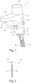
- the Fig. 1 shows a sanitary fitting 1 in a perspective view.
- the sanitary fitting 1 comprises a fitting housing 2, in which a mixing valve (not visible here) is arranged for mixing cold water and hot water to form mixed water.
- the cold water can be supplied to the mixing valve via a cold water pipe 10 and the hot water to the mixing valve via a hot water pipe 11.
- a lever 12 for setting a desired mixed water temperature and a button 13 for operating the mixing valve are arranged on the fitting housing 2. After the mixing valve is opened, the mixed water can flow from the mixing valve via an outlet 14 of the fitting housing 2 out of an outlet opening 15.
- the sanitary fitting 1 also comprises a radiation transmitter 4 and a radiation receiver 5.
- the radiation transmitter 4 and the radiation receiver 5 are arranged in the fitting housing 2 and covered by a housing part 6.
- the housing part 6 closes an opening 9 in an outer surface 3 of the fitting housing 2.
- the radiation transmitter 4 and the radiation receiver 5 are arranged in the opening 9.
- the housing part 6 is flush and gap-free with the outer surface 3 of the fitting housing 2.
- the housing part 6 has a translucent Coating 7.
- the optical appearance of the translucent coating 7 corresponds to the optical appearance of the adjacent outer surface 3 of the fitting housing 2, so that the housing part 6 is not visible on the outer surface 3 of the fitting housing 2.
- the housing part 6 is therefore shown in dashed lines.
- the translucent coating 7 is designed to be chrome-like or mirrored, so that the radiation transmitter 4 and radiation receiver 5 behind it are not visible from the outside through the housing part 6.
- the Fig. 2 shows a schematic representation of the housing part 6 of the Fig. 1 A cross-section of the sanitary fitting 1 shown.
- the housing part 6 is flat and designed like a lid.
- the translucent coating 7 is applied to a substrate 8 of the housing part 6 with a layer thickness of 17.
Landscapes
- Life Sciences & Earth Sciences (AREA)
- Engineering & Computer Science (AREA)
- Wood Science & Technology (AREA)
- Health & Medical Sciences (AREA)
- Hydrology & Water Resources (AREA)
- Public Health (AREA)
- Water Supply & Treatment (AREA)
- Domestic Plumbing Installations (AREA)
Description
- Die vorliegende Erfindung betrifft eine Sanitärarmatur zur bedarfsgerechten Bereitstellung einer Flüssigkeit. Solche Sanitärarmaturen werden insbesondere in Zusammenhang mit Spülbecken, Waschbecken, Duschen und/oder Badewannen verwendet.
- Es sind Sanitärarmaturen mit Sensoren, wie zum Beispiel Infrarotsensoren oder Radarsensoren, bekannt, beispielsweise aus
WO 2009/024219 A1 ,US 2015/0308084 A1 undUS 2017/0328048 A1 , die der Steuerung der Sanitärarmaturen dienen. Beispielsweise kann durch solche Sensoren ein Wasserfluss automatisch aktiviert werden, wenn ein Benutzer seine Hände unter die Sanitärarmatur hält. Hierzu müssen die Sensoren sichtbar an den Sanitärarmaturen angeordnet werden, da den Sensoren optische bzw. elektromagnetische Detektionsverfahren zugrunde liegen. Sanitärarmaturen weisen an ihrer Oberfläche häufig eine Chromschicht auf, die optische bzw. elektromagnetische Strahlen der Sensoren dämpfen bzw. abschirmen. Weiterhin sind Sanitärarmaturen mit Funkschnittstellen bekannt, bei denen die Chromschicht zu einer geringen Reichweite der Funkstrahlen führt. Daher können Bereiche an einer Außenfläche der Armaturengehäuse, in denen die Sensoren angeordnet sind, häufig nicht mit Chrom beschichtet werden. Dies führt zu einem optisch ungünstigen und/oder uneinheitlichen Erscheinungsbild der Sanitärarmaturen. - Aufgabe der Erfindung ist es daher, die mit Bezug auf den Stand der Technik geschilderten Probleme zumindest teilweise zu lösen und insbesondere eine Sanitärarmatur anzugeben, die ein hochwertiges optisches Erscheinungsbild aufweist.
- Diese Aufgabe wird gelöst mit einer Vorrichtung gemäß den Merkmalen des unabhängigen Patentanspruchs. Weitere vorteilhafte Ausgestaltungen der Sanitärarmatur sind in den abhängigen Patentansprüchen angegeben. Darüber hinaus werden die in den Patentansprüchen angegebenen Merkmale in der Beschreibung näher präzisiert und erläutert, wobei weitere bevorzugte Ausgestaltungen der Erfindung dargestellt werden.
- Hierzu trägt eine Sanitärarmatur mit zumindest den folgenden Komponenten bei:
- ein Armaturengehäuse mit einer Außenfläche;
- ein Strahlungssender oder Strahlungsempfänger, der zumindest teilweise in dem Armaturengehäuse angeordnet ist; und
- ein Gehäuseteil, das den Strahlungssender oder Strahlungsempfänger an der Außenfläche des Armaturengehäuses zumindest teilweise abdeckt und eine zumindest teilweise lichtdurchlässige Beschichtung aufweist; wobei
- die lichtdurchlässige Beschichtung eine Schichtdicke von 0,1 bis 0,2 µm aufweist und verspiegelt ausgeführt ist.
- Sanitärarmaturen dienen insbesondere der bedarfsgerechten Bereitstellung von Flüssigkeiten, wie insbesondere Wasser, an Spülbecken, Waschbecken, Duschen und/oder Badewannen. Hierzu kann den Sanitärarmaturen ein Kaltwasser mit einer Kaltwassertemperatur und ein Warmwasser mit einer Warmwassertemperatur zuführbar sein, die durch die Sanitärarmaturen, beispielsweise mittels eines Mischventils oder einer Thermostatmischkartusche, zu einem Mischwasser mit einer gewünschten Mischwassertemperatur mischbar sind. Die Kaltwassertemperatur beträgt insbesondere maximal 25 °C (Celsius), bevorzugt 1 °C bis 25 °C, besonders bevorzugt 5 °C bis 20 °C und/oder die Warmwassertemperatur insbesondere maximal 90 °C, bevorzugt 25 °C bis 90 °C, besonders bevorzugt 55 °C bis 65 °C. Das Mischwasser ist anschließend, beispielsweise über eine Flüssigkeitsleitung und/oder einen Auslauf, einer Auslauföffnung der Sanitärarmatur zuführbar, durch die das Mischwasser aus der Sanitärarmatur austritt.
- Die Sanitärarmatur weist ein Armaturengehäuse mit einer Außenfläche auf. Bei dem Armaturengehäuse handelt es sich insbesondere um denjenigen Teil der Sanitärarmatur, mit dem die Sanitärarmatur an einem Träger, beispielsweise einer Arbeitsplatte, befestigbar ist. Das Armaturengehäuse kann zumindest teilweise aus Kunststoff und/oder Metall, beispielsweise Messing, bestehen. Insbesondere kann das Armaturengehäuse zumindest teilweise aus Kunststoff und/oder Metall gegossen sein. Die Außenfläche des Armaturengehäuses kann eine Chrombeschichtung aufweisen, um der Sanitärarmatur eine ansprechende optische Erscheinung zu geben. Eine Schichtdicke der Chrombeschichtung beträgt mindestens 0,2 µm (Mikrometer), bevorzugt 0,2 µm bis 0,4 µm. Eine solche Schichtdicke ist für eine hohe Widerstandsfähigkeit und Haltbarkeit der Chrombeschichtung erforderlich.
- Weiterhin umfasst die Sanitärarmatur einen Strahlungssender oder Strahlungsempfänger. Insbesondere kann die Sanitärarmatur einen Strahlungssender und Strahlungsempfänger aufweisen. Der Strahlungssender dient dem Senden einer Strahlung und der Strahlungsempfänger dem Empfangen einer Strahlung. Bei der Strahlung kann es sich insbesondere um eine elektrische, magnetische und/oder elektromagnetische Strahlung, beispielsweise Infrarotstrahlen, Funkstrahlen und/oder Licht, handeln. Mittels des Strahlungssenders und/oder des Strahlungsempfängers kann beispielsweise eine Funktion der Sanitärarmatur steuerbar und/oder überwachbar sein. Hierzu können der Strahlungssender und/oder der Strahlungsempfänger mit einer Steuerung der Sanitärarmatur verbunden sein. Die Steuerung kann beispielsweise einen Mikroprozessor und/oder eine Energiequelle umfassen. Der Strahlungssender/oder Strahlungsempfänger sind zumindest teilweise in dem Armaturengehäuse angeordnet. Hierzu kann die Außenfläche des Armaturengehäuses beispielsweise eine Öffnung aufweisen.
- Weiterhin umfasst die Sanitärarmatur ein Gehäuseteil, mit dem der Strahlungssender und/oder der Strahlungsempfänger an der Außenfläche des Armaturengehäuses zumindest teilweise abgedeckt sind. Das Gehäuseteil kann einstückig bzw. stoffschlüssig mit dem übrigen Armaturengehäuse ausgebildet sein. In diesem Fall handelt es sich bei dem Gehäuseteil insbesondere um einen (abgrenzbaren) Bereich des Armaturengehäuses bzw. der Außenfläche des Armaturengehäuses. Weiterhin kann das Gehäuseteil auch eine separate Komponente darstellen, sodass das Armaturengehäuse zumindest zweiteilig ausgebildet ist. Insbesondere ist die Öffnung in der Außenfläche des Armaturengehäuses für den Strahlungssender und/oder Strahlungsempfänger durch das Gehäuseteil verschließbar bzw. abdeckbar. Das Gehäuseteil schließt bevorzugt bündig mit der angrenzenden Außenfläche des Armaturengehäuses ab. Dies kann bedeuten, dass zwischen dem Gehäuseteil und dem Armaturengehäuse an der Außenfläche kein Spalt ausgebildet ist. Weiterhin kann das Gehäuseteil plattenförmig und/oder deckelförmig ausgebildet sein.
- Das Gehäuseteil weist eine zumindest teilweise oder sogar (nahezu) vollständig lichtdurchlässige Beschichtung auf, insbesondere derart, dass eine Dämpfung der durch den Strahlungssender gesendeten Strahlung und/oder der durch den Strahlungsempfänger empfangenen Strahlung beim Durchdringen des Gehäuseteils gegenüber herkömmlichen Gehäusematerialien (signifikant) reduziert bzw. gar (praktisch) vermieden ist. Hierdurch kann eine Reichweite der durch den Strahlungssender gesendeten Strahlung erhöht und/oder ein Empfang des Strahlungsempfängers verbessert werden. Bei der lichtdurchlässigen Beschichtung kann es sich insbesondere um eine chromähnliche Beschichtung handeln. Die lichtdurchlässige Beschichtung kann einen Klarlack und eine PVD Metallisierung umfassen.
- Weiterhin weist die lichtdurchlässige Beschichtung eine besonders niedrige Schichtdicke, insbesondere von unter 2,0 µm (Mikrometer), auf. Durch das Gehäuseteil mit der lichtdurchlässigen Beschichtung ist einerseits ein hochwertiges optisches Erscheinungsbild der Sanitärarmatur und gleichzeitig eine geringe Dämpfung der gesendeten und/oder empfangenen Strahlung durch das Armaturengehäuse gewährleistet.
- Eine optische Erscheinung der lichtdurchlässigen Beschichtung kann einer optischen Erscheinung der Außenfläche des Armaturengehäuses (im Wesentlichen) entsprechen. Dies kann mit anderen Worten bedeuten, dass die lichtdurchlässige Beschichtung des Gehäuseteils optisch identisch zur angrenzenden Außenfläche des Armaturengehäuses aussehen kann. Unter die optische Erscheinung fallen insbesondere eine Farbe, ein Glanz und/oder eine Oberflächenbeschaffenheit.
- Die lichtdurchlässige Beschichtung weist eine Schichtdicke von 0,1 bis 0,2 µm auf.
- Die lichtdurchlässige Beschichtung kann durch ein PVD-Verfahren hergestellt sein. Bei dem PVD-Verfahren handelt es sich insbesondere um ein Beschichtungsverfahren mittels physikalischer Gasphasenabscheidung ("physical vapour deposition").
- Gemäß Ausführungsformen wird die PVD-Beschichtung nicht direkt auf eine Oberfläche des Gehäuseteil appliziert, sondern auf einen Basislack (Base-Coat), der als Haftvermittler / Einebner dienen kann. Gemäß weiteren Ausführungsformen kann alternativ oder zusätzlich zum Basislack unter der PVD-Beschichtung auf der PVD- Beschichtung mindestens eine weitere Lackierung ("Top-Coat") aufgebracht werden, um Abriebbeständigkeit und Korrosionsschutz zu erhöhen. Wenn hierin Bezug genommen wird auf die lichtdurchlässige Beschichtung, so kann damit gemäß Ausführungsformen ein Mehrschichtsystem (Gehäuseteil-Oberfläche/Substrat) Lack / PVD-Schicht / Lack, ein Mehrschichtsystem (Gehäuseteil-Oberfläche/Substrat) Lack / PVD-Schicht, ein Mehrschichtsystem (Gehäuseteil-Oberfläche/Substrat) PVD-Schicht / Lack, die PVD-Schicht alleine oder eine der anderen hierin beschriebenen Konfigurationen der lichtdurchlässigen Beschichtung gemeint sein. Das Bereitstellen von einer oder mehreren Lackschichten ist ein optionales Merkmal, das der Verbesserung der Eigenschaften der lichtdurchlässigen Schicht dient.
- Die mittels PVD-Verfahren hergestellte Schicht (die sich beispielsweise zwischen den Lackschichten befinden kann), kann eine keramische Hartstoffschicht aufweisen, z.B. aufweisend eine Verbindung eines Metalls (z.B. Zirkonium oder Titan) mit den Bestandteilen der im PVD-Prozess vorhandenen Reagenzgase (z.B. ZrCN / TiO2 / ZrN...). Eine so gebildete PVD-Beschichtung ist hinsichtlich der metallischen Anmutung durch die Reaktivgase einstellbar. Auf diese Weise können neben einer chromähnlichen Optik auch weitere Metallfarben (Gold-/Kupferfarben) erzeugt werden.
- Die lichtdurchlässige Beschichtung kann auf ein zumindest teilweise oder vollständig lichtdurchlässiges Substrat aufgetragen sein. Bei dem Substrat handelt es sich insbesondere um eine Außenfläche des Gehäuseteils. Das Substrat kann beispielsweise zumindest teilweise aus (transparentem) Kunststoff und/oder Glas bestehen.
- Das Gehäuseteil kann zumindest teilweise in eine Öffnung der Außenfläche des Armaturengehäuses eingesetzt sein. Hierdurch wird die Öffnung der Außenfläche des Armaturengehäuses durch das Gehäuseteil insbesondere verschlossen.
- Das Gehäuseteil kann einstückig mit dem Armaturengehäuse ausgebildet sein. Dies kann bedeuten, dass das Gehäuseteil und das Armaturengehäuse aus dem gleichen Material bestehen und/oder stoffschlüssig miteinander verbunden sind.
- Bei dem Strahlungssender oder Strahlungsempfänger kann es sich um einen Sensor handeln. Insbesondere kann es sich bei dem Strahlungssender und/oder dem Strahlungsempfänger um einen Sensor handeln. Mittels des Sensors ist beispielsweise ein Benutzer in einem Waschbereich der Sanitärarmatur erkennbar, sodass ein Flüssigkeitsfluss aus der Sanitärarmatur automatisch aktivierbar und/oder deaktivierbar ist.
- Bei dem Strahlungssender oder Strahlungsempfänger kann es sich um ein Lichtmodul handeln. Insbesondere kann es sich bei dem Strahlungssender und/oder dem Strahlungsempfänger um ein Lichtmodul handeln. Bei dem Lichtmodul kann es sich insbesondere um ein Infrarotmodul handeln.
- Bei dem Strahlungssender oder Strahlungsempfänger kann es sich um ein Funkmodul handeln. Insbesondere kann es sich bei dem Strahlungssender und/oder Strahlungsempfänger um ein Funkmodul handeln. Das Funkmodul kann beispielsweise nach Art eines WLAN- oder Bluetooth-Moduls ausgebildet sein und der Übertragung und/oder dem Empfang von Daten dienen. Bei den Daten kann es sich insbesondere um Betriebsdaten und/oder Steuerungsdaten der Sanitärarmatur handeln.
- Die Erfindung sowie das technische Umfeld werden nachfolgend anhand der Figuren näher erläutert. Es ist darauf hinzuweisen, dass die Figuren eine besonders bevorzugte Ausführungsvariante der Erfindung zeigen, diese jedoch nicht darauf beschränkt ist. Dabei sind gleiche Bauteile in den Figuren mit denselben Bezugszeichen versehen. Es zeigen beispielhaft und schematisch:
- Fig. 1:
- eine Sanitärarmatur in einer perspektivischen Darstellung; und
- Fig. 2:
- ein Gehäuseteil der Sanitärarmatur in einer Schnittdarstellung.
- Die
Fig. 1 zeigt eine Sanitärarmatur 1 in einer perspektivischen Darstellung. Die Sanitärarmatur 1 umfasst ein Armaturengehäuse 2, in dem ein hier nicht sichtbares Mischventil zum Mischen eines Kaltwassers und Warmwassers zu einem Mischwasser angeordnet ist. Das Kaltwasser ist dem Mischventil über eine Kaltwasserleitung 10 und das Warmwasser dem Mischventil über eine Warmwasserleitung 11 zuführbar. An dem Armaturengehäuse 2 ist ein Hebel 12 zur Einstellung einer gewünschten Mischwassertemperatur und ein Knopf 13 zum Betätigen des Mischventils angeordnet. Nach dem Öffnen des Mischventils kann das Mischwasser von dem Mischventil über einen Auslauf 14 des Armaturengehäuses 2 aus einer Auslauföffnung 15 abfließen. Die Sanitärarmatur 1 umfasst zudem einen Strahlungssender 4 und einen Strahlungsempfänger 5. Der Strahlungssender 4 und der Strahlungsempfänger 5 sind in dem Armaturengehäuse 2 angeordnet und durch ein Gehäuseteil 6 abgedeckt. Das Gehäuseteil 6 verschließt eine Öffnung 9 in einer Außenfläche 3 des Armaturengehäuses 2. Der Strahlungssender 4 und der Strahlungsempfänger 5 sind in der Öffnung 9 angeordnet. Weiterhin schließt das Gehäuseteil 6 bündig und spaltfrei mit der Außenfläche 3 des Armaturengehäuses 2 ab. Zudem weist das Gehäuseteil 6 eine lichtdurchlässige Beschichtung 7 auf. Die optische Erscheinung der lichtdurchlässigen Beschichtung 7 entspricht der optischen Erscheinung der angrenzenden Außenfläche 3 des Armaturengehäuses 2, sodass das Gehäuseteil 6 an der Außenfläche 3 des Armaturengehäuses 2 nicht erkennbar ist. Das Gehäuseteil 6 ist daher gestrichelt dargestellt. Weiterhin ist die lichtdurchlässige Beschichtung 7 chromähnlich bzw. verspiegelt ausgeführt, sodass der dahinterliegende Strahlungssender 4 und Strahlungsempfänger 5 von außen durch das Gehäuseteil 6 nicht sichtbar sind. Mittels des Strahlungssenders 4 ist eine Strahlung 16 durch das Gehäuseteil 6 und die lichtdurchlässige Beschichtung 7 sendbar. Entsprechend ist durch den Strahlungsempfänger 5 eine Strahlung durch das Gehäuseteil 6 und die lichtdurchlässige Beschichtung 7 empfangbar. Die Dämpfung der gesendeten und/oder empfangenen Strahlung 16 ist durch die lichtdurchlässige Beschichtung 7 im Vergleich zu den übrigen Bereichen des Armaturengehäuses 2 reduziert. - Die
Fig. 2 zeigt eine schematische Darstellung des Gehäuseteils 6 der in derFig. 1 gezeigten Sanitärarmatur 1 in einem Querschnitt. Das Gehäuseteil 6 ist hier flach und nach Art eines Deckels ausgebildet. Die lichtdurchlässige Beschichtung 7 ist mit einer Schichtdicke 17 auf ein Substrat 8 des Gehäuseteils 6 aufgebracht. -
- 1
- Sanitärarmatur
- 2
- Armaturengehäuse
- 3
- Außenfläche
- 4
- Strahlungssender
- 5
- Strahlungsempfänger
- 6
- Gehäuseteil
- 7
- lichtdurchlässige Beschichtung
- 8
- Substrat
- 9
- Öffnung
- 10
- Kaltwasserleitung
- 11
- Warmwasserleitung
- 12
- Hebel
- 13
- Knopf
- 14
- Auslauf
- 15
- Auslauföffnung
- 16
- Strahlung
- 17
- Schichtdicke
Claims (12)
- Sanitärarmatur (1), zumindest aufweisend:- ein Armaturengehäuse (2) mit einer Außenfläche (3);- ein Strahlungssender (4) oder Strahlungsempfänger (5), der zumindest teilweise in dem Armaturengehäuse (2) angeordnet ist; und- ein Gehäuseteil (6), das den Strahlungssender (4) oder Strahlungsempfänger (5) an der Außenfläche (3) des Armaturengehäuses (2) zumindest teilweise abdeckt und eine zumindest teilweise lichtdurchlässige Beschichtung (7) aufweist, dadurch gekennzeichnet, dass die lichtdurchlässige Beschichtung (7) eine Schichtdicke von 0,1 bis 0,2 µm aufweist und verspiegelt ausgeführt ist.
- Sanitärarmatur (1) nach Patentanspruch 1, wobei eine optische Erscheinung der lichtdurchlässigen Beschichtung (7) einer optischen Erscheinung der Außenfläche (3) des Armaturengehäuses (2) entspricht.
- Sanitärarmatur (1) nach einem der vorhergehenden Patentansprüche, wobei die lichtdurchlässige Beschichtung (7) durch ein PVD-Verfahren hergestellt ist.
- Sanitärarmatur (1) nach einem der vorhergehenden Patentansprüche, wobei die lichtdurchlässige Beschichtung (7) einen Lack aufweist, der sich direkt auf einer Oberfläche des Gehäuseteils (6) befindet.
- Sanitärarmatur (1) nach einem der vorhergehenden Patentansprüche, wobei auf die lichtdurchlässige Beschichtung einen transparenten Lack aufweist, der eine äußerste Schicht der lichtdurchlässigen Beschichtung (7) bildet.
- Sanitärarmatur (1) nach einem der vorhergehenden Patentansprüche, wobei die lichtdurchlässige Beschichtung (7) auf ein zumindest teilweise lichtdurchlässiges Substrat (8) aufgetragen ist.
- Sanitärarmatur (1) nach einem der vorhergehenden Patentansprüche, wobei das Gehäuseteil (6) zumindest teilweise in eine Öffnung (9) der Außenfläche (3) des Armaturengehäuses (2) eingesetzt ist.
- Sanitärarmatur (1) nach einem der Patentansprüche 1 bis 4, wobei das Gehäuseteil (6) einstückig mit dem Armaturengehäuse (2) ausgebildet ist.
- Sanitärarmatur (1) nach einem der vorhergehenden Patentansprüche, wobei es sich bei dem Strahlungssender (4) oder Strahlungsempfänger (5) um einen Sensor handelt.
- Sanitärarmatur (1) nach einem der Patentansprüche 1 bis 8, wobei es sich bei dem Strahlungssender (4) oder Strahlungsempfänger (5) um ein Lichtmodul handelt.
- Sanitärarmatur (1) nach einem der Patentansprüche 1 bis 8, wobei sich bei dem Strahlungssender (4) oder Strahlungsempfänger (5) um ein Funkmodul handelt.
- Sanitärarmatur (1) nach einem der vorhergehenden Patentansprüche, insofern auf die Ansprüche 3, 4 und 5 bezogen, wobei die lichtdurchlässige Schicht (7) ausgehend von einer Oberfläche des Gehäuseteils (6) die Schichtfolge Lack, PVD-Schicht, Lack aufweist.
Applications Claiming Priority (2)
| Application Number | Priority Date | Filing Date | Title |
|---|---|---|---|
| DE102019104234.8A DE102019104234A1 (de) | 2019-02-20 | 2019-02-20 | Sanitärarmatur mit einer lichtdurchlässigen Beschichtung |
| PCT/EP2020/052702 WO2020169333A1 (de) | 2019-02-20 | 2020-02-04 | Sanitärarmatur mit einer lichtdurchlässigen beschichtung |
Publications (2)
| Publication Number | Publication Date |
|---|---|
| EP3927906A1 EP3927906A1 (de) | 2021-12-29 |
| EP3927906B1 true EP3927906B1 (de) | 2025-06-25 |
Family
ID=69500728
Family Applications (1)
| Application Number | Title | Priority Date | Filing Date |
|---|---|---|---|
| EP20703971.0A Active EP3927906B1 (de) | 2019-02-20 | 2020-02-04 | Sanitärarmatur mit einer lichtdurchlässigen beschichtung |
Country Status (4)
| Country | Link |
|---|---|
| US (1) | US11919038B2 (de) |
| EP (1) | EP3927906B1 (de) |
| DE (1) | DE102019104234A1 (de) |
| WO (1) | WO2020169333A1 (de) |
Families Citing this family (1)
| Publication number | Priority date | Publication date | Assignee | Title |
|---|---|---|---|---|
| EP4245931B1 (de) * | 2022-03-14 | 2025-12-31 | Geberit International AG | Betätigungsvorrichtung |
Family Cites Families (8)
| Publication number | Priority date | Publication date | Assignee | Title |
|---|---|---|---|---|
| US7008073B2 (en) * | 2003-12-22 | 2006-03-07 | Stuhlmacher Ii Glen | Plumbing and lighting fixture |
| DE102007040495A1 (de) * | 2007-08-21 | 2009-02-26 | Hansgrohe Ag | Sanitärarmatur |
| US8479765B1 (en) * | 2010-07-01 | 2013-07-09 | Timothy Wren | Water faucet assembly |
| DE202011101079U1 (de) * | 2011-05-25 | 2011-06-29 | Shenter Enterprise Co., Ltd., Chang-Hua | Glasgegenstand mit verzierender Metallbeschichtung |
| US9057184B2 (en) * | 2011-10-19 | 2015-06-16 | Delta Faucet Company | Insulator base for electronic faucet |
| US9333698B2 (en) * | 2013-03-15 | 2016-05-10 | Delta Faucet Company | Faucet base ring |
| EP2937760A1 (de) * | 2014-04-23 | 2015-10-28 | Kohler Mira Limited | Systeme und verfahren zur programmierung und steuerung von wasserabgabevorrichtungen |
| JP6784933B2 (ja) * | 2016-05-13 | 2020-11-18 | Toto株式会社 | 吐水装置及び光電センサ |
-
2019
- 2019-02-20 DE DE102019104234.8A patent/DE102019104234A1/de active Pending
-
2020
- 2020-02-04 EP EP20703971.0A patent/EP3927906B1/de active Active
- 2020-02-04 WO PCT/EP2020/052702 patent/WO2020169333A1/de not_active Ceased
- 2020-02-04 US US17/413,701 patent/US11919038B2/en active Active
Also Published As
| Publication number | Publication date |
|---|---|
| US20220288634A1 (en) | 2022-09-15 |
| DE102019104234A1 (de) | 2020-08-20 |
| EP3927906A1 (de) | 2021-12-29 |
| WO2020169333A1 (de) | 2020-08-27 |
| US11919038B2 (en) | 2024-03-05 |
Similar Documents
| Publication | Publication Date | Title |
|---|---|---|
| EP3350877B1 (de) | Radom | |
| EP2559672B1 (de) | Hausgeräte-Abdeckplatte mit Fabry-Perot Interferenzschicht | |
| EP2179097B1 (de) | Sanitärarmatur mit Auslauf und Gehäuse aus Glas | |
| EP1981680B1 (de) | Bedienelement | |
| EP2668695B1 (de) | Radartransparente beschichtung | |
| EP1587968B1 (de) | Beschichtungsverfahren | |
| EP3445892B1 (de) | Verfahren zur beschichtung eines gegenstands mittels eines mehrschichtsystems mit einer nickel-phosphor-legierung | |
| EP3927906B1 (de) | Sanitärarmatur mit einer lichtdurchlässigen beschichtung | |
| WO2006136256A1 (de) | Sanitärarmatur mit einer elektrischen betätigungseinrichtung, die wenigstens einen kapazitiven sensor aufweist | |
| WO2010127866A2 (de) | Sanitärgegenstände | |
| EP2994243B1 (de) | Glanzgradeinstellung von kunststoffsubstraten mit metallischem finish | |
| DE102010019913A1 (de) | Verbundkörper mit dekorativer Hochglanzoberfläche | |
| EP3879004A1 (de) | Verfahren zur herstellung eines beschichteten bauteils für eine wasserarmatur | |
| EP2912204B1 (de) | Mit einer eingebetteten pvd-schicht beschichtetes kunststoffteil | |
| DE102007013598B3 (de) | Spiegelscheibe mit einem Substrat aus Kunststoff, ein Verfahren zu deren Herstellung sowie einen Außenspiegel mit einer solchen Spiegelscheibe | |
| DE10128332B4 (de) | Flexibles Kunststoffextrusionsprofil, insbesondere Kunststoffschlauch sowie Verfahren zu dessen Herstellung | |
| EP1480811B1 (de) | Verfahren zum aussenseitigen beschichten eines sanitären auslaufteiles sowie sanitäres auslaufteil | |
| EP0658234B1 (de) | Aus kunststoff bestehender dachentlüfter | |
| WO2022156962A1 (de) | Sanitärarmatur mit einer beschichteten komponente sowie verfahren zur beschichtung einer komponente für eine sanitärarmatur | |
| DE10319103A1 (de) | Erzeugnis mit nicht irisierender, transparenter und schützender Oberflächenschicht und entsprechendes Verfahren zur Endbearbeitung | |
| CH716843A2 (de) | Verfahren zum Beschichten von Metalloberflächen für den Küchenbereich. | |
| WO2016110538A1 (de) | Bauteil mit sol-gel-schicht und verfahren zur herstellung des bauteils | |
| DE29707351U1 (de) | Kalt-/Warmwasser-Mischbatterie für Waschtische | |
| EP2835446A1 (de) | Metallisierungsverfahren mit Schutzschicht | |
| DE20013268U1 (de) | Beschichtungssystem mit Reflexionsschicht und Glaskeramik-Überzug für Sanitär- und Haustechnikprodukte |
Legal Events
| Date | Code | Title | Description |
|---|---|---|---|
| STAA | Information on the status of an ep patent application or granted ep patent |
Free format text: STATUS: UNKNOWN |
|
| STAA | Information on the status of an ep patent application or granted ep patent |
Free format text: STATUS: THE INTERNATIONAL PUBLICATION HAS BEEN MADE |
|
| PUAI | Public reference made under article 153(3) epc to a published international application that has entered the european phase |
Free format text: ORIGINAL CODE: 0009012 |
|
| STAA | Information on the status of an ep patent application or granted ep patent |
Free format text: STATUS: REQUEST FOR EXAMINATION WAS MADE |
|
| 17P | Request for examination filed |
Effective date: 20210323 |
|
| AK | Designated contracting states |
Kind code of ref document: A1 Designated state(s): AL AT BE BG CH CY CZ DE DK EE ES FI FR GB GR HR HU IE IS IT LI LT LU LV MC MK MT NL NO PL PT RO RS SE SI SK SM TR |
|
| DAV | Request for validation of the european patent (deleted) | ||
| DAX | Request for extension of the european patent (deleted) | ||
| STAA | Information on the status of an ep patent application or granted ep patent |
Free format text: STATUS: EXAMINATION IS IN PROGRESS |
|
| 17Q | First examination report despatched |
Effective date: 20231214 |
|
| GRAP | Despatch of communication of intention to grant a patent |
Free format text: ORIGINAL CODE: EPIDOSNIGR1 |
|
| STAA | Information on the status of an ep patent application or granted ep patent |
Free format text: STATUS: GRANT OF PATENT IS INTENDED |
|
| INTG | Intention to grant announced |
Effective date: 20250331 |
|
| GRAS | Grant fee paid |
Free format text: ORIGINAL CODE: EPIDOSNIGR3 |
|
| GRAA | (expected) grant |
Free format text: ORIGINAL CODE: 0009210 |
|
| STAA | Information on the status of an ep patent application or granted ep patent |
Free format text: STATUS: THE PATENT HAS BEEN GRANTED |
|
| AK | Designated contracting states |
Kind code of ref document: B1 Designated state(s): AL AT BE BG CH CY CZ DE DK EE ES FI FR GB GR HR HU IE IS IT LI LT LU LV MC MK MT NL NO PL PT RO RS SE SI SK SM TR |
|
| REG | Reference to a national code |
Ref country code: GB Ref legal event code: FG4D Free format text: NOT ENGLISH |
|
| REG | Reference to a national code |
Ref country code: CH Ref legal event code: EP |
|
| REG | Reference to a national code |
Ref country code: DE Ref legal event code: R096 Ref document number: 502020011282 Country of ref document: DE |
|
| REG | Reference to a national code |
Ref country code: CH Ref legal event code: EP |
|
| REG | Reference to a national code |
Ref country code: IE Ref legal event code: FG4D Free format text: LANGUAGE OF EP DOCUMENT: GERMAN |
|
| P01 | Opt-out of the competence of the unified patent court (upc) registered |
Free format text: CASE NUMBER: APP_32287/2025 Effective date: 20250703 |
|
| PG25 | Lapsed in a contracting state [announced via postgrant information from national office to epo] |
Ref country code: FI Free format text: LAPSE BECAUSE OF FAILURE TO SUBMIT A TRANSLATION OF THE DESCRIPTION OR TO PAY THE FEE WITHIN THE PRESCRIBED TIME-LIMIT Effective date: 20250625 |
|
| REG | Reference to a national code |
Ref country code: LT Ref legal event code: MG9D |
|
| PG25 | Lapsed in a contracting state [announced via postgrant information from national office to epo] |
Ref country code: GR Free format text: LAPSE BECAUSE OF FAILURE TO SUBMIT A TRANSLATION OF THE DESCRIPTION OR TO PAY THE FEE WITHIN THE PRESCRIBED TIME-LIMIT Effective date: 20250926 Ref country code: NO Free format text: LAPSE BECAUSE OF FAILURE TO SUBMIT A TRANSLATION OF THE DESCRIPTION OR TO PAY THE FEE WITHIN THE PRESCRIBED TIME-LIMIT Effective date: 20250925 |
|
| PG25 | Lapsed in a contracting state [announced via postgrant information from national office to epo] |
Ref country code: BG Free format text: LAPSE BECAUSE OF FAILURE TO SUBMIT A TRANSLATION OF THE DESCRIPTION OR TO PAY THE FEE WITHIN THE PRESCRIBED TIME-LIMIT Effective date: 20250625 |
|
| PG25 | Lapsed in a contracting state [announced via postgrant information from national office to epo] |
Ref country code: HR Free format text: LAPSE BECAUSE OF FAILURE TO SUBMIT A TRANSLATION OF THE DESCRIPTION OR TO PAY THE FEE WITHIN THE PRESCRIBED TIME-LIMIT Effective date: 20250625 |
|
| PG25 | Lapsed in a contracting state [announced via postgrant information from national office to epo] |
Ref country code: RS Free format text: LAPSE BECAUSE OF FAILURE TO SUBMIT A TRANSLATION OF THE DESCRIPTION OR TO PAY THE FEE WITHIN THE PRESCRIBED TIME-LIMIT Effective date: 20250925 |
|
| PG25 | Lapsed in a contracting state [announced via postgrant information from national office to epo] |
Ref country code: LV Free format text: LAPSE BECAUSE OF FAILURE TO SUBMIT A TRANSLATION OF THE DESCRIPTION OR TO PAY THE FEE WITHIN THE PRESCRIBED TIME-LIMIT Effective date: 20250625 |
|
| REG | Reference to a national code |
Ref country code: NL Ref legal event code: MP Effective date: 20250625 |
|
| PG25 | Lapsed in a contracting state [announced via postgrant information from national office to epo] |
Ref country code: NL Free format text: LAPSE BECAUSE OF FAILURE TO SUBMIT A TRANSLATION OF THE DESCRIPTION OR TO PAY THE FEE WITHIN THE PRESCRIBED TIME-LIMIT Effective date: 20250625 |
|
| PG25 | Lapsed in a contracting state [announced via postgrant information from national office to epo] |
Ref country code: PT Free format text: LAPSE BECAUSE OF FAILURE TO SUBMIT A TRANSLATION OF THE DESCRIPTION OR TO PAY THE FEE WITHIN THE PRESCRIBED TIME-LIMIT Effective date: 20251027 |
|
| PG25 | Lapsed in a contracting state [announced via postgrant information from national office to epo] |
Ref country code: IS Free format text: LAPSE BECAUSE OF FAILURE TO SUBMIT A TRANSLATION OF THE DESCRIPTION OR TO PAY THE FEE WITHIN THE PRESCRIBED TIME-LIMIT Effective date: 20251025 |
|
| PG25 | Lapsed in a contracting state [announced via postgrant information from national office to epo] |
Ref country code: SM Free format text: LAPSE BECAUSE OF FAILURE TO SUBMIT A TRANSLATION OF THE DESCRIPTION OR TO PAY THE FEE WITHIN THE PRESCRIBED TIME-LIMIT Effective date: 20250625 |
|
| PG25 | Lapsed in a contracting state [announced via postgrant information from national office to epo] |
Ref country code: CZ Free format text: LAPSE BECAUSE OF FAILURE TO SUBMIT A TRANSLATION OF THE DESCRIPTION OR TO PAY THE FEE WITHIN THE PRESCRIBED TIME-LIMIT Effective date: 20250625 |
|
| PG25 | Lapsed in a contracting state [announced via postgrant information from national office to epo] |
Ref country code: PL Free format text: LAPSE BECAUSE OF FAILURE TO SUBMIT A TRANSLATION OF THE DESCRIPTION OR TO PAY THE FEE WITHIN THE PRESCRIBED TIME-LIMIT Effective date: 20250625 |
|
| PG25 | Lapsed in a contracting state [announced via postgrant information from national office to epo] |
Ref country code: EE Free format text: LAPSE BECAUSE OF FAILURE TO SUBMIT A TRANSLATION OF THE DESCRIPTION OR TO PAY THE FEE WITHIN THE PRESCRIBED TIME-LIMIT Effective date: 20250625 |
|
| PG25 | Lapsed in a contracting state [announced via postgrant information from national office to epo] |
Ref country code: SK Free format text: LAPSE BECAUSE OF FAILURE TO SUBMIT A TRANSLATION OF THE DESCRIPTION OR TO PAY THE FEE WITHIN THE PRESCRIBED TIME-LIMIT Effective date: 20250625 |
|
| PG25 | Lapsed in a contracting state [announced via postgrant information from national office to epo] |
Ref country code: ES Free format text: LAPSE BECAUSE OF FAILURE TO SUBMIT A TRANSLATION OF THE DESCRIPTION OR TO PAY THE FEE WITHIN THE PRESCRIBED TIME-LIMIT Effective date: 20250625 |
|
| PG25 | Lapsed in a contracting state [announced via postgrant information from national office to epo] |
Ref country code: DK Free format text: LAPSE BECAUSE OF FAILURE TO SUBMIT A TRANSLATION OF THE DESCRIPTION OR TO PAY THE FEE WITHIN THE PRESCRIBED TIME-LIMIT Effective date: 20250625 |
|
| PG25 | Lapsed in a contracting state [announced via postgrant information from national office to epo] |
Ref country code: IT Free format text: LAPSE BECAUSE OF FAILURE TO SUBMIT A TRANSLATION OF THE DESCRIPTION OR TO PAY THE FEE WITHIN THE PRESCRIBED TIME-LIMIT Effective date: 20250625 |